


Table of Contents
\\SERVER\Current EMV10 documentation
Important Safeguards
Introduction and Features
Specification
Components - Port Locations
Installation - Valve Dimensions
Installation – Slowdown Distance / Control Signals
Installation – Field Wiring Diagram
Valve Controller Board Features
Valve Setup
Display Menu
Display Menu Continued
Troubleshooting Check List – Up Section
Troubleshooting Check List – Down Section
Troubleshooting Check List – Miscellaneous
Error History
Terms and Conditions
1
2
3
4
5
6
7
8
9
10
11
12
13
IMPORTANT SAFEGUARDS
Read Instructions: All Safety, installation, and setup instructions should be read before installing or operating the EMV10 Electronic Motor Valve.
Failure to follow the installation and setup instruction may result in unsatisfactory performance, equipment damage, or physical injury.
1. Service: There are no user serviceable parts contained herein. Refer all service to qualified service personnel only.
2. Risk of Electrical Shock: Do not remove the valve cover except when making adjustments or servicing the valve. Always turn off all electrical
power sources before servicing any mechanical part or assembly. Do not place metal objects in contact with the energized Electronic Control
Board at any time.
3. EMV10 Power Sources: The EMV10 Electronic Motor Valve uses multiple electrical power sources. Hazardous voltages may be present
even if one source to the EMV10 is secured. Verify all voltage sources to the EMV10 are secured before making repairs.
4. Wiring: All wiring should be routed in such a way that it is not likely to be pulled, pinched, stepped on, have objects placed on it, or damaged
in any way.
5. Retain User Manual: The user manual should be retained for future reference.
INTRODUCTION AND FEATURES
The Maxton EMV10 Electronic Motor Valve was designed to meet a growing demand for low use limited access (LULA), handicapped and residential
hydraulic elevator applications. The EMV10 combines hydraulic and electronic control to provide excellent ride quality. The EMV10 has all the features
found in a commercial hydraulic control valves plus electronic safety control and adjustments allowing quick set up and easy problem analysis.
FEATURES
• Quick set up and less field adjustments required.
• Built in pressure and viscosity compensation.
• Ride performance is maintained from empty to fully loaded condition.
• Acceleration and deceleration are independent of load and oil viscosity.
• Regulated contract down speed, up leveling speed and down leveling speed.
• Stabilized leveling speed is achieved in a very short distance.
1728 ORBIT WAY - MINDEN - NEVADA - 89423-4114 - PHONE: 775-782-1700 - FAX: 775-782-1701 - WEB: maxtonvalve.com - EMAIL: info@maxtonvalve.com
1
SPECIFICATIONS
\\SERVER\Current EMV10 documentation
EMV10
SPECIFICATIONS
Flow Range 3 - 12 gpm 11 - 45 lpm
Operating Pressure
Min 150 psi 10 bar
Max 1000 psi 69 bar
Line Ports 3/4” NPT
Gauge Ports “B” 1/8” NPT
Pressure Port “S” 1/8” NPT
Operating Temperature 80 - 150ºF 26 - 65ºC
Oil Type
Electrical Input Provided by Elevator Contractor
Valve Controller Power Supply
Pump Disable Circuit
Coil Input Signals +110 VAC
Overall Dimensions:
Width: 5-7/8” 149.2 mm
Height: 7 9/16” 192.1 mm
Depth: 8” 203.2 mm
Weight: 14 lbs. 6.4 kg.
STANDARD METRIC
Hydraulic ISO VG 32 150 SUS @ 100ºF
or equivalent biodegradable oil
+24 VDC 3.2A (Regulated)
+110 VAC
Pressure switch port
“S” (on valve body)
Programming port
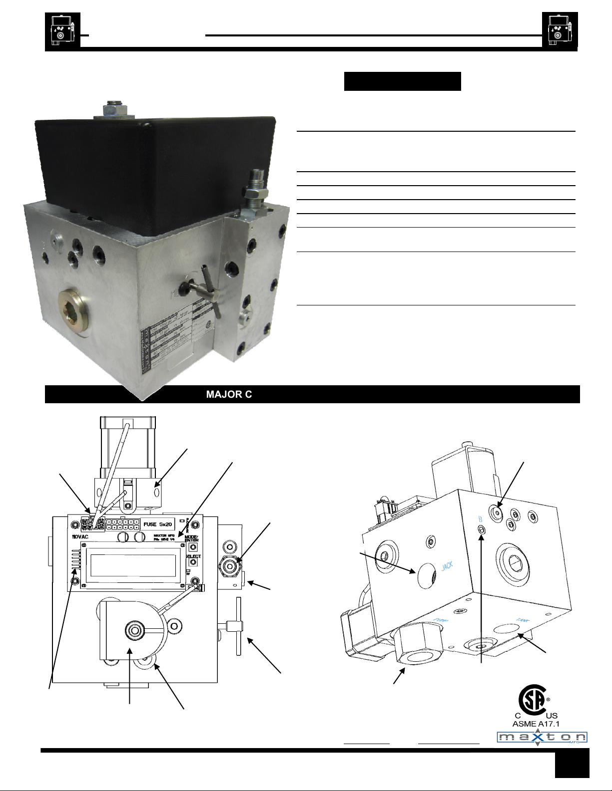
MAJOR COMPONENTS & PORT LOCATIONS
Motor Flow Control
(MFC) Assembly
Valve Control Board
(VCB)
Relief Adjuster
JACK Port
Compensator
Strainer Access
Manual Lowering
(Twist)
PUMP Port
JACK Pressure
Gauge Port “B”
Check Closing Orifice
TANK Port
Down (DV)
Solenoid & Coil
1728 ORBIT WAY - MINDEN - NEVADA - 89423-4114 - PHONE: 775-782-1700 - FAX: 775-782-1701 - WEB: maxtonvalve.com - EMAIL: info@maxtonvalve.com
Check Open
Orifice
2
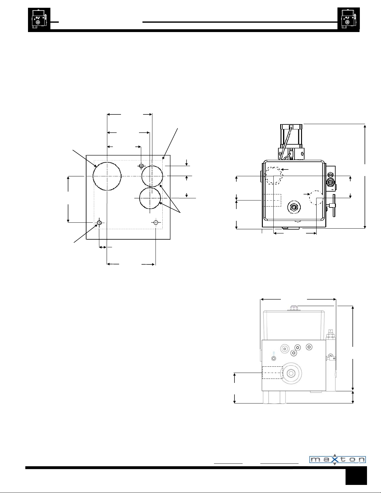
VALVE DIMENSIONS
\\SERVER\Current EMV10 documentation
2” (51 mm) dia.
Cut out of tank lid
3-5/16"
(84.1 mm)
PORT LOCATIONS:
Use pipe or hose fittings with the following port
locations as shown:
Pump: ¾” NPT Jack: ¾” NPT Tank: ¾” NPT
3-7/32"
(81.8 mm)
3-1/16"
(77.8 mm)
2-7/16"
(61.9 mm)
Valve
.730”
(18.5 mm)
1-9/16"
(39.7 mm)
1-1/2” (38 mm) dia.
Cut out of tank lid
PUMP PORT
(below)
1-13/16"
(46 mm)
JACK
PORT
2-5/16"
(58.7 mm)
TANK PORT
(below)
1-9/16"
(39.7 mm)
8"
(203.8 mm)
Mounting holes (3) places typical
1/4-20 threads
9/32 (7.1 mm) dia.
Cut out of tank lid
MOUNTING HOLES GUIDELINE: TOP VIEW
The dimensions above are for the cutout and hole
pattern if the valve is mounted on the tank lid.
9/16"
(14.3 mm)
3-7/16"
(87.3 mm)
2-3/8"
(60.3 mm)
JACK
PORT
1"
(25.4 mm)
3"
(77.8 mm)
5-7/8"
(149.2 mm)
6-9/16"
(166.7 mm)
1"
(25.4 mm)
1728 ORBIT WAY - MINDEN - NEVADA - 89423-4114 - PHONE: 775-782-1700 - FAX: 775-782-1701 - WEB: maxtonvalve.com - EMAIL: info@maxtonvalve.com
3
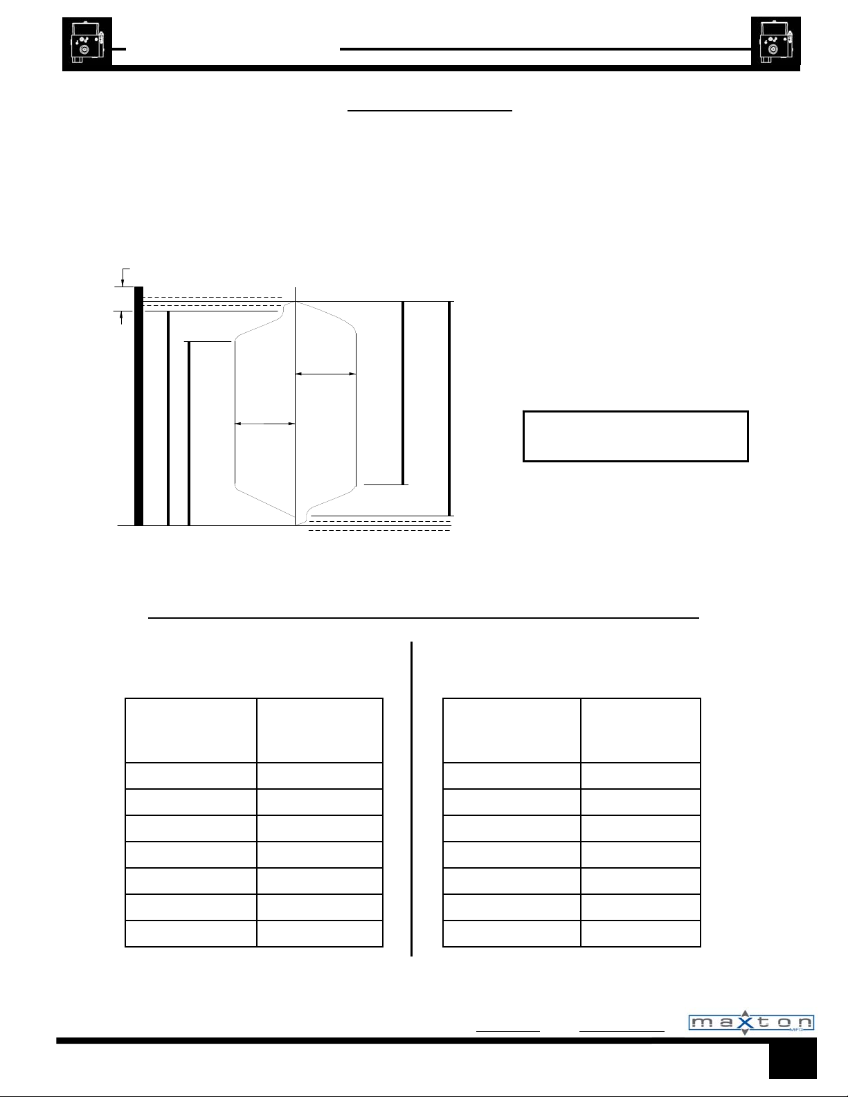
SLOWDOWN DISTANCE
\\SERVER\Current EMV10 documentation
Installer to provide U, UL, D, and DL signals from main elevator controller to VCB (Valve Control Board).
CONTROL SIGNAL SEQUENCE
• UL: For up travel, turn on at pump start, turn off to stop. With UL signal on and pump running, car moves up at leveling speed. For “soft stop”
pump should run about one half second after UL signal is turned off.
• U: Turn on with UL to run up at contract speed. Turn off at slowdown distance from floor.
• DL: Turn on to move downward at leveling speed. Turn off to stop.
• D: Turn on with DL signal to run down at contract speed. Turn off at slowdown distance above floor.
1/2 to 1 second after US signal cut off
PUMP
DOWN
FULL SPEED
UL
U
UP
FULL SPEED
D
DL
Control signals are 110VAC and
provided by elevator contractor
RECOMMENDED SLOWDOWN DISTANCE FOR HOISTWAY SWITCH INSTALLATION
2-1/2” for each 10 FPM of car speed or use slowdown
distance table below:
Elevator Speed
(ft./min.)
Slow down
distance
(in.)
30 8
35 9
40 10
45 11
50 12 ½
55 13 ¾
60 15
127 cm for each 1 m/s of car speed or use slowdown distance
table below:
Elevator Speed
(m/sec.)
Slow down
distance
(cm)
0.15 20.3
0.18 22.9
0.20 25.4
0.23 27.9
0.25 31.8
0.28 35.6
0.30 38.1
1728 ORBIT WAY - MINDEN - NEVADA - 89423-4114 - PHONE: 775-782-1700 - FAX: 775-782-1701 - WEB: maxtonvalve.com - EMAIL: info@maxtonvalve.com
4

FIELD WIRING DIAGRAM (110VAC BOARD)
\\SERVER\Current EMV10 documentation
MAXTON FIELD INTERFACE CABLE
Included with Valve
Warning:
Failure to correctly follow the recommended procedures may
result in damage and/or a hazardous condition.
\
Verify all voltages before applying power. Incorrect voltages will
damage the EMV10 control board. Power supply must be regu-
lated at +24VDC and Rated at 3.2 amps minimum.
Interface to the EMV10 uses Maxton Field Interface Cable.
Color coded wires are used to identify each electrical connection.
Connect each wire to the elevator controller function as described
below.
PUMP RUN INPUT FROM CONTROLLER (110VAC input)
(Red wire). Warning: Failure to use this circuit can result
in a hazardous condition. This wire should be connected in
such a fashion that if a valve malfunction occurs, pump
Operation is prohibited. The PUMP RUN INPUT FROM
CONTROLLER wire is connected internally on the valve
control board to the input side of a SSR (Solid State Relay).
This wire should be connected to the elevator controller’s
110VAC pump run signal.
7. OUTPUT TO PUMP/MOTOR STARTER (output)
(Brown wire). Warning: Failure to use this circuit can
result in a hazardous condition. This wire must be
connected in such a fashion that if a valve malfunction occurs,
pump operation is prohibited.
The OUTPUT TO PUMP/MOTOR STARTER wire is
connected internally on the valve control board to the output
side of a SSR. This wire should be connected to the 110VAC
pump/motor starter.
6. Coil Common (Yellow). Connect to the coil common signal
(110VAC(N)).
2. DL Coil Signal (Yellow / Blue). Connect the 110VAC down
leveling coil signal here.
3. D Coil Signal (Yellow / Red). Connect the 110VAC down high
speed coil signal here.
4. UL Coil Signal (Yellow / Black). Connect the 110VAC up
leveling coil signal here.
5. U Coil Signal (Yellow / Brown). Connect the 110VAC up high
speed coil signal here.
8. DC Return (Violet). Connect to the 24VDC power supply
(negative) - return.
9. +24VDC @ 3.2A (Blue). Connect to a regulated +24VDC
power supply, rated at a 3.2 amps minimum. This is the
primary valve power source. The 24VDC power supply should
be switched on / off by the elevators main power source.
12. Ground (Green). Connect to Earth ground.
1728 ORBIT WAY - MINDEN - NEVADA - 89423-4114 - PHONE: 775-782-1700 - FAX: 775-782-1701 - WEB: maxtonvalve.com - EMAIL: info@maxtonvalve.com
5

VALVE CONTROLLER BOARD FEATURES
\\SERVER\Current EMV10 documentation
LCD Display
Programming
Port
VALVE SET UP
Motor & Sensor
Connector
Interface
Connector
“POWER”
LED INDICATOR
“MODE/ENTER”
BUTTON
“SELECT”
BUTTON
“DV” COIL
LED INDICATOR
Solenoid Coil
Connector
FACTORY SETTING: All valves are factory tested and set to the job specifications provided. Factory settings should only be changed if accurate car
speed information is available to the technician.
NORMAL OPERATION MODE: Make sure all connectors are plugged in to the VCB (Valve Control Board). The green “POWER” indicator is on and
there is no errors listed on the LCD display. These conditions indicate normal valve operation.
PRESSURE RELIEF ADJUSTMENT:
THE INFORMATION PRESENTED HEREIN IS FOR USE BY SKILLED HYDRAULIC ELEVATOR PROFESSIONALS
• Land car in pit and install pressure gauge in port “B”.
• Register an up call with a fully loaded car, making note of pressure gauge reading.
• Cancel the up call.
• Close the manual shut off valve to the jack.
• Set the relief adjuster to the minimum pressure position. To do this turn the relief adjuster screw fully CW until seated. Then turn CCW 3 full turns.
• Register an up call, observe pressure gauge and turn the relief adjuster CW to increase the pressure gage reading. The final setting should be in
accordance with state and local code requirements.
• Cancel the up call.
• Snugly tighten the relief adjuster nut.
• Register an up call to verify the pressure relief setting.
• Cancel the up call.
• Open the manual shut off valve to the jack.
VALVE SET UP:
• Register up and down calls to verify FLOW (high speed), leveling speed, acceleration, deceleration and stop rates.
• If necessary, use the MODE/ENTER button to navigate to the ride quality setting to select different ride quality (rate). Setting “0” (factory default)
provides the softest ride quality (rate), setting “9” provides the hardest ride quality (rate).
MANUAL LOWERING (ML):
• ML is Twist style located on the right side of the valve.
• Turn ML OUT (CCW) to lower car when necessary. Manual lowering speed may vary with system pressure and jack size.
PROCEDURE FOR SETTING OVERSPEED FLOW WITH 11 AND 12 GPM WORKING FLOW:
• After completely setting up the valve including the down flow. With car at the bottom floor, turn the Relief (R) adjuster out (CCW) to stop.
• Make an up call. Car should not move. Turn the Relief adjuster slowly IN (CW) until the car moves then one more turn IN. Car should make
normal up run and stop at the upper floor.
• Turn the Relief adjuster OUT (CCW) one turn. Make a down call. Car should be running down at speed faster than normal down run. Check car
speed if it complies with the Codes, 110 to 140 % of normal down high speed. If not, turn the Relief adjuster OUT (CCW) for faster or IN (CW) for
slower down high speed. Note the number of turns in this step.
• If an up run is needed, turn the Relief adjuster IN (CW) the same number of turn in Step 3.
• When the down high speed for overspeed condition is obtained, set the overspeed valve (or governor) as required.
1728 ORBIT WAY - MINDEN - NEVADA - 89423-4114 - PHONE: 775-782-1700 - FAX: 775-782-1701 - WEB: maxtonvalve.com - EMAIL: info@maxtonvalve.com
6

DISPLAY MENU
\\SERVER\Current EMV10 documentation
MAIN MENU
DISPLAY
Notification
• Press “MODE/ENTER” button to cycle through the menu
• Flashing cursor indicates current setting
DESCRIPTION FUNCTION
Main Screen
(Run Mode)
Ride Quality (Rate)
Adjustment
Up Leveling
Adjustment
Down Leveling
Adjustment
Advanced Menu
(OverSpeed, Error, Defaults)
Upon power up, the Main Screen will Display. Screen must be active for
valve to operate in run mode. Screen displays active coil inputs during
operation and software version. Inputs are U, UL, D and DL.
Press “SELECT” button to cycle through ten levels of Ride Quality Settings.
Press “SELECT” button to cycle through +/- 3 fpm of adjustment in up
leveling.
Press “SELECT” button to cycle through +/- 3 fpm of adjustment in down
leveling.
Press “SELECT” button to cycle to “Y” (yes) and press the “MODE/ENTER”
button to enter the “ADVANCED MENU”. This menu allows you to enter
Overspeed Mode, view Error History, Delete Error History and Restore
Defaults
ADVANCED MENU
DISPLAY
Setup Menu
(Jack, Flow, Sizi ng )
Factory Menu
(Set Defaults, Software Reset)
PASSWORD REQUIRED
FUNCTION
Overspeed Mode
110% - 140% of
down flow value
View Error History
Delete Error History
Press “SELECT” button to cycle to “Y” (yes) and press the “MODE/ENTER”
button to enter the “SETUP MENU”. This menu allows you to change the
Jack Type, Jack Size, MFC Sizing, and Leveling Sizing.
Press “SELECT” button to cycle to “Y” (yes) and press the “MODE/ENTER”
button to enter the “FACTORY MENU”. This Menus allows you to Set the
Defaults and Reset to Program Defaults.
DESCRIPTION
Press “SELECT” button to cycle to “Y” (yes) and press the “MODE/ENTER”
button to enter the “OVERSPEED MODE” This function allows the user to
perform an overspeed test enabling the valve to
operate between 110% to 140% above the normal down flow setting in
down direction. Return to the Main Menu (Run Mode) to perform test. You
must cycle power or return to Overspeed Mode to turn off and return to
normal operation
** Not applicable with a working flow setting of 11 or 12 GPM **
Press “SELECT” button to cycle to “Y” (yes) and press the “MODE/ENTER”
button to view the error history. Valve will store up to 10 errors and will cycle
through them automatically. Possible errors: MFC Motor or MFC Sensor
Error.
Press “SELECT” button to cycle to “Y” (yes) and press the “MODE/ENTER”
button to delete the error history. There will be a confirmation and the
screen will automatically cycle to the next menu.
1728 ORBIT WAY - MINDEN - NEVADA - 89423-4114 - PHONE: 775-782-1700 - FAX: 775-782-1701 - WEB: maxtonvalve.com - EMAIL: info@maxtonvalve.com
Restore Default
Settings
Press “SELECT” button to cycle to “Y” (yes) and press the “MODE/ENTER”
button to restore default settings. This function will return the valve settings
to when the original job specifications provided by the
customer.
7

DISPLAY MENU CONTINUED
\\SERVER\Current EMV10 documentation
SETUP MENU
DISPLAY
Jack Type
Jack Size
Up Flow Adjustment
Down Flow Adjustment
MFC Sizing
(Only if instructed by
Maxton tech support)
Up Leveling Sizing
(Only as instructed by
Maxton tech support)
Down Leveling Sizing
(Only as instructed by
Maxton tech support)
DESCRIPTION FUNCTION
Press “SELECT” button to cycle through and select from two Jack Types,
Roped or Direct
Press “SELECT” button to cycle through and select from fourteen metric
and standard jack sizes ranging from 1 1/2” - 4”.
Press “SELECT” button to cycle through and select from nineteen
contract flow settings, ranging from 3 – 12 GPM.
Press “SELECT” button to cycle through and select from nineteen
contract flow settings, ranging from 3 – 12 GPM.
Press “SELECT” button to cycle to “Y” (yes) and press the “MODE/ENTER”
button to enter the “MFC SIZING”. Register up call when prompted. Adjust
size setting by pressing the “MODE/ENTER” button to increase sizing or
“SELECT” button to decrease sizing until the car reaches 0.3fpm
Press “SELECT” button to cycle to “Y” (yes) and press the “MODE/ENTER”
button to enter the “UL SIZING”. Register up call when prompted. Adjust size
setting by pressing the “MODE/ENTER” button to increase sizing or
“SELECT” button to decrease sizing until the car reaches 8.0fpm
Press “SELECT” button to cycle to “Y” (yes) and press the “MODE/ENTER”
button to enter the “DL SIZING”. Register down call when prompted. Adjust
size setting by pressing the “MODE/ENTER” button to increase sizing or
“SELECT” button to decrease sizing until the car reaches 8.0fpm
FACTORY MENU
DISPLAY
PASSWORD REQUIRED
Set Customer Defaults
(Only as instructed by
Maxton tech support)
Reset Software
(Only as instructed by
Maxton tech support)
DESCRIPTION FUNCTION
Press “SELECT” button to cycle to “Y” (yes) and press the
“MODE/ENTER” button to save the customer defaults.
Press “SELECT” button to cycle to “Y” (yes) and press the
“MODE/ENTER” button to reset all valve settings to software default.
1728 ORBIT WAY - MINDEN - NEVADA - 89423-4114 - PHONE: 775-782-1700 - FAX: 775-782-1701 - WEB: maxtonvalve.com - EMAIL: info@maxtonvalve.com
8

TROUBLESHOOTING CHECK LIST – UP SECTION
\\SERVER\Current EMV10 documentation
The first section of the check list deals with the UP movement, while the second deals with the DOWN movement. Use the following reference materials in conjunction with the trouble shooting check list: Hydraulic Schematics, Operating Sequences, Setup Instructions, and Electronic Controller Status
Code Indications.
SYMPTOM CAUSE CHECK REF.
Up call registered but no
up travel.
Pump runs, car does not
move.
Up Compensator Valve not closing.
Up Acceleration rough.
Up high speed slow.
Up Leveling Speed slow /
Stall
Car overshoots floor.
Harsh Up Stop
No power to VCB. Check VCB POWER indication. P6
Pump not running. Check pump disable circuit wiring P5
Line shut-off valve Check line shut-off valve open.
No UL Input signal to VCB. Verify UL input signal.
No U and UL signals to VCB.
LED’s are off or dim.
Relief pressure set too low Check correct Relief pressure is set. P6
Clogged orifices, strainer. Check for oil contamination.
Up Compensator Spool jammed. Up Compensator Spring broken.
Ride Quality setting. Change Ride Quality Setting. P6 , 7
Sizing position incorrect. Call Maxton For Assistance
Rail and / or packing friction.
Low pump motor horsepower.
Relief pressure set too low.
Pump output low.
Incorrect Flow setting. Change Flow setting. P6, 7
Incorrect MFC sizing position. Call Maxton For Assistance
Incorrect Jack size setting. Change Jack size setting P6, 7
Incorrect Leveling Speed setting. Change Leveling Speed setting. P6, 7
Incorrect MFC sizing position. Call Maxton For Assistance
Incorrect Jack size setting. Change Jack size setting P6, 7
Coil Sequence wrong
Up Leveling Speed too fast. Change Up Leveling Speed setting. P6, 7
Ride Quality selection too soft. Change Ride Quality Setting. P6, 7
Up flow setting higher then actual
pump output.
Incorrect Jack size setting. Change Jack size setting. P6, 7
U and/or UL signals turn off late.
Not enough pump time
Check for U, UL signals at elevator controller.
Check for a broken or loose field interface cable
from elevator controller to VCB.
Call Maxton for Assistance
Check jack packing and guide shoes for
excessive friction.
Check motor horsepower rating.
Check line voltage.
Check Relief pressure setting.
Note: If the Relief pressure is too low, the down
high speed will be faster than normal.
Check pump specification.
Check pump inlet strainer.
Check controller for proper coil signal timing.
(i.e. U and UL dropping then UL re-energizing)
Reset Flow setting. P6, 7
Check hoist way deceleration and stop switches.
Correct slowdown distance, if necessary.
Increase pump time. The pump should continue to
run for about one second after the car stops.
P5 , 6
P2
P6
P4 , 6
P4
1728 ORBIT WAY - MINDEN - NEVADA - 89423-4114 - PHONE: 775-782-1700 - FAX: 775-782-1701 - WEB: maxtonvalve.com - EMAIL: info@maxtonvalve.com
9

TROUBLESHOOTING CHECK LIST – DOWN SECTION
\\SERVER\Current EMV10 documentation
SYMPTOM CAUSE CHECK REF.
Down call registered
but no down travel.
Car slowly creeps down
when down call registered
Down leak
Slow start
Harsh or bouncy down
start
Abrupt down start
Down high speed too slow
Down speed not
regulated (too fast)
Car overshoots floor
Down leveling slow or
stalled.
Down stop too soft or
hard.
1728 ORBIT WAY - MINDEN - NEVADA - 89423-4114 - PHONE: 775-782-1700 - FAX: 775-782-1701 - WEB: maxtonvalve.com - EMAIL: info@maxtonvalve.com
No power to VCB.
Line shut-off valve Check line shut-off valve open.
Tripped pipe rupture valve Check and reset pipe ruptur e valve.
D or DL signals to VCB missing.
Check the solenoid LED for power to the coil. Physically pick up the coil
DV solenoid not energized
MFC malfunction Replace MFC, Call Maxton For Assistance
DV solenoid
Check Orifice PN#876 Undersized Verify Orifice Dimension is .021
MFC malfunction Replace MFC, Call Maxton For Assistance
Leak at jack or line Close line shut-off valve. If car still drifts down,
Leak at DV solenoid Check solenoid seat P2
Leak at Main Check Valve
Manual Lowering Leaking
Rail and packing friction Check jack packing and guide shoe tightness.
Ride Quality setting Change Ride Quality Setting P7
Air in hydraulic system Bleed air from jack.
Rail and / or packing friction Check jack packing and guide shoes for excessive friction.
Shuttle stuck
Incorrect MFC sizing position Call Maxton For Assistance
Incorrect Flow setting Reset Flow setting. P6 , 7
Shuttle stuck
Clogged orifices or strainer Check for oil contamination. P2
D and DL signal from elevator
Down Leveling Speed too fast Change Down Leveling Speed setting. P6 , 7
Rate profile selection too soft Change Ride Quality setting. P6 , 14
Incorrect Down Leveling setting Change Down Leveling setting.
controller
Incorrect Jack size setting Change Jack size setting.
Rate profile selection Change Ride Quality setting.
Incorrect Jack size setting Change Jack size setting
Turn ML (Manual Lowering) screw out (CCW) and then turn in (CW) fully
(quickly put it back) to feel the magnetic field at the coil.
Remove check seat and view for damage and/or debris,
Make a full up run. Wait for 10 seconds, then make a down run. If
Check hoist way deceleration and stop switches. Adjust slowdown
Check VCB POWER indication
Check VCB Fuse
Verify D, DL signals at elevator controller.
Check for a broken or loose field interface wire
from elevator controller to VCB.
Replace coil, if necessary.
Check voltage to solenoid coil.
Replace solenoid coil, if necessary.
Call Maxton For Assistance
to insure a good seat.
Call Maxton For Assistance
problem repeats Call Maxton For Assistance
distance, if necessary.
P6
P5 , 6
P5 , 6
P5 , 6 Check that DV solenoid is energized.
P4
P6 , 7
P6 , 7
10

TROUBLESHOOTING CHECK LIST - MISCELLANEOUS
\\SERVER\Current EMV10 documentation
SYMPTOM CAUSE CHECK REF.
After a run is complete car
moves down 2-8" during
pressure relief routine.
Erratic up and down
movement
(Stop and Go)
Up high speed bogs down
motor,
down leak present
Down High Speed
fluctuation,
Excessive noise on down
run
Closing Orifice Clogged Remove closing orifice and check for debris. 2
Check Piston not closed Call Maxton For Assistance
Sensor unable to read encoder disk
Check piston Stuck Call Maxton For Assistance
Pump Shuttle Stuck Call Maxton For Assistance
Remove sealant and check sensor cavity for oil. Clean with contact
cleaner and dry with compressed air
1728 ORBIT WAY - MINDEN - NEVADA - 89423-4114 - PHONE: 775-782-1700 - FAX: 775-782-1701 - WEB: maxtonvalve.com - EMAIL: info@maxtonvalve.com
11

ERROR HISTORY
\\SERVER\Current EMV10 documentation
The valve controller program incorporates self diagnostic routines designed to identify conditions that can result in
incorrect or abnormal valve operation. The diagnostic routines have the ability to auto-correct most conditions that may be
encountered.
Error History:
If an error condition occurs the VCB will momentarily stop car movement, interrupt the pump operation and display an
error. If possible clear the cause of the condition and automatically return to normal operation. If experien ci ng large
numbers of error conditions, check the cables for loose connections and proper power to the VCB. To determine if an
error condition has occurred navigate to the Advanced Menu where there is a view history mode. This mode once entered
will display a number of errors recorded up to ten and then display those errors automatically at a three second interval.
Erase Error History:
To erase error history, navigate to the Delete History in the Advanced Menu. Select yes and there will be a confirmation
screen notifying that the operation is complete.
Note 2: For proper operation the elevator pump operation must be interrupted under various conditions.
Therefore be sure to utilize the PUMP DISABLE CIRCUITS in the valve installation as described on pg. 5
Error Meaning Probable Cause Action
Motor Failure MFC motor position error
Sensor
Failure
MFC motor position error
MFC MOTOR not moving
MFC sensor damaged or blocked
MFC MOTOR not moving
MFC sensor damaged or blocked
Check Motor and Sensor for damage. Replace if necessary
Check Motor and Sensor for damage. Replace if necessary
Check Motor and Sensor for damage. Replace if necessary
Check Motor and Sensor for damage. Replace if necessary
Version 1.0
1728 ORBIT WAY - MINDEN - NEVADA - 89423-4114 - PHONE: 775-782-1700 - FAX: 775-782-1701 - WEB: maxtonvalve.com - EMAIL: info@maxtonvalve.com
12

TERMS AND CONDITIONS
\\SERVER\Current EMV10 documentation
FORWARD: The products and information contained herein have been developed by MAXTON MANUFACTURING COMPANY. They are subject to
change. The information is intended for use by professionals trained in the manufacture, installation and maintenance of hydraulic elevator systems.
While the information is deemed reliable, MAXTON disclaims any liability arising from misinterpretation.
LIMITED WARRANTY: All control and safety valves sold by MAXTON are warranted only to purchasers for resale or for use in business or original
equipment manufacture against defects in workmanship or materials, under normal use, for two (2) years from date of purchase. Any part which is
determined by MAXTON to be defective in material or workmanship, and is returned to MAXTON, shipping costs prepaid, as exclusive remedy, will be
repaired or replaced at MAXTON'S option. This warranty cannot be transferred or assigned to third parties. All warranties are considered null and void
upon transfer unless the intent to transfer to a third party is expressly indicated in a purchase order or the customer is a known OEM and a user of
MAXTON'S products. Alteration or removal of designated serial numbers will cause the warranty to be immediately null and void.
WARRANTY DISCLAIMER: MAXTON has made diligent effort to provide illustrations, descriptions and technical information for the proper use of its
products. In addition MAXTON provides on-line and phone technical support for the use of our various products. Nevertheless, there are no warranties
given except such expressed warranties offered in connection with the sale of a particular product as stated in the Limited Warranty above. THERE ARE
NO EXPRESS OR IMPLIED WARRANTIES OF MERCHANTABILITY OR OF FITNESS FOR A PARTICULAR PURPOSE GIVEN IN CONNECTION
WITH THE SALE OF ANY GOODS. In no event shall MAXTON MANUFACTURING COMPANY be liable for consequential, incidental, or special
damages. The sole and exclusive remedy, and the limit of MAXTON'S liability for any loss whatsoever, shall not exceed the price paid by the purchaser
for the product to which the claim is made.
PRODUCT SUITABILITY: Many states and localities have codes and regulations governing sales, construction, installation and/or use of products,
which may vary from those in neighboring areas. While MAXTON attempts to assure that its products comply with such codes, it cannot guarantee
compliance, and cannot be responsible for how the product is installed or used. Before purchase and use of a product, review the application, and
national and local codes and regulations to be sure that the product, installation and use comply.
RETURN/REPAIR INQUIRIES: All in- and out-of-warranty repairs are to be directed to the MAXTON Sales Department. Before returning a product,
contact Sales or Technical Support to obtain a return authorization number (RA #). The designated RA # should then be marked on the outside of the
package. To avoid processing delays, be sure to include the following: Purchase order number and RA #, returnee's name, address and phone number,
the model number and serial number, repair instructions and description of problem. All pipes, coils and covers must be removed prior to shipping.
MAXTON will not be responsible for lost or damaged pipes, coils or covers. Pipes requiring removal by MAXTON are subject to removal charges. A
valve returned with missing components is subject to replacement charges. All products must be returned freight prepaid. Brokerage fees, taxes and
duties, when applicable, must be paid by returnee. New product returned for credit is subject to a 15% restocking fee, plus the original freight charge.
MODIFICATION AND/OR UNAUTHORIZED REPAIRS: In the ev ent of modification and/or repair of a MAXTON product by an unauthorized repair
facility, you will indemnify and hold MAXTON harmless from any liability or damage whatsoever arising out of the subsequent use of the product. Use of
an unauthorized repair facility voids all warranty claims.
PRODUCT PRICING: Product prices are subject to change without notice.
1728 ORBIT WAY - MINDEN - NEVADA - 89423-4114 - PHONE: 775-782-1700 - FAX: 775-782-1701 - WEB: maxtonvalve.com - EMAIL: info@maxtonvalve.com
13
 Loading...