

P-51D Mustang
Sport Scale Model Aircraft
Assembly and Instruction Manual
Warning:
This radio controlled model is not a toy. It requires skill to fly and is not recommended for
the novice pilot. It should not be operated by children without the supervision of a suitably
experienced adult. Max-Thrust reserves the right to modify the specification of this model at
any time.
© Century UK Limited 2011. All rights reserved.

Safety Precautions
1) Do not attempt to repair or modify this aircraft with non-factory parts.
2) Never fly this model over roads, railway lines, near to power lines, airports, buildings or
any people.
3) Do not fly this model in excessively strong winds, in the rain, or thunderstorms.
4) Do not fly or launch the model towards people.
5) Keep hands and face away from rotating propeller at all times.
6) We strongly recommend that all fixings and fasteners used in the construction of this
model are checked regularly for integrity. Failure to do so could cause a crash or personal
injury.
7) We only recommend the use of 2.4GHz radio equipment with this model.
Disclaimer
1) This radio controlled model is not a toy. Used incorrectly it is capable of inflicting serious
injury to persons or damage to property. The owner/pilot assumes all responsibility for
any damage to persons or property resulting from the use of this product.
2) The manufacturer and distributor decline all responsibility for any liability arising from
use of this product.
3) It is very important that you follow all instructions for assembling and setting up of this
model. Failure to do so could result in a loss of control and possibly a crash.
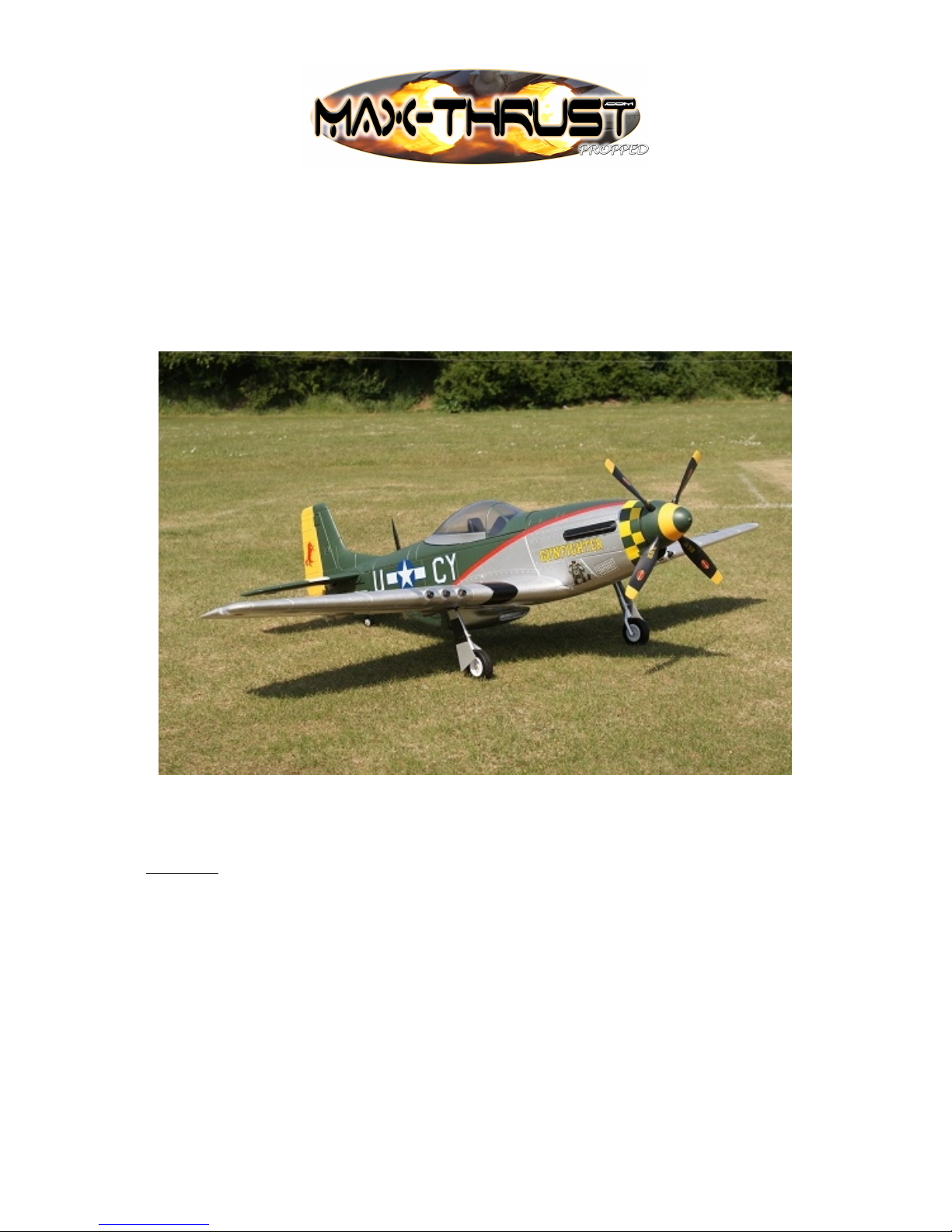
Overview
Thank-you for purchasing this MAX-THRUST P-51D Mustang radio controlled model
aircraft. The P-51D Mustang offers a stunning combination of terrific looks and sensational
flight performance. Manufactured from “EPOFLEXY” it is extremely robust, however, in
the event of a “less than perfect” arrival, we supply a range of spares to get you flying again
in the shortest time. It is capable of a wide range of aerobatic manoeuvres to thrill the
experienced pilot, but with reduced control throws it provides a solid and predictable flight
performance, perfect for the sports flyer. We are certain you will enjoy your new model,
please take the time to read this manual thoroughly and understand its contents completely
prior to commencing assembly.
Key Features
Powerful Brushless Motor
70A Brushless ESC
Retracting Undercarriage
Highly Detailed 4 Blade Propeller
Factory Applied Decals
Pre-Installed servos
“Live” Control Surface Hinging
Durable “EPOFLEXY” Construction
Steerable Tail Wheel
Specification
Wingspan: 1600mm
Length: 1400mm
Flying Weight: 2500g
Motor: 4558 Out-runner
ESC: 70A
Servos: 4 x 9g - 2 x 17g
Battery: 3350mAh - 5550mAh 4S 14.8V Li-Po (Not Included)
1
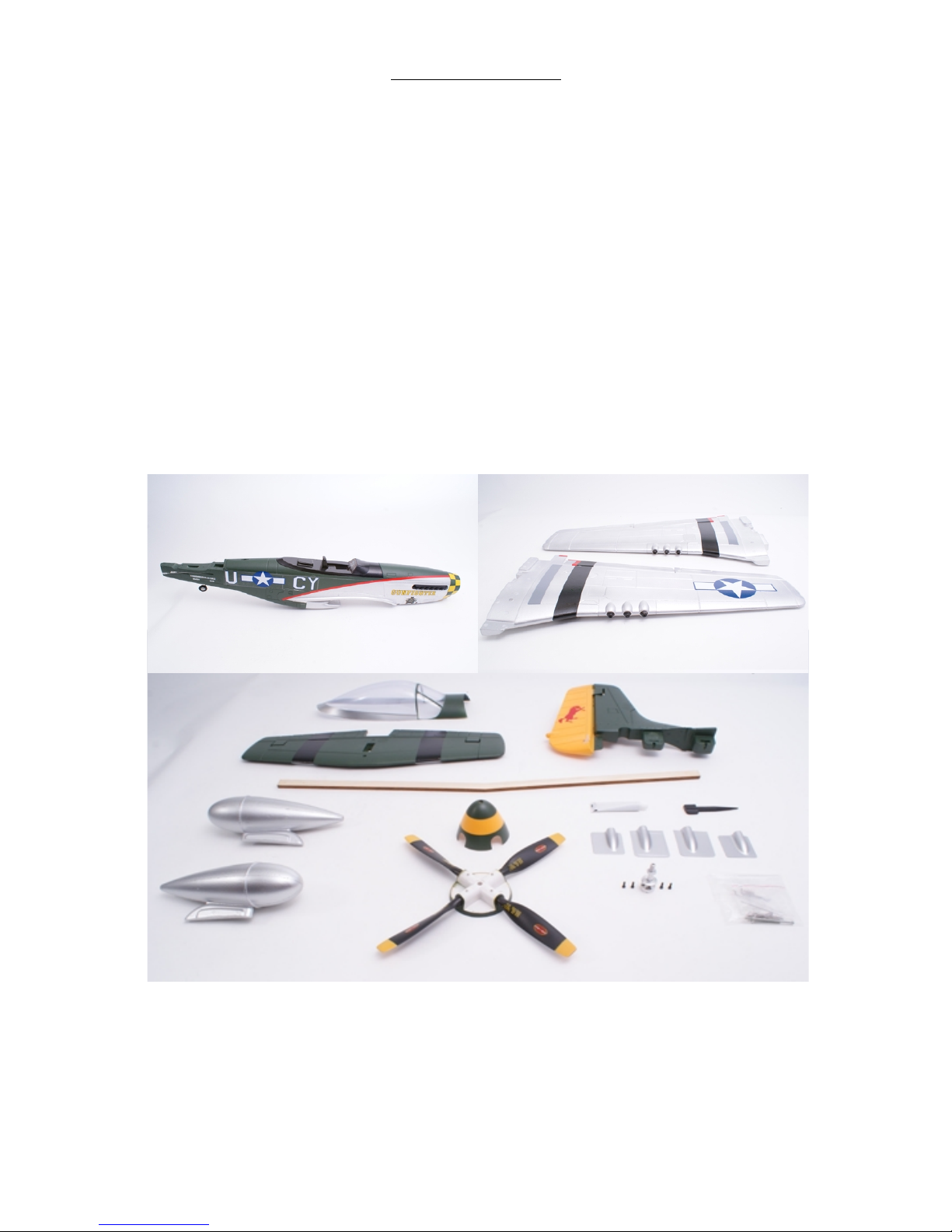
COMPONENTS LIST
1. Fuselage 8. Spinner
2. Wing Panels 9. Propeller
3. Canopy 10. Adhesive
4. Horizontal Stabilizer 11. Aerial
5. Fin & Rudder 12. Servo Covers
6. Main Spar 13. Propeller Adaptor
7. Drop Tanks 14. Fixings Pack
2
1
2
3
4
5
6
7
8
9
10
11
12
13
14
Tools Required to Complete
1. Screwdrivers 5. Scissors
2. Pliers 6. Measure or Ruler
3. 14mm Spanner 7. Drill
4. Modelling Knife 8. Fine Abrasive Paper
Additional Items Required to Complete
3350mAh - 5550mAh 4S 14.8V Li-Po battery (Power -Tech 5550mAh 33C 4S 14.8V
Recommended, Part No. PT-B-3355504S)
Charger (Power-Tech C6, B606 or X-Drive recommended)
2.4GHz Transmitter
2.4GHz Receiver
Self-Adhesive Tape
Velcro Battery Fastening
Thread Locking Compound
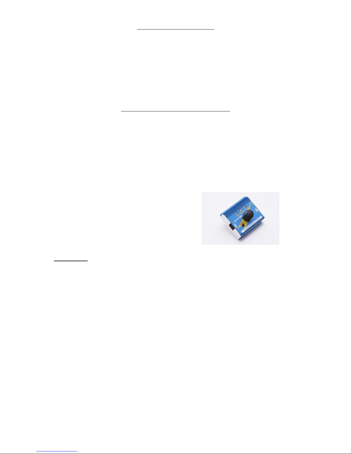
Recommended Item:
Servo Tester (Power-Tech, Part No. PT-ACC-ST)
Please Note:
“EPOFLEXY” is a very tough and durable material perfect for the manufacture of model
aircraft. When using screwed fixings with “EPOFLEXY” components it is important to
tighten the screws sufficiently to provide a firm fixing.
Excess tightening could result in the foam material becoming compressed, possibly damaging
or distorting the part. Take care to ensure that all screws are tightened sufficiently to provide
a firm fixing, but do-not over tighten. We recommend that all fixings are checked regularly
for security and safety purposes.
3

1. Hinge Check
Check that all control surface hinges are firmly
secured. If required they can be glued in position
using a small quantity of the supplied adhesive.
2. Horizontal Tail Plane
Fix the elevator control horn in the moulded recess as
shown using four M2 x 15mm screws, (image 1).
Make certain that the plastic horn is fitted to the
correct side, with the plastic reinforcement plate fixed
in the moulded recess on the top side of the elevator. 1
Temporarily fix the horizontal tail plane in position on the fuselage using the two M3 x
40mm screws, (image 2). Make certain the horizontal tail plane is positioned squarely on the
fuselage, (the fin slot should line up perfectly with the aperture below in the fuselage) then
use a pen to lightly mark the position of the fuselage on the underside of the tail plane,
(image 3).
2 3
Remove the tail plane from the fuselage. Using a light grade abrasive paper, lightly abrade
the painted mating surfaces to provide a good key for the adhesive, (image 4). Using the
adhesive, glue the horizontal tail plane in position, (image 5).
4 5
Secure in position using the two M3 x 40mm screws, (image 2). Use the adhesive sparingly
towards the edges of the parts to be glued and immediately wipe any excess from the joint.
4

3. Vertical Fin & Rudder
Fix two plastic control horns either side of the rudder in the moulded recesses. Use two M2 x
30mm screws, used in opposite directions through the rudder, (image 6). Using a light grade
abrasive paper, lightly abrade the painted mating surfaces to provide a good key for the
adhesive, (image 7).
6 7
At this stage it will be necessary to lower the tail wheel to expose one of the two fixing holes
for the tail fin. DO NOT ATTEMPT TO MANUALLY LOWER THE TAILWHEEL.
Remove the cockpit hatch from the fuselage and locate the tail wheel servo lead marked 5.
Temporarily connect the servo lead to the retract channel of your receiver. Locate the lead
marked 3 from the ESC and plug it into the throttle channel of your receiver, then plug the
lead marked 6 into any spare channel of the receiver. Connect your flight battery to the
power lead from the ESC. Use the retract switch on your transmitter lower the tail wheel.
Alternatively, we recommend the use of a Power-Tech servo tester which is an easy and
effective way to centre, operate and test servos without the need for an R/C system, (Part No.
PT-ACC-ST).
Apply adhesive sparingly to the mating surface of the
fuselage and push the fin assembly into position.
Remove any excess adhesive immediately. Secure in
place using the two M3 x 50mm screws via the
fixing holes positioned underneath the fuselage,
(image 8).
8
4. Fuselage Control Rods
Centre the elevator and rudder servos. The rudder push rods may appear to be too short at
this stage. The additional length required will be achieved by slackening the corresponding
screws on the servo horn fixings and adjusting the
rod length. Connect the elevator and rudder plastic
links to their control horns. Make certain that the
control surfaces are in their neutral positions and that
the plastic links are “snapped” closed, (image 9).
Remember to re-tighten the servo fixing screws, we
recommend the use of a small amount of thread-lock.
Any minor adjustments to the neutral positions of the
control surfaces can be made by rotating the plastic
9 link on the threaded portion of the control rod.
5

5. Wing Assembly
Starting with the left hand wing panel, fix the aileron control horn and its backing plate in
position using the four M2 x 15mm screws, (image 10). Then securely fix the flap control
horn in position using four M2 x 10mm screws that screw directly into the control surface,
without the requirement for a backing plate, (image 11).
10 11
Check the operation of the wing servos and ensure
they are correctly centred. Locate the aileron and flap
control rods and connect them to their respective
servos, (image 12). Note: The Z-bend of the control
rod is located in the second hole down on the servo
horn. Connect the plastic control links to the
corresponding horns on the control surfaces, ensuring
that the control surfaces are in their neutral positions
and that the plastic links are “snapped” closed.
12
Any minor adjustments can be made by rotating the plastic link on the threaded portion of the
control rod.
Locate the plastic wing servo covers, trim to obtain a perfect fit, (image 13 + 14) then using
the supplied adhesive glue in position, (image 15).
13 14
15
6
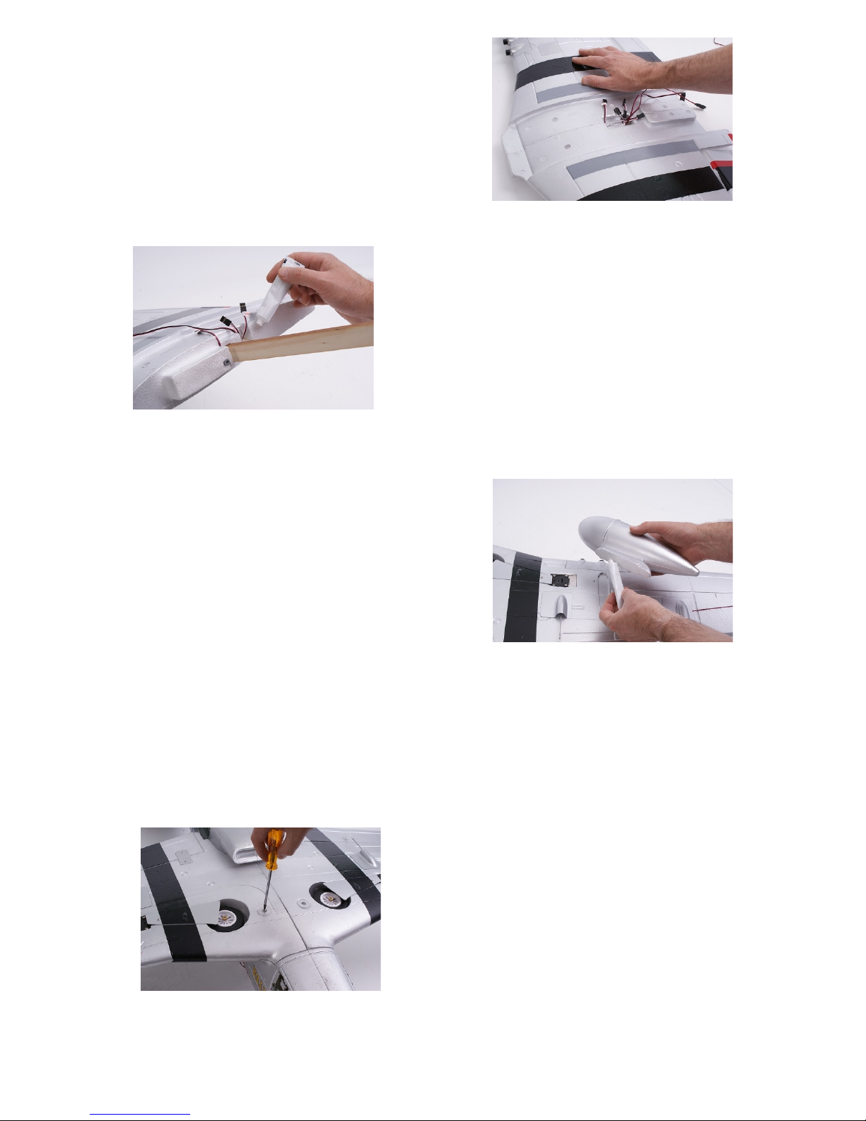
Repeat the process for the right hand wing panel.
Locate the wooden wing spar and dry-fit the two
wing halves onto the spar to ensure a good fit. Make
certain that all of the servo leads are routed correctly
there are no gaps at the root of the panels, (image
16).
Note: Due to the moulding process, a very small
amount of trimming may be required to obtain a
perfect fit. 16
Remove the panels from the spar and lightly abrade
the mating surfaces of the wing roots to ensure a
good key for the adhesive (image 17).
Apply adhesive to one half of the spar and slide into
position on the corresponding wing panel. Then
apply adhesive to the root section of that wing panel
and the remaining exposed section of the spar. Slide
the remaining wing panel onto the spar ensuring that
the servo leads are routed correctly.
For ease of transportation and storage, it is possible to
fly your P-51D Mustang without using adhesive to
join the wing panels. However, we always
recommend that they are glued together as this
provides a huge amount of additional strength to the
model. If you wish to fit the optional drop tanks,
(included) do so now using the supplied adhesive,
(image 18).
18
Connect aileron and flap control leads to the corresponding “Y” lead connectors. The plugs
are marked as follows:-
No.1 = Ailerons
No.5 = Retracting Gear
No.6 = Flaps
Position the wing onto the fuselage and fix in place
with the two M3 x 75mm screws, (image 19). Make
certain that all control wires are kept inside the
fuselage and do not foul the wing seat area.
19
7
17
6. Receiver Installation.
Note: We only recommend the use of 2.4GHz radio equipment with this model and make the
following recommendations for receiver location and mounting. These must be followed in
conjunction with the instructions supplied by your receiver manufacturer.
Connect the aileron, retracting gear and flap leads to corresponding outputs on your receiver.
Locate the leads from the ESC, the control lead with only black and red wires should be
connected to the remaining black and red lead from the wing. This is the power supply to the
navigation lights.
The lead marked 3 is the throttle control and should be connected to the corresponding output
on your receiver. Connect the retracting tail wheel lead to the spare socket on the 'Y'-lead
marked 5. The remaining lead marked 6 is for the UBEC system and should be connected to
any spare output on your receiver.
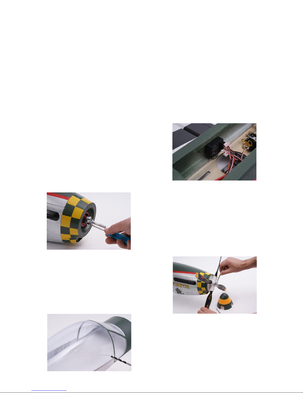
Please double check that all plugs are connected to
the correct outputs on your receiver and that all leads
are routed in a neat and tidy manner. Mount the
receiver in the position shown, (image 20) using your
choice of double sided self-adhesive or “Velcro” tape.
The ESC will be held in place with the battery
retaining strap. Remove it from this position and
secure to the side of the fuselage with self-adhesive
“Velcro” tape.
20
7. Final Assembly
Fit the aluminium propeller adaptor to the motor
using the 4 x M2.5 x10mm cap head screws, (image
21). It is very important that these fixings are
tightened securely. Remove the propeller nut and
washer from the shaft. Slide the rear section (back
plate) of the spinner onto the shaft making certain
that the square “key” of the shaft locates into the
corresponding aperture in the back plate moulding.
21
Slide the propeller onto the shaft, followed by the
washer and secure in position with the propeller nut,
(image 22). The propeller nut needs to tightened
very securely. Fit the spinner with the M3 x 45mm
screw. For optimum performance, some pilots may
wish to balance the propeller.
22
If you wish to install a pilot figure, do so now. We
recommend that you drill two small holes as shown
in the clear canopy to allow any heat to disperse,
(image 23).
8
23
Carefully apply adhesive to the foam section of the canopy assembly, (image 24). Use the
adhesive sparingly and position the clear canopy in place on the moulding, (image 25). Allow
to dry thoroughly before attempting to fit the assembly onto the fuselage.
24 25
The canopy is held in position with a rubber
retaining band located in the fuselage and preinstalled magnetic catches, (image 26). Do not
attempt to fly the model without the canopy secured
in position with the retaining band attached.
26
Fix the aerial in position using the supplied adhesive,
(image 27).
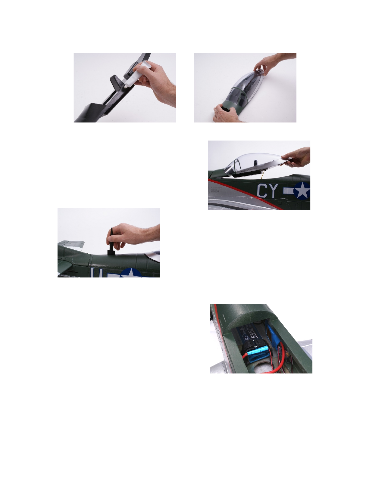
8. Battery Installation
Your flight battery, (not included) needs to be firmly
secured in the battery compartment to prevent it from
moving in flight, (image 28). The model includes one
battery positioning strap, however the battery will
require an additional method of fixing to provide
adequate security. Because most experienced pilots
will have a preferred method of battery retention, this
has not been included with the model. We
recommend the use of additional straps combined with 28
self-adhesive “Velcro” tape.
9
27

9. Final Checks
Double check that all fixings and fasteners used on the model are secure, including snap
links, servos screws, wheel retaining screws etc. Check that all control surfaces are moving in
the correct direction in relation to control inputs from your transmitter.
We recommend the following control throws for initial flights, however these can be adjusted
to suit your personal preference after flight testing has been completed.
Elevator: 10mm deflection each way.
Ailerons: 8mm deflection each way.
Rudder: 15mm deflection each way.
Flaps: 60 degrees deflection maximum.
The centre of gravity of your P-51D Mustang is
110mm back from the furthest forward point of the
wing, (image 29). Using the recommended 5550mAh
flight battery, this centre of gravity should be easily
achieved. If you choose to use a lighter battery it will
be necessary to add additional ballast to the model in
order to achieve the correct centre of gravity.
29
10
 Loading...