

Page 1
Instruction Manual
Page 2
Statement
Warning:
This radio controlled model is not a toy. It requires skill to y and is not recommended for use by
beginners without assistance from an experienced model pilot. It should not be operated by children
without the supervision of a suitably experienced adult.
Max-Thrust reserves the right to modify the specication of this model at any time.
Safety Precautions
1. Do not attempt to repair or modify this aircraft with non-factory parts.
2. Never y this model over roads, railway lines, near to power lines, airports, do not y this model in
excessively strong winds, in the rain, or thunderstorms.
3. Do not y or launch the model towards people.
4. Keep hands and face away from rotating propeller at all times.
5. We strongly recommend that all xings and fasteners used in the construction of this model are
checked regularly for integrity. Failure to do so could cause a crash, injury to yourself or others around
you.
6. We only recommend the use of 2.4GHz radio equipment with this model.
Disclaimer
1. This radio controlled model is not a toy. Used incorrectly it is capable of inicting serious injury to
persons or damage to property. The owner/pilot assumes all responsibility for any damage to persons or
property resulting from the use of this product.
2. The manufacturer and distributor decline all responsibility for any liability arising from use of this
product.
3. It is very important that you follow all instructions for assembling and setting up of this model. Failure to
do so could result in a loss of control and possibly a crash
Page 3
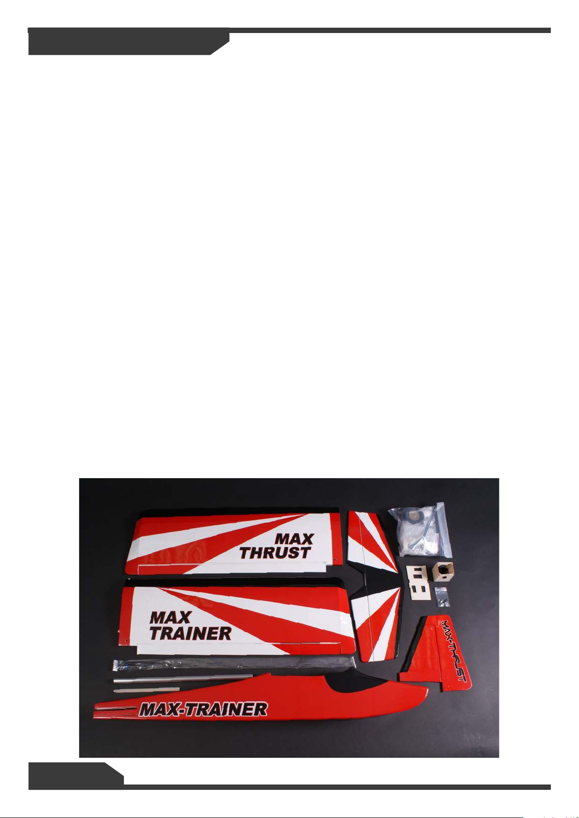
Items Required
Some pictures throughout this manual may be of the prototype model and some details may now have
changed. If you have any questions please contact us [email protected].
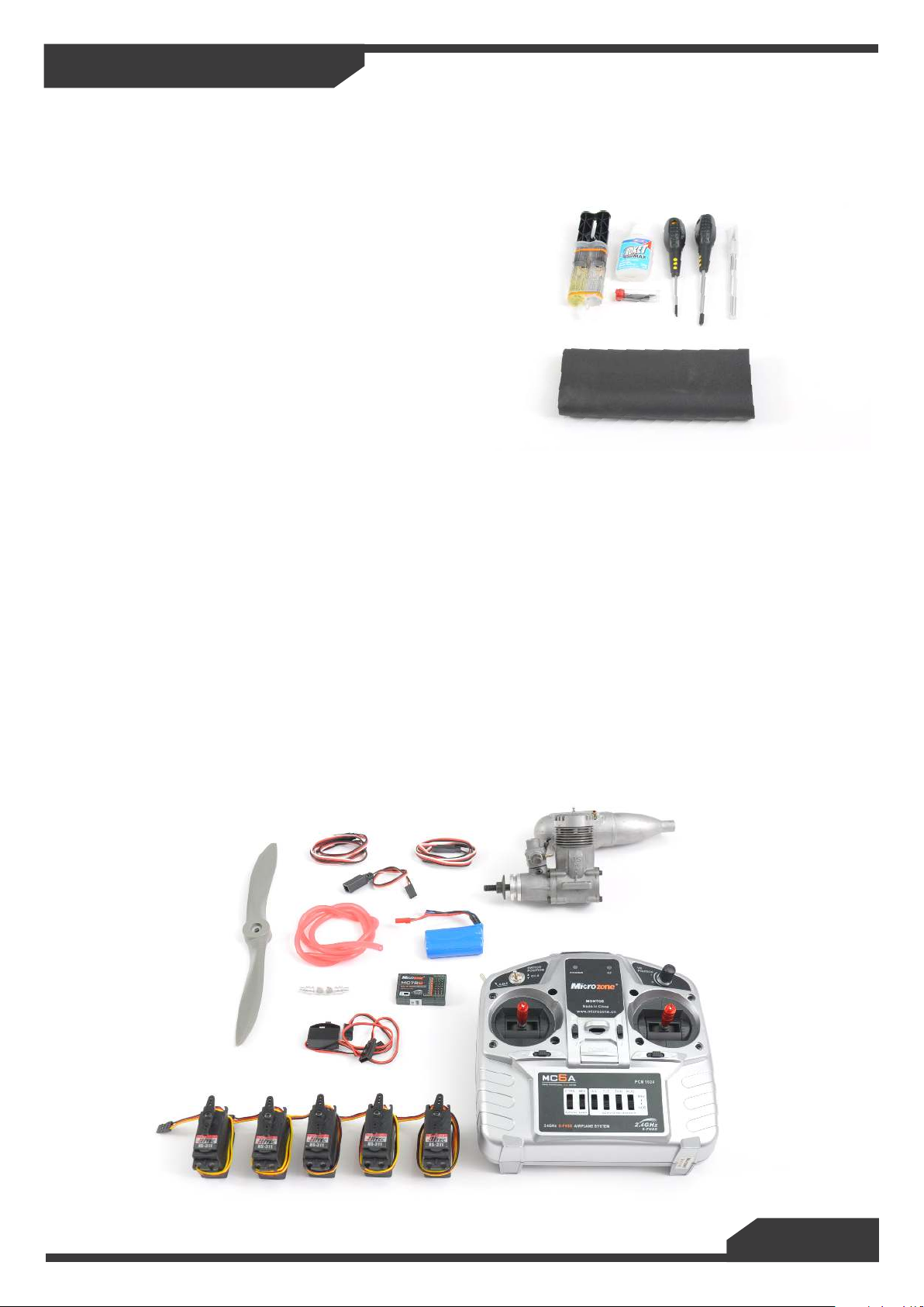
Tools:
Philips Screwdriver Medium
Philips Screwdriver Small
Modelling Knife and Spare Blades
3mm Allen Key
2mm Allen Key
5 Minute Epoxy Glue
Slow Cyanoacrylate Glue (Cyno)
Foam Padding
Equipment:
1 x Transmitter and Receiver
5 x Standard or Small Servos IC version - 4 x Standard or Small Servos Electric Version
2 x 200mm Servo Extension Leads
1 x 200mm Y-Lead
Electric Version
1 x Overlander 3536/08 Thumper or
Equivalent
1 x Electronic Speed-controller
1 x Suitable Propeller and Propeller Adapter
1 x Battery 11.1v 3s 2200mAh
IC Version:
1 x 32-40 Size Model Engine
1 x Suitable Propeller
1 x Receiver Battery
1m Fuel Tube
1 x Fuel Filter
Page 4
Building Your Max-Trainer
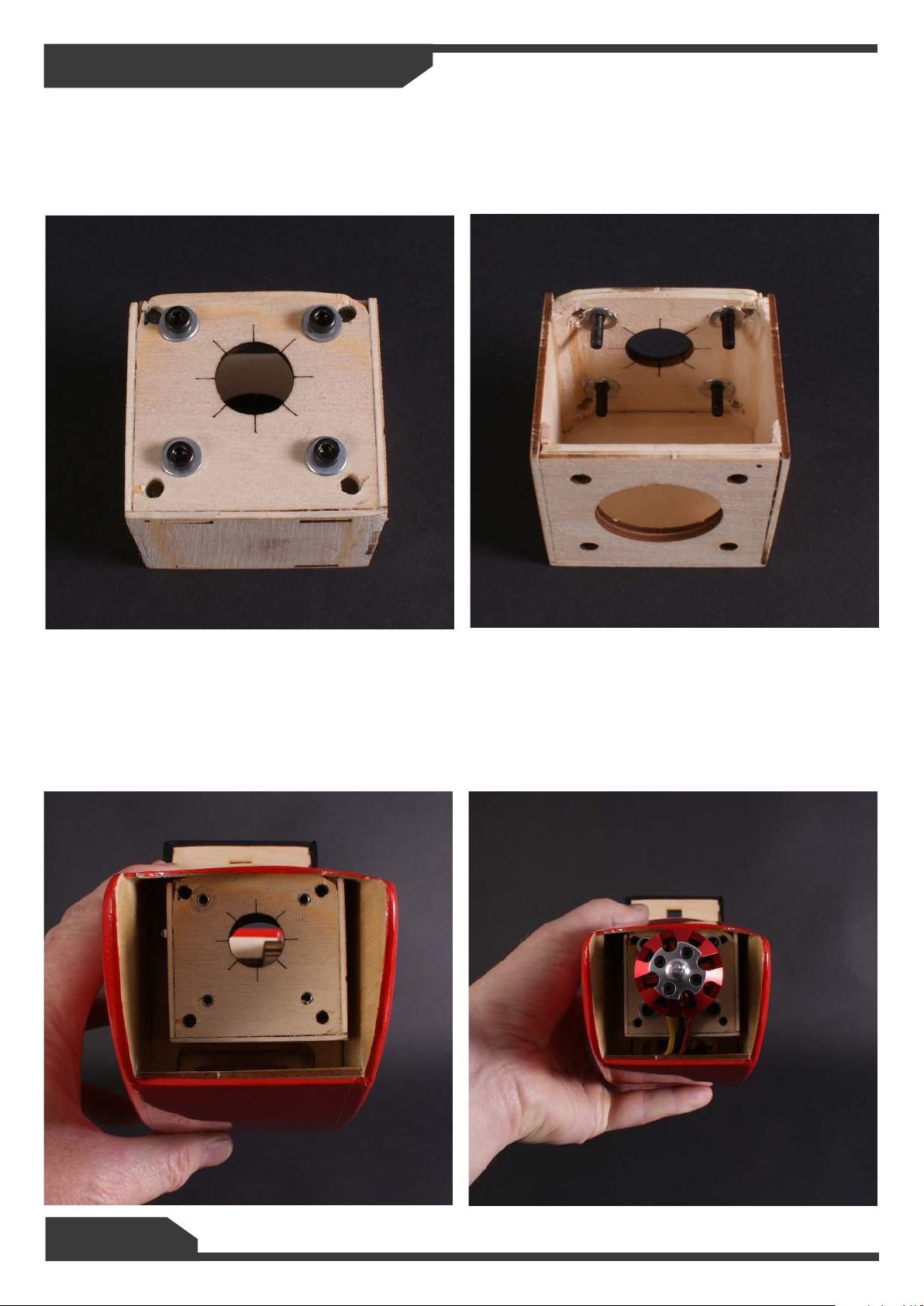
1. Take the plywood electric motor mount and drill 4 hole to suit your electric motor after marking and
aligning the motor on the mount. Using 4 x 3mm cap head bolts & washers t the captive nuts to the back
side of the plywood mount by tighten them together. Mix a little epoxy and apply this to the captive nuts to
help hold them in place.
2. Next you need to drill 4 access holes so that you t the motor mount to the front of the model.
These need to be just big enough to get your 4mm allen key through.
3. Now you can secure the assembly to the front bulkhead of the model using the supplied m4x14mm
cap head bolts and washers. Once mounted you can then t your motor. The wires should pass down
under the motor and in to the fuselage and connect to your speed controller.
Page 5
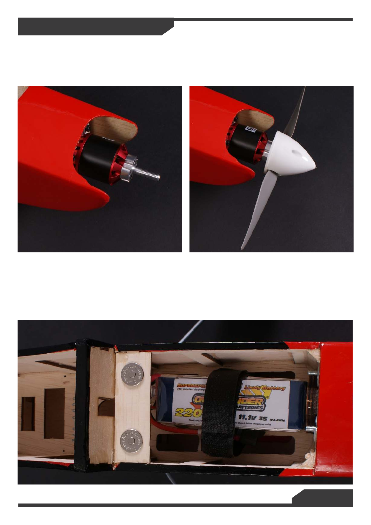
Building Your Max-Trainer
5. With you motor in place you can now t your propeller and spinner making sure everything is free to
rotate and does not foul on any part of the aircraft.
6. Fit the battery straps in to the battery tray. Cut a slot to t the speed-controller under the battery
tray.
7. If you want additional cooling to the battery you can remove the covering lm under the battery tray.
We did not need to do this on our prototype models.
Page 6
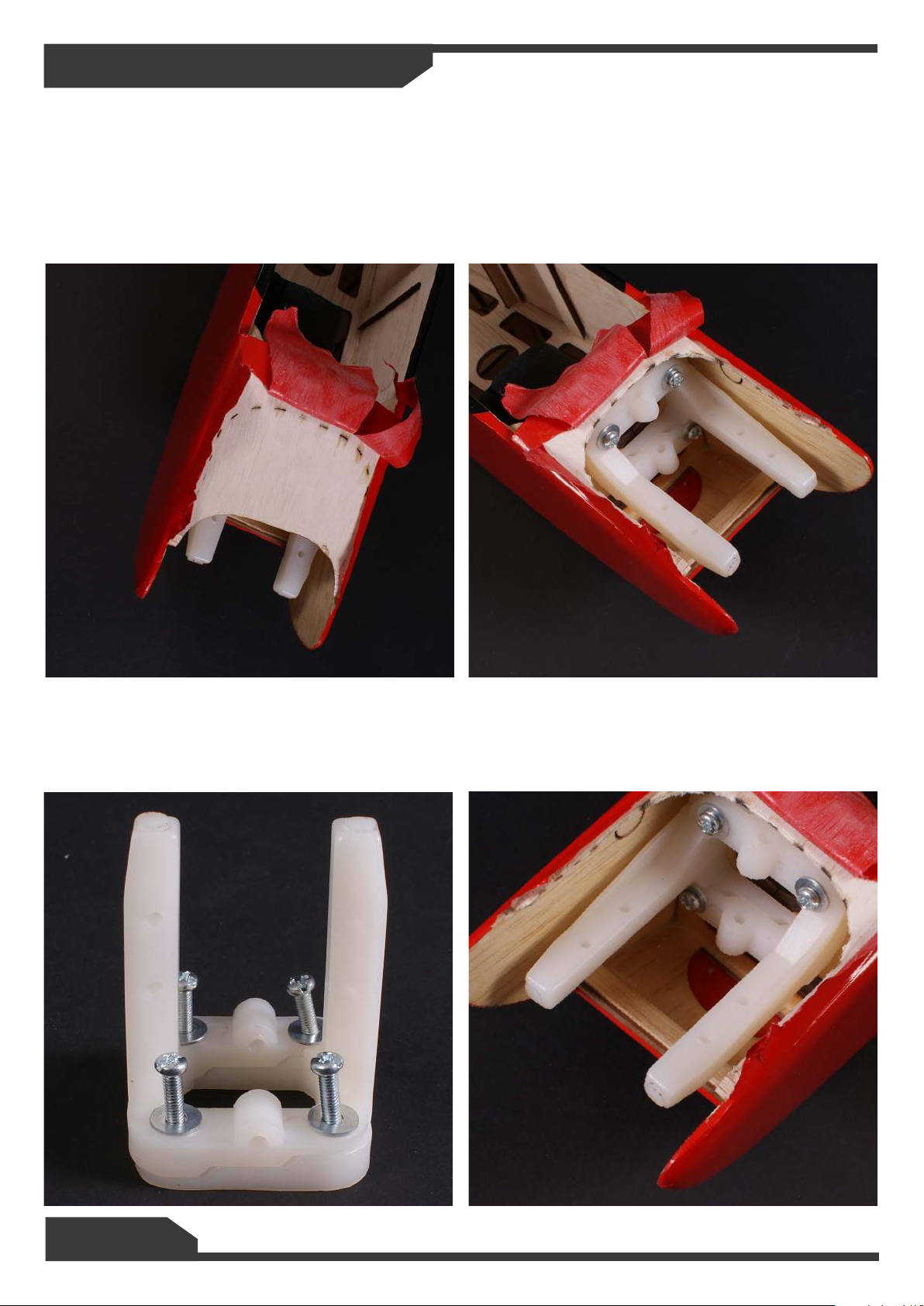
Building Your Max-Trainer
1. For the IC version you will rst have to remove the top pre lasered wooden panel to give access to
the motor bay. Peel the covering back and using a sharp modelling knife or Drexel cut away the top section
of wood following the pre lasered line. Once you have removed this section of wood you can re stick down
the lm using a covering iron or travel iron. At this stage you can also cover all the exposed edges of wood
in the engine bay with 5 minute epoxy to help fuel proof the area. Also remove the lm covering from the
oil drain hole under where the motor ts.
2. Loosely install the motor mount using the M4 x 25mm Philips head bolts and washer. The mount is
adjustable in width to suit various engines. Sit your engine on the mount and mount happy with the width
tighten up the bulk head bolts.
Page 7
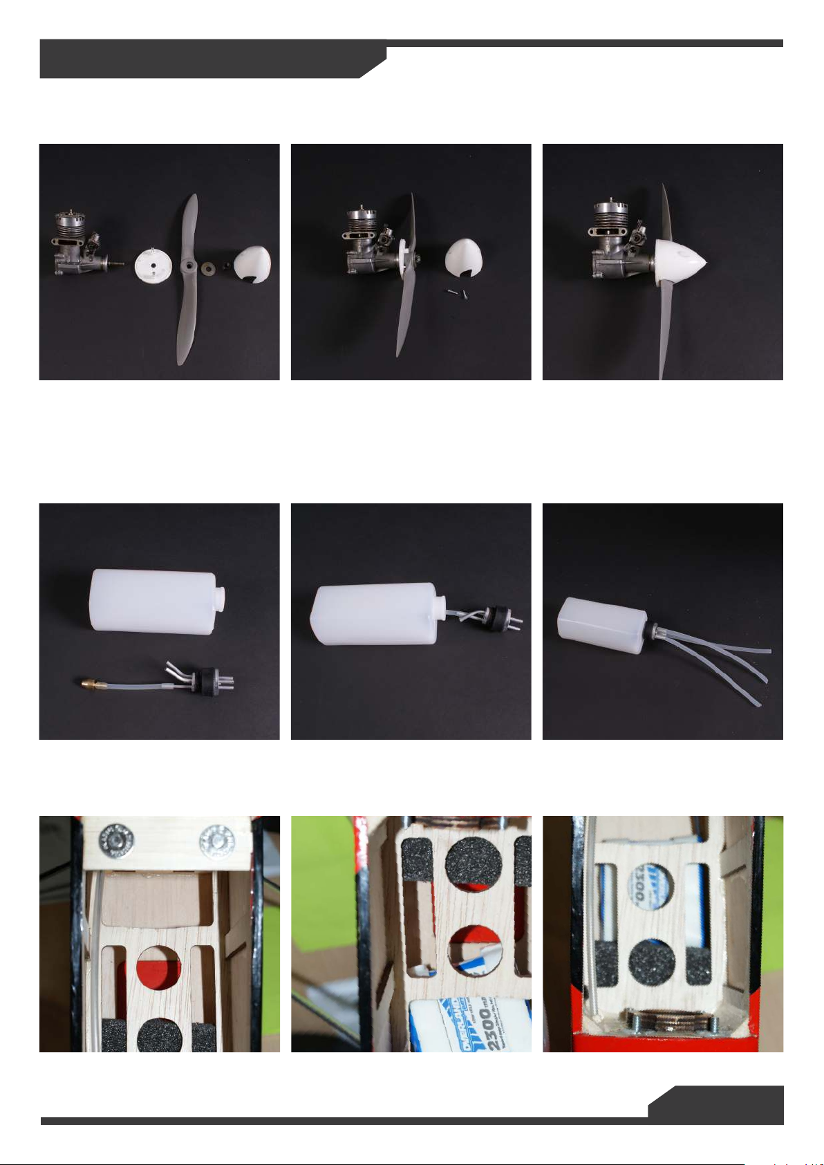
Building Your Max-Trainer
3. You now need to t your spinner and prop to the engine. Make sure it is tted correctly and is tight,
it is advisable to make sure the prop is balanced before you t it.
4. Assemble the fuel tank. Cut the fuel tube to 60-65mm and t the brass clunk and then gently bend
the vent and pressure tubes as shown in the photo. Push the assemble clunk on to the feed pipe. Fit the
bung assembly in to the tank making sure the vent/pressure pipes are pointing up and the clunk is free
to move around in side the tank and is not being restricted. Tighten the screw and t 3 lengths of pipe
approximately 150mm long to the outlets.
5. Lift the cabin from behind the mount to reveal the fuel tank bay. You can cut a slot into to the fuel
tank bay for your receiver battery to go under the fuel tank. Pack around the battery with foam to hold it in
place.
Page 8
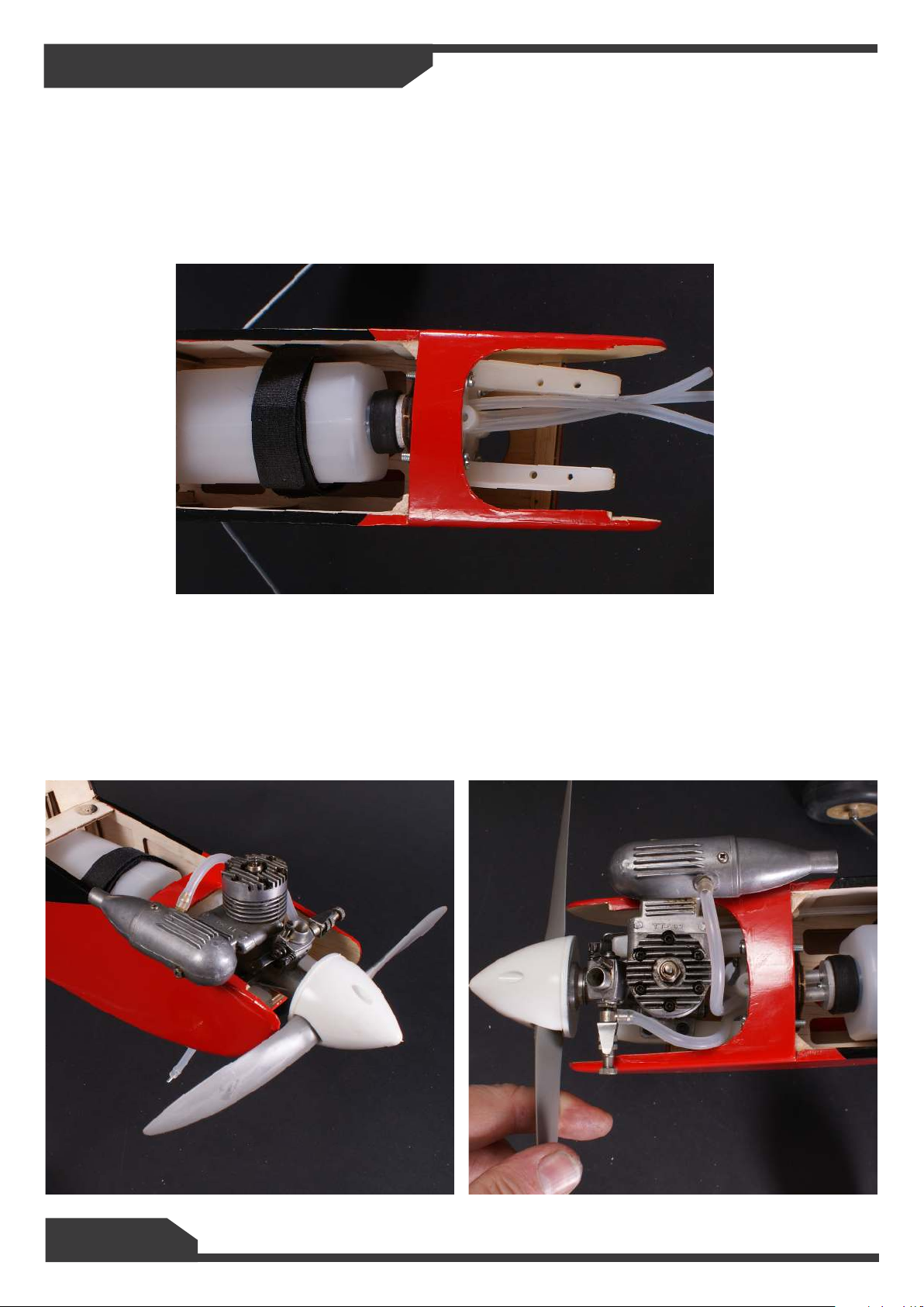
Building Your Max-Trainer
6. Install the fuel tank in to the fuselage and thread the pipes through to the engine bay. Secure the
fuel tank in to the bay using the Velcro strap.
7. Using the M3 x 25mm Cap head bolts, washers and nylock nuts t your engine to the mount. The
engine will look offset and this is intentional to help make the model y straight and level. Connect the
feed line to the carburettor and then one of the vent pipes to the exhaust. The other will be used to ll the
tank with fuel, this can be passed through the oil drain hole on the bottom of the fuselage, you will need a
method of plugging this line when in use. All three of these tubes can be cut to length to keep everything
tidy.
Page 9
Building Your Max-Trainer
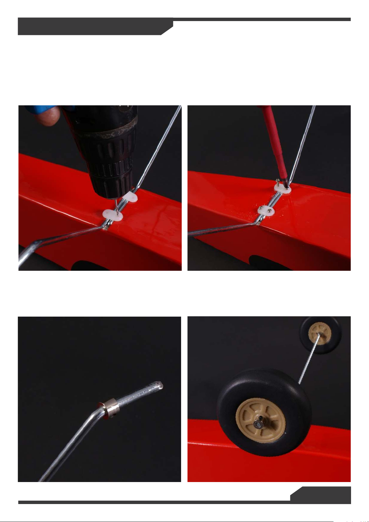
1. Install the landing main legs in to the bottom of the fuselage. Place the plastic saddle clamps in
place evenly and pilot drill 4 x 2mm holes for the self tapping screws. Screw M3x10 self tapping screws
through the saddle clamps in to the pilot holes and tighten rmly.
2. It is important to make sure the wheel spins freely on the axle so you may need to sand/le the
axles until the wheel slides on easily. First install one of the collets followed by a wheel and then the nal
collet. Tighten the grub screws to hold the wheel in place making sure the wheel will still spin.
Page 10
Building Your Max-Trainer
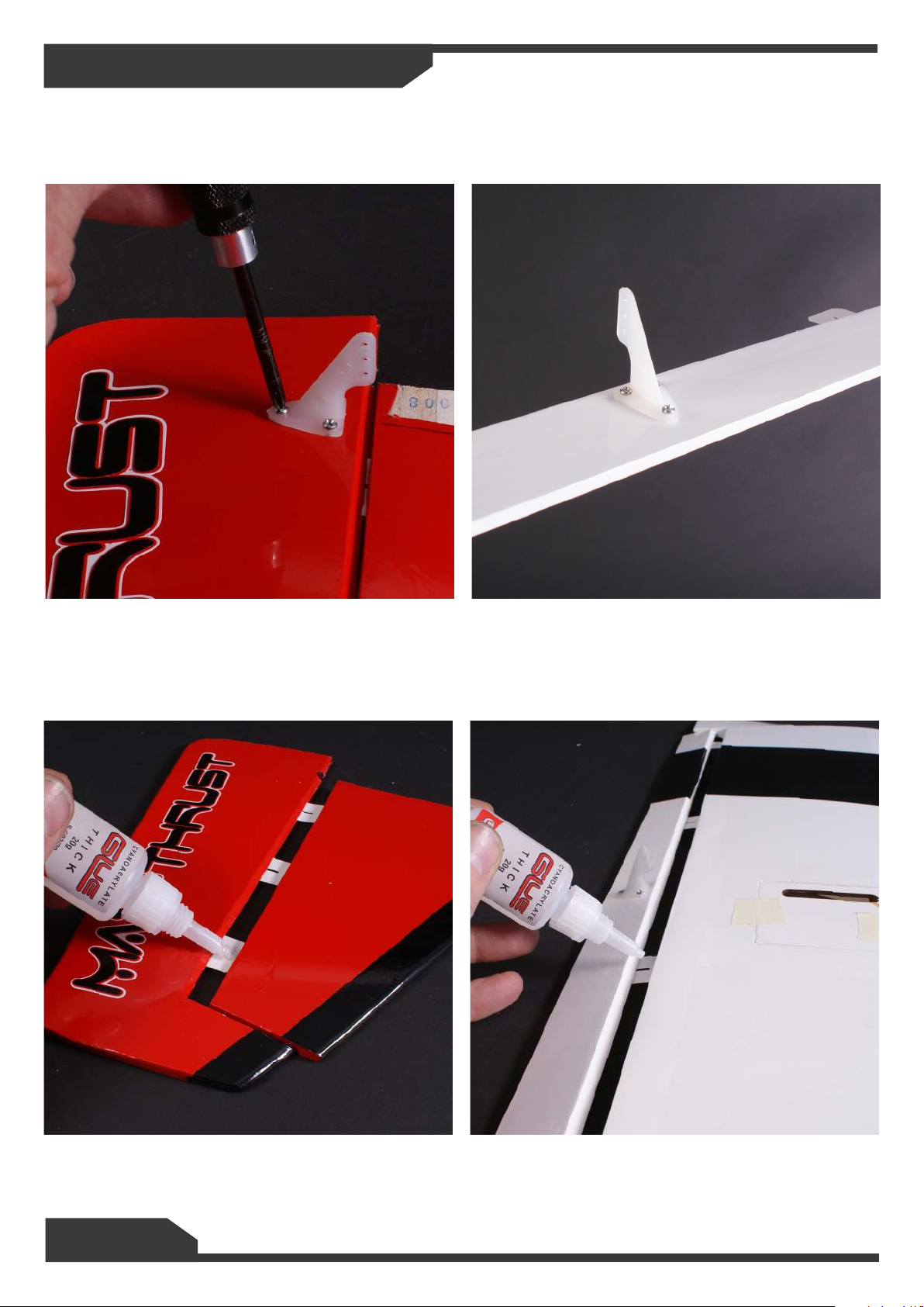
1. Fit the control horns to the n, elevator and ailerons using the M2x12mm self tapping screws and
plates.
2. All of the hinges on the rudder, tail plane and ailerons need glueing in to place. Slow or thick CA
Glue is best for this as it gives you a little time to apply and then to slide them in to place.
Page 11
Building Your Max-Trainer
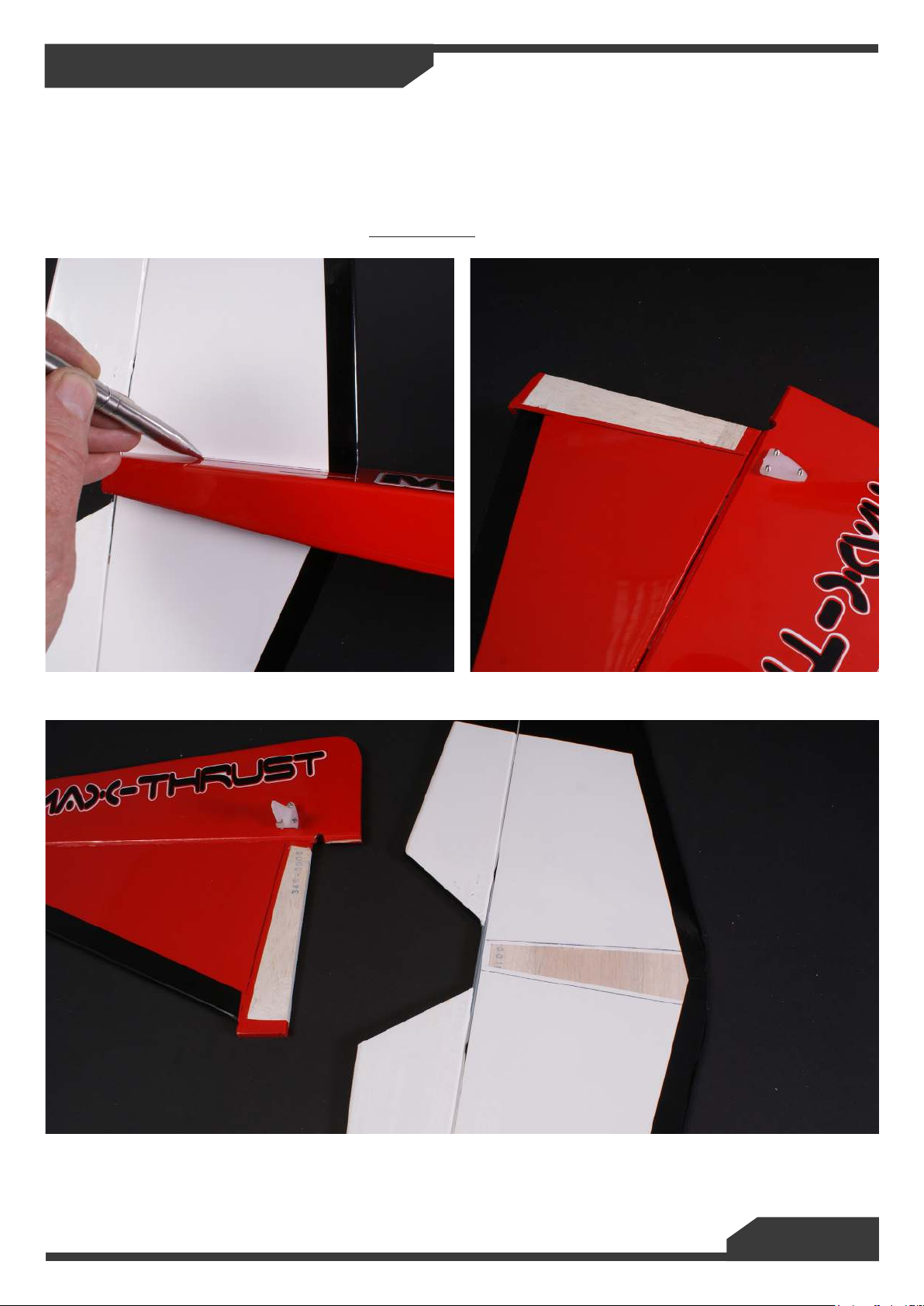
3. When tting the tail and n the covering needs to be removed so the 5minute epoxy can set hard
wood to wood. Slide the tail plane in to place making sure it is aligned and spaced correctly and mark the
position on the lm that needs to be removed using a pen on both the top and bottom. Slide the vertical
n in to place and mark the area of lm that needs to be removed. Using a sharp knife remove the
lm approx 1mm inside of the line, this gives a better nish. Be careful not to cut in to the tail or the n
structure as this will weaken the surface. Do not t yet.
Page 12
Building Your Max-Trainer
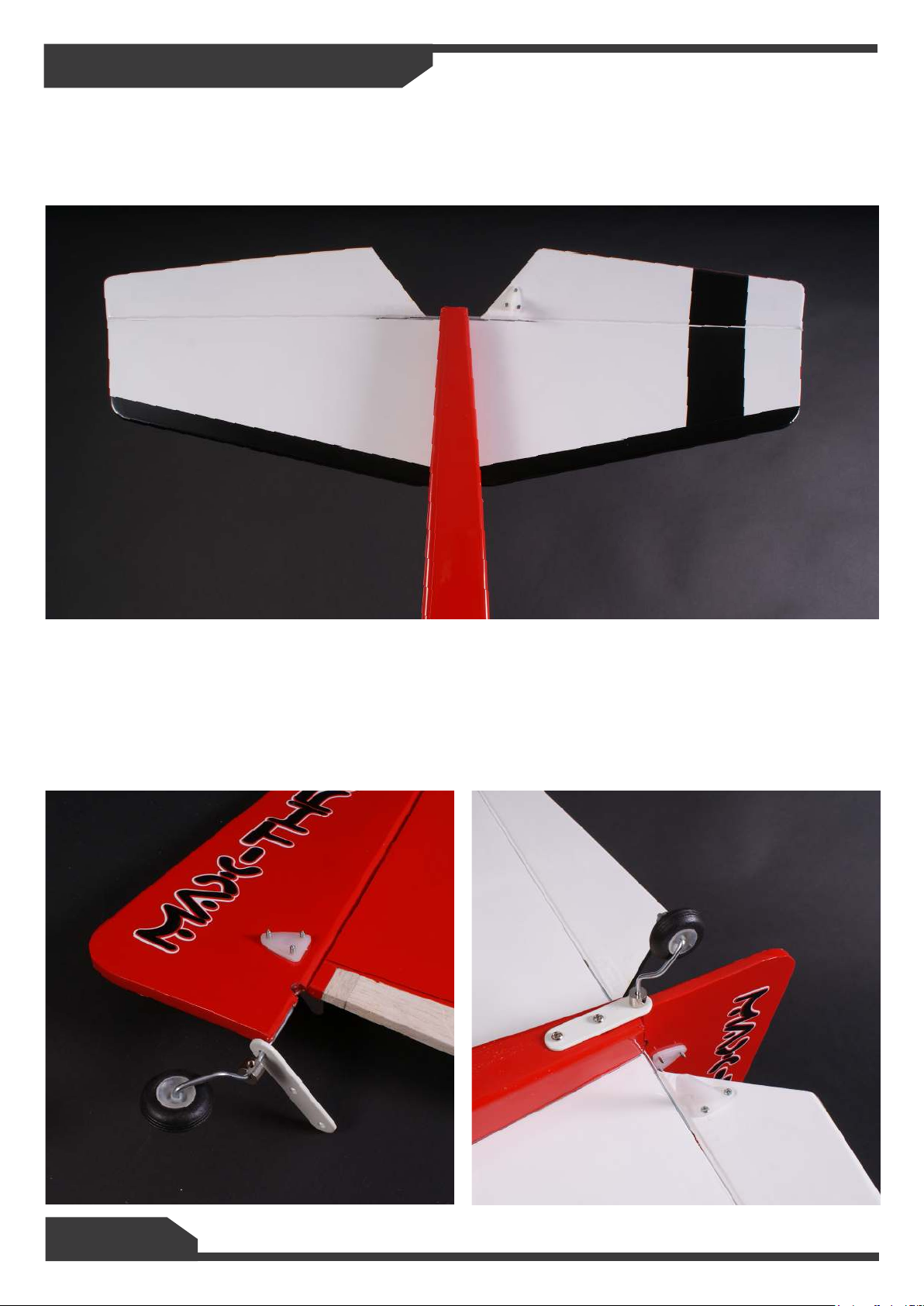
4. Test t the tail and make sure it is straight, remove and apply 5 minute epoxy to the tail slot on
the fuselage and then slide the tail plane back in to place. Secure in place so that it is square and even,
remove any excess glue and wait until the glue has fully set.
5. Put the tail wheel through the tail wheel bracket and glue with 5 minute epoxy in to the rudder.
Once dry offer the n to the slot tin the fuselage and make sure it is square. Remove and apply 5 minute
epoxy in to the slot and slide the n in to place. Secure and wait until fully set before drilling 2 2mm pilot
holes in to the fuselage to hold the tail wheel bracket in place. Screw on with 2 M3x10mm self tapping
screws.
Page 13
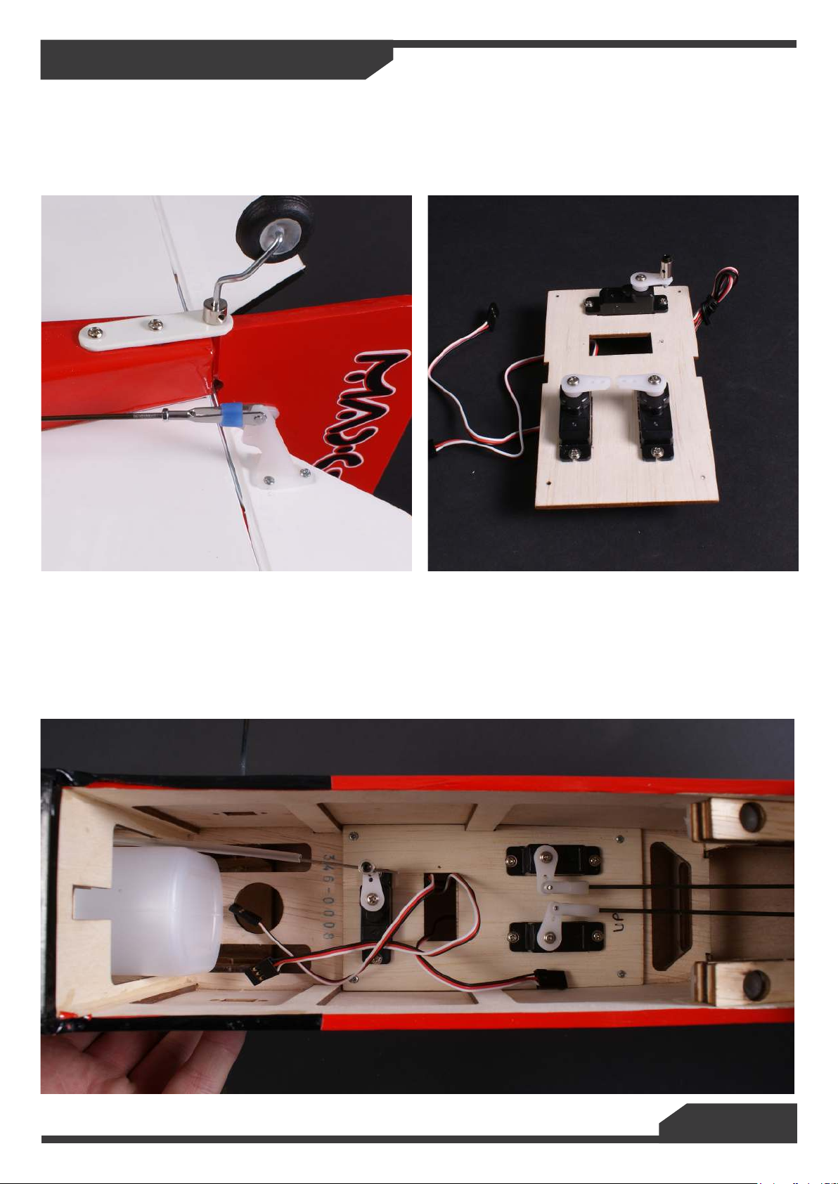
Building Your Max-Trainer
1. Rudder and elevator push-rods. Unscrew the metal quick links and slide the push-rods down the
tubes in the fuselage so that they exit to the rear of the fuselage. Reinstall the metal quick links.
2. Install the servos of your choice, prototype used 17g Mighty Mini servos from Century UK. If building
electric version you don’t need the throttle servo. Screw the servos in to the mount and then t this in to
the fuselage using the M2x12mm
3. Centre all the servos and then connect the elevator and rudder push-rods to the servos and install.
Once in position centre the elevator and rudder and then trim the push-rods to length leaving enough rod
(8mm) to bend the end 90 degrees to go through the servo horn and secure with swing keeper, if needed
you can adjust the quick links to get the control surface level.
4. IC ONLY Install the throttle control rod and connect to the carburettor. Trim the remaining rod to
length to suit your servo and slide it through the rod stopper screwed to the servo horn. Adjust and tighten
when happy you have full throttle control.
Page 14
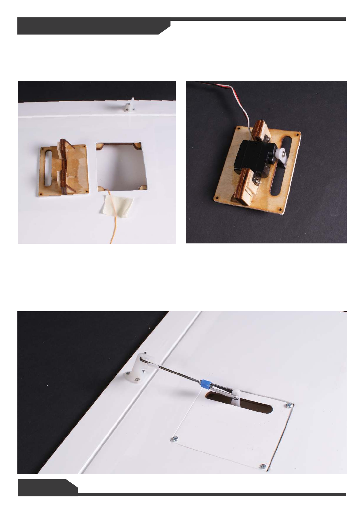
Building Your Max-Trainer
1. Take the servo trays out of the wings and adjust to suit your servos, our prototype used the Century
17g Mighty Mini servos with the 450mm leads. Fit the servos with the screws provided and make sure the
servo horn is centred and the output arm lines up with the centre of the slot. Some makes of servos may
need a little packing to get the output lined up.
2. Using the string provided pull the servo lead through the wing. You may need to use and servo
extension lead depending on your servo.
3. Put the assembly back in to the wing and secure with 4 m2x12mm self tapping screws.
4. Make up the servo push-rod and t using the swing keepers. Make sure the aileron is level when
the servo is centred.
5. Repeat for both wing halves.
Page 15
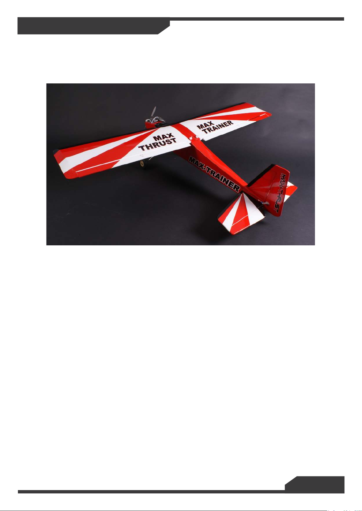
Building Your Max-Trainer
5. Join the 2 halves of the wing together using the metal tube spar, no glue is needed and this helps
with storage and transport.
6. Secure the assemble wing to the fuselage using the Nylon thumbscrews provided.
Final Setup.
Centre of Gravity.
The C of G is set between 7 - 8cm from the leading edge of the wing. This can be adjusted to suit after
initial ights. If you need to add nose weight do this under the motor mount as far forwards as possible
Control throws for rst ight.
Aileron 8 mm each way
Elevator 8 mm each way
Rudder 12 mm each way
You can increase these to suit your ying style after initial test ight are done.
Happy Flying and Landings, Mark Tilbury.
Page 16
Designed and Distributed by
Century UK LTD.
7 Anchor Business Park
Castle Road
Sittingbourne
KENT
ME10 3AE
United Kingdom
01795 437056
MADE IN VIETNAM
 Loading...