

MAXTHERMO MTC Series Manual
External power
supply
12VDC(15%), 80mA
Memory backup
EEPROM(overwrites: 100,000 times min.)that can store data for 10
years min.
Ambient
temperature
Operating: -10 to 55°C(with no icing or condensation)
Storage: -25 to 65°C(with no icing or condensation)
Ambient humidity 25% to 85%
MTC Series
Timer/Counter/Tachometer operation manual
3、
Model Number Legend
4、
Electric Specifications
Parameter name Timer Counter/Tachometer
Rated supply
voltage
100~24 0VAC(50/6 0HZ), 24VAC(50/ 60HZ), 24VDC( permiss ible
ripple: 20%(p-p)max.)
Operating voltage
range
85% to 110% rated supply voltage(24VDC; 90% to 110%)
Power consumption
Approx. 6.2VA at 264VAC, Approx. 5.1VA at 26.4VAC,
Approx. 2.4W at 24VDC
Input signals Signal, reset, gate CP1, CP2, Reset 1, Reset 2
Input method
No-voltage input/voltage input (switchable)
No-voltage input
ON impedance: 1kΩ max.(leakage current: 5~20 mA when 0Ω(
ON residual voltage: 3V max.
OFF impedance: 100kΩ min.
Voltage Input
High(logic) level: 4.5 to 30 VDC
Low(logic) level: 0 to 2 VDC
(Input resistance: approx. 4.7 kΩ)
※
◆
◆
Reset input Minimum input signal width: 1/20 ms(selectable, same for all input)
Sensor waiting time
250 ms max.(control output is turned OFF and no input is accepted
during sensor waiting time)
Output method Relay/transistor output
Control output
SPDT contact output: 5A at 250 VAC, resistive load(cosФ=1)
Minimum applied load: 10 mA at 5 VDC(failure level: P, reference
value)
Transistor output: NPN open collector, max. 100mA at 30 VDC
Residual voltage: 1.5 VDC max.(approx. 1V)
Output category according to EN60947-5-1 for timers with Contact
outputs
(AC-15; 250V 3A / AC-13; 250V 5A / DC-13; 30V 0.5A)
Out put cat egory a ccord ing to EN6 0947 -5-2 fo r t imer s w ith
Transistor outputs
(DC-13; 30V 100 mA)
NEMA B300 Pilot Duty, 1/4 HP 5-A resistive load at 120 VAC, 1/3
HP 5-A resistive load at 240 VAC
Parameter name Parameter Setting range (use key to select) Default value
Time range
--.--s/---.-s/----s/--min:--s/---.-min/
----min/--h:--min/---.-h/----h/-.---s
--.--s
Timer mode up/down up
Output mode a/a-1/a-2/a-3/b/b-1/d/e/f/z a
Output time hold/0000.01~9999.99 hold
Input signal width 20ms/1ms 20ms
NPN/PNP input
mode
npn/pnp npn
Key protection
level
kp-1/kp-2/kp-3/kp-4/kp-5 kp-1
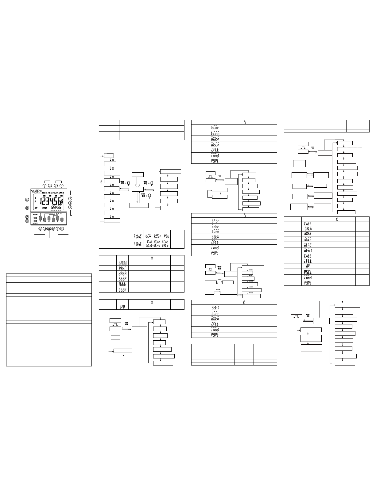
Twin Timer parameter setting
Run mode
Power ON
Function
setting mode
PV/OFF set time
PV/ON set time
OFF time range
ON time range
Timer mode
ON/OFF start mode
Input signal width
NPN/PNP input mode
Key protection level
3s min.
MODE
MODE
MODE
MODE
MODE
MODE
MODE
MODE
MODE
Parameter name
Parameter Setting range (use key to select) Default value
OFF time range
--.--s/---.-s/----s/--min:--s/---.-min/
----min/--h:--min/---.-h/----h/-.---s
--.--s
ON time range
--.--s/---.-s/----s/--min:--s/---.-min/
----min/--h--min/---.-h/----h/-.---s
--.--s
Timer mode
up/down
up
ON/OFF start
mode
toff/ton toff
Input signal width 20ms/1ms 20ms
NPN/PNP input
mode
npn/pnp npn
Key protection
level
kp-1/kp-2/kp-3/kp-4/kp-5 kp-1
2-Stage Timer parameter setting
Power ON
Run mode
Absolute value
Forecast value
Set value 1
Set value 2
Forecast set value
Set value
3s min.
Function
setting mode
Forecast/absolute value
Time range
Output mode
Input signal width
NPN/PNP input mode
Key protection level
Parameter name Parameter
Setting range (use key to select ) Default value
Forecast/
absolute value
ofst/abs ofst
Time range
--.--s/---.-s/----s/--min--s/---.-min/
----min/--h--min/---.-h/----h/-.---s
--.--s
Output mode a/f-1 a
Input signal width 20ms/1ms 20ms
NPN/PNP input
mode
npn/pnp npn
Key protection
level
kp-1/kp-2/kp-3/kp-4/kp-5 kp-1
Time parameter setting
Mode setting
1、
Safety Precautions
Do no t use the pr oduct wh ere corr osive or volatile gases are p resent, there ma y
occasionally be a risk of explosion.
Usable life of output r elay is determined by switch condition. According the actua l
usage, use product within its rated load and electrical life expectancy. If using product
beyond its life expectancy, its contacts may become fused or there may be a risk of
re.
This may occasionally cause electric shock, re or ma lfunction. Never disassemble,
repair or modify the product.
This may occasionally cause electric shock, re or malfun ction. Do not allow metal
fragments or lead wire scraps to fall inside this product.
Make sure that the supply voltage and signal connection is correct before power is
supplied, otherwise the product may be damaged.
Do not touch the input terminals or repair the product while power is supplied.This may
cause electric shock.
1.
2.
3.
4.
5.
6.
2、
Nomenclature
5、
Function parameter setting
1-stage counter
2-stage counter
Total counter
Run mode
Power ON
3s min.
Key protect switch
3s min.
3s min.
Transmission speed
Parity check
Date bit
Stop bit
Station address
Communication on/off
MODE
MODE
MODE
MODE
MODE
MODE
Batch counter
Dual counter
Tachometer
Twin timer
2-stage timer
Timer
★ Timer/ Counter/ Tachometer Selection Mode
Parameter name Parameter Setting range Default value
Timer/Twin Timer/2-Stage Timer
Selection Mode
/ /
tim
1-stage/ 2-stage / Total /Batch
/ Dual counter / Tachometer
Selection Mode
/ /
/
/
1cnt
★ Communication Format Function Selection Mode
Parameter name Parameter
Setting range (use key to select)
Default value
Transmission
speed
1200, 2400, 4800, 9600, 14400, 19200,
28800, 38400, 57600bps
9600
Parity check NONE/ODD/EVEN none
Date bit 8-bit/7-bit 8-bit
Stop bit 1-bit/2-bit 1-bit
Station address 01~FF (HEX) 01
Communication
on/off
ON/OFF on
★ Key Protection Setting Mode
Parameter name Parameter Setting range (use key to select) Default value
Key protection
switch
off/on off
Timer parameter setting
Run mode
Power ON
Function
setting mode
PV/SV
PV/ON duty ratio
PV/cycle
Time range
Timer mode
Output mode
Output time
Input signal width
NPN/PNP input mode
Key protection level
3s min.
Timer (except for Z mode)
MODE
MODE
MODE
MODE
MODE
MODE
MODE
MODE
MODE
Timer (Z mode)
Counter parameter setting
Function setting
mode
Run mode
Power ON
Present value,
set value 1
Present value,
set value 2
3s min.
1-stage counter
Present value
set value
2-stage counter
CP1 present value
CP2 present value
MODE
Dual counter
Dual count value,
dual count set value
Input mode
Dual count calculating mode
Output mode
One-shot output time
One-shot output 2 time
One-shot output 1 time
MODE
MODE
MODE
MODE
MODE
MODE
Counting speed
Input signal width
Decimal point position
Prescale value
NPN/PNP input mode
Key protection level
MODE
MODE
MODE
MODE
MODE
Present value,
set value
Total set value
MODE
Total and preset counter
Present value,
set value
Batch count value,
batch count set value
Batch counter
MODE
MODE
MODE
Tachometer parameter setting
Function setting
mode
Run mode
Power ON
3s min.
Tachometer output mode
Counting speed
Decimal point position
Prescale value
Average processing
Auto-zero time
MODE
MODE
MODE
MODE
MODE
MODE
Startup time
Measurement value
Measurement value
OUT1 set value
NPN/PNP input mode
Key protection level
MODE
MODE
MODE
MODE
MODE
Measurement value
OUT2 set value
MODE
Parameter name Parameter
Setting range (use key to select)
Default value
Input mode up/down/ud-a/ud-b/ud-c (See note 1.) up
Dual count
calculating mode
add/sub (See note 1.) add
Output mode n/f/c/r/k-1/p/q/a/k-2/d/l/h (See note 2.) n
One-shot output
time
000.001~999.999 000.500
One-shot output
2 time
000.001~999.999 000.500
One-shot output
1 time
hold/000.001~999.99 (See note 3.) hold
Counting speed 30Hz/5KHz 30hz
Input signal width 20ms/1ms 20ms
Decimal point
position
----/---.-/--.--/-.--- ----
Prescale value 000.001~999.999 001.000
NPN/PNP Input
mode
NPN/PNP NPN
Key protection
level
kp-1/kp-2/kp-3/kp-4/kp-5 kp-1
Note: 1.The setting range varies with the output mode.
2.The setting range varies with the model and the input mode.
3.HOLD can not be set when the output mode is K-2.
Setting range Unit Default value
0000.00~9999.99 (Time range: -.-s) s 0000.00
00000.0 ~ 99999.9 (Time range: -.-s) s 00000.0
000000 ~ 999999 (Time range: --s) s 000000
0000:00 ~ 9999:59 (Time range: -min-s) min:s 0000:00
00000.0 ~ 99999.9 (Time range: -.-min) min 00000.0
000000 ~ 999999 (Time range: --min) min 000000
0000:00 ~ 9999:59 (Time range: -h-min) h:min 0000:00
00000.0 ~ 99999.9 (Time range: -.-h) h 00000.0
000000 ~ 999999 (Time range: --h) h 000000
000.000 ~ 999.999 (Time range: -.-s) s 000.000
Set Value (Range) A, B
Display
Key Protection Indicator
Mode Key
(changes modes and
setting items)
Reset Key
(resets present value and
output)
Reset Indicator Control Output Indicator
Set Value
(character height: 4 mm)
Present Value
(character height: 9 mm)
Time Unit Display
(If the time range is
0min, 0.0 m in, 0 h,0.0h,
0h :0 m, th is di sp l ay
ashes to indicate timing
operation)
The Fifth Setting Key
The Fourth Setting Key
The Sixth Setting Key
The Second Setting Key
The Third Setting Key
The First Setting Key
MTC – 3 1 2 1 – A
A B C D E F
A.Maxtech:Timer / Conuter/ Tachomer
B.Functions: 3- Timer / Conuter/ Tachomer all in 1
C.Output type: 1-Relay 2-Transistor
D.Communiction: 1-No Communiction 2-RS-232 3-RS-422 4-RS-485
E.Installation: 1-DIN rail 2-48x48mm panel
F.Voltage:A-AC100~240V, 50/60 Hz D- DC24V / AC24V
UP DOWN UP/DOWN A, B, C
Output
mode
setting
K-1
P
Q
A
UP/DOWN A, B, C
Output
mode
setting
K-2
D
L
H
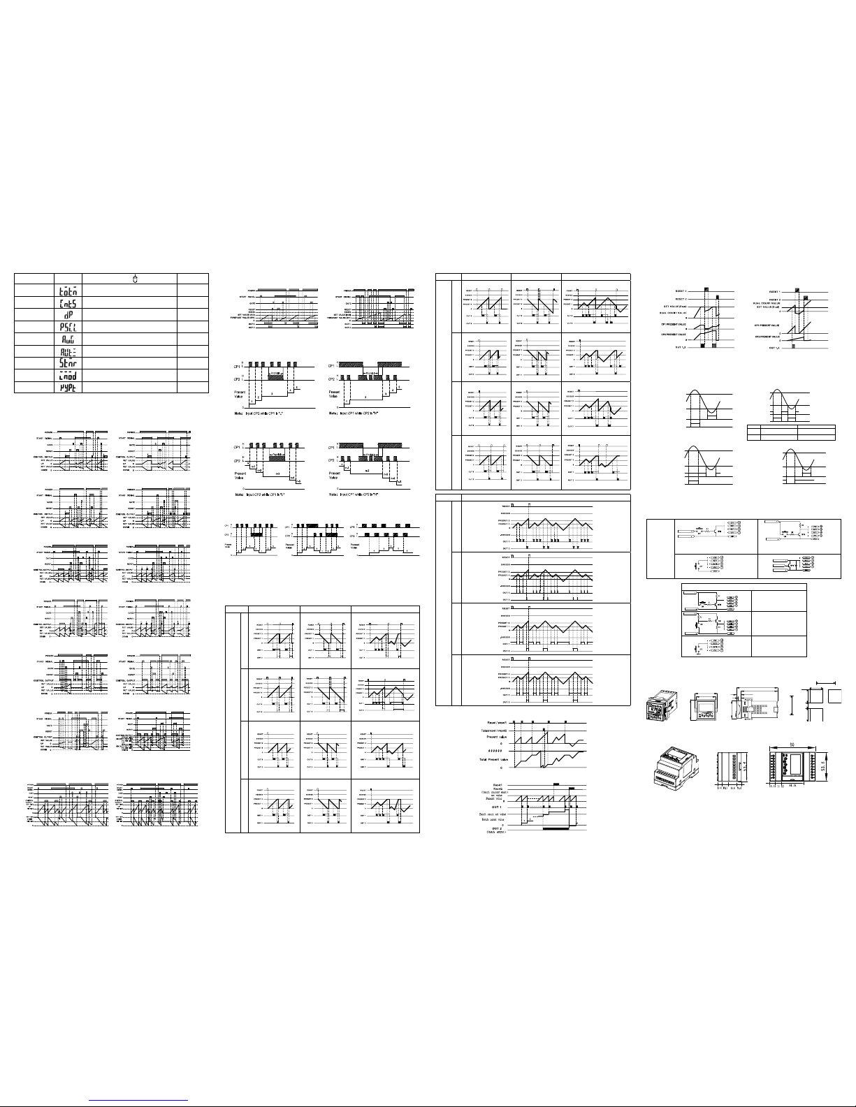
★
Total and Preset Counter Operation
★
Batch Counter Operation
6、
Sequence Charts
Output mode A: signal ON delay 1
Output mode A-1: signal ON delay 2
Output mode A-2: Power ON delay 1 Output mode A-3: Power ON delay 2
Output mode b: Repeat cycle 1
Output mode b-1: Repeat cycle 2
Output mode d: Signal OFF delay
Output mode E: Interval
Output mode F: Cumulative
Z mode : ON/OFF –duty adjustable icker
★
Timer Operation
Output Mode toff: icker OFF start
Output Mode ton: icker ON start
★
Twin Timer Operation
★
2-Stage Timer Operation
A Mode: Signal ON delay F-1 Mode: Cumulative
★
Counter Input Modes and Present Value
UP / DOWN A
command input mode
UP / DOWN B
individual input mode
UP / DOWN C
quadrature input mode
UP (increment) Mode
CP1: count input
CP2: prohibit(gate)input
UP (increment) Mode
CP1: prohibit(gate)input
CP2: count input
DOWN(decrement) mode
CP1: count input
CP2: prohibit(gate)input
DOWN(decrement) mode
CP1: prohibit(gate)input
CP2: count input
★
Counter Output Mode Setting
Operation for 1-stage models is the same as that for OUT2.
When using a 2-stage model as a 1-stage counter, or dual counter, total and preset counter, OUT1 and
OUT2 turn ON and OFF.
UP DOWN UP/DOWN A, B, C
Output
mode
setting
N
F
C
R
★
Dual Counter Operation
Dual Count Calculating Mode = ADD
Dual count value = CP1 PV + CP2 PV
Dual Count Calculating Mode = SUB
Dual count value = CP1 PV -CP2 PV
★
Tachometer Output Mode Settings
Measurement value
(Lower-limit)
OUT1 set value
(upper-limit)
OUT1 set value
OUT 1
OUT 2
ON condition for OUT1: measurement value≤OUT1 set value
ON condition for OUT2: measurement value≥OUT2 set value
OUT2 set value
Measurement value
OUT1 set value
Condition
OUT1 ON
OUT2 ON
OUT1 set value≤OUT2 set value
OUT set value≤Measurement value≤
OUT2 set value
Measurement value<OUT1 set value
Measurement value >OUT2 set value
Measurement value <OUT2 set value
Measurement value >OUT1 set value
OUT1 set value >OUT2 set value
OUT2 set value≤Measurement value≤
OUT1 set value
OUT 1
OUT 2
(Upper-limit)
OUT2 set value
Measurement value
(Lower-limit)
OUT1 set value
OUT 1
OUT 2
(Upper-limit)
OUT2 set value
Measurement value
(Lower-limit)
OUT1 set value
OUT 1
OUT 2
ON condition for OUT1: measurement value≥OUT1 set value
ON condition for OUT2: measurement value≥OUT2 set value
ON condition for OUT1: Measurement value≤OUT1 set value
ON condition for OUT2: Measurement value≤OUT2 set value
7、
Input Connections
TC-Pro482 Timer/Counter/Tachometer operation manual
8、
Dimensions and Panel Cutouts
Note: M3 terminal screw (effective length: 8mm)
No-voltage
Inputs
(NPN Input)
External voltage
External voltage
Gate CP1
Signal CP2
Reset 1
Reset 2
Open Collector
(connection to NPN open collector output
sensor)
External voltage
External voltage
Gate CP1
Signal CP2
Reset 2
Reset 1
Voltage Inputs
(connection to a voltage output sensor)
Gate CP1
Signal CP2
Reset 2
Reset 1
Contact Input
External voltage
External voltage
Internal circuit
Gate CP1
Signal CP2
Reset 2
Reset 1
Two-wire Sensor
Voltage Inputs (PNP Input)
External voltage
External voltage
Gate CP1
Signal CP2
Reset 2
Reset 1
No-contact Input
(NPN Transistor)
(Connection to NPN open
collector output sensor)
External voltage
External voltage
Gate CP1
Signal CP2
Reset 2
Reset 1
No-contact Input
(PNP Transistor)
(connection to a voltage
output sensor)
Gate CP1
Signal CP2
Reset 2
Reset 1
Contact Input
Parameter name Parameter Setting range (use key to select) Default value
Tachometer
output mode
hilo/area/hihi/lolo hilo
Counting speed 30Hz/10KHz 30Hz
Decimal point
position
----/---.-/--.--/-.--- ----
Prescale value 000.001~999.999 001.000
Average
processing
off/2/4/8 off
Auto-zero time 00.01~99.99 99.99
Startup time 00.01~99.99 00.00
NPN/PNP
Input time
NPN/PNP NPN
Key protect level kp-1/kp-2/kp-3/kp-4/kp-5 kp-1
60.25
110.5
98
12.5
7.25
53
48
55.5
65 mm 以上
20 mm 以上
45 mm
65 mm 以上
45 mm
45 mm
+ 0.6
- 0
+ 0.6
- 0
+ 0.6
- 0
 Loading...