

Page 1

RFID Reader User’s Guide
Version
V11.11
Author R & D Dept.
This User’s Guide is for salesperson, installing and techn ical supp ort person of RFID Reader, in order to
make them understand the installing and testing of our readers clearly. Before operating the reader,
please read the guide carefully.
Page 2

1
CATALOG
1. BRIEF INTRODUCTION ............................................................................................................................... 2
1.1 PRODUCT PERFORMANCE .......................................................................................................................... 2
2. INSTALLATION & CONNECTION .............................................................................................................. 3
2.1 INSTALLATION & POWER SUPPLY .............................................................................................................. 3
2.2 C
ONNECT TO PC & CONTROLLER .............................................................................................................. 3
3. WORKING MODE ......................................................................................................................................... 4
3.1 MASTER-SLAVE MODE .............................................................................................................................. 4
3.2 T
RIGGER/AUTOMATIC MODE .................................................................................................................... 4
4. COMMUNICATION PORT ............................................................................................................................ 5
CONNECT TO PC ..................................................................................................................................................... 6
4.1 C
ONNECT TO CONTROLLER ....................................................................................................................... 6
4.2 C
ONNECT TO TRIGGER & GPIO................................................................................................................. 6
5. FAQ .................................................................................................................................................................. 8
Page 3
2
1. Brief Introduction
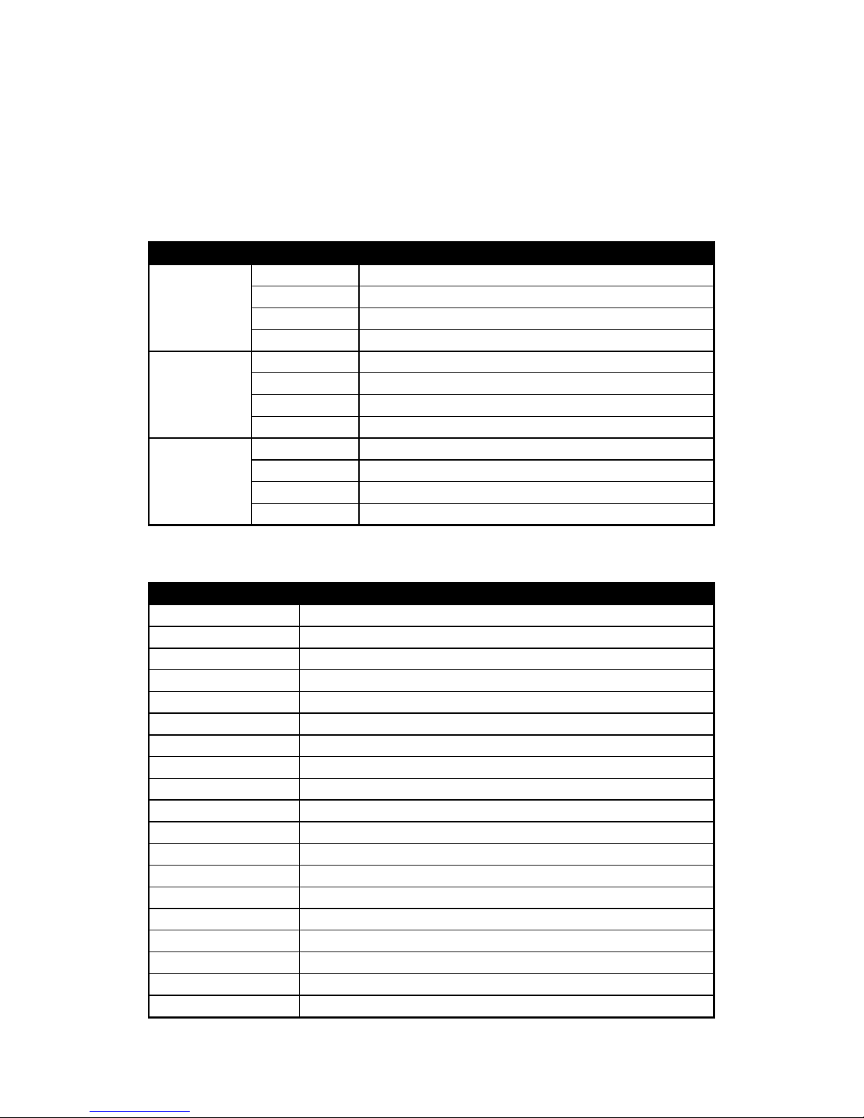
RFID Reader is one of our developed RFID Readers for UHF Electron ic Tags. It supports ISO18000-6 B
and EPC Class1 Gen2 protocol so that to read and write the relative tags. With perfect performance and
easy operation, it can be integrated in many applications listed below:
Application Examples Description
Vehicle
Management
Parking lot Charge automation, pass in and out management
Highway Charge Charge automation for highway, bridge and tunnel
Dock/Container Container management in road, railway and dock
Vehicle Monitor Vehicle monitor in traffic management
Logistics
Management
Warehouse Warehouse, Super market, Mailing, Package management
Manufacture Monitor the products in production-line
Custom Goods management for custom clearance
Anti-fake Anti-fake for products
Staff Management Access Control Access control system for staff pass in and out
Work Attendance Check on work attendance, HR management
Miner Miner management, insurance
EduToHome Students management between school and home
1.1 Product Performance
Item Parameters & Performance
Reader-Tag Protocol ISO18000-6B, EPC Class1 Gen2
Antenna Port Integrated antenna, Circular Polarization
Frequency Band US(902-928MHz)
Frequency Mode Fixed frequency mode(915MHz)
Communication RS232/USB/LAN, RS485/Wiegand/GPIO
Identify Tag Range Read 0 - 15M, depended on environment and tag
-- - -
Software Support Provide Windows API, Demo software with source code
Power Supply DC 12V supply, less than 2A
Dimension 440x440x80 mm (not including fitting)
Weight 4.0Kg
Pole Diameter 60-70mm
Storage Temp -30 ~ +85 degree celsius
Operation Temp -20 ~ +80 degree celsius
Anti-thunder Protection Shell direct to the ground, communication 1.5KV surge endurance
Work Performance High speed micro-processor controlled, running steadily
Work Mode Support Master-Slave mode, Trigger/Automatic mode
Fast Identify Tags with more than 160Km/h speed can be identified
Upgrade Firmware can be upgraded easily by RS232/USB/LAN
Page 4

3
2. Installation & Connection
The reader must be installed and connected correctly before operating. First you sh ould connect power
supply and antenna before connecting PC or controller.
2.1 Installation & Power Supply
The reader can be simply installed. Please adjust the fixture to a suitable angle according to your
application.
The maxmium distance between the reader and host varys from data port types. The reliable
communication distance is 10m for RS232, 5m for USB, 15m for Wiegand, 100m for LAN, and 1.0KM for
RS485. Exceeding the above distances is not suggested.
The power input of this reader is 12V DC. An AC to DC adaptor is offered. Plug the adaptor into DC
connector of reader before operating. If the reader makes a sound of a long B eep, the power input is
normal.
2.2 Connect to PC & Controller
The reader can be connected to PC by RS232, USB(need a RS232 T o USB Converter). (For detail
please see Part 4. Communication Port.)
The reader can be connected to controller by RS485 or WIEGAND. It can realize input / output operation
and response to outer trigger or GPIO port(not lead out by default). (For detail please see Part 4.
Communication Port.)
Page 5

4
3. Working Mode
The reader can identify working modes automatically and make corresponding response.
3.1 Master-Slave Mode
Under Master-Slave working mode, readers must be controlled by host machine (PC or controller). It
receives the command from host, executing read/write actions on tags, and responsing the data to the
host. Before receiving command from host, reader will stay idle.
We provide SDK software package for reader. This kit package includes Serial Port Communication
Protocol, API functions set and Demo sample program. API functions set and Demo sample program is
for PC to communicate with reader, while Serial Port Communication Protocol is for Controller to
communicate with reader.
3.2 Trigger/Automatic Mode
Under Trgger/Automatic working mode, reader will detect tag automatically in periodical time. After that, it
will response data to the host. In this mode reader does not need to wait command from the host.
Page 6
5
4. Communication Port
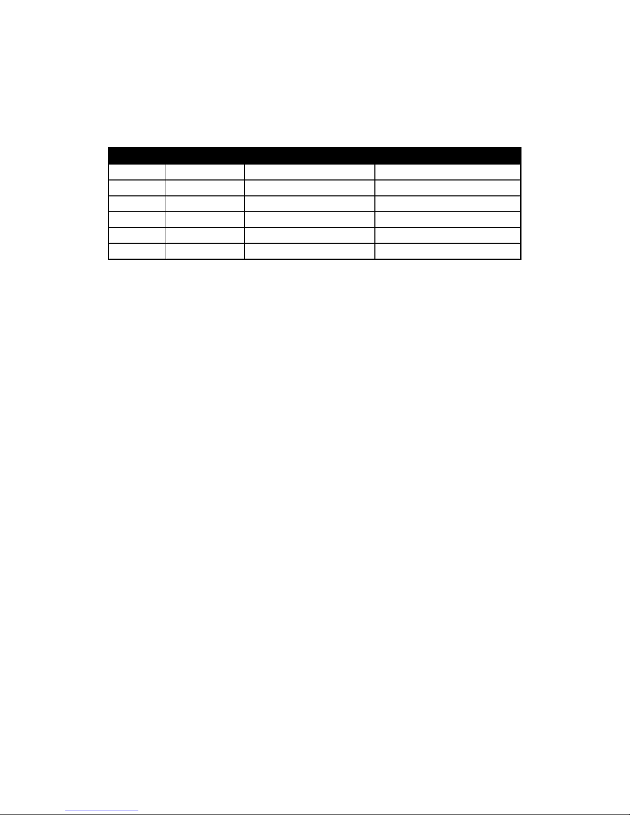
The reader has kinds of communication ports. It can communicate with PC or controller that has standard
RS232,RS485 or Wiegand port. The communication ports of the reader include:
Port Name Port Type Port Qty. Application
TRIGGER IN 1 Pcs Connect Reader to outer Relay
RS-485 A+,B- 1 Group Connect Reader to Controller
WIEGAND D0,D1 1 Group Connect Reader to Controller
RS-232 DB9 Female Port 1 Pcs Connect Reader to PC
LAN RJ45 Port 1 Pcs Connect Reader to PC/HUB
GPIO GPI, GPO Optional, not lead out by default General Input/Output
Page 7
6
Connect to PC
The reader can be connected to PC by RS232 or LAN.
RS232
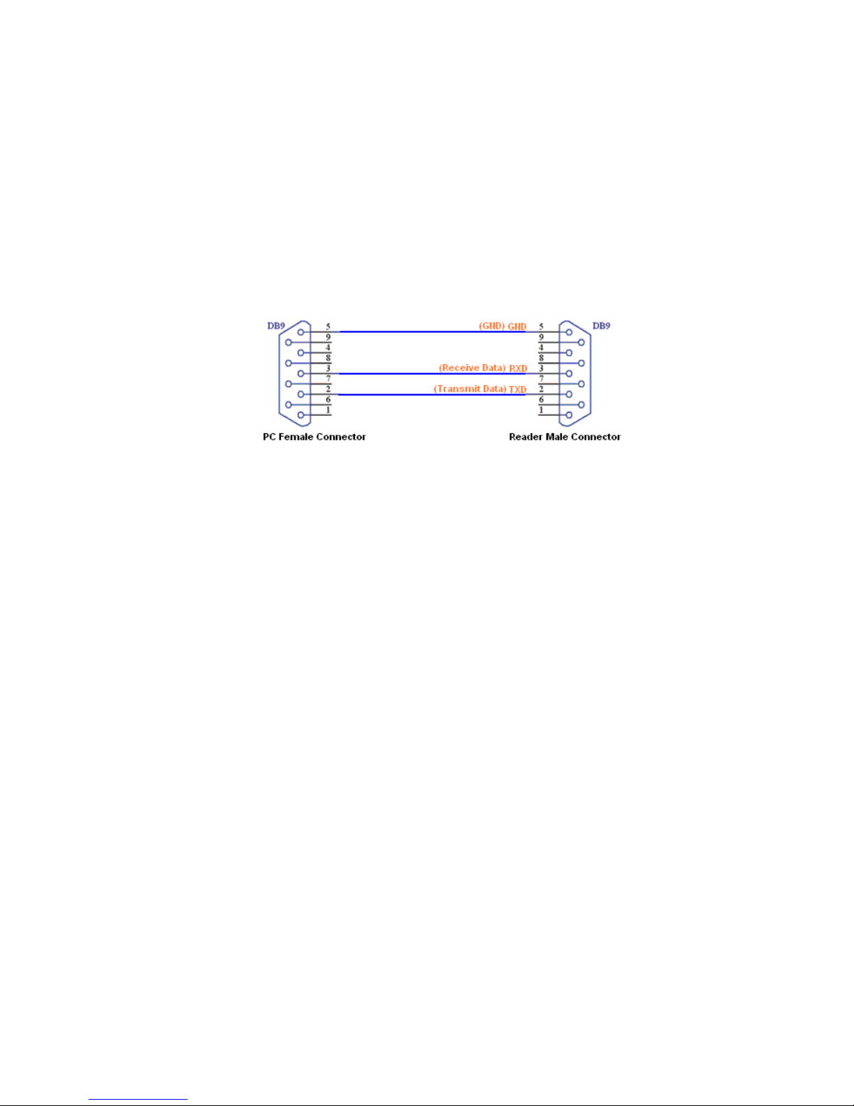
The reader has a DB9 RS232 port which is usually connected to PC for communication. Directly connect
RS232 of reader to the COM port of PC with DB9 Female cable. The inner connecting relationship is
illustrated below:
4.1 Connect to Controller
The reader can be connected to controller by RS485 or WIEGAND.
RS485
The reader has a RS485 connector, which is usually used for connection b etween reader and co ntroller.
It can be intergrated to RS485 network or connected to PC through a converter. RS485 should be a twist
masked cable, with 1000m of reliable communication distance. RS485 cable consists of two difference
signal wires: RS485A+(A+) and RS485B-(B-).
Wiegand
The reader has a Wiegand connector, which is usually used for connection between reader and controller.
Wiegand should be a twist masked cable, within 10m of reliable communication distance. Wiegand cable
consists of three signal wires: Data0(D0), Data1(D1) and Ground(GND). Please make sure the good
connection to the ground.
4.2 Connect to Trigger & GPIO
The reader can response outer trigger. It can realize input/output by GPIO, too.
Trigger
In Trigger connection, you should touch IN to GND by outer trigger. For example, you may add a relay to
realize a trigger from ground sensor or key-pressing. The suggeste d connecting method is illustrated
below:
Page 8

7
GPIO
Note: By default we do not give GPIO, user may ask us to customize them if needed.
In GPIO connection, you should connect GPO(Output) and GPI(Input) to the outer equipment. T he GPO
could be connected to outer equipment(eg. Relay) to drive the barrier or light.
Page 9
8
5. FAQ
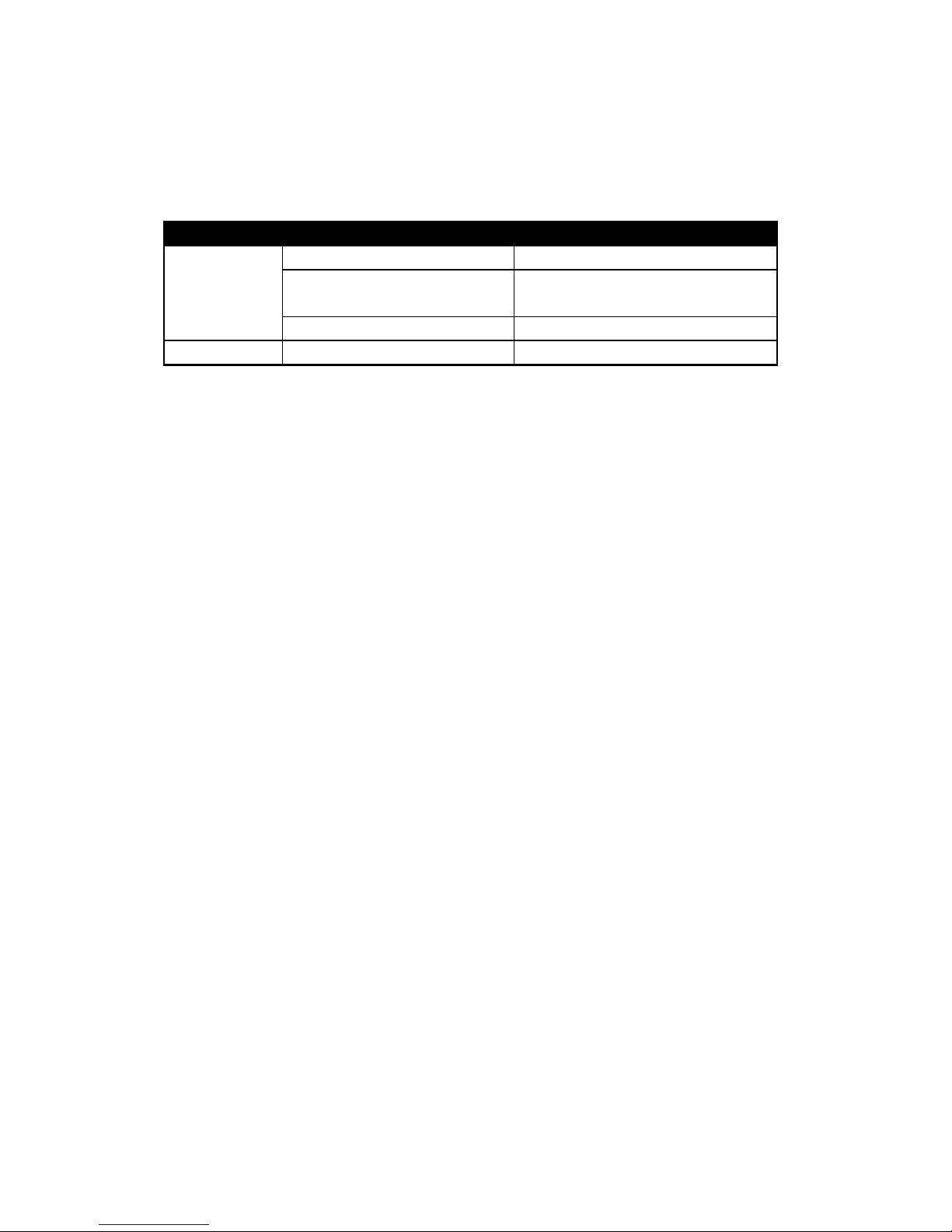
The frequent asked questions and the resolutions are listed below:
Failure Possible Reason Solution
Tag unreadable Tag is too far from antenna Move the tag close to antenna
Tag direction does not match the antenna
polarization
Please face tag to antenna, and keep the correct
polarization
Tag has been damaged Change a new tag
Power does not work Poor contact for power plug Check the power supply, use the correct power
FCC Warning
This equipment has been tested and found to comply with the limits for a Class B digital device, pursuant
to part 15 of the FCC Rules. These limits are designed to provide reasonable protection against harmful
interference in a residential installation. This equipment generates, uses and can radiate radio frequency
energy and, if not installed and used in accordance with the instructions, may cause harmful interference
to radio communications. However, there is no guarantee that interference will not occur in a particular
installation. If this equipment does cause harmful interference to radio or television recep tion, which can
be determined by turning the equipment off and on, the user is encouraged to try to correct the
interference by one or more of the following measures:
• Reorient or relocate the receiving antenna.
• Increase the separation between the equipment and receiver.
• Connect the equipment into an outlet on a circuit different from that to which the receiver is connected.
• Consult the dealer or an experienced radio/TV technician for help.
Caution: Any changes or modifications to this device not explicitly approved by manufacturer could void
your authority to operate this equipment.
This device complies with part 15 of the FCC Rules. Operation is subject to the fol lowing t wo conditio ns:
(1) This device may not cause harmful interference, and (2) this device must accept an y interference
received, including interference that may cause undesired operation.
 Loading...