

Page 1
Page 2

Congratulations on your purchase of the new
PocketWizard MultiMAX
digital radio triggering system.
The PocketWizard MultiMAX is a microprocessor-b ased radio slave s ystem that us es
advanced digital sig naling to increas e triggering rang e, reliability, and rejec tion of radio
noise from other sources. Since it utilizes Transceiver technology, it is both a
transmitter and a receiver all in one. It is the most innovative and advanced wireless
solution in the photographic industry. As a stand-alone unit, the MultiMAX offers
precision s pecial effects fun ctions not available in any wireless triggerin g device. It
incorporates integrated Trigger Time Control software, True Trigger Confirmation and
Selective Qu ad-Triggering, all of which offer s olutions to photograp hic challenges that
hinder today’s p hotographer’s creativity. Unparalleled in featu res and perf ormance,
the Pocket W izard MultiMAX is m ore than jus t a radio slave.
Welcome to Digital Wireless Freedom!
3
Page 3

FCC & IC Compliance Information
W AR NIN G: Ch anges or modifications to this unit not expres sly approved by the party
respons ible for comp liance could void the user's authority to operate the equipm ent.
NOTE: This equipm ent has been tested and found to comply with the limits for a
Class B digital device, pursuant to Part 15 of the FCC Rules. These limits are
designed to p rovide reasonable protec tion against harmful interf erence in a resid ential
installation. This equipment generates, uses, and can radiate radio frequency energy
and, if not installed and used in accordance with the instructions, may cause harmful
interference to radio communications.
However, there is no guarantee that interference will not occur in a particular
installation. If this equ ipment does cause harmful interference to radio or television
reception , which can be determ ined by tur ning the equipm ent of f and on , the user is
encouraged to try to correct the interference by one or more of the following measures:
• Reorient or relocate the r eceiving antenna.
• Increase the separation between the equipment and receiver.
• Consult the dealer or an experienced radio/TV technician for help.
This device complies with Part 15 of the FCC rules and also with RS S-210 of Industry
& Science C anad a. Operat ion is subject to the followin g two con ditions: (1) T his
device may not cause harmful interference, and (2) this device must accept any
interference received, including interference that may cause undesired operation.
4
Page 4

Table of Contents
Icons U sed in this Manual ................................................8
Features ..............................................................9
Communication Technology ..........................................9
Basic Features ....................................................9
Special Featu res ...................................................9
Parts Designation ......................................................10
LCD Inform ation .......................................................11
Contro ls ............................................................. 12
Getting S tarted ........................................................13
Power Switch ...............................................12
Keypad .................................................... 12
PORT 1 / PORT 2 ...........................................12
Status LED .................................................12
Battery Information ................................................13
Inserting B atteries ............................................13
Battery Life .................................................13
Lanyard .................................. .......................14
VELCRO
Care and Maintenance .............................................15
®
.......................................................14
Quick Setup - Basic Radio Slave Operation ...........16
Basic Setup for Remote Flash .......................................16
Triggerin g Multiple Flas hes With Multiple RECEIVE U nits .................17
Connecting MultiMAX (set for TRANSMIT mode) to Flash .................17
Standard R adio Operation ...............................................18
Trans ceiver Control ...............................................18
Chan nels ....................................................... 18
Compatibility .....................................................19
Selective Quad-Triggering (A B C D keys) ..............................20
Class ic C hannels ............................................21
L Key ......................................................21
True C onfirm ation .................................................22
Radio ..................................................... 22
Option al Flash Conf irmation Cable ...............................22
5
Page 5

Menu S ystem .........................................................24
Navigation .......................................................24
LCD Contrast Adjustment ......................................24
Numeric Entry ...............................................25
Main Menu ...........................................................26
A: Advanced Menu ................................................26
B: Basic Settings .................................................26
C: Counter Menu .................................................26
D: G o Advanced ..................................................26
D: G o Normal ....................................................26
Basic Settings .........................................................27
A: Contact Time ..................................................27
B: Beep Menu ....................................................29
A: Bee p on All ...............................................29
B: Beep on Trigger ...........................................29
C: Beep on Zero / Error ........................................29
D: Be ep Disable .............................................29
Counter Menu .........................................................30
A: Count Up + R eset ..............................................30
B: Count Down + Res et ............................................30
C: Clear / Reset ..................................................31
D: D isable .......................................................31
L: Load .........................................................31
Advanced Menu .......................................................32
A: Delay Menu - TRANSMITTER .....................................32
A: Remotes + PORT 2 ........................................32
B: R emotes Only .............................................33
C: R ear Curtain ..............................................33
A: Delay Menu - RECEIVER ........................................34
A: PORT 1 + PORT 2 ........................................34
B: PORT 2 .................................................34
C: Equalize .................................................35
B: In tervalom eter (Time Lapse Phot ography) ............................36
C: Multipop ......................................................37
D: SpeedCycler - TRANSMITTER ....................................38
D: Fast Mode - RECEIVER .........................................39
6
Page 6

Other F eatures ........................................................39
Keypad Lock .....................................................39
High V oltage Protection ............................................39
Relay Mode ......................................................40
Software V ersion D isplay ...........................................40
Applications of Advanced Functions ........................................41
Self-Timer or Cable Release .........................................41
TT L / Auto flas h Helper ............................................41
Programmed sequence shooting .....................................42
Recycle Lockout ..................................................42
Camera Equalization ...............................................43
Lag Time Measurement .......................................44
One U nit Equalization .........................................47
Two U nit Equalization .........................................47
Equalization A djustmen ts ......................................49
Tech nical Inform ation ...................................................50
Specifi cations .................................................... 50
Radio Information .................................................51
Maximum and Minimum Settings .....................................52
Saved Settings ...................................................52
Troubleshoo ti ng .......................................................53
W hen in doubt ! ..................................................53
Reset to Default Factory Settings .....................................53
Radio Performance ................................................54
Time C onversion Charts .................................................55
Fractions to Decim al ..........................................55
Seconds to Minutes and Hours ..................................55
7
Page 7

Icons Used in this Manual
N
N Read the information following this icon. It shows important notes about the
subject being discussed.
L
L Follow this icon for more detailed information on the subject in another section.
ë
ë Find valuable tips and techniques with this icon.
Refer to http://www.pocketwizard.com/
8
for updated information.
Page 8

Features
Communication Technology
• Full Digital R adio Comm unic ation
• Microprocessor controlled
• 32 digitally coded channels
• Complex 16 or 24 bit c oded signal
• Selective Quad-Triggering
Basic Features
• Built-in hot shoe
• 1/4-20 female mounting thread
• Built-in AC adapter jack (1.8mm)
• Illuminated LC D pan el
• Illuminated soft touch keypad
• Extended battery life
• Sync speeds up to 1/250 with focal plane s hutter,1/500 with leaf s hutter
• Fas t Mode sync s up to 1/1000 with comp atible cameras and flashes
• Adjustable contact closure time
• Compatible with PocketWizard Classic, Plus, and MAX
• Protects cameras from high sync voltage
• Customizable audible beep settings
• W eighs less than 5 .5 ounces with batteries
Special Features
• Transceiver Technology
• True Confirm ation
• Q uad-Triggering C onfirmation on all four zones
• Flash Confirm ation with O ptional Cable on all four zones
• Trigger T ime Controller Software
• Rear Curtain Sync
• Precision Delays
• Intervalometer
• Mu ltipop
• Lag Time Measurement
• Multiple Camera Eq ualization
• Sp eedCycler
• Relay Mode
9
Page 9
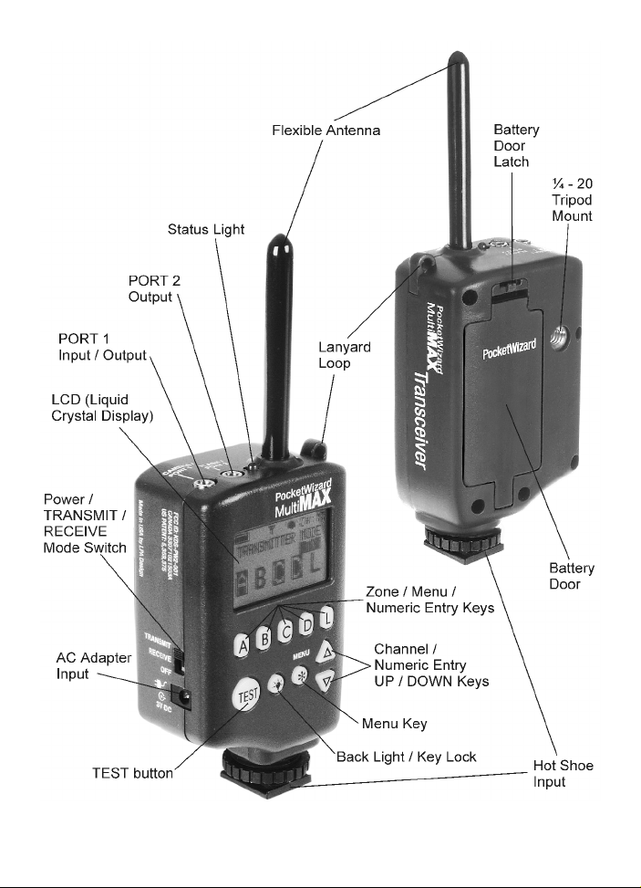
Parts Designation
10
Page 10
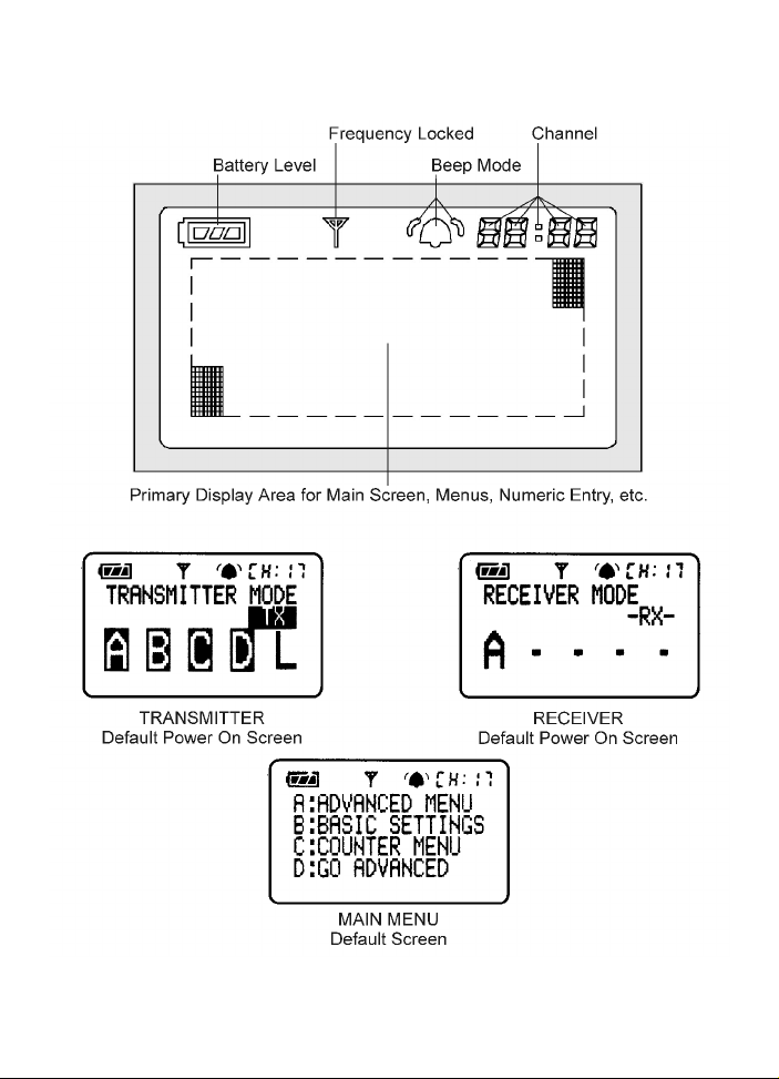
LCD Information
11
Page 11
Controls
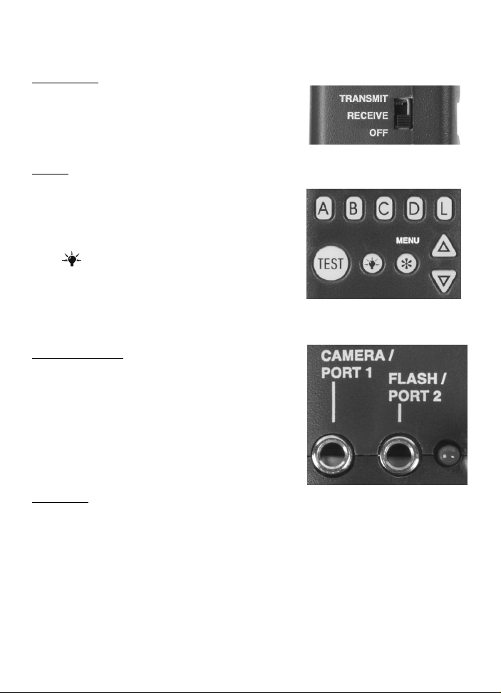
Power Switch
• TRANSMIT Unit is powered on in
• RECEIVE Unit is powered on in
• OFF Unit is powered OFF
Keypad
• A B C D L Selec ts Quad-Triggering Zones
• TEST Triggers MultiMAX. Press to test
• (Back Light) Illuminates LCD and
• ~/MENU Enters or exits menu system.
• (Up / Down) Selec ts chann els.
PORT 1 / PORT 2
• CAMERA / PORT 1 =
• Input from camera sync terminal,
external trigger button, Flash
Confirmation Cable, or other device
• Outpu t to camera motor drive, flash, or
other device
• FLASH / PORT 2 =
• Output to flash, camera motor d rive, or
other device
Status LED
Displays the following information:
• Blinking every few seconds = pow er on, ready for trigger
• Blinking in sync with trigger = normal triggering
• Steady =
• continuously triggered from radio, hot shoe, or PORT 1
• performing delay or contact time
• Slow blink every sec ond = performing Intervalometer or Multi-pop func tion
• Dar k = power off or poor battery condition
TRANS MITTER (T X) mode
RECEIVER (RX) mode
and Local. Also used in menu
navigation and numeric entry
operation or to trigger rem ote units
and/or attached cameras /flashes
keypad. Hold down for key lock
Stores numbers in numeric entry
Also used in numeric entry
Power Switch
Keypad
PORT 1 / PORT 2 / Status LED
12
Page 12

Getting Started
Battery Information
The MultiMAX requires two AA size (IEC: LR6)
batteries. The MultiMA X will operate norm ally with
Nickel Metal Hydride (N iMH), Lithium Ion (Li), Nickel
Cadium (NiCad) and A lkaline batteries.
Alkaline batteries are recommended.
Inserting B atteries
1. Set power s witch to OFF position
2. Open b attery door
3. Insert fres h batteries noting correct orien tation
as displayed in battery compartment
4. Close battery door
5. Use u nit normally
N Erratic unit beh avior or malfunction may occ ur if
batteries are inserted while the power s witch is set to
either RECEIVE or TRANSMIT . Always make sure
the power sw itch is set to OFF before changing or
inserting batteries.
Battery Compartment
Battery Life
The MultiMAX displays remaining battery life with a 3 segment battery icon in the
upper left corner of the LCD:
3 segm ents disp layed = batteries are fresh/new
2 segm ents disp layed = batteries are good
1 segm ent displayed = replace batteries soon
0 segments displayed = ins tall fresh/new batteries imm ediately
W ith one set of s tandard A lkaline b atteries the M ultiM AX will oper ate for approximately
150 hours. This time may vary depending on temperature, battery type, and the
quality of batteries us ed. Extensive us e of back light, speaker, or extend ed trigger
contact tim es will cons ume the batteries at a faster rate.
Battery Icon
13
Page 13

The MultiMAX continually regulates the battery power which gives excellent
performan ce through out the life of the batteries. The un it will continue to function
normally until the batteries are nearly exhausted.
N The MultiMAX voltage regulation is very ef ficient. There is only a small benefit
when using Lithium batteries. Lithium batteries are designed for the quick burst high
current draw found in cameras and portable flash devices. Expect only a 10 - 20%
longer battery life (approximate) over Alkaline batteries when using Lithium batteries.
ë Examine batteries frequently to prevent damage from leaking battery acid.
Remove batteries from MultiMAX units in the following circumstances to avoid damage
from leaking:
• If unit will not be used for a period longer than 2 weeks
• Du ring shipping or air travel
• In high heat environments
Lanyard
A lanyard is inc luded for hanging eac h unit convenien tly on a light stand, tripod , belt,
or other location. If desired, attach the included lanyard to the lanyard loop.
®
VELCRO
VELCRO® adhesive hook and loop fasteners are included w ith the MultiMAX to
provide a convenient m eans of mounting the unit in a variety of places.
Attach as desired being careful to not obscu re controls or f unction. Recommended
mounting locations:
Brand Fasteners
• Right side of th e unit
• Lef t side of u nit
• Below 1/4-20 tripod mount
N The battery door is not a recommended mounting location.
14
Page 14

Care and M aintenance
To ensure continued reliability, please follow these guidelines:
• Do not subject units to high mechanical shock (do not drop!)
• Keep u nit dry. D o not immerse in any liquid
• Set power switch to OFF when not in use
• Rem ove used batteries promptly
• Remove batteries for travel or extended storage
• Clean with soft dry c loth
• Operating temperature: above -15/ (5/ F) and below 50/ C (120/ F)
• Storage temp erature without batteries
• above -30/ C (-22/ F)
• below +85/ C (185/F).
:
15
Page 15

Quick Setup - Basic Radio Slave Operation
Basic Setup for Remote Flash
N Turn off all equipment before installing batteries or making connections!
1. Install 2 AA batteries in each MultiMAX
2. Connect camera to first MultiMAX:
a. Slide u nit into camera hot shoe
- or-
b. Use sync cab le (included) to c onnect camera’s P C termin al to
CAMERA / PORT 1
3. Connect flash to second MultiMAX
a. Use flash cable to connect flash unit’s sync terminal to FLASH / PORT 2
4. Turn both MultiMAX un its on
a. Set power switch on MultiMAX attached to camera to TRAN SMIT mode
b. Set power switch on MultiMAX attached to flash to RECEIVE mode
5. Set both MultiMAX units to same channel and Quad-Triggering zone
a. Us e to set channel (default is CH: 17)
b. Us e A B C D L to select Quad-Triggering zones
(default is TRANSMIT = A B C D L, RECEIVE = A
6. Turn camera and flash on
7. Press TEST button on MultiMA X (set for T RA NSMIT mode) and releas e.
Confirm remote flash triggers.
You’re all set! Use the camera norm ally.
16
Page 16

Triggering Multiple Flashes W ith Multiple RE CEIVE Units
Multiple remote flash units may be triggered in sync with each other.
1. Install batteries in each add itional MultiM AX unit
2. Use flash cable to connect eac h additional flash u nit’s sync terminal to
FLASH / PORT 2
3. Set power switch on each additional MultiMAX unit to RECEIVE mode
4. Set all Mu ltiMA X units to sam e channel as T RAN SMIT unit
You’re all set! Use the camera norm ally.
Connecting MultiM AX (set for TRANSM IT mode) to Flash
A flash can be connected to a MultiMAX (set for TRANS MIT mode). It will trigger in sync
with the remote f lash units. T his flash is called the local flash and is usually mounted
on a camera bracket.
1. Use a flash cable to connect the f lash unit’s s ync term inal to FLASH / PO RT 2 of
the MultiMA X (set for TRA NS MIT mode)
2. Use the L key to enable or disable the Local flash
You’re all set! Use the camera norm ally.
L Using a local flash this way protects the camera from high voltages. See the
Specifications section, Page 50, for more information.
17
Page 17

Standard Radio Operation
Transceiver Control
The M ultiMAX operates as either a tran smitter or a receiver. To use the MultiMA X as
a Transmitter (sending device) set the power switch to TRANSMIT. To use the
MultiMAX as a Receiver set the power switch to RECEIVE.
L There is a special mode that enables a MultiMAX to automatically switch fr om
RECEIVE to TR AN SMIT then back to RECEIV E while triggering a remote c amera.
Read the Relay M ode section, Page 40, for more information.
Channels
The M ultiMAX is a 32 channel digital radio slave. Eac h MultiMAX c hannel repres ents
a digital code trans mitted on specific PocketW izard radio frequencies. T his enables
many photogr aphers to work in the sam e area. It also enables a photogr apher to
control multiple remote devices (cameras, flash units, etc).
A MultiMAX (s et for TRANS MIT mode) will trigger any num ber of MultiMAX units (set
for RECEIV E m ode) set to the sam e channel. Units s et to different channels will not
interfere with each other.
From the main sc reen press the keys to change channels.
Som e MultiM AX features are only available on higher channels. Refer t o the table
below f or features / chan nels availability:
Features Channels 1 - 16 Channels 17 - 32
Digital Radio S ignal X X
Delay including Rear Curtain Sync X X
Intervalometer X X
Multipop X X
Relay Mode X X
Selective Quad-Triggering X
Confirmation (Radio and Flash) X
Fast Mode X
SpeedC ycler X
18
Page 18

Comp atibility
MultiMAX channels are compatible with all PocketW izard radio slave products per the
table below:
Digital Radio Model M ultiM AX Com patible Chan nels
PocketW izard 10 C hannel C lass ic 1-10
PocketW izard 16 C hannel C lass ic 1-16
PocketWizard Plus 1-4
PocketWizard MAX 1-16
Sekonic Digital Radio Transm itter
Module RT-32 (L358, L608, L608 CINE)
Sekonic Digital Radio Receiver RR-4 1-4
Sekonic Digital Radio Receiver RR-32 1-16
Calumet R adio Eq uipped T urbo Filter 1-9
The digital radio design of the MultiMAX will enable it to be fully compatible with future
PocketWizard products.
17-32 Quad-Triggering or Fast Mode
1-16
17-32 Quad-Triggering
17-32 Quad-Triggering or Fast Mode
19
Page 19

Selective Quad-Triggering (A B C D keys)
This powerful feature is used to individually control up
to 4 sets of MultiMA X units (s et for RECEIVE m ode)
on the same channel. Each keypad letter, A B C D
refers to an individual zone. Each zone can be
independently selected or deselected from a MultiMAX
(set for TRAN SMIT mode).
Follow the steps below to test Quad-Triggering:
1. Set one MultiMAX to TR ANSMIT mode
2. Set up to 4 MultiMAX units to RECEIVE mode
(same channel as TRA NS MIT unit)
3. Using the A B C D L keys set each RECEIVE
unit to a different zone
TR AN SM IT un it
Channel: 17
Zones: A, B, and L ocal
4. On the T RA NS MIT unit use the A B C D L keys
to select w hich zones w ill trigger. The zon e is
selected when the letter is displayed on the LCD
screen. The zone is deselected w hen a dot
appears where the letter would be displayed.
5. Press the TEST key on the MultiMA X (set for
TRA NS MIT mode) unit to trigger the selected
zones
Any number of MultiMAX units (set for RECEIVE
mode) may be set to the same channel and zone, and
will trigger simultaneously. Selective Quad-Triggering
is only available on channels 17 and higher.
20
REC EIVE unit
Channel: 17, Zone: A
REC EIVE unit
Channel: 17, Zone: B
Page 20

Class ic C hannels
Class ic c hannels are compatible with early
PocketW izard models and the PocketW izard Plus.
Selective Quad -Trigg ering is only available in
channels 17 through 32. In channels 1 through 16 the
display will show CLASSIC CHANNEL and zones A B
C D do not appear. The A key simply toggles the
remote receivers on or off and is displayed on the
main screen as R. It is not possible to toggle both the
remote (A key) and the local flash (L key) off at the
same time when us ing a CLASS IC C HANNEL.
Operation on these channels is identical to the
function of the LOCAL / BOTH / REMOTE switch
found on PocketWizard Plus and Classic Transmitters.
L Key
On any c hannel the L key toggles the local flas h on or off in a MultiMA X (set for
TRANSM IT mode ).
TRA NS MIT unit set to
CLASSIC CH ANNEL 4
Remote and Local selected
L See the Connecting M ultiMAX (set for TRANSM IT mode) to Flash section,
Page 17, for more information.
L The L key toggles Relay Mode when using a M ultiMAX (set for RECEIVE m ode).
See the Relay Mode section, Page 40, for more information.
21
Page 21

True Confirmation
Because the MultiMAX is a tru e transceiver it autom atically confirms triggering. It can
perform this on two levels: it confirms the round trip radio signal and can confirm
actual flash sync with an optional flash confirmation cable. It does this for all QuadTrigg ering zones on every trigger. C onfirmation is indicated visually on th e main
screen and audibly using beep modes.
L For audible confirmation settings see the Beep Menu section, Page 29.
Radio
Radio confirmation is displayed on T RANSMIT units in the A B C D area of the LCD.
An inverted letter shows an error. A normal letter shows confirmation.
During normal operation the display will show selected and active A B C D zones not
inverted. Confirmation will occur on every trigger and only in th e event of an error will
the zone letters invert.
Option al Flash Conf irmation Cable
Using the flash confirmation cable the MultiMAX can confirm flash sync for all four
zones on every trigger.
1. Attach flash confirmation cable to PORT 1 for each MultiMAX (set for RECEIVE
mode)
2. Locate the sens or so that it can on ly see the flas h from the c orrect flash unit
3. Press the TEST button on a MultiMAX (set for TRANSMIT mode) to test flash
confirmation. Correct flash confirmation is displayed on the main screen with a
flash icon to th e right of each z one performing flash confirm ation. In the event of
an error (either no flash was detected or the radio link was incomplete) the zone
letter and the flash icon will invert
A MultiMAX (set for TRANSM IT mode) will look for RECEIVE units and confirm the
radio link after each of these operations:
• Every trigger
• Pow er on or switch from RECEIVE to TR AN SMIT
• Channel change
• Zone change (including L)
• Exiting the menu s ystem
22
Page 22

N Confirmation can only be performed using MultiMAX units on channels 17 and
higher. PocketW izard Plus, Classic, and the original MAX do not perform
confirmation.
N True Confirmation is designed to work with one MultiMAX (set for RECEIVE
mode) per zon e. Multiple RE CE IVE units set to the s ame channel and zone will not
individually confirm and may cause incorrect confirmation errors. If multiple MultiMAX
units (set for RECEIVE mode) on the same channel and zone are a mix of flash and
non-flash confirmation units then accurate flash confirmation will not be reported.
The following table shows how confirmation works in different modes:
MultiMAX Mode Radio and Flash Confirmation
A R EC EIV E unit us ing Selective
Quad-Triggering
A RECEIVE unit set to a Delay mode W ill not provide confirmation
A RECEIVE unit set to FAST MODE Confirm s on zone A only
A RECEIVE u nit set to Intervalometer
or Multipop
Provides normal radio and / or flash
confirm ation
Provides radio confirmation before
the firs t interval only
23
Page 23

Menu System
Navigation
Many fun ctions of the MultiMA X are acc essed throu gh easy-to-navigate menus .
Press ~/MENU to enter the menu system. Menu items are selected by using the
A B C D L keys.
W hile within the menus the ~/MENU key performs two functions:
• If a menu is displayed, pressing ~/MENU return s you to the main s creen
• If a numeric entry is displayed, pressing ~ /MENU stores the displayed numb er
in memory an d proceeds to either the next input screen or the main sc reen
depending on mode
ë In the next chapters many of the heading s will be follow ed by ~/MENU and some
letter combinations . These are quick references for the keys to pres s to get to that
function f ast.
LCD Contrast Adjustment
W hile in any menu, use the keys to adjust the display contrast.
24
Page 24

Numeric Entry
Several menu items require a number or value to be
entered. Numeric entry is performed with A B C D
and keys. The A B C D keys each select and
add 1 to a specific digit as follows:
A – selec ts and add s 1 to the 4th digit from the right
B – selec ts and add s 1 to the 3
C – selects and add s 1 to the 2nd digit from the right
D – selects and add s 1 to the rightmost d igit
Onc e a digit has been selected, use the keys to
adjust the number. Press and hold for fas ter
entry.
Numbers entered in this fashion are saved when the
~/MENU key is pres sed and w ill remain saved even
after power is turned off. If the unit is powered off
while a numeric entry screen is displayed, the
displayed number will not be saved.
rd
digit from the right
L The L key is not us ed for numeric entry. It is
used for Lag Time M easu rement an d is only
available in certain Delay modes. See the s ection
on Lag Time Measurement, Page 44, for more
information.
ë To quickly get to the lowest setting press and
release the A key once (selects the highes t digit)
then press and hold the key.
EXAMPLE 1
Numeric Entry
EXAMPLE 2
Numeric Entry
25
Page 25

Main Menu
From the main screen press ~/MENU to enter the
Main Men u. Press a letter to either proceed to another
menu or perform a function per the list below.
A: Advanced Menu – ~ /MENU A
Press A to enter the Advanced Menu. The Advanced
Menu contains Delay modes ( including R ear Curtain
Sync), Intervalometer, Multipop, and SpeedCycler modes.
B: Basic Settings – ~/MENU B
Press B to enter the Basic Settings menu. It contains Contact time and Beep menu.
C: Counter Menu – ~/MENU C
Press C to enter the Trigger Counter Menu which contains Counter direction, and
other counter functions: Reset / Clear, Disable, and Load.
D: Go Advanced – ~ /MENU D
D: Go Normal – ~/MENU D
Press D to toggle between the last Advanced mode
used and Normal m ode.
This f unction enables a quic k return to stand ard or
normal operation from an advanced function.
The settings of the advanced function are saved.
Main Menu
Go Ad vanced
Main Menu
Go Nor mal
ë Go Normal is a quick way to get to standard radio slave operation after using
advanced functions and menus. Use this function to “turn off” an advanced mode and
use the MultiMAX as a radio slave only.
26
Page 26

Basic Settings
Press ~/MENU B to enter the Basic Settings menu.
Press the corresponding letter for the setting you wish
to adjust.
A: Contact Time – ~/MENU B A
Contact time is the length of time that C AMERA / P ORT 1 or FLASH /PORT 2 outputs
remain contacted. The default Contact Time of 0.12 is enough to trigger most camera
motor drives and flashes. Many photographers will never need to adjust this number.
Basic Settings Menu
N Contac t time is h ow long th e internal switch is held
closed. For exam ple, if the contact time is s et to 3
seconds and a c amera motor drive is attached to a
MultiM AX, when the MultiM AX triggers the cam era it
will hold the contact for 3 seconds. This is identical to
pressing and holding the camera’s trigger button for 3
seconds. The contact time starts as soon as any input
is complete. Input can be from any of the following
sources : TEST button is pressed, hot s hoe is
triggered, or radio trigger is received.
Set Contact Time Screen
N Contact time is N OT the length of tim e a MultiMAX (set for TR ANSMIT mode) will
send a radio triggering signal. Contact time affects PORT 1 and POR T 2 only and
does not affect radio trigger transmission. Pressing and holding TEST on a MultiMAX
(set for TRANSMIT mode) will continuously send the radio trigger signal and hold the
contact on a MultiMAX (set for RECEIVE) as well as the TRANSMIT unit. W hen the
TEST button is released each unit’s contact time will then begin.
N Additional triggers occurring during contact time are ignored. The default contact
time is 0.12 seconds which triggers all cameras and flash units. A shorter contact time
allows for mor e triggers per second but may not trigger some m otor driven cameras
because it’s too fast. The default setting of 0.12 allows for 8 triggers per second. The
maximum of 30 triggers per second can be obtained by setting contact time to 0.01
seconds.
27
Page 27

For trigg ering remote cameras, a longer c ontact time allows for continuous repeatable
motor drive triggering (example: 5 frame burs ts every trigger). It also allows for
controlled bulb exposure.
• Example of Burst Shooting: If a remote camera is c apable of firing 3 f rames
per second in c ontinuous m otor drive, then a con tact time of 1 sec ond will
always result in this remote c amera triggering for 3 exposu res
• Example of Bulb / Shutter Held Open: Set the contact time for the d esired
bulb exposure time and set the camera to bulb or B mode. When triggered the
shutter will remain open for the contact time
For triggering a remote flash c ontact tim e can act as a flash rec ycle lockout.
• Example of Flash Recycle Lockout: To guarantee that a flash cannot be
triggered fas ter then its recycle time, set the contact time to be jus t longer than
the recycle time
L This method of flash recycle lockout does not work with all flash systems as some
will not recycle while the sync contact is held. S ee Recycle Lockout in the
Applications of Advanced Functions section, Page 42, for another recycle lockout
method.
L If you are using Intervalometer or Multipop modes, read these sections, Page 36
and Page 37, for information on these modes and how they interact w ith Contact Time.
28
Page 28

B: Beep Menu – ~/MENU B B
This m enu c ontrols the beep functions of a Mu ltiMAX.
Press the corres ponding letter to set th e desired
function of the built-in speaker.
A: Bee p on All
MultiMA X will beep on all triggering, confirm ation
errors, and zer o counts as indicated below as well as
on any key pressed.
B: Beep on Trigger
Unit w ill beep when triggered b y TEST button, PO RT 1, a Radio Trigger, or th e Hot
Shoe in the following manner:
C: Beep on Zero / Error
The M ultiM AX un it will not beep on norm al triggering. T he MultiMAX will beep only
when the cou nter reaches zero and on confirm ation errors in the followin g manner:
Beep Cha racteris tic Indicates
Double Long Beep Indicates MultiMAX has reached zero count
L A MultiMA X (set for R EC EIVE mode) s et to Beep on Zero / Error
All will indicate a c onfirmation error if the unit is also set to count d own and the c ounter
reaches zero. S ee the Counter section, Page 30, for more information.
– ~/MENU B B A
Beep Menu
– ~/MENU B B B
Beep Cha racteris tic Indicates
Single Sh ort Beep Indicates P roper C onfirmation
Single Long Beep Indicates T rigger E rror
Single Ver y Short Beep W hen any Key is press ed
– ~/MENU B B C
Single Long Beep Indicates Trigger Confirmation error or remote MultiMAX
(unit set for RECEIVE mode) has reached zero count
Single Sh ort Beep Any Key is p ressed except TEST
or set to Beep on
D: Be ep Disable
Turns off all beep functions. Unit will not beep.
– ~/MENU B B
29
Page 29

Counter Menu
Press ~/MENU C enter the Counter Menu. This menu
controls the counter functions of the MultiMAX. The
counter c an show th e total number of triggers. It can
also count up or down f rom a set valu e. Count is
incremen ted on every trigger from any source:
PO RT 1, TEST button, Hot S hoe, or Radio Trigger.
Counter Menu
A: Count Up + R eset
Count is set to COUNT UP (example: 0,1,2,3,...) and
the counter is reset to 0. T he main sc reen will display
COUNT m: 0.
B: Count Down + Res et
Count direction is set to DOW N (example: 1 0,9,8,7,...)
and the counter is reset to the load counter value. The
main s cr een will d isplay CO UNT o: XXXX
(XXXX = load value)
– ~/MENU C A
– ~/MENU C B
TRA NS MIT unit set to
Count Up
ë The count down function could be used to indicate the number of remaining
frames for a remote camera.
30
Page 30

C: Clear / Reset – ~ /MENU C C
Count direction is not c hanged. C ounter is reset to 0 if count direction is s et to up, or
the counter is reset to the load value if count direc tion is set to down. If the c ounter is
disabled, then th is function will enable the c ounter using the last count direction s et.
The Counter is cleared and reset in this fashion when the unit is powered down.
ë Use ~ C C as an easy to remember qu ick key combination for f ast counter res et.
D: D isable
Counter is disabled and is not displayed on the main screen. W hile disabled the
counter does not count.
L: Load
Enables custom setting of the load count value
(desired nu mber to start the count from, whic h is then
loaded into the MultiMAX computer memory). The
default value is 36. M aximu m value fo r the counter is
9999.
Loading a counter value while the counter is enabled
will set the main screen count to that value and
counting will continue in the las t direction set
(UP or DO W N).
– ~/MENU C D
– ~/MENU C L
Load Counter Screen
N The load counter value is shared with the Intervalometer and Multipop
functions. Setting a count in either of these functions also sets the load count value
for normal c ounter operation.
31
Page 31

Advanced Menu
Press ~/MENU A to enter the A dvanced Menu. This
menu contains the advanced functions of the
MultiMAX. Precision timing and sequencing
operations are available in this menu.
L Press ~/MENU D to cancel advanced functions
and return to normal mode. See the section on
D:Go Advanced and D:Go Normal, Page 26..
A: Delay Menu - TRANSMITTER – ~/MENU A A
Enters th e delay menu for MultiMA X units (set for
TRA NS MIT mode).
L Delay menus, with the exception of Rear Curtain,
require num eric entry. See the Numeric Entry section,
Page 25.
ë All delay screens (numeric entry or rear curtain)
are instantly active and triggering can occur w hile
these sc reens are displayed. A value displayed on
these sc reens will be used immediately on trigger.
This is useful for fine tuning a delay or adjusting rear
curtain sync.
L The maximum delay is 6.4 seconds . For longer
delays see the Intervalometer section, Page 36.
A: Remotes + PORT 2
Enters th e numeric entry sc reen. Delays the rem ote
units and PORT 2. Remote units and PO RT 2 will fire
at the same time after the displayed delay. PORT 2
will remain contacted for the set contact time. On the
main display a small letter D will appear over the right
of the large L to show that the Local output (PORT 2)
will be delayed. Pressing L will toggle the Loc al
output (P O RT 2) on and off, but the s mall D will
remain.
– ~/MENU A A A
REC EIVE unit
Advanced Menu
TR AN SM IT un it
Advanced Menu
TR AN SM IT un it
Delay Menu
TR AN SM IT un it
Remotes + PO RT 2 delayed
32
Page 32

B: R emotes Only – ~/MENU A A B
Enters the numeric entry screen. D elays the Radio rem ote units only. PO RT 2 w ill
trigger immediately. Remote units will trigger after the displayed delay. If the contact
time for t he MultiMAX (set for TR AN SMIT mo de) is longer than th e delay, POR T 2 w ill
remain con tacted for the delay time rather than the contact time.
C: R ear Curtain
Enters th e Rear C urtain screen. Us e this mode to
trigger the flash at the end of an exposure rather than
at the beginning . In this mod e both the Rad io remote
trigger and PORT 2 are delayed.
Use the keys to set the rear curtain sync time
equal to the camera’s shutter speed. C ommon rear
curtain sync times are available per the table below:
– ~/MENU A A C
Rear Curt ain
Sync Time
1/1 1 second 0.98 seconds
½ 0.5 seconds 0.49 seconds
¼ 0.25 seconds 0.24 seconds
1/8 0.125 seconds 0.119 seconds
1/15 0.0667 seconds 0.062 seconds
1/30 0.0333 seconds 0.029 seconds
1/60 0.0167 seconds 0.014 seconds
Decimal
Equivalent
Actual Delay
Rear Cu rtain Screen
Used
L For rear curtain sync times other than the ones displayed above, or for fine tuning
rear curtain times for your specific equipment, press ~/MENU to retu rn to the m ain
screen. Press ~/MENU A A A (see the section A:Delay Remotes + PORT 2
Page 32) and adjust the delay number as needed.
,
33
Page 33

A: Delay Menu - RECEIVER – ~/MENU A A
Enters th e delay menu for a MultiMA X (set for
RECEIVE mod e). Each REC EIVE unit can have its
own delay for seq uences or for sync hronization. T o
easily delay all RECEIVE units the same amount, use
the T ransmitter’s delay.
N RECE IVE units set to delay do not perform
confirmation.
A: PORT 1 + PORT 2
Enters the numeric entry screen. POR T 1 and
PO RT 2 are delayed the same am ount and trigger
simultaneously after the set d elay time. Both ports
remain contacted for the set contact time. Triggers
can com e from either the TEST key or a radio trigger
from any Pock etW izard Trans mitter. On th e main
display a small letter D will appear to denote that
PORT 2 will be delayed.
– ~/MENU A A A
REC EIVE unit
Delay Menu
REC EIVE unit
PO RT 1 + PORT 2 delayed
L Pressing L will toggle Relay M ode on and off but PORT 2 will still trigger after the
set delay. See the Relay Mode section, Page 40, for more information.
B: PORT 2
Enters the numeric entry screen. POR T 1 triggers immediately upon pressing TEST
key or Radio Trigger. PORT 1 contact is held for the set delay time. PORT 2 triggers
after the set delay time and contact is held for the set contact tim e.
– ~/MENU A A B
34
Page 34

C: Equalize – ~/MENU A A C
Equalize Mode is a specialized delay mode for synchronizing multiple cameras to one
flash. This mode is designed to work with shutter speeds up to 1/125 on some
cameras, but there are many factors that could affect operation.
L Read the Camera Equalization section, Page 43 , before continuing.
Equalize mode is designed to be used with at least 3 MultiMAX units (set in RECEIVE
mode). Two or more MultiMAX units will be attached to cameras and one MultiMAX
will be attached to a flash unit. A MultiMAX or other PocketWizard TRANSMITTER
will be used to trigger the system.
1. Place a MultiMAX (set to RECEIVE mode) on the camera hot shoe or attach
cable from camera’s PC terminal to PORT 1
2. Attach cable from PORT 2 to camera’s m otor drive. If available, use a
Pre-T rigger cable (more inform ation in the Camera Equalization section).
3. If the Equalize Screen is not displayed th en
press ~ /MENU A A A from the main sc reen to
enter Eq ualize M ode. This enter s the nu meric
entry screen and 0.1500 secon ds are disp layed
4. Press the L key. The camera should trigger and
a lag time (camera triggering delay) will be
measured and displayed. Press L every few
seconds for 5 to 15 exposures until you see the
fastest lag tim e (lowest number dis played) for
the camera
5. Press the ~ /MENU key to return to t he main
screen. A delay value will be displayed. This nu mber is a c alculated number
and will differ fr om the lag time you saw on the previous sc reen
6. Repeat steps 1 through 5 for each camera to be equalized. Use one MultiMAX
(set for R ECEIVE m ode) per c amera.
7. Attach a MultiMA X (set for R EC EIVE mode) to a flas h unit.
8. From the main screen press ~/MENU A A C. When the num eric entry sc reen
appears with 0.1500 displayed, simply press ~/MENU to return to t he main
screen. Do not adjust the number and do NOT press L. The main scr een will
show a delay of 0.1500
9. Press TEST on any PocketW izard T ransmitter to trigg er this equalized system
Equalize Sc reen
35
Page 35

B: Intervalometer (Time Lapse Photography) – ~/MENU A B
Enters th e Intervalometer interval setting screen.
Intervalometer can be used to trigger a flash or a
camera at a set interval (time gap between triggers) f or
a set nu mber of triggers. The interval tim e is set in
one second increments up to 64000 seconds for a
maximum of 9999 triggers.
1. From the main screen press ~/MENU A B to
enter the num eric entry screen
2. Enter the interval or time gap between triggers
3. Press ~/MENU to proceed to the next s creen
4. Enter the count or number of triggers
5. Press ~/MENU to return to the main s creen.
The in terval will be dis played, and the count will
show the number of triggers to be executed.
6. Press TEST or trigger MultiMAX via Radio to
begin intervalometer fu nction
Intervalometer has two modes of operation depending
on which PO RT is used:
• PORT 1 = first trigger takes place AFTER
first interval
• PORT 2 = first trigger takes place BEFORE
first interval
Intervalometer Mode
Set Interval Sc reen
TR AN SM IT un it
120 sec ond Interval
36 trigger Count
N A MultiMAX (set for TRANSMIT mode) does not send interval radio triggers.
The M ultiMAX (set for T RA NSMIT mode) will send out a single radio trigger pulse at
the beginning of the first interval only. It will con tinue to trigger devices attached to its
PO RTs, but it will not sen d a radio trigger for any m ore intervals. For remote interval
operation, use interval mode on a RECEIVE unit. Each MultiMAX (set for RECEIVE
mode) may have a unique interval setting or can be used with equal settings.
Interval an d c ount entry screen s are in stant ly active
The S et Interval and Adjust Counter screen s are instantly active. W hile the Set Interval
screen is displayed a c hange of interval will be imm ediately executed upon trigger
either from the TEST key or Radio trigger. T he count u sed will be the last count s et.
If the Ad just Coun ter scr een is displayed a change of coun t will be im mediately
executed upon trigger using the last interval set.
ë Intervalometer can be interr upted by pres sing and holding the ~/MENU key.
36
Page 36

ë For delays longer than the 6.4 seconds (maximum available in delay modes) use
Intervalometer or Multipop mode. Set the interval to the desired delay. Set the count
to 1. Attach your camera to PO RT 1 and trig ger the MultiM AX . T he camera will
trigger after the set in terval.
N Contact time affects Intervalometer mode. If the contact time is less than one
second then Intervalometer will function normally. If the contact time is longer than 1
second then the set interval increases p er this formu la: Contact Time P LUS Interval
time MINUS 1 second. Example: If the Contact Time is set to 3 seconds and the
Interval is set to 5 seconds, the actual interval will be 7 seconds (3+5-1=7).
L W hen using Intervalometer and Relay Mode togeth er, a MultiMA X (set for
RECEIVE mode) will switch to Transmit mode and send a Radio trigger after the last
interval. See the Relay Mode section, Page 40, for more inform ation
C: Multipop – ~/MENU A C
Enters the Multipop interval setting screen. This mode
is for triggerin g a flash m ultiple times from one trigger.
It can be used during one long exposure to increase
depth of field or for special effect sequencing. The
interval setting is normally used to set a safe flash
recycling tim e, while the count is set to the number of
flashes or “pops” desired.
Multipop is iden tical in function to Intervalometer w ith
one exception: the m ultipop interval range has finer
resolution; from 0.01 to 640.00 seconds in 0.01 (1/100)
second incremen ts. This allows for fin er control when
setting flash recycle time. This m ode can be used for
cameras or flash units.
1. From the main screen press ~/MENU A C to
enter the numeric entry screen
2. Enter the interval or time gap between triggers
3. Press ~/MENU to proceed to the next s creen
4. Enter the count or number of triggers
5. Press ~/MENU to return to the main s creen.
The in terval will be dis played, and the count will
show the n umber of triggers to be executed
6. Press the TEST key or trigger the M ultiMAX via
Radio to begin Multipop function
Multi-pop Mode
Set Interval Sc reen
TR AN SM IT U nit
5.00 sec ond M ulti-pop Interval
10 trigger Count
37
Page 37

The following chart is a starting point for calculating how the number of flashes or pops
affects F-stops. Since every flas h unit is different, us e a light meter or other m ethod
for more precise calculations.
Number of Pops Stops Number of Pops Stops
1 Add 0 stops 6 Add 2.5 stops
2 Add 1 s top 8 Add 3 stops
3 Add 1.5 stops 12 Add 3.5 stops
4 Add 2 stops 16 Add 4 stops
N Contact time is affected b y Multipop m ode. If the contact time is s et greater than
the Multipop inter val, the contact time will automatically be set to interval time MINUS
0.01 sec onds. This m eans that a remote camera or flash will remain tr iggered with
only a 1/100 second release between contacts. This short released time may not be
long enough to re-trigger some cameras or flash units. If this is the case, set the
contact time lower.
D: SpeedCycler - TRANSMITTER – ~/MENU A D
Enables Sp eedCycler mode. Use th is m ode to rapid ly
cycle throug h remote flash units and trigger fas ter than
a single flash can recyc le by using multiple flash units.
It can also be used for triggering remote c ameras
sequ entially.
This mode only works with Q uad Triggering ch annels
(17 and higher) and two or more MAX or MultiMAX
units (set for RECE IVE mode).
1. From the main screen press ~/MENU A D to
enable SpeedC ycler m ode on a MultiMA X (set for TRA NSMIT mode)
2. Enable two or m ore remote zones
3. Set each MultiMAX (set for RECEIVE m ode) to a different zone
4. Trigger the MultiMAX (set for TRANSMIT mode). The first trigger will fire the
first zone selected, the second trigger will fire the next zone selected. The
display indicates the next zone to trigger with an arrow. Only the zone just
triggered will display proper confirmation
TR AN SM IT un it
SpeedCycler Mode
A = triggered with flash
confirm ation
B = next zone to be trig gered
N If L is selected then P ORT 2 on the M ultiMAX (set for TRAN SM IT mode) w ill
trigger every time and is not cycled. It will be in sync with each cyc led zone.
38
Page 38

D: Fast Mode - RECEIVER – ~ /MENU A D
The MultiMAX is designed to sync cameras and flash
units at shu tters s peeds up to 1 /250th for most f ocal
plane shutters (35m m) and 1/500th for most leaf
shutters. Some camera and flash combinations are
capable of fast sync speeds up to 1/1000th. The
MultiMA X (set for REC EIV E mode) is capable of
operation at these speeds in Fast M ode. Check your
camera’s and flash unit’s manuals for the maximum
sync speeds allowed by your equipm ent.
A MultiMAX (set for RECEIVE mode) in fast mode will show FAST M ODE on the
display. While in this mode Quad-Triggering and Relay Mode are not available and
the A B C D L keys perform no func tion on a REC EIV E unit. A M ultiMAX (set for
TRANS MIT mode) will trigger RECEIVE units in FAST MO DE with any remote zone
selected, bu t will perform confirm ation only on zone A .
REC EIVE unit
Fast Mode
Other Features
Keypad Lock – Hold
This f unction prevents inadvertent key p resses. Press and hold the key for 3
seconds to toggle keypad lock on or off.
All keys are locked except and TEST.
W hile the keypad is locked pres sing any of the keys , A B C D L or ~/MENU will
display the message “KEYP AD LOCK ED .”
High Voltage Protection
Many electronic cameras can be damaged by high flash sync voltage. Refer to your
camera’s manual for more information. The MultiMAX protects the camera from high
flash sync voltage. The MultiMAX can accept up to 250 volts, but there is only a safe
3.3 volts present at the hot shoe or PORT 1. A cam era triggering a M ultiMAX (set for
TRANS MIT mode) via the hot shoe or POR T 1 only encounters 3.3 volts. This voltage
is not MultiMAX battery dep endent and will not vary over the life of the batteries.
L See the Hot shoe notes in the Specifications sec tion, Page 50 an d Page 51, for
more inform ation
39
Page 39

Relay Mode (RECEIVE Mode Only) – L
In this m ode a remote camera’s motor drive is
triggered by a MultiMAX (set for RECEIVE mode). The
MultiMAX then switches to TRAN SMIT mode and
waits for a sync pulse from the camera. Upon getting
the sync pulse from the camera the unit then triggers
remote flash units via radio and returns to RECEIVE
mode, r eady to trigger the camera again. Usin g this
mode it is possible, using only 3 PocketWizard units,
to have complete wireless triggering.
1. Set a MultiMAX to TRANSMIT m ode and select the channel and zones for the
remote flash u nits
2. Set the sam e MultiMAX to RECEIVE m ode and select the channel and zone for
the remote camera. Use a different channel then the remote flash units.
3. Press L to togg le Relay Mod e on. T he scr een will display RL Y XX (where XX is
the T RANSMIT ch annel to be us ed f or relay)
4. Connect the camera’s PC terminal to PORT 1 or attach the MultiMAX to the
camera’s hot shoe
5. Connect the camera’s motor drive to PORT 2
6. Trigger the MultiMAX via radio trigger. The camera’s motor drive will trigger and
the MultiMAX display will change to TRAN SM IT mode. T he MultiMAX will wait
1.5 sec onds for a trig ger from the c amera. If it gets a trigger in th at time it will
trigger the remote f lash units and return to REC EIVE mode. If it does not get a
trigger in that time it w ill return to REC EIV E mode without triggerin g the remote
units.
Software Version Display – Hold A on power up
To check the software version of the MultiMAX without resetting the unit to factory
defaults, perform the following
RECEIVE unit in Relay Mode
Receives Channel 22, Zone A
Transmits Channel 20
1. Set power switch to OFF
2. Press and hold A key
3. Continue to hold A and s et the power switch to either R EC EIVE or TRA NSMIT
4. Release A key when software version appears
5. Use u nit normally
L See the Reset to Default Factory Settings section, Page 53, for more
information.
40
Page 40

Applications of Advanced Functions
The applications below are unique ways to use the advanced functions of the
MultiMAX. Many of them require fine-tuning or adjustment to work with different
camera equipment. Always perform test exposu res to insure reliable results.
Self-Timer or Cable Release
Delays, or Intervalometer and Multipop with a count of 1, can be used as a camera
timer for self portraits or as a trigger delay to reduce camera shake. Review Delay,
Intervalometer and M ultipop sections for more information.
TTL / Auto flash Helper
W hen using an on-camera TTL flash or Automatic exposure flash with a remote flash
there may be situations where you do not want the rem ote flash to affect the TTL or
Auto flash sensor. The on-camera flash can underexpose by quenching early (turning
off too so on) because it m easu red the light from the remote flash. T he reverse of this
can also be u ndesirable. If the remote flash is in Automatic mode, it may quenc h too
early because it sensed the light from the on camera flash.
Using Delay mode c an help solve this problem. F ollow the steps b elow if using a TT L
or Automatic flash attached directly to the camera:
1. Attach the camera’s PC terminal to PO RT 1 on a MultiMA X (s et for TRA NSMIT
mode)
2. Attach manual or Automatic flas h to MultiMA X (set for REC EIV E mode)
3. On the MultiMAX (set for TRANSMIT mode) press ~/MENU A A B to enter the
set delay scr een
4. Enter in a delay of 0.0020 (1/500)
5. Trigg er the camera nor mally
The on -camera flas h will trigg er imm ediately and h ave enough time to com plete its full
exposure. After the set delay time the remote flas h will trigg er. This operation is
dependent on camera sync speed and flash duration. The delay time of 0.0020
(1/500) will work with a focal plane shutter (35mm camera) at 1/125 shutter speed and
a flash duration not longer than 1/400.
41
Page 41

Use the formula below to help calculate your m aximum safe shutter speed b ased on
your flash durations.
L Refer to the Tim e Conv ersion Charts section, Page 55, to c onvert fractions in to
decimals for the formu la.
1. Add your maximum (longest) flash durations together (decimals, not fractions)
2. Add anoth er 0.002 (focal plane) or 0.00 1 (leaf shutter) to com pensate for shutter
travel time
3. On the Shutter Speed Conversion chart find the next highest decimal number
in the chart. T he corresponding shutter s peed is the fastest speed you can
safely use for this procedure
4. Set the delay time on the MultiMAX (set for TRANSMIT mode) to the same
number as your on-c amera flash u nit’s longest flash duration
Programmed sequence shooting
Traveling str oboscop ic effects can be achieved by using multiple Mu ltiMAX units (set
for RECEIVE mode) in delay mode. Set each RECE IVE unit to a different delay and
trigger from a P ocketW izard. The sequence is identical on repeat triggers.
Recycle Lockout
Some flash units can be damaged if they are triggered too quickly or before they are
fully recharged. This may cause the flash to overheat. Use Multipop Mode to protect
the flash by setting a safe recycle lockout time. Follow the steps below:
1. On a MultiMAX (set for RECEIVE mode) press ~/MENU A C
2. Enter the desired recycle lockout time and press ~/MENU
3. Enter a count of 1 and press ~/MENU
4. Attach remote flash to PORT 2
Example: If the loc kout time you entered was 3 secon ds, then the rem ote flas h could
not be triggered more than once every 3 seconds.
42
Page 42

Camera Equalization
Equalization, or syn chronizing multiple cameras to the same flash , requires precision
timing. Even th ough we perceive camera triggering activity as ins tantaneous, it is not.
Even the flash , which appears to provide light only for an instan t, has a time duration
(flash duration) that needs to be factored into synchronization calculations.
Every camera h as a delay from the time it is triggered until the shutter is fully open.
The trigger can originate from either the c amera’s trig ger bu tton or via the m otor drive
port. This delay is called lag time and it can be different from camera to camera and
may even vary between two cameras of the exact same model. If two cameras are
triggered at exactly the sam e time their s hutters will be open at different moments . If
one camera is attached to a flas h, the other cam era’s shutter will probably not be op en
at the right moment to capture the flash.
Some cameras are not suitable for equalization. For best equalization a camera must
have a consis tent lag time. If a cam era’s lag tim e varies widely or unpredic tably from
shot to shot th en it may not be pos sible to synchronize that c amera. This is not a flaw
of either the camera or the Mu ltiMAX. A varying lag time in a cam era is considered
acceptable operation for the majority of p hotograph ic situations. C ameras are us ually
designed to res pond p redictably shot to s hot, but are not necessar ily or specifically
designed to do so with the precision needed for equalization. Many factors can affect
a camera’s lag time:
• Camera Pre-Trigger status
pres s “wakes up” th e cam era, full pres s triggers the c amera) will p robably h ave
widely different lag tim es if triggered while awake versus asleep. C ameras
usually have more c onsistent lag times if th ey are kept “awake” or Pr eTriggered. The camera will also respond more quickly, but will consume
batteries at a faster rate. Pre-Trigger cables are available from PocketW izard
for many cameras
• Cam era batteries
batteries fade, especially in primarily mechanical cameras. Fresh batteries are
recommended f or equalization
• T emperature and humidity
camera may move differently thus affecting lag time. A temperature increase
may decrease lag time as the c amera’s internal lubricants are warmed and flow
more freely or vice versa
• Horizontal vs vertical orientation
orientations various mech anism s, especially sh utters in focal plane cam eras, will
be affected b y gravity making them move differently thus affecting lag tim e. In
general, do not ch ange a camera’s orientation during equalization
– lag times may begin to drif t or slow down as the cam era’s
– cam eras that have a two s tage trigge r button ( half
– as these factors change, the mechanical parts of a
– as a camera is moved through these
43
Page 43

• Multiple mechanical systems – cameras that have ma ny chan geable
mech anically interacting parts (film bac ks, motor drives, lens shutters) are likely
to have different lag tim es with diff erent hardware comb inations. A leaf shutter
is in the lens s o changing lenses on a leaf shutter c amera will change lag time.
In some m edium format cam eras having the film bac k loaded versus unloaded
can make a significant difference. For consistent results always use the same
components (lens, body, and film back combination for example) each time
• Auto-focus and exposure computers
will introduce widely varying lag times as lens travel and exposure calculations
can take unp redictable amou nts of time. An electron ic camera s et to full manual
generally provides the m ost consistent lag tim es
Lag Time Measurement
~/MENU A A A L or ~/MENU A A B L or
~/MENU A A C L (RECEIVE units only)
The firs t step to c amera synchronization or equalization is measu ring a camera’s lag
time (triggering delay). The MultiMAX can measure a cam era’s lag time in most delay
modes. K nowing your camera’s lag time is critic al for camera equalization, but can
also be usef ul in spec ial effects, industrial, com merc ial, or other photography th at
requires critical trigger timing.
Using the inform ation above set up your c amera for best equalization performance.
Attach a MultiMAX (set for RECEIVE mode) to the camera as follows:
1. Place a MultiM AX in th e cam era’s hot s hoe or attach a cable from the cam era’s
PC terminal to PORT 1
2. Attach the cable from PORT 2 to the camera’s motor drive. If available, use a
Pre-R elease c able
3. Press ~/MENU A A A for a standard delay mode where lag times can be
measured
4. The screen should display “Set Delay Using A B C D L “ and show a
numeric value. Press L. The unit w ill trigger the cam era and time the delay until
a sync pulse is sensed from the hot shoe or lens
5. Press L every few seconds to find the fastest and slowest lag times for the
camera. Usually the first press of L will yield a very different number from later
measurements. Ignore the first reading. 5 to 15 lag time measu rements af ter
the first one should yield consistent results and give a gauge of the fastest and
slowest times
6. Using steps 1 through 5 , measure and record the fastest and slowes t lag times
for each camera you wish to equalize. Subtract the fastest from the slowest and
record this number as the cam era’s lag time variation
–
– some auto-focus and exposure systems
44
Page 44

ë Speed is not the most important factor in camera equalization, consistency is. If a
slow camera has extrem ely consistent lag tim es it will be a better equalization
candidate than a faster but inc onsistent camera. T he reas on why it is imp ortant to
know the approxim ate fastest lag tim e for a camera, es pecially an inc ons istent one, is
to calculate margin of error (discussed later in this section).
The am ount of drift or lag tim e inconsistenc y determines th e highest shutter speed at
which a camera will reliably equalize. The following table should be used as a starting
point for testing purposes only. The numbers in this table are based on a 1/1000th or
faster flash duration.
Shutter S peed Probable maximum safe
lag time variation for
average focal plane
(35mm) camera
1/300 <=0.0003 <=0.0013
1/250 <=0.0010 <=0.0020
1/200 <=0.0020 <=0.0030
1/180 <=0.0025 <=0.0035
1/125 <=0.0050 <=0.0060
1/90 <=0.0080 <=0.0090
1/60 <=0.0137 <=0.0147
1/30 <=0.0303 <=0.0313
1/15 <=0.0637 <=0.0647
1/8 <=0.1220 <=0.1230
1/4 <=0.2470 <=0.2480
1/2 <=0.4970 <=0.4980
1 <=0.9970 <=0.9980
2 <=1.9970 <=1.9980
Probable maximum safe
lag time variation for
average leaf shutter
camera, F:8.0
N Leaf shutters have different s hutter blade travel times depending on aperture. A
wider aperture takes longer and reduces th e amount of varianc e allowed. A s maller
aperture takes les s time thereby increasing the allowable variance. (A leaf s hutter set
to F:4.0, for example, may reduce the variance to the same as a focal plane camera).
45
Page 45

N If your camera’s maximum sync speed is slower than the numb er listed then you
must u se the slower s ync s peed. Camera equalization does not give a camera faster
sync speeds than the cam era is designed to handle.
For all shutters it can be assumed that a camera with faster external flash sync speeds
(X sync) will have faster sh utter travel than cameras with s lower X sync speeds .
Faster sh utter travel times increase the allowable variance. The table above is b ased
on the following shutter travel times:
• Focal Plane (35mm) – 1/1000 (0.0010) to open, 1/1000 to close
• Leaf shutter at f: 8.0 – 1/2000 (0.0005) to open, 1/2000 to close
If a flash is generating light while th e shutter is moving then you will see the s hutter in
the exposure for focal plane shutters. You will see a loss in F stop exposure using a
leaf shutter if the flash is generating light as the shutter aperture opens or closes.
A variable flash duration will also affect these calc ulations. A slow flash is visible for
longer and more likely to affect exposure while the shutter is in motion. A short flash
duration reduc es the likelihood of timing variances affecting the exposure.
It is difficult to measu re a shu tter’s travel tim e or a flas h units duration an d it usually
requires extremely expensive test equipment. Some electronic flash manufacturers
print their flash durations in their manual. The best method for understanding your
equipment’s equalization cap abilities is to shoot m any test exposures over a range of
settings.
Recommend E quipment for the best results
• Con sistent lag tim e cameras
• Cameras with ast sync speeds
• Electronic flash equipment with short flas h duration
46
Page 46

One U nit Equalization
To equalize two cameras and one flash at 1/125 with one MultiMAX, follow these
steps:
1. Set the MultiMAX to REC EIVE mode
2. Measure lag times of cameras as described and record the fastest lag for each
3. Determ ine which c amera is faster and which is slower overall
4. Determine the delay time
a. If the s low cam era is more con sistent use this formula:
i. Slower Camera’s Fas test Lag Time MIN US Faste r Cam era’s
b. If the fast c amera is more cons istent use th is formu la:
5. Press ~/MENU A A B then enter the calculated delay time from Step 4
6. Attach the slower camera’s motor drive to PORT 1
7. Attach the faster camera’s motor drive to PORT 2
8. Attach the flash to the more consistent (smallest lag time variance) camera
9. Trigger th e RECEIVE unit either f rom the TEST key or f rom a T RANSM IT unit
Two U nit Equalization
Two U nit Equalization is basically the same as above, bu t allows the two cam eras to
be m ore rem ote. T he differen ce in c alculations compensates for rad io trigger delay.
1. Set one MultiMAX to REC EIVE mode, and one to TR ANSMIT mode
2. Using the RECEIV E unit, measure the lag times of each camera as described
above and record the fastest lag for each
3. Determ ine which c amera is faster and which is slower overall
4. Determine the delay time
1. If the slow camera is m ore consis tent use this formu la:
2. If the fast c amera is more cons istent use th is formu la:
5. On the RECEIVE unit press ~/MENU A A A. Enter the time from Step 4
6. Attach the slower camera’s motor d rive to PORT 2 on the TRA NSMIT unit. Do
not leave the MultiMAX (set for TRANSMIT m ode) in the hot shoe or have the
PC terminal attached to PORT 1 as this m ay cause a looping or loc k-up situation
7. Attach the faster camera’s motor drive to either PORT on the REC EIVE unit
8. Attach the flash to the more consistent (smallest lag time variance) camera
9. Trigger the system from the TRANSMIT unit’s TEST key
Fastest Lag Time MINUS 0.0025 {calculated safety margin}
i. Slower Camera’s Fas test Lag Time MIN US Faste r Cam era’s
Fastest Lag Time PLUS 0.0025 {calculated safety margin}
1. Slower Camera’s Fas test Lag Time MIN US Faste r Cam era’s
Fastest Lag Time MINUS 0.0030 {calculated safety margin}
1. Slower Camera’s Fas test Lag Time MIN US Faste r Cam era’s
Fastest Lag Time PLUS 0.0020 {calculated safety margin}
47
Page 47

If using both MultiMAX units as R ECEIVE units being triggered by any PocketWizard
Transmitter follow these steps:
1. Set both units to REC EIVE mode
2. Measure lag times of cameras as previously described and record the fastest
lag for each
3. Determ ine which c amera is faster and which is slower overall
4. Determine the delay time
a. If the s low cam era is more con sistent use this formula:
i. Slower Camera’s Fas test Lag Time MIN US Faste r Cam era’s
b. If the fast c amera is more cons istent use th is formu la:
5. Attach the slower camera’s motor drive to either PO RT on the first un it
6. Attach the faster camera’s motor drive to either PORT on the second unit
7. On the second unit press ~/MENU A A A, then enter the calculated delay time
from Step 4
8. Make s ure there is no delay being perf ormed on the first unit
9. Attach the flash to the more consistent (smallest lag time variance) camera
10. Trigger the system from a TRANSMIT unit’s TEST key
Fastest Lag Time MINUS 0.0025 {calculated safety margin}
i. Slower Camera’s Fas test Lag Time MIN US Faste r Cam era’s
Fastest Lag Time PLUS 0.0025 {calculated safety margin}
L If using 4 or more units you may find it easier to use the built-in E qualize m ode.
See the Equalize section, Page 35, for more information.
48
Page 48

Equalization A djustments
W ith all the variable factors above it may seem that performing the math nec ess ary for
equalization is daunting. Here are some techniques for fine- tuning or adjusting
equalization times without using specific math:
On some 35m m cameras you can gauge timing without using film. If your camera
allows t rigger ing with the film back open you can ver ify synchronization visu ally.
1. Perform the steps above to get basic equ alization started
2. Point the flash at a blank wa ll
3. On the camera NOT attached to the flash, set the shutter speed to 1/60
4. Open that camera’s back
5. Point the camera at the same wall as the flash
6. As the camera and flash are being triggered look through the shutter plane
through the lens at the light from the flash hitting the wall. CAUTION: MAKE
SURE the flash is set to a comfortable level for your eyes!
7. Note the s hape of the light burst. If it is a perf ect b right cir cle then the cam era is
in sync. If the circle is dark or has a hard line running along one edge then the
camera is not in sync. T he hard line is th e shutter in m otion while th e flash is
still generating light
8. Adjust the s hutter s peed up or down until you s ee a perfec t circle
ë The delay time setting screen is instantly active. W hile in numeric entry mode
you can adjust the delay up or down and the displayed value will be executed on the
next trigger. Using the “through-the-back” method above or by shooting film, Polaroid,
or digital you c an adjust the d elay and view the results to more s uit your specif ic
camera’s timings.
The mathematical formulas used thus far are designed for equalizing at 1/125. The
final offset n umber (0.0025 for example) may need to be adjusted when attemp ting to
equalize at faster shutter speeds or slower ones with wide lag variation cameras. The
offset number tries to move the flash b urst to the middle of the exposure to
compensate for drifting lag time. Experiment with different offsets to fine tune your
shutter s peed, flash d uration, and camera timing combinations. T oo long or short of
an offset an d you limit a c amera’s ability to get the exposu re if the lag d rifts , even by a
small amount.
ë Visit http://www.pocketwizard.com/
equalization techniq ues. As more information becomes available it will be posted
there.
for more inform ation on camera s pecific
49
Page 49

Technical Information
Specifications
W eight: 5.4 ounces w ith alkaline batteries
Dimensions: 1.4 inches deep x 2.1 inches wide x 4.0 inches tall (body only)
Batteries: 2 x AA (IEC:LR 6), 1.5 V batteries, alkaline recommended
AC Adapter Jack: 3 VDC unregulated, 0.3 A (3 00 m illiamp) or higher
Input / Output Ports:
Size 3.5mm (1/8") mono miniphone
Maximum Input Voltage 250 VDC
PORT 1 current handling 0.5 A (½ Amp), current limited
PORT 2 current handling 4.0 A for 0.00002 seconds (1/50000 second
PO RT 1 polarity tip positive, n on-revers ible
PO RT 2 polarity tip positive, reversible
PO RT 1 and Hot S hoe
Voltage present
PO RT 1 and Hot S hoe
triggering thres hold
PO RT 1 and Hot S hoe
holding current
Flexible antenna = 2.4 inches tall. 0.3 inches in diameter
Read the Getting Started section, Page 13, f or more inform ation
4.5 VDC regulated, 0.2 A (200 milliamp ) or higher, (recommen ded
Polarit y = center positive, ou tside n egative
Male plug specifications: 1.3mm ID, 3.4mm OD, 1cm long
or 20 microseconds)
0.25 A (1/4 Amp or 250 milliamp) continuous,
current lim ited
3.3 VDC, 0.001 A (1/1000 Amp or 1 milliamp),
regulated
< 2.2 V
0.0005 A (1/2000 Amp or 50 microamps)
)
HOT SHOE NOT E #1: PO RT 1 and the hot s hoe are electrically connected together .
A device attached to PORT 1 will trigger when the TRANSMIT unit is triggered by the
hot shoe. T his is not controllable by the L key. While the device may trigger in sync
with the shutter, it will not be controlled by the MultiMAX. If the device is a high
voltage flash unit then the MultiMAX does not provide voltage protection to the camera
in this situation. For normal operation do not use PORT 1 to trigger a high voltage
flash on a T RA NSMIT unit unless nothing is attach ed to the hot s hoe.
50
Page 50

HOT SHOE NOT E #2: Some cameras may exhibit undesirable behavior if the
RECEIVE unit is mounted in th e camera hot shoe when that camera is being fired
remotely. Some cameras’ hot shoe and motor drive contacts may share some
connections. This can cause the camera to lock up or stop operating normally. If your
camera does not function properly in this mode then remove the unit from the
camera’s hot shoe.
Radio Information
• Trans mit O utput Pow er: 0.001 watt (1/1000 of a watt or 1 m illiwatt)
• Typical Transmitter Output Duration: 0.0005 seconds (1/2000 second or 50
microseconds)
• Bandwidth: Narrowband, 70KHz TRANSMIT, 230KHz RECEIVE
PocketWizard Radio Frequencies:
Channel Frequency Unit Digital Code
1 through 16 344.04 MHz Classic, Plus,
17 346.50 MHz
18 347.00 MHz
19 347.50 MHz
20 348.00 MHz
21 348.50 MHz
22 349.00 MHz
23 349.50 MHz
24 350.00 MHz
25 350.50 MHz
26 351.00 MHz
27 351.50 MHz
28 352.00 MHz
29 352.50 MHz
30 353.00 MHz
31 353.50 MHz
32 354.00 MHz
MAX, and
MultiMAX
MultiMAX and
MAX only
16 Bit
24 Bit
(20 Bit in
FAST MODE)
51
Page 51

Maximum and Minimum Settings
The following table details the maximum and minimum values allowed for each
numeric entry setting available in the MultiMAX.
Setting M aximum Minimum
Contact Time 640.00 s econds or
Delay Time 6.4000 seconds .0001 seconds
Interval (Intervalometer
mode)
Interval (Multipop mode) 640 .00 seconds or
Count (for Load Count or
Intervalometer / Multipop)
Intervalometer maximum time is 64000 second intervals for 9999 triggers or 177,760
hours (7,406 days, 16 hours) or approximately 20 years, 3 months, 11 and 2/3 days.
Saved Settings
Settings are s aved whenever the ~/MENU key is pressed. The following settings are
always RESET on normal power down:
• Counter (resets to saved load value if count is o, resets to 0 if count is m)
• Rear Curtain Sync (fraction display returns to 1/1)
• Any dynamic num eric entry s creen disp layed as un it is power ed off will default
to its previous saved setting. T he screen s affec ted are : Load counter, Delay
time, and Interval (Multipop or Intervalometer)
10 minutes, 40 seconds
64000 s econds or
17 hours, 46 minutes,
40 seconds
10 minutes, 40 seconds
9999 0
.01 seconds
(add 0.0005 to displayed
value for RECEIV E units
triggered via radio)
1 second
.01 seconds
The following settings are saved on power down:
Channel Beep Mode Delay Time
Zone Contact Time Interval
Relay Mode Load Count Advanced Mode
Fast Mode Counter Mode
52
Page 52

Troubleshooting
When in doubt !
Many issues can be resolved by powering the unit off and then back on again or by
resetting to factory default settings. Before proceeding to any other troubleshooting
procedure follow these steps:
1. Set power to OFF
2. W ait 10 seconds or until display completely blanks
3. Set power to R EC EIVE or TRA NSMIT
Reset to Default Factory Settings
1. Set power switch to OFF
2. Press and hold C key
3. Continue to hold C and s et the power switch to either R EC EIVE or TRA NS MIT
4. Release C key when CLEA R/RES ET message appears
Default factory settings are as follows:
Channel 17 Display Contrast Medium
Trans mitter
Zones
Receiver Zone A Equalize
Relay Mode OFF Interval Time 100 sec
Operating mode NORMAL Multipop Time 1.00 sec
Contact Time 0.12 sec Counter Mode OFF
Beep Mode All Counter Load 36
Fast Mode OFF
A B C D L all
enabled
Delay Time 0.0100 s ec
0.1500 s ec
Calculated Time
N The following indic ators may operate erratically during res et, but will return to
normal operation when reset completes: B attery Level, Frequenc y Lock, Beep Mode,
and C hannel.
L The CLEAR/RES ET message also displays the software version installed in the
unit. To view just the software version without losing settings refer to the Software
Version Display section, Page 40, for more information.
53
Page 53

Radio Performance
The MultiMAX is an advanced digital radio system. Its true digital technology
guarantees optimum interference rejection while maintaining high performance. As
with all radio devices (cell phones, walkie talkies, cordless sound systems) there are
some situations wher e performance may be degraded by outs ide factors. F or
maximum radio performance for the MultiMAX, or any radio device, follow the
guidelines below:
• Keep an tennas parallel. T he antenn a radiation and reception pattern is
designed for best performance in this orientation.
• W hile not required for operation, main taining line of sigh t between T RA NSMIT
and RECEIVE units will give best performance. Radio can work through objects,
but its range may be reduced.
• Mount REC EIV E units aw ay from metal objec ts. Some metal objects can act as
an antenna. T he radio noise in an area may be conducted by the m etal and can
reduce the range of a RECEIVE u nit which w orks harder to reject extra noise.
Moving a R ECEIVE unit a few inches away from metal, or m ounting the unit
such that the antenna is away from or above the metal, will eliminate this issue.
• Mount units away from water. Water absorbs radio energy. If shooting around
water-filled objects try to maintain line of sigh t between units when ever possible.
Sources of water that might affec t a unit’s range are:
• T rees – if sh ooting in a large forest w ith many trees, try to maintain line of
sight
• People – mount RECEIVE units above the heads of large crowds and use
TR AN SM IT un its in the c amera’s hot s hoe when ever possible
• Rain – Heavy downpours may affect range
• Large metal and concrete structures affect radio. Attempting to trigger through
large metal or conc rete objects or buildings will result in a reduc tion in range.
Try to mount RECEIVE units in windows for best performance when shooting
architecture.
• Flas h pack mounting – mount the RECEIVE unit with the antenn a com pletely
above the top of the body of the flash unit. Keep the antenna away from the
metal in a f lash un it
If you are experiencing range problems and you h ave followed the guidelines above,
try moving the R EC EIVE unit a few inches in any direction. Radio reflec tions from
surrounding objects can sometimes cause nodes, or “dead spots.” Relocating the
RECEIVE unit jus t a few inches from these sp ots can dram atically improve range.
ë Visit http://www.pocketwizard.com/
information becomes available it will be posted there. Be sure to check out the
Frequently A sked Questions section on the website.
for more troubleshooting information. As more
54
Page 54

Time Conversion Charts
Fractions to Decim al
Here are some common photographic fractions in decimal values. All numbers are
rounded to the nearest .0001 or 1/10,000th.
:
L These times are not Rear Curtain S ync times. Thes e are precision n umbers .
Rear Curtain Sync numbers are always less than the exact conversions. Refer to the
Rear Curt ain section, Page 33, for more information.
Fraction Decimal Fraction Decimal
½ 0.5 seconds 1/180 0.0056 seconds
1/4 0.25 seconds 1/200 0.005 seconds
1/8 0.125 seconds 1/250 0.004 seconds
1/15 0.0667 seconds 1/500 0.002 seconds
1/30 0.0333 seconds 1/1000 0.001 seconds
1/60 0.0167 seconds 1/2000 0.0005 seconds
1/90 0.0111 seconds 1/4000 0.0003 seconds
1/125 0.008 seconds 1/8000 0.0001 seconds
Seconds to Minutes and Hours
Use the following table to help calculate long intervals or delays.
Seconds M inutes Seconds Hours
60 seconds 1 minute 3600 seconds 1 hour
120 seconds 2 minutes 7200 seconds 2 hours
180 seconds 3 minutes 10800 seconds 3 hours
240 seconds 4 minutes 14400 seconds 4 hours
300 seconds 5 minutes 18000 seconds 5 hours
600 seconds 10 minutes 36000 seconds 10 hours
1200 seconds 20 minutes
1800 seconds 30 minutes
:
55
Page 55

Manual Revision 1.10 (LP521)
 Loading...