

Page 1
Quick Start Guide
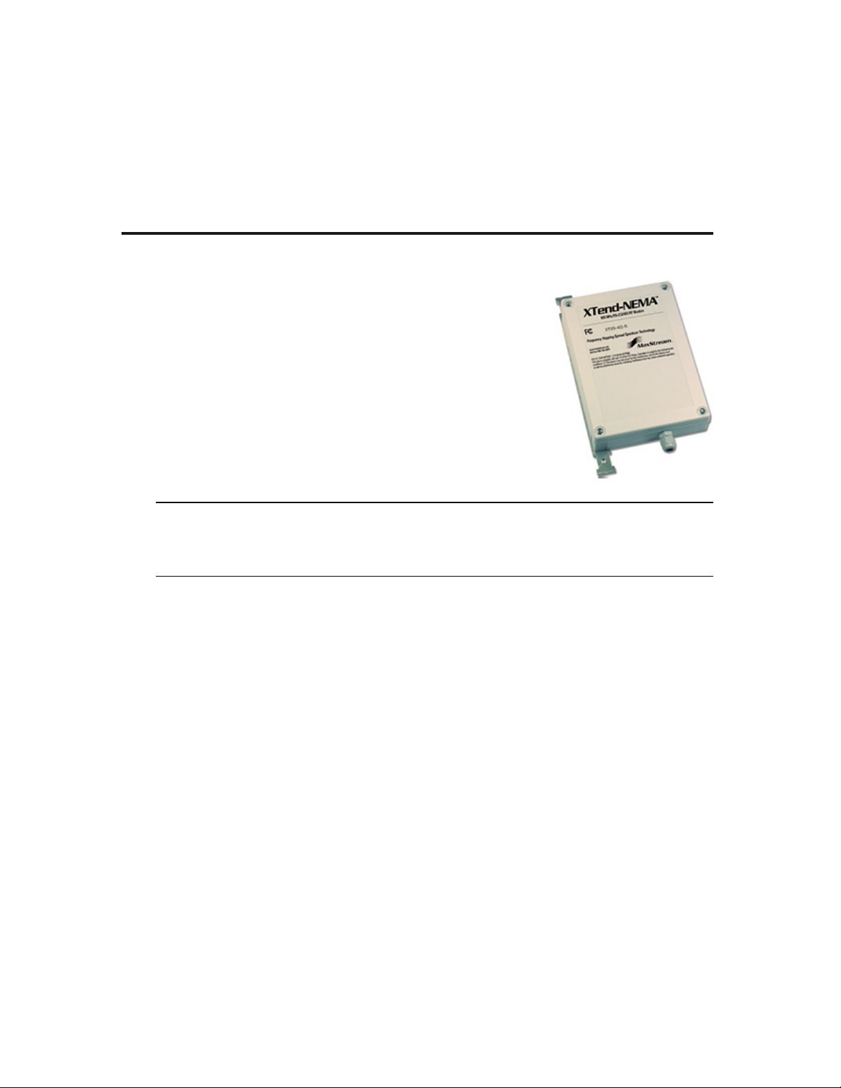
9XTend-NEMA™ Weatherproof RS-232/485 RF Modem
Introduction
Range Test Setup
Range Test Procedure
Optional Configurations
Create a long range wireless link in minutes.
www.maxstream.net
© 2005 MaxStream, Inc. All rights reserved.
WARNING: When operating with 1 Watt power output, transmitting in close
proximity of other RF modems can damage modem front-ends. Observe a minimum
separation distance of 2' (0.6 m) between modems.
Refer to the 9XTend-PKG-R RS-232/485 product manual for information regarding
operation of the 9XTend-NEMA RF Modem.
MD0025
Page 2
Introduction
This guide provides step-by-step instruction on how to setup a wireless link and test
the modem's ability to transport data over varying ranges and conditions.
Range Test Setup
Requirements for Range Test
1 XTend-NEMA Weatherproof RS-232/485 RF Modem
1 XTend-PKG-R RS-232/485 RF Modem (or a second XTend-NEMA)
1 PC (Windows 98 SE, 2000 or XP) loaded with X-CTU Software
Accessories (CAT5 cable with DB-9/PWR adapter board, loopback adapter, 2 RPSMA
antennas (one is inside the NEMA enclosure), 2 power supplies)
Install X-CTU Software
Double-click "setup_X-CTU.exe" file and follow prompts of the installation screens.
This file is located on the MaxStream CD and under the 'Software' section of the
following web page: www.maxstream.net/helpdesk/download.php
The X-CTU software interface is divided into the following four tabs:
• PC Settings - Setup PC com ports to interface with the RF modem
• Range Test - Test RF modem's range under varying conditions
• Terminal - Read/Set RF modem parameters and monitor data communications
• Modem Configuration - Read/Set RF modem parameters
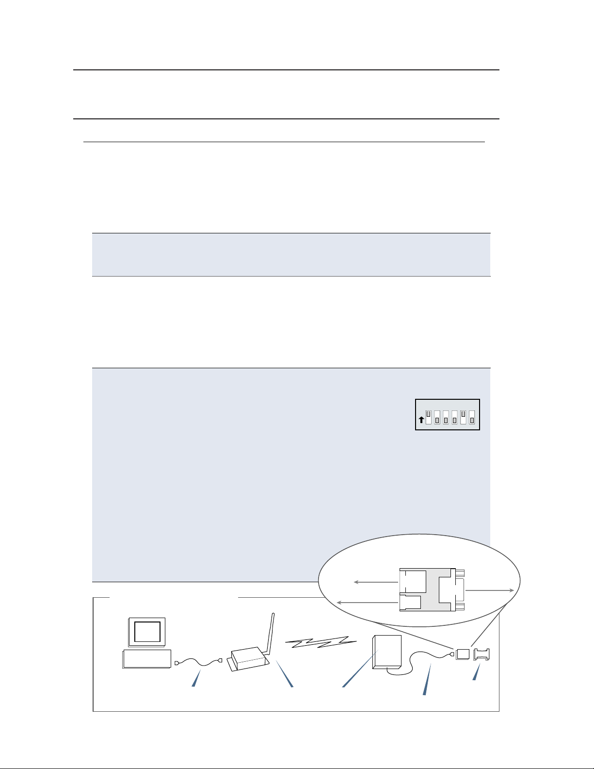
Hardware Setup
The XTend-NEMA RF Modem (remote) will be referred to as “NEMA”. The
XTend-PKG-R RF Modem (base) will be referred to as “PKG-R”.
1. Verify DIP Switches of NEMA & PKG-R are set to their default
positions (RS-232, Point-to-point Mode: Switches 1 and 5
1 2 3 4 5 6
O
N
are ON (up) and the remaining 4 switches are OFF (down)).
[Refer to back page for important information regarding the DIP switch.]
2. Connect the female DB-9 connector of the PKG-R to the male DB-9 connector
of the host PC using an RS-232 cable [Figure 1].
3. Attach the serial loopback adapter to the female DB-9 connector of NEMA.
The serial loopback adapter configures the NEMA to function as a repeater
by looping data back into the modem for retransmission. [Figure 1]
4. Attach RPSMA antenna to PKG-R. (NEMA antenna is inside the enclosure.)
5. Power NEMA through the DB-9/PWR adapter
NEMA
DB-9/PWR
RJ-45
DB-9
PWR
board and the PKG-R through its power
connector using the included power
supplies.
Figure 1. Hardware Setup
Adapter Board (top view)
Power Supply
Loopback
Adapter
Host PC
RS-232 cable
PKG-R
RPSMA antennas
NEMA
CAT5 cable
Loopback
adapter
Page 3

Range Test Procedure
Use the "PC Settings" and "Range Test” tabs of the X-CTU Software to:
•
Setup a PC Serial Com Port for communications with the
XTend RF Modem [step 2 of "Range Test"].
Determine RF modem's range [steps 1-8 of "Range Test"].
•
Range Test
1. Launch the X-CTU Software (
Under the "PC Settings" tab [Figure 2], select the PC serial com port from
2
Start --> Programs --> MaxStream --> X-CTU)
the dropdown list that will be used to connect to NEMA.
3
Select the PC interface baud rate that matches the RF data rate of NEMA.
Use default values for remaining fields [Figure 2].
4. Select the “Range Test” tab [Figure 3].
5
(Optional) Check the box in the ‘RSSI’ section to enable its display.
6
Click the ‘Start’ button to begin range test.
7. Move the remote PKG-R (with loopback adapter) away from NEMA to
determine the range of the wireless link.
Figure 2. PC Se�ings tab
PC Com Port
2
Default Values
3
Default RF data rate is 9600 baud
Other Default Values:
Flow Control
Data Bits = 8
Parity
Stop Bits = 1
= None
= None
.
(Packet Information)
Figure 3 Range Test tab
RSSI checkbox
5
RSSI stands for “Received Signal Strength Indicator”
Start/(Stop) button
6
Page 4

Optional Configurations
Out-of-box, the XTend-NEMA RF Modem is configured to provide immediate wireless
links between devices. The modem's default configuration supports a wide range of
RF communications.
If the RF Modem must be configured to support specific needs of a data system,
many programming options are available. The RF modem recognizes an extensive
set of AT and binary commands. Several of the commands can be sent to the
modem using the DIP Switch that is located inside the weatherproof enclosure.
Using the RF Modem DIP Switch
The DIP switch allows users to configure the several RF modem settings.
Figure 4. DIP Switch Se�ings (Se�ings applied only when powering on)
1 2 3 4 5 6
O
N
Serial Interface
Switches 1 & 2
1 2
= RS-232
= 2-wire RS-485
4-wire
=
RS-485/422
= Restore Defaults
RS-485/422
Termination
(Optional) Switches 3 & 4
3 4
2-wire RS-485
=
Termination
4-wire RS-485/422
=
Termination
None
=
= not used = User Defined
TX/RX Mode
Switches 5 & 6
5 6
= Point-to-Point
Multipoint-
=
Base
Multipoint-
=
Remote
Each time the RF modem is powered on, the modem is automatically configured
according to the positions of the DIP Switch. For example, the default positions
(switches 2 and 5 are ON (up)) cause the DT and MY parameters to be set to
specific values each time the RF modem is powered up.
To disable automatic configurations (so modified parameters persist in the modem
registry on subsequent power-ups), set swiches 5 and 6 to their ON (up) positions.
Restoring Modem Defaults
If the XTend Modem
is not responding or
cannot enter into
Command Mode, try
restoring the modem
to its original default
parameter values.
To Restore Defaults
1. Set switches 1 & 2 of the DIP Switch to
their ON (up) positions and the remaining four
switches to their OFF (down) positions.
2. Turn off, then on again, the power supplying the
XTend-NEMA RF modem.
(DIP Switch Method):
= ON (up)
= OFF (down)
Other Configuration Options
Using the DIP Switch to configure the modem is one of several ways to configure
modem parameters. Other programming options are available such as using the
X-CTU Software "Terminal" and "Modem Configuration" tabs. Binary programming
is also supported.
Since the XTend-NEMA and XTend-PKG-R RF modems operate and behave the
same, refer to the XTend-PKG-R RF Modem product manual for more information
about supported configuration options.
Contact MaxStream (Office hours are 8am – 5pm U.S. Mountain Standard Time)
Phone: (801) 765-9885, Live Chat: www.maxstream.net, E-Mail: rf-xperts@maxstream.net
 Loading...