

Page 1
Page 2

USER Manual
TABLE OF CONTENTS
1 DX-3000 ..................................................................... 5
1.1 INTRODUCTION ...................................................................................... 5
1.2 S
1.3 LABEL AND MARKING SYMBOLS ................................................................. 7
1.4 D
YMBOLS USED IN THIS MANUAL .............................................................. 6
EVICE LABELING .................................................................................... 8
2 WARNINGS AND INSTRUCTIONS ....................... 9
2.1 SYMBOLS AND DETAILS ............................................................................. 9
2.2
2.2.1 Warnings for product use .................................................................................. 9
2.2.2 Warnings for battery use ................................................................................. 10
2.2.3 Warning for product inspection ....................................................................... 10
2.3 WARNINGS FOR STORAGE ....................................................................... 10
WARNINGS FOR USE ................................................................................ 9
3 CAUTION AND INSTRUCTIONS ........................ 12
3.1 SYMBOLS AND DETAILS .......................................................................... 12
3.2 C
3.2.1 Caution for product storage ........................................................................... 12
3.2.2 Caution for product use .................................................................................. 12
3.3 CAUTION OF OTHER MATTERS ................................................................. 13
AUTION AND INSTRUCTIONS ................................................................. 12
4 ITEMS TO CHECK ................................................. 14
4.1 SYMBOL AND DETAIL ............................................................................ 14
4.2 I
TEMS TO CHECK .................................................................................. 14
1
Page 3

USER Manual
5 PRODUCT FEATURES ........................................... 15
5.1 OUTLINE ............................................................................................. 15
PRODUCT FEATURES .............................................................................. 15
5.2
5.2.1 Features ........................................................................................................... 15
5.3 PRODUCT SPECIFICATIONS ...................................................................... 16
5.3.1 Device main body ........................................................................................... 16
5.3.2 Battery Pack ..................................................................................................... 16
5.3.3 Battery pack charging adapter ........................................................................ 17
5.3.4 Battery charging cradle ................................................................................... 17
6 PRODUCT COMPOSITION .................................. 18
6.1 OUTLINE ............................................................................................. 18
PRODUCT COMPOSITION ........................................................................ 18
6.2
PRODUCT EXPLANATION ........................................................................ 20
6.3
6.3.1 Main body name ............................................................................................. 20
6.3.2 UI screen composition and functions ............................................................. 21
6.3.3
6.3.4
Buttons and functions ..................................................................................... 24
Battery pack and charging devices ................................................................. 26
7 HOW TO USE ........................................................ 29
7.1 POWER ON/OFF .................................................................................. 29
7.2 X-ray EXPOSURE POSITIONING .............................................................. 30
7.2.1 Patient’s positioning ........................................................................................ 30
7.2.2 Film or intraoral sensor positioning ................................................................ 31
7.2.3 DX-3000 positioning ......................................................................................... 32
7.3 X-ray EXPOSURE ................................................................................ 32
7.3.1 X-ray exposure sequence .............................................................................. 32
7.3.2
Setting X-ray Exposure time ......................................................................... 34
2
Page 4

USER Manual
7.4 ENVIRONMENT SETUP ............................................................................ 35
7.4.1 Environment setup screen ............................................................................... 35
7.4.2 Environment setup list .................................................................................... 36
7.5 FUNCTION SETUP .................................................................................. 38
7.5.1 Function setup screen ..................................................................................... 38
7.5.2 Function setup list ........................................................................................... 38
7.6 WIRED REMOTE CONTROLLER ................................................................. 41
7.6.1 Wired remote controller usage ....................................................................... 41
7.7 BATTERY ............................................................................................. 42
7.7.1 Mounting battery inside Main body ............................................................... 42
7.7.2 Battery level and charging .............................................................................. 43
8 MAINTENANCE AND STORAGE ....................... 47
8.1 MAINTENANCE AND STORAGE ................................................................ 47
8.2
8.2.1 Check for Product storage .............................................................................. 48
8.2.2 Charging adaptor and cradle storage ............................................................ 48
STORAGE ............................................................................................ 48
8.3 PRODUCT TRANSPORT, STORAGE CONDITIONS AND CONDITIONS OF USE ........48
8.3.1 Transportation and storage conditions .......................................................... 48
Optimal conditions of use ............................................................................... 49
8.3.2
8.4 ITEMS TO CHECK ................................................................................... 49
8.4.1 Frequent inspection items ............................................................................... 49
Periodic inspection items ................................................................................ 49
8.4.2
9 INSPECTION ITEMS BEFORE REPAIR ................50
9.1 CHECK ITEMS BEFORE REQUESTING INSPECTION .......................................... 50
TROUBLESHOOTING ............................................................................... 52
9.2
3
Page 5

USER Manual
10 PRODUCT SPECIFICATION AND QUALITY
ASSURANCE ................................................................ 53
10.1 PRODUCT SPECIFICATION ....................................................................... 53
10.2 Q
UALITY ASSURANCE ............................................................................ 54
11 DX-3000 TECHNICAL DOCUMENT ..................... 55
11.1 HIGH VOLTAGE GENERATOR .................................................................... 55
11.1.1 X-ray Tube : Toshiba D-081B ......................................................................... 55
11.2 ELECTROMAGNETIC COMPATIBILITY .......................................................... 57
11.3 R
ADIATION PROTECTION ........................................................................ 58
4
MANUAL VERSION 3.0
Revision date: May/2014
Page 6
USER Manual
1 DX-3000
1.1 Introduction
Thank you for purchasing the portable X-ray system from Iridium Dental. The
DX-3000 has been developed to not only take radiographs in an analog fashion using
conventional film, but also to be used in Dental Digital Radiography (DDR) using a digital
sensor. Please familiarize yourself with this manual and the X-ray unit prior to use.
Follow all product-use instructions while using the product.
PRODUCT USAGE
This product is a medical device, and it should only be used as a digital X-
ray radiography device for X-ray radiography in the proper facility.
WARNING
This X-ray unit may be dangerous to the patient and operator unless
safeexposure factors and operating protocol are observed.
TYPE B Applied Part
A "Type B Applied Part" provides the lowest degree of patient
protection and is not suitable for direct cardiac application.
CAUTION
For proper usage and safety purposes, please ensure that only legally
qualified personnel (Doctor, Medical Treatment Radiological Technologist,
Medical Treatment X-ray Technologist) may use this product after it
has been fully familiarized by the contents of this user manual.
5
Page 7
USER Manual
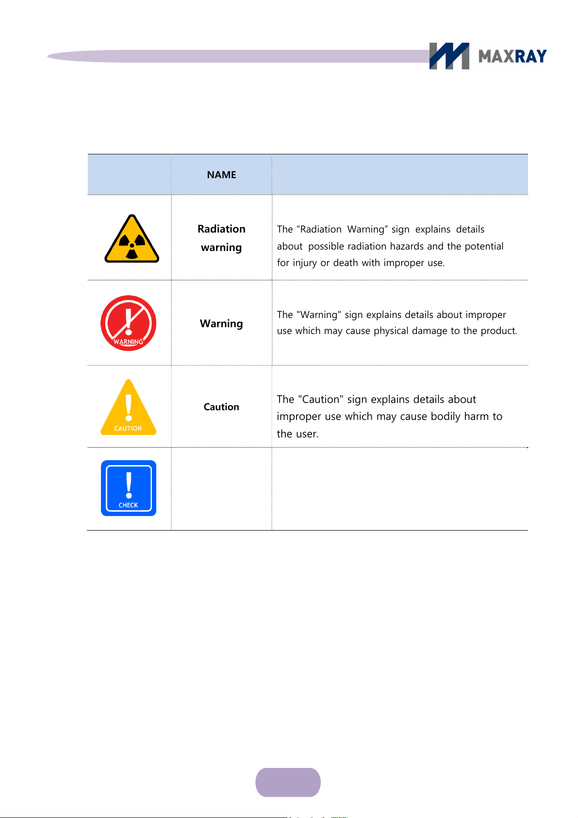
1.2 Symbols used in this Manual
SYMBOL NAME DETAIL
Radiation
warning
Warning
Caution
Check
The “Radiation Warning” sign explains details
about possible radiation hazards and the potential
for injury or death with improper use.
The "Warning" sign explains details about improper
use which may cause physical damage to the product.
The "Caution" sign explains details about
improper use which may cause bodily harm to
the user.
The "Check" sign explains instructions that users
must follow for product installation, operation, and
maintenance.
6
Page 8
USER Manual
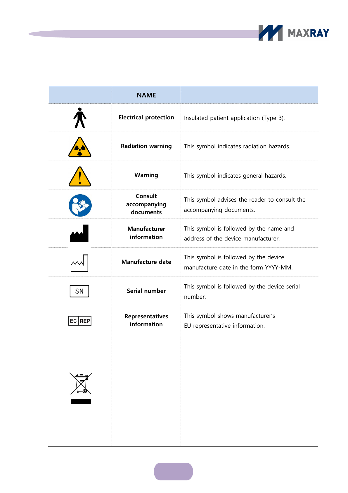
1.3 Lables and markings: Symbols
SYMBOL NAME DESCRIPTION / FUNCTION
Electrical protection
Radiation warning
Warning
Consult
accompanying
documents
Manufacturer
information
Manufacture date
Serial number
Insulated patient application (Type B).
This symbol indicates radiation hazards.
This symbol indicates general hazards.
This symbol advises the reader to consult the
accompanying documents.
This symbol is followed by the name and
address of the device manufacturer.
This symbol is followed by the device
manufacture date in the form YYYY-MM.
This symbol is followed by the device serial
number.
Representatives
information
Separate collection
for electrical and
electronic equipment
This symbol shows manufacturer’s
EU representative information.
Indicates the need for separate collection of
electrical and electronic equipment in
compliance with the Waste Electrical and
Electronic Equipment (WEEE) Directive. This
symbol indicates that electrical and electronic
equipment wastes must not be disposed as
unsorted municipal waste and must be collected
separately. Please contact the manufacturer or
an authorized disposal company to
decommission your equipment according to
local regulations
7
Page 9

USER Manual
1.4 Device labeling
8
Page 10

USER Manual
2 Warnings and instructions
2.1 Symbols and details
The "Warning" sign explains details about improper use which may cause
physical damage to the product.
2.2 Warnings for use
2.2.1 Warnings for product use
Ensure that the radiation exposure limit required for image diagnosis is not exceeded.
If radiation exposure safety regulations and operation-related guidelines are not
followed during use of this product, both patient and operator may be at risk.
Only legally qualified personnel are permitted to operate this device.
Use this device only for its designated purpose.
If any abnormalities are found with the patient while using the device, stop using the
device immediately and ensure patient safety.
Do not make any modifications to the device.
If you suspect any product malfunctions (such as oil leakage) while using the product,
turn off the power immediately and contact the closest customer support center.
Make sure a fire extinguisher is on-site in case of a fire emergency.
9
Page 11

USER Manual
2.2.2 Warnings for battery use
Use only the provided designated battery!
Do not expose the battery to strong electrical currents, and keep it away from sharp
objects.
If the battery is kept under high temperature, it may explode.
Do not let the battery become wet or be kept in damp conditions.
Store batteries in a locked cabinet.
Do not allow the battery terminals to come into contact with any metallic substance or
surface.
2.2.3 Caution for product inspection
Do not touch the product, charger, or power plug with wet hands. Doing so may
cause an electric shock.
During the cleaning process of the product, do not use wet-wipe cloths or
spraying products. Only clean the product once the battery has been removed.
2.3 Warnings for storage
Moisture, salinity, dust, etc. can affect the performance of the device. Do not store
the device in places with such conditions.
Do not store the product in direct sunlight or places with frequent temperature changes
for long periods of time. Under these conditions, the voltage generator's
10
Page 12

USER Manual
cooling and insulating oil could shrink, swell, freeze, or overheat, causing critical
damage to device functions.
Do not store product with explosive gas or chemicals.
Do not leave the battery pack connected to the charger during storage. When the
battery is used or charged for too long, it may shorten battery lifespan or increase the
danger of explosion.
The device must be stored in the protection case. If kept elsewhere, it may
cause critical damage to device functions.
Do not place the device on a high shelf where it may become a falling hazard.
Do not store the device in the trunk of a car or a cargo van where it may be move
freely and become damaged. If it must be transported by vehicle, be sure that it is
secured tightly.
11
Page 13

USER Manual
3 Caution and instructions
3.1 Symbols and details
The "Caution" sign explains details about improper use which may cause
bodily harm to the user.
3.2 Caution and instructions
3.2.1 Caution for product storage
Moisture, salinity, dust, etc. can affect the performance of device. Do not store the
device in places where such conditions may be present.
Do not store the product in direct sunlight or places with frequent temperature changes
for long periods of time.
Do not store the product with explosive gas or chemicals.
Do not leave the battery pack connected with the charger during storage.
3.2.2 Caution for product use
Please maintain regular temperature and moisture levels for normal operation.
During use or transportation of the device, please be careful to avoid severe shocks or
vibration.
Wear a protective lead apron or equivalent radiation protection gear during use.
Keep the product clean for proper usage.
Use care when disconnecting the battery pack cradle from the charger.
12
Page 14

USER Manual
3.3 Caution for other matters
In the event that the device breaks down, mark it as such and send it to
a designated professional at the A/S center.
Do not let patients touch the device. Do not leave it unsupervised.
If the device is dropped, turn it off and remove the battery. Return the unit to the
manufacturer for inspection.
For discarding the product:
This symbol indicates the need for separate collection of electrical
and electronic equipment in compliance with the Waste Electrical and
Electronic Equipment (WEEE) Directive. This symbol indicates that
electrical and electronic equipment wastes must not be disposed as
unsorted municipal waste and must be collected separately. Please
contact the manufacturer or an authorized disposal company to
decommission your equipment according to local regulations.
13
Page 15

USER Manual
4 Items to check
4.1 Symbol and Detail
The "Check" sign explains instructions that users must follow for product
installation, operation, and maintenance.
4.2 Items to Check
Check the condition of the device and battery pack before using. Confirm
the that the device is operating properly.
Check the part that makes direct contact with patients for any abnormalities.
Use the device only in the designated sequence.
Use the device in a stable environment with good ventilation.
Check the remaining battery power display. If the remaining battery power is not
sufficient, recharge the battery prior to use.
Use the battery-pack charger exclusively for this product when charging.
not let metallic products or other foreign substances touch the battery pack
Do
terminals. Keep it clean by using a dry cloth.
Ensure that the device and all of its parts are regularly inspected.
14
Page 16

USER Manual
5 Product Features
5.1 Outline
In Chapter 5, the features and specifications of this device are explained for safe usage.
5.2 Product Features
5.2.1 Features
> Medical Device Name: Portable X-ray System
> Model Name: DX-3000
> Display: 2.5” LCD (Resolution: 128 x 64)
- Adult and child mode
- Film and digital mode
- Remaining battery life
- Exposure time setup by
> Function for user
- Film and digital mode selection
- Maximum or Minimum exposure time setup
- Exposure time unit setup
part of the teeth
- Single wired remote controller operation and exposure selection button
- Automatic shutoff time-setup
15
Page 17

USER Manual
- Continuation of LCD backlight time setup
> Removable and rechargeable battery supply.
5.3 Product specifications
5.3.1 Device main body
> Device Name: Portable X-ray System
> Tube voltage: 65 kV (Fixed)
> Tube current: 2.5 mA (Fixed)
> X-ray tube focal spot size: 0.8 mm
> Power consumption: 285 VA
> Cooling method: OIL Cooling Method
> Total filtration: Over 1.5 mmAl (inherent: 0.8 mmAl, fixed type added filter: 0.7 mmAl)
> Target Angle: 20˚
> Time setting function: 0.02 – 2.5 sec. (Including film / digital mode)
> Exposure time unit setting function: 0.01 – 0.1 sec.
> Distance to target: Distance between target and Focal Spot > 20 cm (8 [inch])
> Main body size: 166(L) x 240(W) x 82(H) mm (except length of cone)
> Main body weight (exclusion battery): 2.2 kg
5.3.2 Battery Pack
Model name: PF435060HP-4S
16
Page 18

USER Manual
Cell material: Lithium Polymer
Charging conditions
- Charging current: 1.0 [A]
- Charging voltage: DC 16.8 [V]
- Temperature range: 0 – 40 [℃]
Usage conditions
- Maximum output current: 26 [A]
- Output voltage: DC 15 [V]
- Temperature range: -20 – 60 [℃]
5.3.3 Battery pack charging adapter
Model name: BPL910S16N01
Input voltage: AC 100 – 240[V], 50/60 [Hz], 0.5 [A]
Output voltage: DC 16.8[V]
Output current: 1.0 [A]
5.3.4 Battery charging cradle
Model name: D910
Charging voltage: DC 16.8 [V]
Charging current: 1.0 [A]
Discharging voltage (at the time of battery connection): varies depending on
discharging condition.
Discharging current (at the time of battery connection): varies depending on
discharging condition
Size: 77.5(L) x 72.3(W) x 49.3(H) [mm]
17
Page 19

USER Manual
6 Product composition
6.1 Outline
In Chapter 6, specific product parts are explained. Be familiar with the entire manual
before using the device.
6.2 Product composition
The DX-3000 consists of the items below.
Main body: 1 ea
Battery pack: 2 ea
Battery charging adapter: 1 ea
Battery charging cradle: 1 ea
Power cord: 1 ea
Storage case: 1 ea
User Manual CD (includes product warranty) : 1 ea
Wired remote controller (sold separately): 1 ea
Back Scattered shield (sold separately): 1 ea
CHECK
The images in this document may differ from the actual product depending
on product function, federal and local regulations, and supply circumstances.
Consider the following only for reference.
18
Page 20

USER Manual
Main body
Battery charging cradle
Battery
Power cord
Battery charging adapter
Storage case
User Manual CD /
Product warranty
Wired remote controller
(sold separately)
Figure 6.1 Pr
Backscatter shield
oduct Composition
19
Page 21

USER Manual
6.3 Product Explanation
6.3.1 Main body parts
The parts of the main body are labeled as follows:
2.35” Graphic LCD
X-ray exposure
indicating light
Remote control
connector
Power button
Time setting button
Label
Hand strap
Low battery indicating light
X-ray exposure
button
Battery pack cover
X-ray field
Product logo
Figure 6.2 Main body parts
20
Page 22

USER Manual
6.3.2 User interface (UI) screen composition and functions
1
○ Main control screen
Adult tooth
Adult image
Child image
Status
Status of Battery
Exposure setting time
Remote mode icon
Child too
th
Time setting unit Film / digital mode icon
Figure 6.3 Main control screen
Adult image and adult tooth: Indicates recommended adult tooth by time setting.
Child image and child tooth: Indicates recommended child tooth by time setting.
Status: Indication of the present operation of the device.
Status of
battery: Indicates the remaining battery life by 4 steps.
Exposure setting time: Indicates X-ray irradiation time.
Film / digital mode icon: Apply ‘D’ in environment setup menu when using
digital sensor and apply ‘F’ when using film.
Time setting unit: Time unit is adjustable from 0.01 seconds to 0.1 seconds
and indicates the current setup.
Remote mode icon: When selecting remote control, an ‘"R" will appear.
21
Page 23

USER Manual
2
○
Environment Settings screen
To change the MENU
Film/digital mode setting
Automatic shutoff
setting
Backlight time setting
Battery level
Total exposure counts
MENU change: Indicates the menu options, which can be navigated by
pressing the ▲ button on the upper part of main body.
To change the value
of individual settings.
UI version
Figure 6.4 Environment settings screen
Value setting change: Indicates change of setup value, navigated by pressing
▼ button on upper part of main body.
Film / digital mode setting: Changes present exposure mode to film or digital
Automatic shutoff setting: Automatic
shutoff time is adjustable from 1 minute to
10 minutes, by 1 minute intervals.
Backlight time setting: The amount of time the blacklight remains on after any
button has been pressed is adjustable from 1 second to 10 seconds, by 1 second
intervals.
Battery level: Indicates the remaining battery strength.
22
Page 24

USER Manual
Total exposure counts: Indicates the number of x-ray exposures that have
occurred.
UI version: Indicates the current UI version number.
3
○ Function Setting Screen
Exposure button
enable / disable setting
Max exposure time setting
Exposure start time setting
Exposure time unit setting
Factory Defaults
Exposure button enable / disable setting: ‘Remote' appears when only the wired
remote controller must be used to begin exposure, whereas 'Dual' appears when
either exposure button can be used.
Max exposure time setting: The maximum exposure time setup is available
and adjustable from 1 second to 2.5 seconds, by 0.05 second intervals.
Exposure start time setting: The minimum exposure time setup is available
Figure 6.5 Function setting screen
and adjustable from 0.02 seconds to 0.2 seconds, by 0.01 second intervals.
Exposure time unit setting: Exposure time uni
t setup is available and adjustable
from 0.01 seconds to 0.1 seconds, by 0.01 second intervals.
Factory defaults: Returns all setup options to the initial factory settings.
23
Page 25

USER Manual
6.3.3 Buttons and functions
1
○ Top side buttons and functions
Power button: Used to turn on/off the device and as combination button to
enter the environment setup or function setup menus.
Time setting button: Used as the exposure time-set button on the main control
display and to switch between menus or change settings on the environment setup
and function setup menus. The functions of the exposure time-set button on the
different menu screens are displayed in Table 6-1.
Table 6-1.
Classification
Power button
Time setting button
Figure 6.6 Top side buttons and functions
Functions of time setting buttons
Environment setting
Main control screen Function setting screen
screen
Button sequence
to reach screen
▲ button
function
▼ button
function
Power button ON
Exposure time increase Menu change Setting change
Exposure time decrease Setting change Menu change
While the device is ON:
Power button + ▲button
While the device is ON:
Power button + ▼button
24
Page 26

USER Manual
○2 Front side exposure button and function
Figure 6.7 Front side exposure button
If ‘Dual’ is selected on the ‘exposure button enable/disable’ function setup
display, pressing and holding the exposure button will cause the X-ray exposure.
The X-ray exposure is accompanied by a tone while the button is engaged. The
irradiation will stop when the button is released. (DMS method - Dead Man Switch)
CHECK
Because the product only generates X-rays while the button is pressed,
releasing the button during the accompanying sound will suspend X-ray
generation.
25
Page 27

USER Manual
6.3.4 Battery pack and charging device parts
1
○ Battery pack parts
Battery pack label
Output terminal (+)
Output terminal (-)
Figure 6.8 Battery pack parts
Battery pack label: Indicates the battery model name, manufacturer's address
and serial numbers, as well as providing certain precautions.
Output terminal (+,-): Provides power when the battery pack is inserted into the
device.
2
○ Charging cradle parts
Charging terminals
Battery pack holder
Charge indication light
DC input connector
Figure 6.9 Charging cradle parts
26
Page 28

USER Manual
Charge indication light: Indicates the status of battery charge using three
different colors (red - charging; green - fully charged; yellow - charging error)
Charging terminals: Connect the output terminals of the battery pack to the
charging terminals of the charging cradle to charge the battery.
Battery pack holder: Holds the battery pack in place while its being charged.
DC input connector: Receives charging power from charging adaptor
Charge source jack: Provides DC output power from the adapter
2
○ Charging adaptor parts
Charge source Jack
(Top)
Output indicating light
AC Input
connector
Charging adaptor
label
(Bottom)
AC power cord
6.10 Charging adaptor parts
27
Page 29

USER Manual
Output indicating light: Indicates present output status.
AC input connector: Connect with the AC input of the power cord.
Charging adapter label: Indicates model name and input/output condition,
certification, serial numbers.
AC power cord: Connect to an external AC power source.
WARNING
The following rules must be followed whenever charging the battery pack:
(1) Use only the provided charger and battery pack. (2) Keep the battery
pack in the special storage case after it has been fully charged. (3)
Avoid over-charging the battery pack once it has been fully charged. (4)
Don't allow metal objects (coins, keys, clips etc.) to contact the battery
terminal plate.
CAUTION
The charge indicating light turns green once charging is complete.
Disconnect the battery pack and the power code while the charger set is
not in use.
CHECK
The battery pack is a consumable item, and its lifetime is
gradually reduced as it is used. Once the battery lifetime is reduced to
half of what it was upon purchase, replace it with a new battery pack.
CHECK
Used battery packs should not be thrown away. They should be
recycled or placed in an exclusive case.
28
Page 30

USER Manual
7 How to use
7.1 Power On/Off
After opening the battery cover at the bottom of the main body, insert the
battery pack, ensuring that it is inserted in the proper orientation.
Hold down the power button on top of the main body for 1 second. A green light
will appear along with a short beep, and the LCD window will display the
manufacturer's logo (see Figure 7.1).
Figure 7.
1 manufacturer’s logo
After the logo appears, the main control display (see Figure 7.2) will follow. The
exposure-time setting is indicated in the center of the main display. Users can adjust
the time setting by using the (▲▼) buttons on the top of the main body.
Holding the power button for 1 second will power off the device.
29
Page 31

USER Manual
Figure 7.2 main control display
CHECK
The DX-3000 has an automatic shutoff function in order to reduce
battery consumption. The automatic shutoff time is set for three minutes
after the device has not been used. The automatic shutoff time can be
adjusted by the user in the settings menu from 1 minute to 10 minutes,
in 1 minute intervals.
7.2 X-ray exposure positioning
7.2.1 Patient positioning
Place the patient in a chair and have them maintain bilateral symmetry.
Make sure the patient’s head is in a fixed position.
Exposing at 15~30˚ of patient’s position is recommended but the degree and
position can be adjusted according to user’s convenience. However, the patient
must not move during the exposure.
30
Page 32

USER Manual
7.2.2 Film or intraoral receptor positioning
X-rays generated by the DX-3000 can be detected by various receptors such as
film, intra-oral sensors (digital), PSP and viewed screens.
Place the film or sensor on the teeth and make sure it does not move.
If film or PSP is to be used, make sure they are not bent or twisted to avoid
image distortion.
Typically, the receptor should be aligned with the center of the X-ray cone,
perpendicular to the emitted X-rays (see Figure 7.3).
Teeth
Receptor
Figure 7.3 X-ray Panel display
DX-3000 cone
CHECK
The position of the film or intra-oral sensor and the face of the
DX-3000 must be parallel during exposure. If the angle deviates too
much, the image can be twisted and the correct image may be lost.
31
Page 33

USER Manual
7.2.3 DX-3000 positioning
The distance between the end of the cone and the patient must be within
at least 20cm (8 inch) from the X-ray focal spot.
The target teeth must be positioned at the center of the cone in order to
cover the whole tooth structure.
Operate the exposure appropriate for the image receptor and the teeth being
radiographed. Ensure the DX-3000’s cone is perpendicular to the receptor and that the
cone is pointed at the center of the teeth.
7.3 X-ray Exposure
7.3.1 X-ray exposure sequence
The DX-3000’s X-ray exposure sequence is as follows. Set up the user and
patient in a location that is optimal for radiography prior to exposure.
1
○ Set up the exposure time according to the recommendation for the target teeth
or to the user's preference.
2
○ Place the film or digital intra-oral sensor tightly inside the target teeth.
3
ut the cone of the device up to the target teeth and perpendicular to the film
○ P
or intra-oral sensor and
4
○ Hold the exposure button until exposure has finished and then place
press and hold the x-ray exposure button.
the device
in a safe place.
5
○ Check images from the fil
m or sensor after shooting.
32
Page 34

USER Manual
After pressing the exposure button, a tone warns that X-ray exposure has
begun, and X-ray exposure continues with a corresponding tone. X-rays are
only generated during the period of the consecutive tone and while the button
is held.
While X-rays are generated, the ‘READY’ signal on the upper LCD main
control display will change to the ‘EXPOSURE' signal, and the X-ray indicating light
on the front part of the main body will turn yellow.
Once the X-ray exposure has finished, the 'EXPOSURE' signal on the upper LCD
main control display will disappear and the yellow X-ray indicating light will turn
off.
After the X-ray exposure has finished, a ‘WAIT’ signal appears on the
upper LCD main control display and the device will prepare for the next X-ray
exposure over the course of 10 seconds. X
the wait period.
-ray exposure is not available during
CHECK
The modified time set is only saved after an X-ray exposure has occurred.
If, after changing the time set, no exposure is made, the time set reverts
to the default value automatically after the device is turned off.
CAUTION
X-rays are only generated while the X-ray exposure button is being
pressed. If the exposure button is released during the tone, exposure
stops immediately.
CAUTION
Avoid any potential materials which may attenuate the X-ray
beam between the X-ray cone and the target. This could cause image
distortion or a decline in the image quality.
33
Page 35

USER Manual
7.3.2 Setting X-ray Exposure time
The DX-3000’s X-ray exposure factors are fixed at 60 kV, 2.0 mA and is
changeable only by exposure time.
The DX-3000’s X-ray exposure time is adjustable from 0.02 to 2.5 seconds.
The exposure time is adjustable by 0.01 second intervals.
Set up the exposure time by pressing the exposure time set button.
Exposure time is decided by the teeth type, receptor type, and age of the
patient. Table 7-1 shows the time settings by teeth.
Table 7-1. Time set table by teeth
Classification Teeth types and exposure time
Age
Distance between
cone and skin
(20cm)
Adult - -
Child - -
Sensor
0.05 ~
0.10
0.15 ~
film
0.25
0.10 ~
0.15
0.25 ~
0.35
0.15 ~
0.20
0.45 ~
0.55
0.20 ~
0.25
0.60 ~
0.70
0.25 ~
0.30
0.70 ~
0.80
0.30 ~
0.35
0.80 ~
0.90
0.35 ~
0.40
0.90 ~
1.00
0.40 ~
1.00 ~
1.10
34
Page 36

USER Manual
CAUTION
Exposure time settings by teeth type can vary according to the sensor
type and film, distance to patient, and the image preference. Please refer
to the settings as recommendations only.
7.4 Environment setup
7.4.1 Environment setup screen
After turning on the device, press the power button and the ▲ button at the
same time to switch to the environment setting display (see Figure 7.4).
Figure 7.4 Environment setup display
Press ▲ button to move through menu.
Press ▼ button to change values.
After changing the desired settings, turn off the device and turn it back on. The
device will now operate under the changed settings.
35
Page 37

USER Manual
7.4.2 Environment setup list
MODE
Once you choose Film or Digital mode, the relevant teeth images for each
exposure sector are applied.
Press the ▲ button to select ‘MODE’ and press the ▼ button to choose ‘Film’
or ‘Digital’.
After selecting either ‘Film’ or ‘Digital’ and saving the settings,
‘F’(Film) or ‘D’(Digital) will appear on the main control display (see Figure 7.5).
Film Mode Digital Mode
Figure 7.5 Mode Setting
Power-save
If the device has not been used for some time, the power will automatically
shut off to avoid unnecessary power consumption.
The default time setting is 5 minutes and it is adjustable from 1 minute to 10
minutes, by 1minute intervals.
36
Page 38

USER Manual
Backlight
The LCD display backlight time is adjustable.
The default time is set to 1 second and it is adjustable from 1 second to
10 seconds, by 1 second intervals.
Bat
Battery life remaining is indicated on the display.
X-ray exposure is possible only when the battery level is from 14.0 V to 16.8 V.
Ver: Indicates the current software version in use.
Exp: Indicates the total number of X-ray exposures since counter reset.
37
Page 39

USER Manual
7.5 Function setup
7.5.1 Function setup screen
After turning on the device, press the power button and the ▼ button at the
same time for a second to reach the function setup display (see Figure 7.6).
Figure 7.6 Function setup screen
Press the ▼ button to move through the menu.
Press the ▲ button to change values.
After changing the desired settings, turn off device and turn it back on. The
device will now operate under the changed settings.
7.5.2 Function setup list
Expkey Set
Locks or unlocks the exposure button function. If locked (i.e. 'REMOTE'),
X-ray exposure is available by wired remote control only.
38
Page 40

USER Manual
Press the ▼ button to select ‘Expkey Set’ and the ▲ button to choose
‘Dual’ (exposure button enabled) or ‘Remote’ (exposure button disabled/
remote control use only).
When selecting 'Remote', 'R' will appear on the main control display and will
disappear when selecting 'Dual' (see Figure 7.7).
Remote controller use only
Figure 7.7 X-ray exposure button use check
MaxExp Time
Changes the maximum exposure time. It is adjustable from 1 second to 2.5
seconds, by 0.05 second intervals.
Press the ▼ button to select ‘MaxExp Time’ and press the ▲ button to adjust
the value (returns to 1s after 2.5s).
InitExp Time
Changes the minimum exposure time. It is adjustable from 0.02 seconds to
Exposure button enable
0.1 seconds, by 0.01 second intervals.
Press the ▼ button to select ‘‘InitExp Time’ and press the ▲ button to adjust
the value (returns to 0.02s after 0.1s).
39
Page 41

USER Manual
ExpUnit Time
Changes the time modification unit for exposure time. It is adjustable
from 0.01 seconds to 0.1 seconds, by 0.01 second intervals.
Press the ▼ button to select ‘ExpUnit Time’ and press the ▲ button to adjust
the value (returns to 0.01s after 0.1s).
The changed unit is indicated at the bottom center of the main control
display (see Figure 7.8).
Figure 7.8 Time modification unit display
40
Page 42

USER Manual
7.6 Wired remote controller
7.6.1 Wired remote control usage
Wired remote
control jack
Wired remote
control connector
Figure 7.9 Wired remote control connection
Connect the wired remote control connector to the wired remote control
jack on the front face of the DX-3000. The remote control jack has to be
connected completely inside the connector for proper operation.
Operating the device using the wired remote control follows the same procedure
as using the exposure button on the main body. The DX-3000 can be mounted on
a stand for prolonged X-ray exposure.
CAUTION
Only used approved wired remote controls. An approved remote
control is not included with the device, but can be purchased
separately from distributors.
41
Page 43

USER Manual
If the button is pressed after the exposure range has been adjusted, X-ray
exposure will occur.
The wired remote control only performs X-ray exposure. Other settings and
ations must be manipulated through the LCD screen on the device.
oper
7.7 Battery
7.7.1
Mounting the battery inside the main body
Check that the DX-3000 is powered OFF.
The battery pack cover should be separated by sliding it backward after holding
down the latch (circled in Figure 7.10).
Figure 7.10 Battery cover separation
After the battery cover has been removed, the battery cam should be
inserted into main body. The battery pack should be inserted in the direction of the
42
Page 44

USER Manual
arrow from the side of the main body, with the battery label face-down (see
Figure 7.11). The battery should fit into the slot's grooves smoothly.
Close the battery cover. The cover will connect with the main body and make a
clicking noise once it has properly been closed.
Turn the power on to confirm that the device is operating normally.
Direction of Insertion
Insert the battery with the
label face-down. The
battery slot will have
grooves for the battery to
slide into.
Figure 7.11 Main body battery pack insertion
7.7.2 Battery level and charging
The DX-3000’s battery has a high power output and, for safety purposes, is
designed to charge separately from the main body.
The user will be notified that it is time to charge the battery through either a
buzzing sound, the LCD screen, the low battery-indicating light or the low power
level upon powering up the device.
43
Page 45

USER Manual
When battery replacement is necessary, the battery level on the LCD display
indicates ‘LOW’ and a ‘LOW’ battery image appears on the upper right part
of the main control display. The battery replacement-indicating light on the
upper part of main body will be yellow, as well.
CHECK
Recharge the battery pack once the LOW battery sign on the
LCD screen is displayed. When changing the battery pack, take
care not to drop it and ensure it is inserted correctly.
The battery level display and remaining battery life shown on the right side
of the main control screen is demonstrated in Figure 7.12. Replace the
battery once the display indicates that 0~10% battery life remains.
81~100% 56~80% 31~55% 11~30% 0~10%
7.12 Battery level display/remaining battery life
If the device is used for too long after the 'LOW' battery signal began blinking,
the warning message in Figure 7.13 will appear on the LCD display for a few
seconds before the device powers off.
44
Page 46

USER Manual
Figure 7.13 LCD screen after battery dies
The battery charger consists of a charging adapter and a charging cradle (Figure 7.14).
Connect the charger adapter DC plug to the charging jack on the back side of
the charging cradle. Use a bundled AC power line to connect the charger adapter,
and connect it to AC power. The AC power voltage range and frequency is 100 -
220V AC and 50 - 60 Hz, respectively. Confirm the device is rated for the AC power
before connection.
Place the battery in the charge cradle (Figure 7.15). Insert the battery until it
fits smoothly into the groove of the charging cradle.
When charging has begun, a red light will be displayed on the charger cradle.
Once charging is complete, the red light will turn green.
If the battery is not correctly connected to the charger or another problem occurs,
the charge indicating light will be yellow.
45
Page 47

USER Manual
Figure 7.14 Battery cradle and charger adapter
① Connect the charger
DC plug to the back side
of the jack on the batter
cradle.
y
③ Charging begins after the battery is in place
② Fit the battery intro the cradle
in the direction shown here
Figure 7.15 Connecting the battery into the cradle
46
Page 48

USER Manual
8 Maintenance and storage
8.1 Maintenance
Keep the device and battery pack in a safe place where only qualified personnel have
access.
The collimating cone that comes into direct contact with the patient should be cleaned
by gently wiping with a clean cloth and rubbing alcohol.
Do not use the device near an active heater, heating device, etc.
Be sure to keep the DX-3000 and all parts in its storage cases while they aren't in use.
Do not alter the device. If the SEAL attached to the product is broken, free
A/S services will not be provided.
To ensure safe operation, perform regular check ups of the device and its parts with a
designated A/S center.
Avoid use/storage in places with the following characteristics:
- High moisture
- Direct sunlight
- Dusty/dirty
- High humidity
- No ventilation
- High salinity
- Chemical substances or explosive gases
47
Page 49

USER Manual
8.2 Storage
8.2.1 Checks for Product storage
Avoid places with high humidity or direct sunlight.
Avoid place with lots of dirt and dust, as well as sloped surfaces.
Do not store in extremely high or low temperatures.
Remove the battery and store it and the device separately if they are not to be used
for an extended period of time.
8.2.2 Charging adaptor and cradle storage
Do not allow foreign substances near the charge cradle terminal. Wipe it gently with
a cotton swab or soft cloth before use/storage.
Don't allow the battery pack charger to contact metallic substances (coins, keys,
clips, etc).
Do not use any batteries other than those designed for use with the charger provided.
8.3 Product transportation, storage conditions, and conditions of use
8.3.1 Transportation and storage conditions
Temperature: 0 ~ 40 ℃
Relative humidity: 30 ~ 75 %
Atmospheric pressure: 700 ~ 1060 Hpa
48
Page 50

USER Manual
8.3.2 Optimal conditions of use
1.
Temperature: 10 ~ 30 ℃
Relative humidity: 30 ~ 60 %
2.
Atmospheric pressure: 900 ~ 1060 Hpa
3.
8.4 Items to check
8.4.1 Frequent inspection items
When turning powering on the product, confirm that the power-on sound is heard
and that the normal initial screen is displayed.
Exposure-time settings are changed by using the time setting buttons. Confirm that
the time may be changed normally.
During X-ray exposure, confirm that the tone is heard, and that the exposure
indicating light turns to yellow.
While charging the battery pack, check the charge indicating light on the cradle to
confirm normal operation.
8.4.2 Periodic inspection items
Confirm that the fully charged battery lifetime is sufficient. Purchase a new
battery pack if the lifetime is half that of original lifetime.
CHECK
The battery pack is a consumable item, and the lifetime is gradually
reduced as it is used. If the lifetime is shortened to less than half of
what it was when it was first used, purchase a new batter pack.
49
Page 51

USER Manual
9 Inspection items before repair request
9.1 Check items before requesting inspection
If an abnormality is found with the product, confirm the following items before requesting
inspection.
Symptom Steps to take
After powering on,
tone is not heard and
LCD screen does not
display.
After powering on,
the tone is heard
but the LCD screen
does not display.
Power defect
While using (including
X-ray exposure), the
power turns off
automatically.
Confirm that the battery is inserted correctly or
replace it with a charged battery.
Separate the battery from the product to prevent
discharge while not in use.
After checking the remaining battery life, replace it
with a charged battery. If the screen is still not
displayed, contact designated A/S center.
Check
the remaining battery life.
Check the fully charged battery lifetime. If the lifetime
is less than half that of the orig
the battery with a new battery pack.
The product has an automatic shutoff function to
reduce battery consumption; check it's setting.
inal lifetime, replace
When X-rays are
emitted, but
exposure tone is
not heard.
Exposure defect
Check if ‘Remote’ mode is selected at Function Setup
menu. Exposure button operates in ‘Du
Check that the LCD display shows main control
screen status. X-rays are emitted with main control
display only.
al’ mode only.
50
Page 52

USER Manual
Symptom
Low battery sign is
displayed on the
LCD screen
Others
Battery won't
charge
Steps to take
Check remaining battery life, and replace it with a
charged battery pack, if needed.
Check the battery connection and be certain that
the battery pack cover is closed.
Check the charg
charger and cradle. The plug socket of adapter and
connector must be completely connected to charge
the battery.
If the charge indicating lig
cradle is red while charging, the battery is still
charging, and is done when the light is green. In case
the indicating light is yellow (indicating an error), try
to connect the battery and charger again.
e indicating light on the battery
ht on the battery charging
Confirm the battery charging
are connected accurately.
cradle and battery pack
51
Page 53

USER Manual
9.2 Troubleshooting
Problem Cause Solution
No battery pack. Insert battery pack.
Nothing lights up
Low battery. Charge the battery.
No X-ray emission
X-ray emission
works, but
exposure is too
light or
white
co
mpletely
Generator is preparing an
exposure. Displays “WAIT”.
“Remote” mode.
Button defective.
Receptor defective.
Exposure is positioned
incorrectly.
Exposure time is too short Increase the exposure time
Wait for X-ray exposure to be
ready (about 10 seconds).
Connect the
control or change “Expkey Set”
to “Dual” on the function setting
screen.
Call a qualified service
technician.
Change the receptor or compare
with another receptor.
Adjust the position of the
exposure.
wired remote
X-ray emission
works, but
exposure is too
dark
Device defective.
Receptor defective.
Exposure time is too long Decrease the exposure time
Device defective.
Call a qualified service
technician.
Change the receptor or compare
with another receptor.
Call a qualified service
technician.
52
Page 54

USER Manual
10 Product Specification and Quality Assurance
10.1 Product Specification
Classification
Product name
Input power
B-type application
Waterproof rating
Mode of operation
Tube voltage
Tube current
Focal spot size
Power consumption
Input voltage
Battery Pack
Details
Portable X-ray System
Use the internal power supply (Battery)
Cone
IPX0 (General Equipment)
Continuous operation
60 kV (Fixed)
2.0 mA (Fixed)
0.8 mm
285 VA (max.)
DC 15V
Lithium-polymer 4 Cell 1050 mAh Large Capacity
Cooling method
Total Filtration
Target angle
Time setting
Distance to target
X-ray field
Size of main body
Weight of body
Oil Cooled
More than 1.5 mmAl (Inherent Filtration: 0.8 mmAl, Fixed
added filter: 0.7 mmAl)
20˚
0.02 ~ 2.5[sec] (minimum unit 0.01sec)
Distance between target and Focal Spot > 20 cm (8 inch) 60
mm Round
240(L) x 166(W) x 82(H) mm
2.2 kg (excluding battery)
3
53
Page 55

USER Manual
10.2 Quality assurance
Product Quality Assurance Certificate
Medical
device name
Manufacturing
number
Customer
name
Customer
Address
Place of
purchase
Portable X-ray System
E-mail
1. This product is manufactured under a strict quality assurance standard and
inspection process.
2. If breakdown occurs during the warranty period under normal usage, free repair
services will be provided.
3. If breakdowns are due to incorrect usage or negligence, there will be charges for repair
Type name
Manufacture
date
Contact
information
Warranty
Period
Purchase date
DX-3000
1 year after purchase
services even if this occurs within the warranty period.
4. If you have questions or product related inquiries, please contact Dexcowin Co., Ltd.,
customer service center.
For better management of quality and customer service, fill out all of the above, and fax
or email our company.
Phone +82-02-2027-2880 Fax +82-02-2027-2884
Address: 606-ho, 2, Gasan digital 1-ro(Woorim Lions Vally 2), Geumcheon-gu,
Seoul, Korea
54
Page 56

USER Manual
11 DX-3000 Technical Document
11.1 High voltage generator
11.1.1 X-ray Tube : D-081B
1. Manufacturer: TOSHIBA(Japan)
2. Electrical Characteristics
Operating Tube Voltage ………………………………………………………………….60 kV
Focal Spot ……………………………………………………………………………..………0.8 mm
Input Power (at 1.0s) ……………………………………………………………………....600 W
3. Mechanical Characteristics
Dimensions
Figure 11.1 Dimension of the X-ray tube
55
Page 57

USER Manual
Target angle …………………………………………………………………………20 Degrees
Target material …………………...........……………………………………………Tungsten
Inherent Filtration ………………………At least 0.8 mmAl equivalent at 50kV
Anode Thermal Characteristics
Figure 11.2 Anode Heating/Cooling curve
4. Absolute Maximum and Minimum Ratings
Maximum Tube Voltage ……………………………………………………….……….... 65 kV
Maximum Inverse Tube Voltage…………………….………………..…………….... 75 kV
Minimum Tube Voltage ………………………………………………………..……….... 50 kV
Maximum Tube Current ………………………………………………..………………… 19 mA
Filament Voltage………………………………………………………………………. 2.9 ~ 4.0 V
Maximum Filament Current ……………………………………………………………. 2.0 A
Maximum Exposure Time ……………………………………………………………….. 10 sec
56
Page 58

USER Manual
Figure 1
Maximum tube current curve by exposure time
1.3
11.2 Electromagnetic compatibility
The DX-3000 has been tested and found to comply with the limits for medical
devices in IEC/EN 60601-1-2. These limits are designed to provide reasonable
protection against harmful interference in a typical medical installation. This equipment
generates, uses and can radiate radiofrequency energy and, if not installed and
used in accordance with the instructions, may cause harmful interference with other
devices in the vicinity. However, there is no guarantee that interference will not occur
in a particular installation. If the equipment does cause harmful interference with
other devices, which can be determined by turning the equipment off and on, the user is
encouraged to try to correct the interference by one or more of the following measures.
Reorient or relocate the receiving device.
Increase the separation distance between the equipment.
Consult the manufacturer or field service technician for help.
57
Page 59

USER Manual
11.3 Radiation Protection
The DX-3000 is compliant with the regulatory limits on radiation safety and protection
as defined in IEC60601-1-3, IEC60601-2-28, and IEC60601-2-65.
The device operator must protect him/herself with a lead apron or separating wall.
The patient must be provided protective materials such as a lead apron and thyroid
collar during exposure.
The device must only be operated inside the X-ray protecting facility.
The operator must monitor the status of the patient in case of an emergency.
The operator should immediately stop operating the device if any problem occurs.
Pregnant women and the parents of children must be made aware of their increased
risks of X-ray exposure.
58
 Loading...