

Maxrad MPRC2423, MPRC2449, MPRC3649, MPRC3623 Installation Manual
471 Brighton Drive
Bloomingdale, IL 60108
MPRC Parabolic
Antenna Series
©2007 PCTEL, Inc.
Broadband Technology Group - Antenna Products
All Rights Reserved
MIS-MPRC-1
Revision A
Printed in the U.S.A.
PRODUCT WARRANTY
A. General Warranty. PCTEL, Inc (“PCTEL”) represents and warrants that the Products furnished hereunder shall be free from
defects in material and workmanship for a period of two (2) years
from the date of shipment by PCTEL under normal use and operation. PCTEL sole and exclusive obligation under the foregoing warranty shall be to repair or replace, at its option, any defective Product that fails during the warranty period. The expense of removal
and reinstallation of any item is not included in this warranty. THE
FOREGOING WARRANTY IS EXCLUSIVE AND IN LIEU OF ALL
OTHER WARRANTIES, EXPRESS OR IMPLIED, INCLUDING THE
IMPLIED WARRANTIES OF MERCHANTABILITY AND FITNESS
FOR A PARTICULAR PURPOSE AND ANY WARRANTIES ARISING
FROM A COURSE OF DEALING, USAGE OR TRADE PRACTICE
WITH RESPECT TO THE PRODUCTS. Repair or replacement in
the manner provided herein shall be the sole and exclusive remedy
of Buyer for breach of warranty and shall constitute fulfi llment of all
liabilities of PCTEL with respect to the quality and performance of the
Products. PCTEL reserves the right to inspect all defective Products
(which must be returned by Buyer to PCTEL factory freight prepaid). No Products will be accepted for replacement or repair without obtaining a Return Materials Authorization (RMA) number from
PCTEL Customer Service [by telephone: 630.372. 6800 or email:
antenna.techsupport@pctel.com]. Products returned without an RMA
number will not be processed and will be returned to Buyer freight
collect. PCTEL shall have no obligation to make repairs or replacement necessitated by catastrophe, fault, negligence, misuse, abuse,
or accident by Buyer, Buyer’s customers or any other parties. The
warranty period of any repaired or replaced Product shall not extend
beyond its original term.
B. Warranty Conditions. The foregoing warranty shall apply only if:
(i) the Product has been properly installed and used at all times in
accordance, and in all material respects, with the applicable Product
documentation; (ii) no modifi cation, alteration or addition has been
made to the Product by persons other than PCTEL or PCTEL’s authorized representatives or otherwise approved by PCTEL; and (iii)
the Product has not been subjected to misuse, neglect or unusual
physical, electrical or electromagnetic stress, or some other type of
accident. C. Disclaimer. PCTEL DOES NOT WARRANT THAT THE
OPERATION OF THE PRODUCTS IS ERROR-FREE OR THAT
OPERATION WILL BE UNINTERRUPTED. IN NO EVENT SHALL
PCTEL BE RESPONSIBLE FOR DAMAGES OR CLAIMS OF ANY
NATURE OR DESCRIPTION RELATING TO (i) SYSTEM PERFORMANCE, INCLUDING COVERAGE, (ii) BUYER’S SELECTION OF
PRODUCTS FOR BUYER’S APPLICATION AND/OR (iii) FAILURE
OF PRODUCTS TO MEET GOVERNMENT OR REGULATORY
REQUIREMENTS.
RETURNS
In the unlikely event a defect occurs in this product, please work
through the dealer or distributor from which this product was purchased. PCTEL, Inc. provides complete service and support to all of
its dealers and distributors.
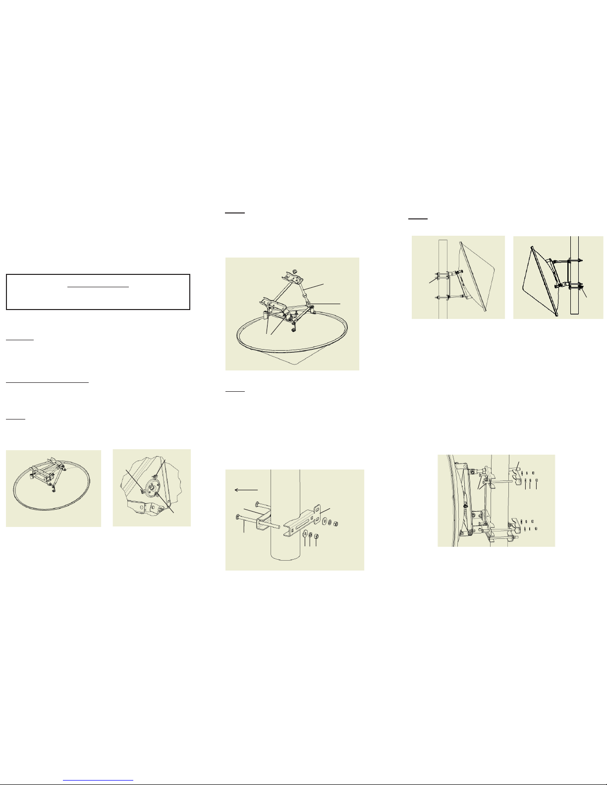
P00263 Contents:
(A) 1 - azimuth fi ne adjustment bar
(B) 1 - 3/8” x 16 x 1” hex head bolt
(C) 3 - 7/16” ID x 1” OD fl at washer
(D) 3 - 3/8” split lock washer
(E) 3 - 3/8” - 16 hex nut
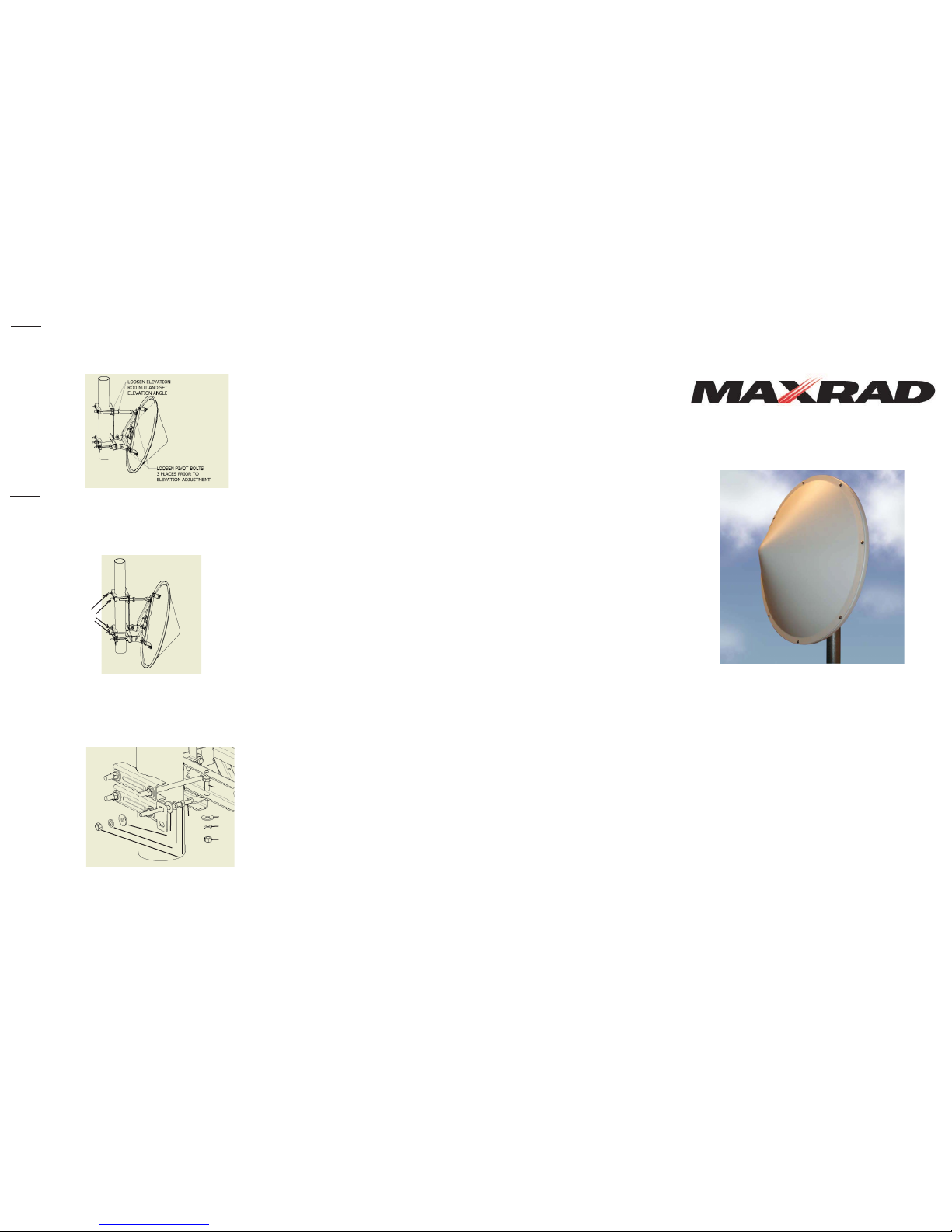
Step 5.
Elevation adjustment.
Loosen pivot bolts (3 locations). Loosen elevation rod nut and set
elevation angle.
Step 6.
Azimuth adjustment. Loosen bracket nuts and rotate antenna on
mounting pipe for proper azimuth positioning.
Attach fi ne azimuth adjustment kit P00263. Loosen bracket nuts (4
locations). Turn azimuth rod nut and set azimuth angle.
C
D
E
C
D
E
A
B
When alignment is completed tighten all hardware.
Loosen
bracket nuts
INSTALLATION GUIDELINES MPRC SERIES
These instructions are for the following model numbers:
MPRC2423
MPRC2449
MPRC3623
MPRC3649
•
•
•
•
IMPORTANT NOTICE:
The antenna should be handled with care.
Do not stand on or drop antenna.
Fits Pole sizes: 1-5/8” to 4.5” pipe O.D.
Contents:
Antenna with radome and mount installed.
Stabilizer bracket and hardware kit (P00261).
Parabolic mount hardware kit (P00262).
Azimuth adjustment rod and hardware (P00263).
Tools Required for Mounting:
9/16” wrench (2) for all hardware except elevation adjustment rod
1-1/16” wrench (1) for elevation adjustment rod
1.
2.
3.
4.
Adjust feed polarization if required. Feed is attached and set for
vertical polarization when antenna is mounted on a vertical pipe. To
change polarization, loosen 3 wing nuts - rotate feed 90°, then
tighten wing nuts. This operation may be performed at any time
during installation through fi nal alignment.
Step 1.
Remove antenna from packaging.
Step 2.
Pivot Points (P1) should be loosened to allow mounting
frame to move so elevation rod can be installed.
Remove one set of hardware (fl at washer and nut) from
elevation rod.
Install elevation rod through clamp assembly.
Re-attach elevation rod fl at washer and nut.
P1
P1
Elevation
Rod
Step 3.
Attach stabilizer bracket kit (P00261) to mounting pipe
Stabilizer Bracket Contents:
(A) Bracket with azimuth rod holes (install on
opposite side of pipe from antenna)
(B) Bracket (install closest to antenna)
(C) 2 - 3/8”- 16 x 6” carriage bolt
(D) 2 - 7/16” ID x 1” OD fl at washer
(E) 2 - 3/8” split lock washer
(F) 2 - 3/8” - 16 hex nut
C
A
DE F
Step 4.
Attachment of antenna to pipe.
Elevation adjustment bar is
on top and stabilizer bracket
is on the bottom.
Attach antenna to pipe using kit P00262.
P00262 Contents:
(A) 2 - brackets
(B) 4 - 3/8” - 16 x 6” carriage bolt
(C) 4 - 7/16” ID x 1” OD fl at washer
(D) 4 - 3/8” split lock washer
(E) 4 - 3/8” - 16 hex nut
Elevation adjustment bar is
on bottom of antenna and stabilizer bracket is set below top
bracket of parabolic mount.
A
C D
E
B
Uptilt Positioning Downtilt Positioning
Antenna
Direction
B
Feed Hub
Wing
Nuts
Wing Nuts
Wing
Nuts
Stabilizer
Bracket
Stabilizer
Bracket
 Loading...