

MAX Power VIP250-HYD User Manual

VIP 250, Hydraulic with Electronic Controller 25/12/2005
VERTICAL RETRACTABLE THRUSTER
VIP 250 HYDRAULIC
INSTALLATION OPERATION MAINTENANCE
Serial Number :_ _ _ _ _ _ _ _ _ _ _ _ _ _ _ _ _ _ _ _
Date of Installation :_ _ _ _ _ _ _ _ _ _ _ _ _ _ _ _ _ _
THIS MANUAL MUST BE KEPT ON BOARD AT ALL TIMES
10 allée François Coli – F 06210 CANNES-MANDELIEU FRANCE.
Tél. +33 (0)492 19 60 60 Fax + 33 (0)492 19 60 61
www.max-power.com e-mail : mp@max-power.com

VIP 250, Hydraulic with Electronic Controller 25/12/2005
TABLE OF CONTENTS
Number Description Page
1. POSITIONING 3
2. DETERMINE THE LOCATION OF THE AUXILIARY EQUIPMENT
3. MECHANICAL INSTALLATION
3.1.
3.2.
3.3.
3.4.
4. HYDRAULIC INSTALLATION
5. ELECTRICAL INSTALLATION
5.1.
5.2.
5.3.
5.4.
5.5.
5.6.
5.7.
6. TESTS & CHECKS
6.1.
6.2.
7. OPERATION LIMITATIONS
8. BASIC MAINTENANCE
8.1.
8.2.
8.3.
8.4.
8.5.
8.6.
9. DRAWINGS & DIAGRAMS
9.1.
9.2.
9.3.
9.4.
9.5.
9.6.
10. PARTS LISTS & DIAGRAMS
10.1.
10.2.
11. WARRANTY COVERAGE
12. DISTRIBUTER CONTACT LIST
13. WARRANTY FORM
Your thruster is a high quality technical product and should be treated as such. The employment
of a qualified marine technician, with experience in bow thruster installation, is strongly advised.
Where possible, the boat manufacturer’s architects, design departments and/or shipyards should
be consulted, prior to the installation of the unit. For any boat requiring official classification,
bodies of approval should also be consulted at the earliest opportunity. In any case, all other
bodies, governmental or otherwise, should be contacted to ensure conformity with legal
regulations relating to the boat in question.
BEFORE STARTING THE INSTALLATION, IT IS RECOMMENDED TO CAREFULLY READ THE
MOUNTINING BASE INSTALLATION
CONSTRUCTION OF HULL OPENING & CLOSING PLATE
FINAL FITTING OF THE THRUSTER UNIT TO THE MOUNTING BASE
FINAL ADJUSTMENT OF THE CLOSING PLATE
GENERAL
POWER CABLE SELECTION
POWER FUSE
BATTERY REQUIREMENTS
BATTERY ISOLATOR
CONTROL CIRCUIT
11
11 - 12
12
13
13
14
CONTROL PANEL AND THRUSTER CONTROL BOX FUNCTIONS
BEFORE LAUNCHING
AFTER LAUNCHING
CONTROL PANEL
THRUSTER MOTOR & RELAY
BATTERIES
18
COMPOSITE DRIVE LEG
BRONZE DRIVE LEG
GENERAL
19
BUILD DRAWINGS
HYDRAULIC SYSTEM
WIRING DIAGRAM
ELECTRONIC CONTROL BOX CONNECTIONS
WIRING LOOM OF MOTOR/RELAY UNIT
POSITITION SWITCH ADJUSTMENTS & PARTS
PARTS DIAGRAM:
PARTS LIST:
27
17
17
18
18
18
19
20
21
22
23
24
25
26
FOLLOWING GUIDE.
4
5 - 6
7
7
8 - 9
10
15 - 16
17
28 - 29
30 - 31
32
2
VIP 250, Hydraulic with Electronic Controller 25/12/2005
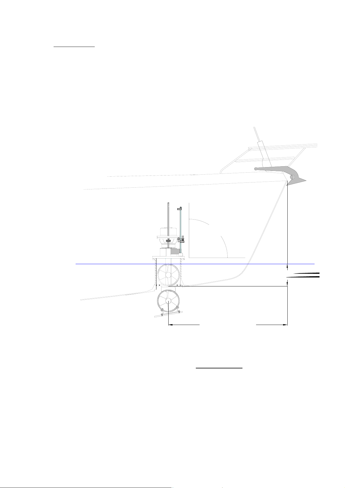
1. POSITIONING
Consider the following, when determining the position of the thruster unit in order to
ensure the most efficient operation:
Find the point the farthest forward (or aft), while keeping in mind the space available,
given the vessel’s fixtures, space and shape and while respecting the minimum
immersion depth of one full turbine diameter (185 mm).
90°
Water Line
As far forward
as possible.
Always check and make sure that there is enough room to allow for the complete
removal of the VIP unit and enough room for the connection of the electric power
cables. These cables must be able to flex freely without kinking
and down.
To install a VIP in the stern, make sure that the turbine flow is clear of all obstacles, or
select the best possible compromise.
when the VIP goes up
3
VIP 250, Hydraulic with Electronic Controller 25/12/2005
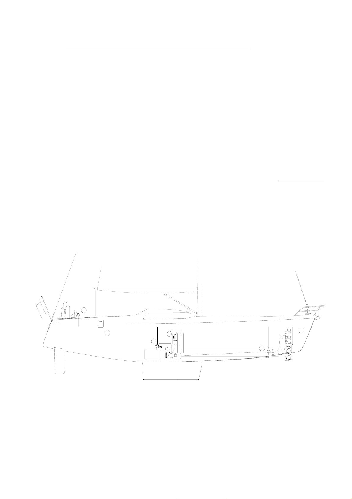
2. DETERMINE THE LOCATION OF THE AUXILIARY EQUIPMENT
The hydraulic directional valve should be located near to the thrusters unit, in a
horizontal position, installed in an accessible and dry place.
The hydraulic oil reservoir must be located above and as near as possible to the
hydraulic pump. The hydraulic oil must gravity feed the pump.
The electropump (if used) must be as NEAR TO ITS BATTERIES AS POSSIBLE, it must have
a reasonable supply of air for ventilation and must be KEPT DRY.
A Max Power main fuse, of the correct size
(see section 4.3),
must be installed in the
positive supply cable, as close as possible to the electropump battery bank and it must
be easily accessible and clearly marked.
A manual battery isolator, of the correct size, should be installed in the positive supply
cable, as close as possible to the electropump battery bank and must be easily accessible
and clearly marked
VIP HYDRAULIC
General auxiliary equipment location
Thruster assembly
1
Control box
3
Hydraulic distribution DCV
4
5
3
Control panel
5
Hydraulic oil reservoir with filtration system
6
Electro hydraulic pump EHP
7
Power relay/power fuses
8
6
8
_
+
7
1
4
An electrical battery isolator, as supplied by Max Power, should be installed in the positive
supply cable, as close as possible to the electropump battery bank, in order to benefit
from all automatic safety features of the electronic control system.
The thruster electronic control box should be installed in proximity of the electropump
unit in a completely dry and ventilated area.
The control panel(s) should be installed as desired at the helm station(s) in a protected
and waterproof manner.
4
VIP 250, Hydraulic with Electronic Controller 25/12/2005
3. MECHANICAL INSTALLATION
3.1 MOUNTING BASE INSTALLATION
(Please refer to “Build Drawing” at back of this document
):
MAX POWER can supply, either a G.R.P. mounting base or a 5086 aluminium alloy-
mounting flange. These bases save considerable shipyard time while assuring solid and
precise installation.
a) For GRP hulls the mounting base should be laminated into the hull. The base
supplied is only to help give the initial form; its strength will come from additional
lamination (inside and out) added when laminating the hull.
b) For alloy hulls the mounting flange should be welded onto the base, which has
been fabricated into the hull.
The method and materials used for making the mounting base must be adapted to the
particular hull material (laminated wood, GRP, sandwich, aluminium, or steel). Naval
Architects, Classification Societies or specialised firms should be consulted.
The thruster(s) mechanical stresses are spread over the hull by the mounting base. Its
installation reinforces the hull, if well calculated, but it might be necessary to attach it by
gussets to frames and stringers.
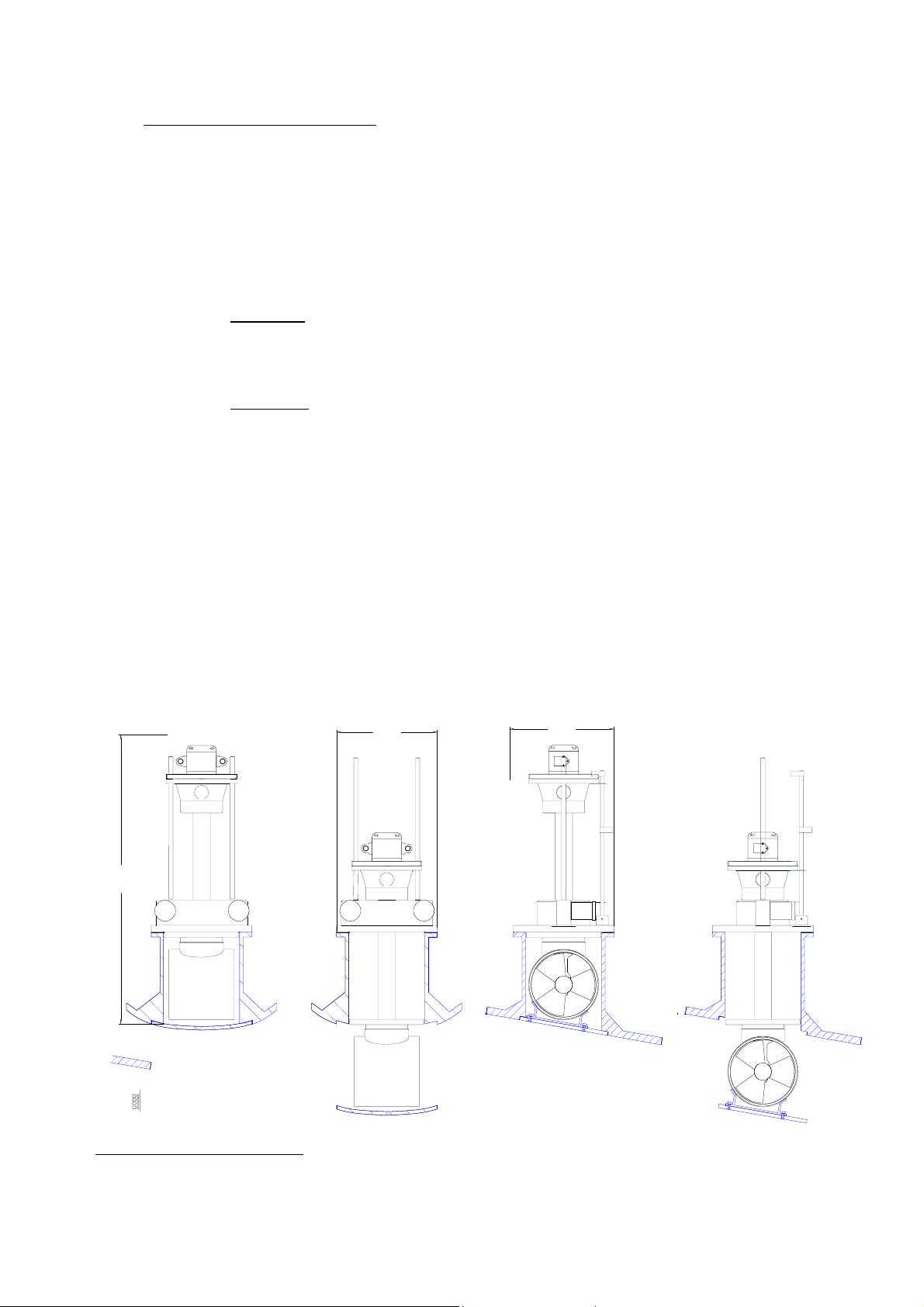
When setting the mounting base, do not forget to take into account the overall
dimensions of the VIP.
370
370
950
Hull parts
Thruster parts
Total Unit Weight = 37kg
5
VIP 250, Hydraulic with Electronic Controller 25/12/2005
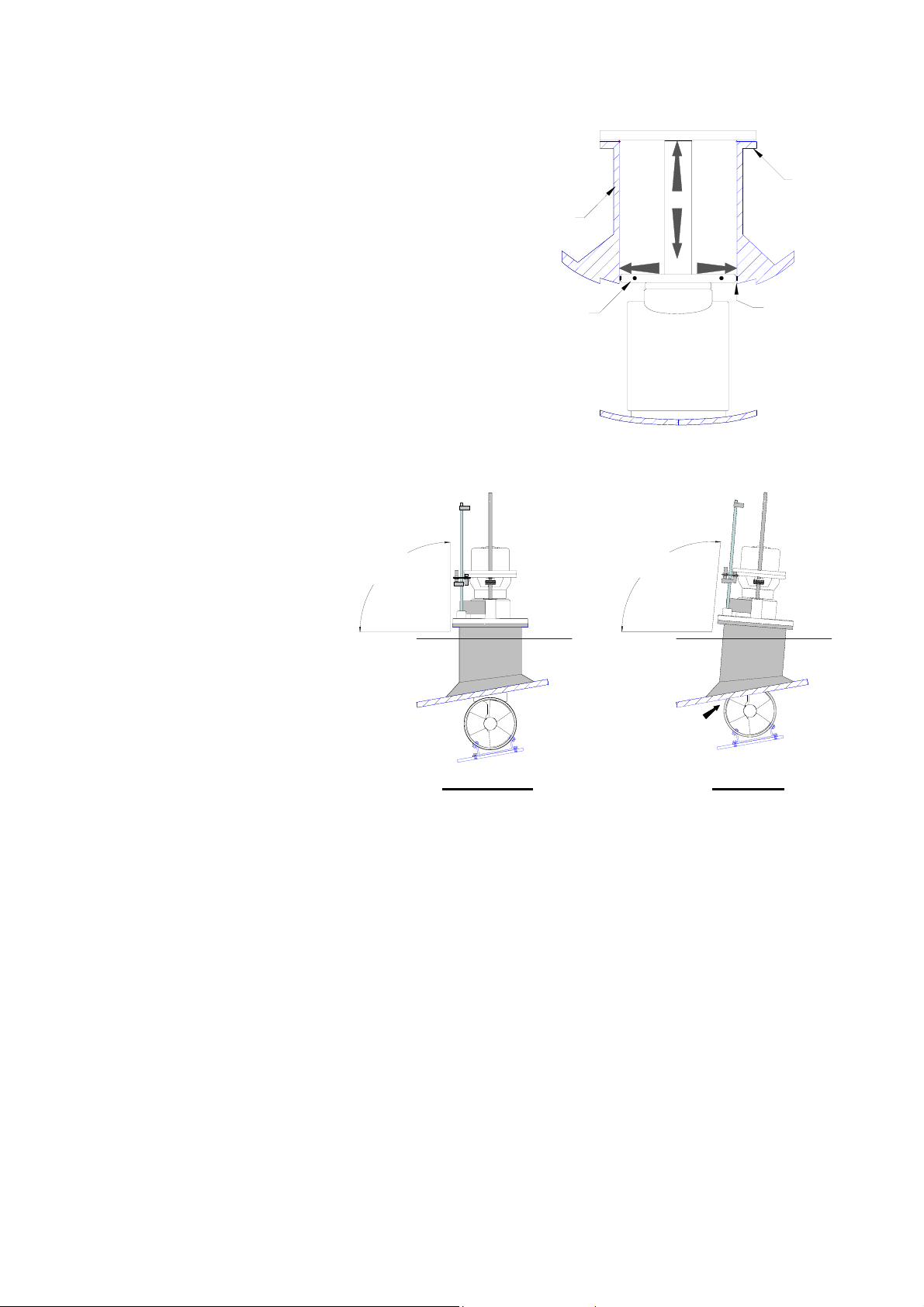
A
The VIP pushes its thrust plate sideways
against the inside of the mounting base
when running. This means that one must
totally lower the unit and check the
following:
(a) That the VIP’s thrust plate is free to
move up and down.
(b)
nd also that there is no more than
2mm horizontal movement
between the thrust plate and the
mounting base, especially when
fully down.
The mounting base
flange should be parallel
to the waterline.
90°
In other words the
thruster unit must be
installed vertical with its
turbine totally clear of
the hull in the down
position.
Mounting
Base
Thrust Plate
Water
Line
( a )
Not 90°
Mounting
Base
Flange
( b )
< 2 mm
Water
Line
CORRECT
WRONG
Before fixing the thruster unit onto the mounting base flange it is important to ensure
that the top surface of the mounting base flange is perfectly flat in order to accept the
« O » ring seal of the VIP base flange in order to ensure perfect water tightness.
The bolts fixing the VIP onto the mounting flange must be inserted from top to bottom.
Provide sufficient access underneath the flange to allow for tightening the nuts. If the
access is not possible, provide a special mounting flange with metric studs or tapped
holes.
6

VIP 250, Hydraulic with Electronic Controller 25/12/2005
3.2 CONSTRUCTION OF HULL OPENING & CLOSING PLATE:
The opening made for the thruster in the hull is closed by a plate, which can be made from
the cutout hull section, or specially fabricated.
a) The closing plate should fit into a 15 – 20
mm wide rebate in the hull when in the
raised position. This is to transfer all the seas
slamming forces to the hull and not to the
electric rams!
b) The closing plate must be securely fixed to
Hull
Hull
Closing
Plate
15 - 20 mm
wide rebate
in hull.
the supplied adjustable aluminium-mounting
fitting.
c) A gasket must be installed in the hulls
rebate. This gasket can be made either from
neoprene or moulded in «SIKAFLEX» (or
( c )
( b )
similar product). Precautions should be taken
to ensure that the gasket does not stick to
the closing plate. The plate must rest evenly
on this gasket when the thruster is closed.
( a )
To prevent marine growth inside the turbine enclosure, it is essential that once the unit is
raised, no light be allowed to enter.
On an excellent installation the enclosure may even be watertight. If this is achieved anode
life will be greatly increased (No circulating water, no oxygen and no corrosion!).
The use of antifouling or other paints on the thruster unit is not necessary if the closing
plate closes properly onto its seal.
However, if painted, never use copper based paints and do not paint the vertical
column of the unit.
3.3 FINAL FITTING OF THE THRUSTER UNIT TO THE MOUNTING BASE:
Final installation of the thruster unit onto the mounting base must be made after
thoroughly cleaning and then liberally coating both joint surfaces (thruster base flange and
mounting base flange) with good quality marine grease. This is so that the «O» ring seal is
compressed flat, evenly, smoothly and squarely when the bolts are tightened.
Under no circumstances should the thruster be glued or bedded down with a marine type
mastic/glue such as Sikaflex or other similar product(s).
The flange bolts should be tightened sequentially and in successive passes until the two
surfaces touch.
7
VIP 250, Hydraulic with Electronic Controller 25/12/2005
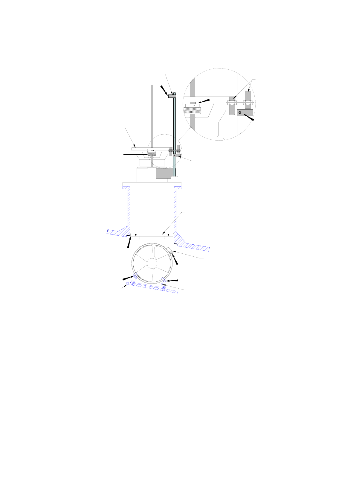
3.4 FINAL ADJUSTMENT OF THE CLOSING PLATE:
Once the thruster is permanently bolted onto the mounting base, reinstall the closing plate
to do the final adjustments.
"Up" Position Detector
Motor Support
Adjustment Nuts
( b )
Proximity
Switches
( d )
( c )
"Down"
Position
Detector
Thrust Plate
( e )
Hose Clamp
( a )
Hull
Closing
Plate
( f )
( f )
Alloy Plate Bracket
a) Lower and raise the turbine to determine correct position of the hull closing plate so
that it fits evenly and squarely in the rebate in the hull, then tighten the hose clamps
(delivered with unit). The closing plate must rest evenly on its gasket, with pressure so
that no upwards movement of the plate is possible even in heavy sea conditions when
the hull is subjected to slamming forces.
b) Once the hull closing plate adjustment has been completed, adjust the "up" position
detector and tighten its grub screw with a 2.5 mm Allen key.
This should be done with
the unit fully retracted.
c) Note that the down position detector is pre-adjusted (before leaving the factory) and
should not be touched.
d) If re-adjustment is necessary, care should be taken to re-adjust the detector so that
adjustment nuts do not touch the motor support when fully down and that the
detector grub screw (2.5mm Allen key screw) is tightened down after re-adjustment.
8
VIP 250, Hydraulic with Electronic Controller 25/12/2005
e) The thrust plate should not protrude from the mounting base, since it absorbs the
horizontal stresses when thrusting or manoeuvring. If protruding, adjust the down
position detector as described above.
f) When finished with the final adjustments, fix the alloy plate bracket by bolting through
the GRP turbine in addition to the cable clamps.
IMPORTANT: Please keep in mind that the power supply to up/down motors is not
automatically interrupted if the proximity switches do not detect the position detectors. Care
must therefore be taken to remove ones finger from up or down button as soon as the unit
blocks in fully up or fully down position when closing plate adjustments are done and if
position detectors are not adjusted yet.
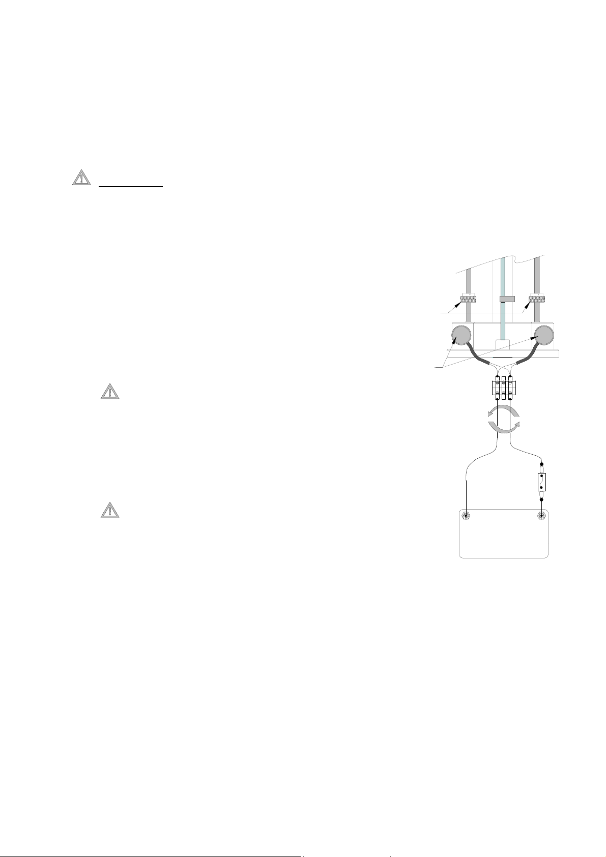
Installation Advice: In order to make sure that VIP is
raising and lowering smoothly and when closing plate
adjustments are made, one can do the following:
a) Connect 12V/24V directly to the two up/down
Adjusment
Nuts
( b )
motors (depending on up / down motor voltage)
and simply reverse the polarity to change
direction (raise/lower).
Note. The Drive Screws rotate in opposite
directions, therefore the motors must turn in
opposite directions. If a supply is going to be
Up/Down
Motors
-
+
+
-
directly fed to the up / down motors for ease of
installation, then the positive of one motor
should be connected to the negative of the other
motor and vice versa.
Fuse
( 10 A )
It is important to install a 10A fuse in the
positive cable and to keep in mind that wires
need to be disconnected as soon as the up or
down position is reached or as soon as the unit
If the unit blocks before reaching the up/down position or if the unit
vibrates excessively when going up/down one needs to adjust the two
adjustment nuts to ensure the unit is completely vertical to its base.
-
+
12 V / 24V
Depending on
motor voltage.
( b )
( a )
9

VIP 250, Hydraulic with Electronic Controller 25/12/2005
4. HYDRAULIC POWER SYSTEM INSTALLATION
The hydraulic power equipment, such as the oil reservoir/filter, pump and
directional control valve, should be installed in compliance with the usual rules of
accessibility to enable periodic checks and maintenance.
Remember that:
(1) The oil tank must gravity feed to the pump.
(2) The directional control valve must be fitted as close as is convenient to the
thruster unit, in order to verify the hydraulic pressure gauge.
All hydraulic high pressure power circuit piping must comply with high pressure
standards (Flexible hose – HP SAE 100 R8 or R9), and have a diameter at least
equal to that recommended in order to reduce head loss especially when the
installation’s layout requires long hose lines. These hoses or pipes should
preferably have 1/2″ interior diameter.
No hose, pipe or fitting in the power circuit should ever have an interior diameter
less than 3/8″.
All power circuit piping must have a service pressure rating of at least 250 bar,
with a rupture pressure rating of 500 bar.
Fittings must be of good quality and crimped as per manufacturers instructions,
and pressure tested to at least 400 bar.
All pipes and hoses must be absolutely clean when connected to the circuit!
The pump intake hose line (from the reservoir) must be of a quality that is not
subjected to pinching or crimping due either to vacuum, to an excessively small
radius of curvature, or to variations of temperature.
This hose or pipe should always be shorter
than 2 meters and preferably have 1″
interior diameter but not less than 3/4″ID
MAX POWER recommends the use of ISO GRADE 15 to 32 hydraulic oils for the hydraulic
power circuit. Max Power has already used this oil during the run in tests and consequently the
Thrusters motor and piping are already filled with such.
CAUTION
: Biodegradable and mineral (commonly used) oils are non-compatible and should
not be mixed or used together. Mixing them will deteriorate certain hydraulic elements. If you
intend to use biodegradable oil, thoroughly flush the existing mineral oil from the unit first with
the appropriate oil.
10
 Loading...