

MAX power MPOP5720/US, MPOP5721/US User Manual

REMOTE CONTROL
INSTALLATION OPERATION MAINTENANCE
Via Philips 5, 20900 Monza (MI), Italy
Tel: +39 039 2001973-936 - Fax: +39 039 2004299
Email: contact@max-power.com - www.max-power.com
USER MANUAL
THIS MANUAL MUST BE KEPT ON BOARD AT ALL TIMES


Contents
Section Title Page
1 DESCRIPTION 4
2 TECHNICAL SPECIFICATIONS 4
3 PRODUCT REFERENCES 5
4 PACKAGING CONTENTS 5
5 GENERAL DIMENSIONS 6
6 INSTALLATION AND CONNECTIONS 6
7 SET UP 7
8 RESETTING 8
9 ADDING ADDITIONAL TRANSMITTERS AND RECEIVERS 8
10 EXAMPLES OF USE 9
11 REPLACING BATTERIES 9
12 TROUBLE SHOOTING 10
13 WORLDWIDE DISTRIBUTION 10
14 WARRANTY 11
15 ELECTRICAL WIRING CONNECTION 12
It is strongly advised that only qualied marine electricians should install this equipment. For any boat requiring ocial
classication, bodies of approval should also be consulted at the earliest opportunity. In any case, all other bodies,
governmental or otherwise, should be contacted to ensure conformity with legal regulations relating to the boat in
question.
IT IS ESSENTIAL TO READ THE FOLLOWING MANUAL CAREFULLY
BEFORE INSTALLING THIS EQUIPMENT
3
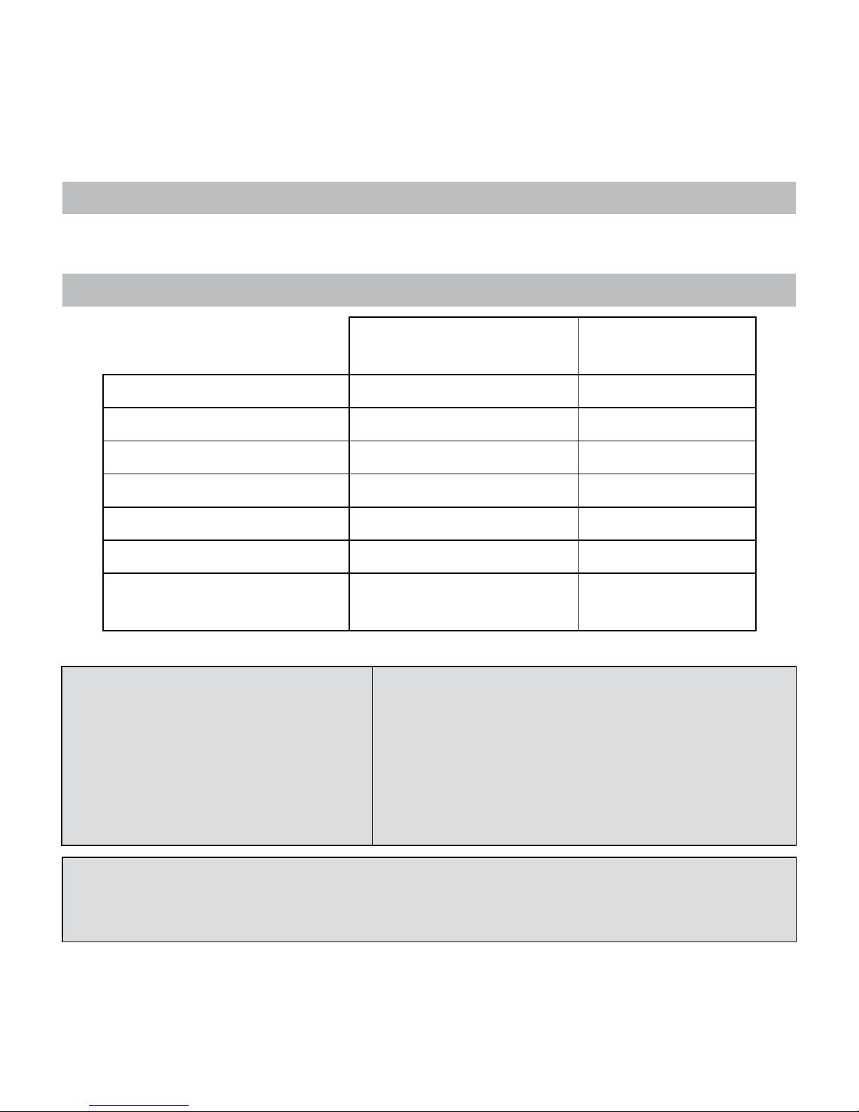
TRANSMITTER
MPOP5720/US
RECEIVER
MPOP5721/US
Power supply 2 lithium batteries 3V (CR2430) 12 to 24V DC
Power consumption in standby 0A 22mA @ 12V DC
Power consumption when in use 50 mA @ 6V DC max 110 mA @ 12V DC max
Operating temperature -15°C / +55°C -15°C / +55°C
Dimensions (mm) 114 x 60 x 22 125 x 78 x 21
Weight (g) 80g 110g
Frequency (MHz)
868 (EU regulation)
915 (US regulation)
868 (EU regulation)
915 (US regulation)
R & TTE Directive
EN 300 220-1 V2.1.1 (2006-04)
EN 300 220-2 V.2.1.1 (2006-04)
EN 300 220-2 V2.1.2,
EN 301 489-3,
ETSI EN 301 489-3 V1.4.1 (02)
EN 60945
EN 60945 (02)
EN 60950-1: 2006;
CEI 60950-1: 2005
FCC ID: W6Z (Transmitter)
IC: 8220A (Transmitter)
IC: 8220A (Receiver)
1- DESCRIPTION
2- TECHNICAL SPECIFICATIONS
The Max Power radio remote control is designed to work with Max Power’s entire range of tunnel and retractable
thrusters. The remote control can also be used to operate any other onboard equipment for which it may be useful.
This device complies with part 15 of the FCC rules. Operation is subject to the following two conditions (1) This device may not
cause harmful interference and (2) this device must accept any interference received including interference that may cause
undesired operation.
This product is in compliance with the following regulations:
4
868 MHz
(EU regulation)
915 MHz
(US regulation)
312973
312974
312971
312972
312969
312970
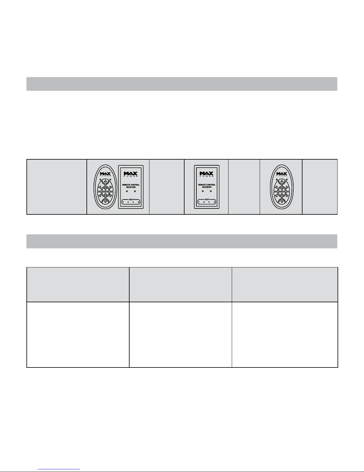
3- PRODUCT REFERENCES
4- PACKAGING CONTENTS
The remote control is available as a kit including both the transmitter and the receiver. Additional receivers and spare
transmitters are also available independently.
EU and US regulations require dierent frequencies. For this reason both the transmitter and the receiver are available
in 2 dierent frequencies.
• Each transmitter includes its batteries (2 x CR2430)
• Each receiver includes its connectors
The Remote Control is delivered with:
312973 (EU)
312974 (US)
KIT REMOTE CONTROL
312971 (EU)
312972 (US)
312969 (EU)
312970 (US)
9 1 transmitter
9 1 receiver
9 2 connectors
9 2 brackets + 2 screws
9 1 lanyard
9 1 user manual
9 1 receiver
9 2 connectors
9 2 brackets + 2 screws
9 1 user manual
9 1 transmitter
9 1 lanyard
9 1 user manual
5
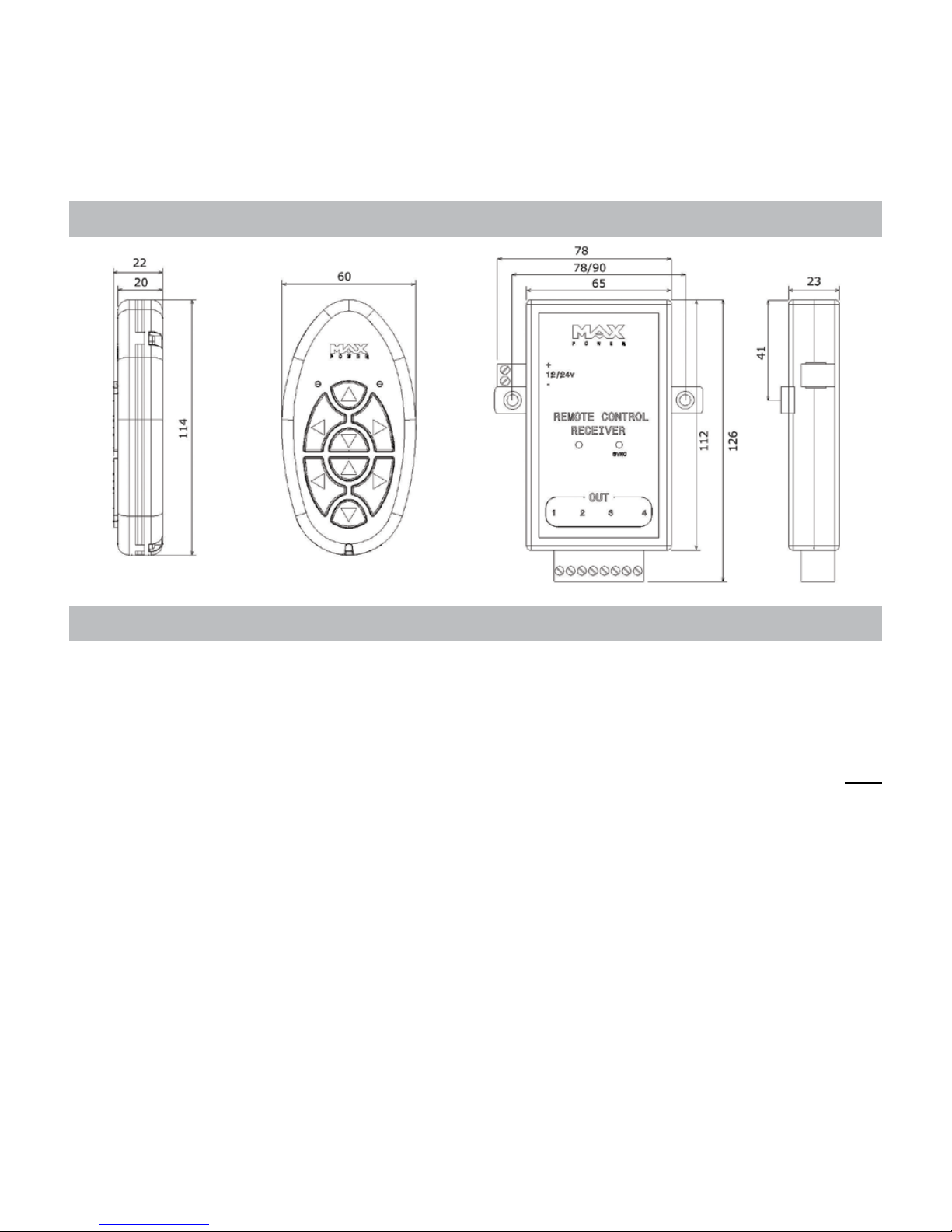
5- GENERAL DIMENSIONS
6- INSTALLATION AND CONNECTIONS
1. Turn OFF the power supply to the thruster or the equipment being connected
2. Fit the receiver in a dry and accessible area (preferably not in the bilge). If necessary, use the 2 brackets supplied by
removing the 2 screws on the back of the receiver and replacing them with the 2 other screws supplied (M2.5 x 16).
For a thruster, an ideal location is behind one of the thruster control panels.
3. Connect the receiver to the power supply (12 or 24V DC)
4. CAUTION: ENSURE THE POLARITIES ARE RESPECTED. Reversing the polarity of the receiver WILL
irreversibly damage the receiver’s circuits.
5. Protect the positive supply cable of the receiver by means of a 1A fuse.
6. The receiver already has an integrated protection.
7. Connect the 4 outputs of the receiver (1, 2, 3 & 4) to the equipment that is to be operated. In the case of a bow
thruster or windlass, see the annexed diagrams for precise instructions.
8. NB: The outputs (1, 2, 3 & 4) are isolated volt free contacts with a load switching capacity of up to 24V and 5A
9. Follow the set up instructions (cf. chapter 7)
CAUTION:
Fit the receiver as far as possible from large metallic objects, electric motors or high current cables.
Please connect the radio receiver’s power supply to the yacht’s main service battery bank.
The battery bank powering the receiver must be suciently charged (refer to the battery supplier’s recommendations).
All dimensions are in mm
6
 Loading...