

Max Power MPOP5720 Users Manual
Manual Remote Control October 2009
MANUEL UTILISATEUR Français
Page
8
USER MANUAL
English
Page 2
REMOTE CONTROL
INSTALLATION OPERATION MAINTENANCE
THIS MANUAL MUST BE KEPT ON BOARD AT ALL TIMES
CE MANUEL DOIT ETRE CONSERVE A BORD EN TOUTE CIRCONSTANCES
Max Power S.A.S, 10 allée François Coli, 06210 MANDELIEU, FRANCE
Tél. +33 492 19 60 60 - Fax + 33 492 19 60 61
Email : mp@max-power.com - www.max-power.com

Manual Remote Control October 2009
English
Contents
Section Title Page
1 DESCRIPTION
2 TECHNICAL SPECIFICATIONS
3 PRODUCT REFERENCES
4 PACKAGING CONTENTS
5 GENERAL DIMENSIONS
6 INSTALLATION AND CONNECTIONS
7 SET UP
8 RESETTING
9 ADDING ADDITIONAL TRANSMITTERS AND RECEIVERS
10 EXAMPLES OF USE
3
3
3
4
4
4
5
5
6
6
11 REPLACING BATTERIES
12 TROUBLE SHOOTING
13 WORLDWIDE DISTRIBUTION
14 WARRANTY
12 ELECTRICAL WIRING CONNECTION
6
7
7
7
14
It is strongly advised that only qualified marine electricians should install this
equipment. For any boat requiring official classification, bodies of approval should also be
consulted at the earliest opportunity. In any case, all other bodies, governmental or
otherwise, should be contacted to ensure conformity with legal regulations relating to the
boat in question.
IT IS ESSENTIAL TO READ THE FOLLOWING MANUAL CAREFULLY
BEFORE INSTALLING THIS EQUIPMENT
www.max-power.com 2
Manual Remote Control October 2009
1- DESCRIPTION
The Max Power radio remote control is designed to work with Max Power’s entire range of tunnel and
retractable thrusters. The remote control can also be used to operate any other onboard equipment for
which it may be useful.
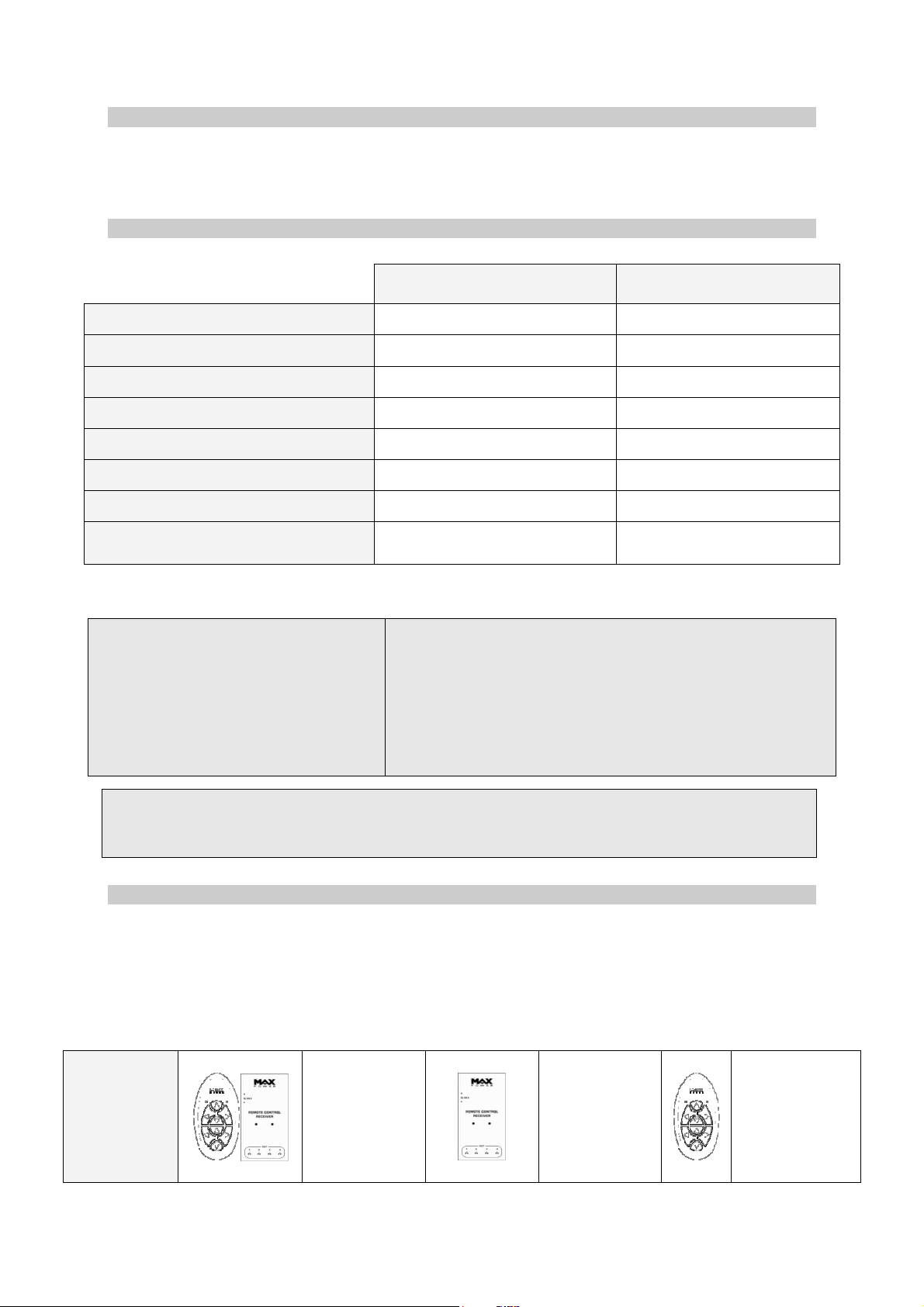
2- TECHNICAL SPECIFICATIONS
TRANSMITTER
MPOP5720/US
RECEIVER
MPOP5721/US
Power supply
Power consumption in standby
Power consumption when in use
Operating temperature
Dimensions (mm)
Weight (g)
Waterproof to
Frequency (MHz)
2 lithium batteries 3V (CR2430) 12 to 24V DC
0 A 22mA @ 12V DC
50 mA @ 6V DC max 110 mA @ 12V DC max
-15°C / +55°C -15°C / +55°C
114 x 60 x 22 125 x 78 x 21
80g 110g
IP 67 --
868 (EU regulation)
915 (US regulation)
868 (EU regulation)
915 (US regulation)
This product is in compliance with the following regulations:
R & TTE Directive
EN 300 220-1 V2.1.1 (2006-04)
EN 300 220-2 V.2.1.1 (2006-04)
EN 300 220-2 V2.1.2,
EN 301 489-3,
ETSI EN 301 489-3 V1.4.1 (02)
EN 60945
EN 60945 (02)
EN 60950-1: 2006;
CEI 60950-1: 2005
FCC ID: W6Z–MPOP5720 (Transmitter)
IC: 8220A–MPOP5720 (Transmitter)
IC: 8220A–MPOP5721 (Receiver)
This device complies with part 15 of the FCC rules. Operation is subject to the following two
conditions (1) This device may not cause harmful interference and (2) this device must accept
any interference received including interference that may cause undesired operation
3- PRODUCT REFERENCES
The remote control is available as a kit including both the transmitter and the receiver. Additional
receivers and spare transmitters are also available independently.
EU and US regulations require different frequencies. For this reason both the transmitter and the
receiver are available in 2 different frequencies.
Each transmitter includes its batteries (2 x CR2430)
Each receiver includes its connectors
868 MHz
(EU regulation)
915 MHz
(US regulation)
www.max-power.com 3
MPOP5722/EU
MPOP5722/US MPOP5721/US
MPOP5721/EU
MPOP5720/EU
MPOP5720/US
Manual Remote Control October 2009
4- PACKAGING CONTENTS
The Remote Control is delivered with:
MPOP5722/EU
MPOP5722/US
KIT REMOTE CONTROL
1 transmitter
1 receiver
2 connectors
2 brackets + 2 screws
1 lanyard
1 user manual
1 receiver
2 connectors
2 brackets + 2 screws
1 user manual
MPOP5721/EU
MPOP5721/US
RECEIVER
MPOP5720/EU
MPOP5720/US
TRANSMITTER
1 transmitter
1 lanyard
1 user manual
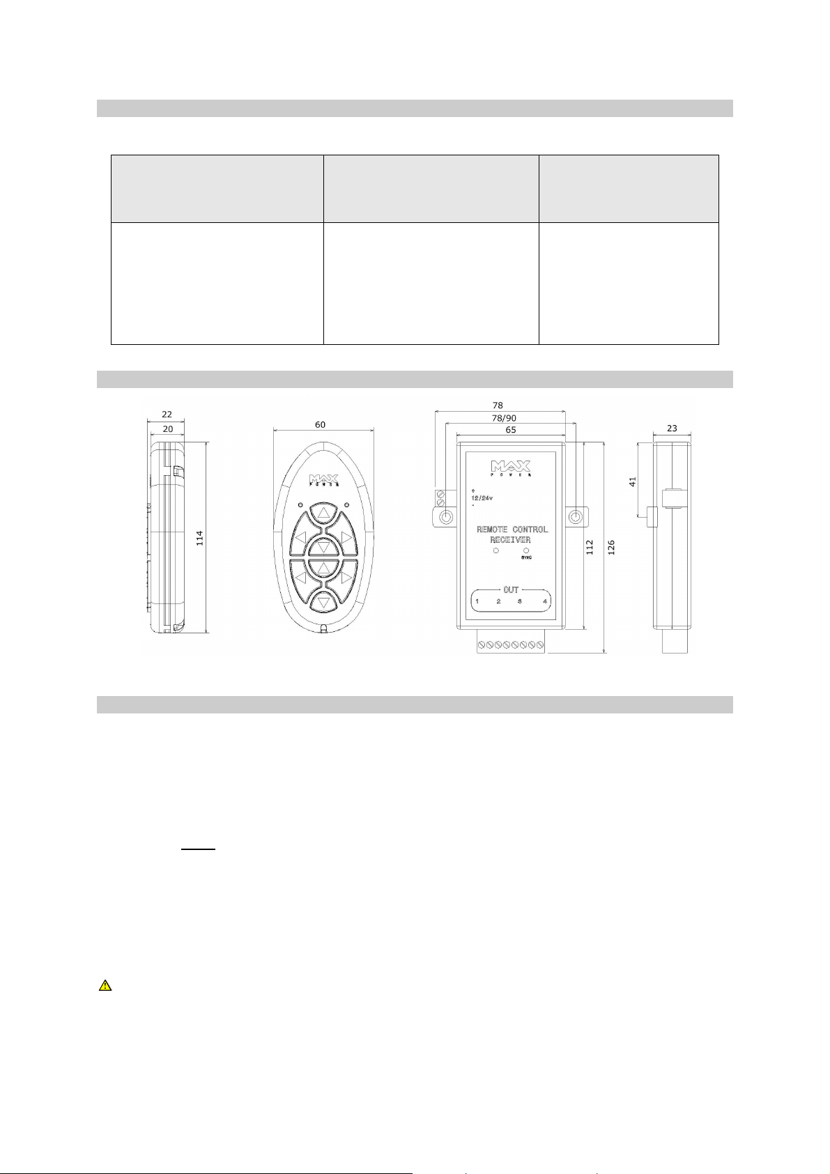
5- GENERAL DIMENSIONS
All dimensions are in mm
6- INSTALLATION AND CONNECTIONS
1- Turn OFF the power supply to the thruster or the equipment being connected
2- Fit the receiver in a dry and accessible area (preferably not in the bilge). If necessary, use the 2
brackets supplied by removing the 2 screws on the back of the receiver and replacing them with
the 2 other screws supplied (M2.5 x 16). For a thruster, an ideal location is behind one of the
thruster control panels.
3- Connect the receiver to the power supply (12 or 24V DC)
CAUTION: ENSURE THE POLARITIES ARE RESPECTED. Reversing the polarity of the
receiver WILL
Protect the positive supply cable of the receiver by means of a 1A fuse.
The receiver already has an integrated protection.
4- Connect the 4 outputs of the receiver (1, 2, 3 & 4) to the equipment that is to be operated. In the
case of a bow thruster or windlass, see the annexed diagrams for precise instructions.
NB: The outputs (1, 2, 3 & 4) are isolated volt free contacts with a load switching capacity
of up to 24V and 5A
5- Follow the set up instructions (cf. chapter 7)
CAUTION:
Fit the receiver as far as possible from large metallic objects, electric motors or high current
cables.
Please connect the radio receiver’s power supply to the yacht’s main service battery bank.
The battery bank powering the receiver must be sufficiently charged (refer to the battery supplier’s
recommendations).
www.max-power.com 4
irreversibly damage the receiver’s circuits.
Manual Remote Control October 2009
Red
Brown
Blue
Red
Brown
Blue
Red
B
rown
Blue
Red
Brown
Blue
Red
Brown
Blue
Red
Brown
Blue
Red
Brown
Blue
Red
Brown
Blue
Red
Brown
Blue
Red
Brown
Blue
1 2 3
4 5
NOTE
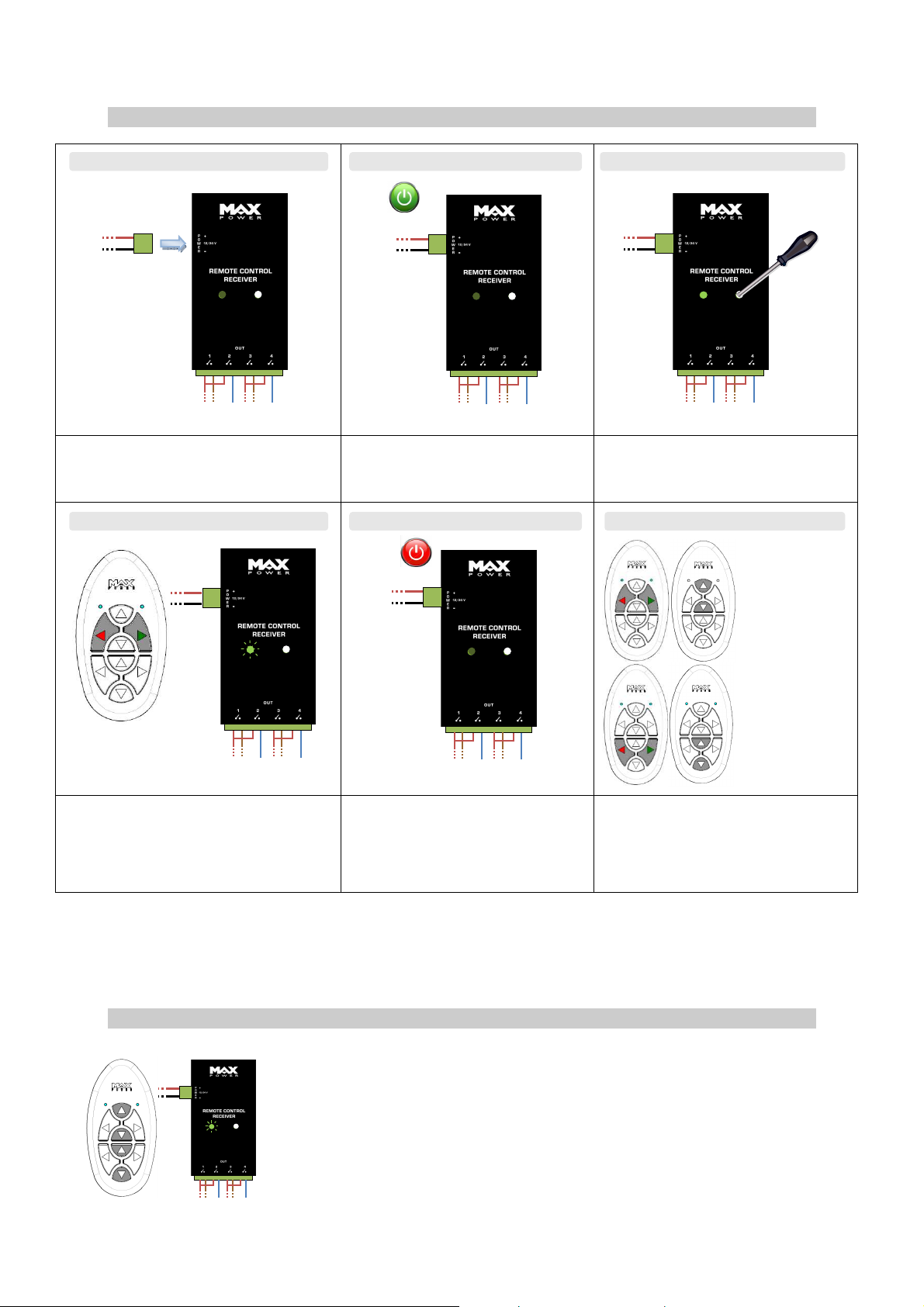
7- SET-UP
ON
Connect the receiver to the power supply
12/24V
*
To activate 2 commands simultaneously
press the 2 buttons* to be activated
The LED will flash.
These commands are now activated
and paired to outputs 1 & 2
Note: Each receiver can handle a maximum of 4 channels: 2 sets of 2 buttons corresponding to
receiver outputs (1, 2, 3 and 4).
Should the full 8 channels of the transmitter be required, a second receiver is needed:
MPOP5721/EU (EU regulation) or MPOP5721/US (US regulation)
Turn the power supply ON
The LED flashes once
OFF
Turn the receiver OFF (for 5 seconds)
Gently press the SYNC button (just
once) using a small screwdriver
The LED lights up
Authorised
*
combinations
To activate other commands return to
step 2
Outputs will be activated in their
numerical order in pairs.
8- RESETTING
To reset a receiver, gently press the SYNC button using a small screwdriver
The Led lights up.
Press the 4 up-down buttons simultaneously
The LED will flash.
The receiver’s memory has been cleared.
Turn the receiver’s power supply OFF, wait 5 seconds and then return to
step 2 (cf. Chapter 7 Set-up)
www.max-power.com 5
 Loading...