

MAX Power HYD325 User Manual

MANUAL SUPER POWER Series 325 HYD Model 325 01/05/2004
Hydraulic Tunnel Thruster
Series 325HYD
Model 325
With Electronic Controller
INSTALLATION OPERATION MAINTENANCE
Serial N° : ----------------------------------------------------
Date of Installation : ----------------------------------------
IT IS IMPORTANT TO KEEP THIS MANUAL ON BOARD!
Technology center – 10 allée François Coli – F 06210 CANNES-MANDELIEU FRANCE.
Tél. +33 (0)492 19 60 60 Fax + 33 (0)492 19 60 61 www.max-power.com e-mail : mp@max-power.com
0

MANUAL SUPER POWER Series 325 HYD Model 325 01/05/2004
To ensure a proper installation, correct usage and long-lasting enjoyment of this
equipment, please take time to read this manual thoroughly.
Table of Contents
Number Description Page
1 General Installation Guidelines 2
2 Tunnel 2-3
3 Propeller Drive Leg & Motor Support 3
4 The Hydraulic Motor and its Adapter 4
5 Propellers 4
6 Protection Grill 4
7 Hydraulic General Remarks 4-5
8 Hydraulic Specifications 5
9 Hydraulic Custom Pack 6
10 Maintenance 7
11 Notes 8
12 Spare Parts List 9
13 Spare Part Diagram 10
14 Control System Connections: Electro-Hydraulic Pump 11
15 Control System Connections: Motor with Clutched PTO 12
16 Super Power Hydraulic Diagram 13
17 Positioning and Measurements 14
18 Warranty Procedures 15-16
19 List of Distributors 17-18
20 Warranty Document (to be returned) 19
Your thruster is a high quality technical product and should be treated as such. The employment
of qualified marine personnel, with experience in bow thruster installation, is strongly advised.
Where possible, the boat manufacturer’s architects, design departments and/or shipyards should
be consulted, prior to installation taking place. For any boat requiring official classification, bodies
of approval should also be consulted at the earliest opportunity. In any case, all other bodies,
governmental or otherwise, should be contacted to ensure conformity with legal regulations
relating to the boat in question.
Your thruster should be delivered with the following parts:
Hydraulic Motor &
Coupling
Propellers (2) Safety Stickers x 2 Manual
Motor Support Controller HYD Drive Leg, Propeller
Pin(s) & Coupling
1
MANUAL SUPER POWER Series 325 HYD Model 325 01/05/2004
1) GENERAL INSTALLATION GUIDLINES
Decide on the best location for the SUPER POWER. (See drawing: “Positioning &
Measurements” at back of manual).
The tunnel must be as low as possible and as far forward as possible.
The propellers must not protrude beyond the hull line.
The ideal position of the tunnel is such that there is at least the depth of one tunnel diameter
from the water line to the top of the fitted tunnel. Decreased performance of the SUPER
POWER due to inadequate immersion depth can be compensated by fitting the tunnel as far
forward as possible (increasing lever arm movement).
The SUPER POWER hydraulic thrusters can be fitted vertically, horizontally or tilting.
IMPORTANT: When using tunnels of different thickness (example: metallic tunnel) it is imperative
that the area between the drive leg/gasket and the motor support, matches the
thickness as indicated in the table on the drawing “Positioning & Measurements” at
back of manual and that the motor support is stable.
If you have less than 8 mm thickness, you will require an extra hard rubber gasket
between the motor support and the tunnel.
2) TUNNEL
When the final tunnel position is determined (and all dimensions have been checked), mark the
centre of the tunnel’s position and drill a Ø 10 mm hole. Make up a metal compass from 8 mm
rod.
Fit compass into the Ø 10 mm holes and trace the form of the tunnel on to the hull (elliptical).
After cutting out the elliptic hole, disc the interior surface of the hull, by approx. 10 to 15 cm
around the holes.
The outside surface of the tunnel is then ready to be fibre-glassed.
Do not
stratify over
this zone
Fit the tunnel and mark the areas to be fibre-glassed. Sand these areas inside and out.
In certain installations it is preferable to drill the position of the thruster support before the
installation of the tunnel.
Refit the tunnel. Apply reinforced fibreglass filler to all areas, taking care that you fill the gap
between hull and tunnel. Stratify with a minimum of 8 coats of material and ISOPHTALIQUE
RESINE alternating with mat and roving.
In inaccessible areas (i.e. under the tunnel), it is possible to simply apply reinforced filler.
2
MANUAL SUPER POWER Series 325 HYD Model 325 01/05/2004
CAUTION: Do not fibre glass the area of the motor support.
It is recommended to lightly sand down the area where the motor support is fitted.
On the outside, when the ISOPHTALIQUE RESIN has set, finish with an application of resin and
material, followed with an additional coat on the hull, in the tunnel area.
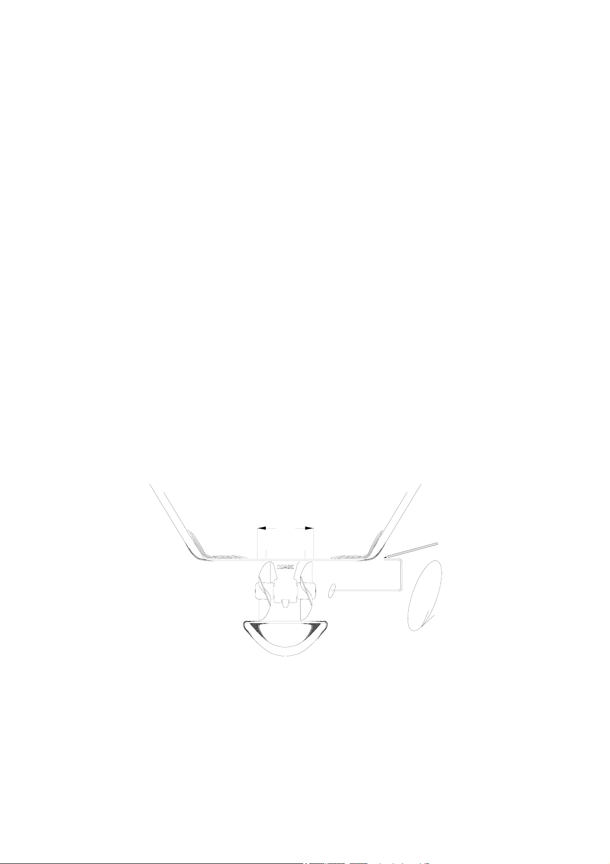
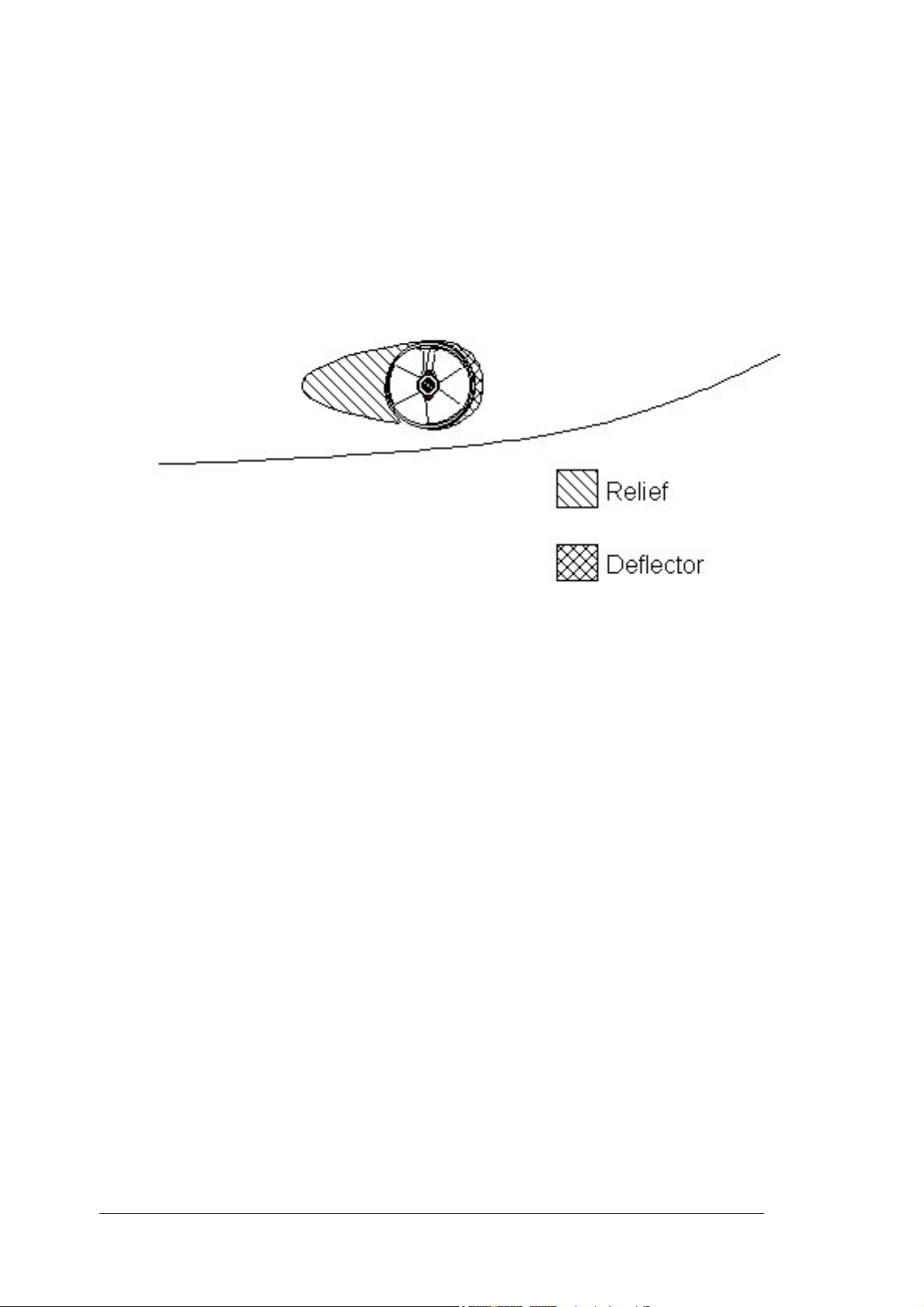
To optimise the flow of water while sailing, deflectors & a relief should be fashioned.
These can be made up with several coats of reinforced filler in order to obtain the required
hydrodynamic lines.
Once all fibreglass work is complete, apply a coat of epoxy or gel-coat to waterproof the entire
area.
3) PROPELLER DRIVE LEG & MOTOR SUPPORT
The leg’s gasket and the motor‘s support can be used to mark up the drilling position, in some
cases it might be easier, to mark out the position, and drill before the stratification of the
tunnel.
Centre and trace the drilling positions for the leg and its support.
Fit the leg along with the gasket, in the tunnel.
Check general positioning of the propellers.
Small pieces of folded cardboard can be used to check the spacing between the propeller tips
and the tunnel is even all round. Slight adjustment to align the leg in its tunnel may be
necessary.
After checks, remove leg etc; remount the assembly, covering the gasket with an oil and salt
water resistant jointing compound. After fitting, remove all excess compound.
The gasket must be between the leg and the tunnel, and not between the motor support and
the tunnel.
Care must be taken at all times when fitting the leg into the motor support to ensure that the
mating components are dirt free and covered with a light film of grease.
IMPORTANT: GRAPHITE GREASE MUST NOT BE USED.
Torque values: screw Ø 12 mm = 80 Nm screw; tighten the two fixing screws alternately.
Once tightened, ensure that the propeller/s turn freely without touching the tunnel.
3

MANUAL SUPER POWER Series 325 HYD Model 325 01/05/2004
4) THE HYDRAULIC MOTOR AND ITS ADAPTER
Do not separate the motor from its adapter.
Insert the lower drive coupling onto the leg drive shaft (lightly grease the shaft before doing
this).
Position the red plastic coupling (piece n° 10 on “Spare Part Diagram”) onto the lower coupling.
Before tightening the 2 x 6 mm Allen fixing screws of the lower coupling, make sure that
coupling is pushed all the way down on drive leg shaft.
Then position the motor and tighten the 4 x 10 mm to 40Nm.
IMPORTANT: Please note that the above coupling might need to be adjusted if any other
tunnel than a Max Power tunnel (thickness 9mm) is used.
The top and bottom coupling pieces should fit tightly together to ensure
maximum gripping between them.
Check that the propellers turn freely and that there is no tight spot. A certain amount of
resistance is normal from the motor. When all is assembled recheck the tightness of all the
motor bolts.
NOTE: The coupling on the motor side is in place when delivered, do not touch this.
5) PROPELLERS
Check the tightness of the oil drain screw (8 mm Allen Key) and the anode (a 10 mm key).
IMPORTANT: To prevent limestone deposits from forming (causing damage to the joints), we
highly recommend applying silicone grease to the shaft and the joints before
assembling the propellers.
Fit the fixing pins and propellers
NOTE: Position the propeller blades opposed and not in line with one another.
Make sure that the propellers turn freely. A certain amount of resistance from the motor is
normal.
Tighten the 24 mm nuts on each propeller to 27 Nm.
Ensure correct protection of hands against the propellers blades.
6) PROTECTION GRILLS
With a shallow tunnel installation, we recommend that you protect the propellers by fitting
horizontal protection grills. These grills will however modify thruster performance.
7) HYDRAULIC (general remarks)
A typical installation of the hydraulic power thruster requires the following elements:
oil reservoir/tank
hydraulic pump
directional control valve
hydraulic motor
circuit piping
oil cooler (depending on type of installation)
4

MANUAL SUPER POWER Series 325 HYD Model 325 01/05/2004
The oil reservoir/tank with return filter and suction strainer should be as close to the pump as
possible and on charge. Meaning that the level of the oil should be above the pump, preferably
with the oil tank above the water line.
For future maintenance, make sure that the return filter is easily accessible. An isolation valve
can be fitted to the suction.
The pump can be driven by either an internal combustion engine (crankshaft pulley or gearbox
PTO) or an electric motor. Depending on the speed and choice of drive, but should always
comply with the rated pressure/flow of the thruster.
For an internal combustion engine with fixed or variable speed, 3 types of pumps can be used,
depending on the unit to be fitted:
Direct PTO:
Fixed flow pump (***)
Variable displacement pump, depending on the model (**) (*)
Fixed flow pump with bypass (**) (*)
PTO with clutch:
Fixed flow pump (**) (*)
Variable displacement pump depending on the model (**) (*)
Fixed flow pump with bypass (**) (*)
On a DC or AC electric motor the following types of pumps can be used:
DC MOTOR:
Fixed flow pump (*)
AC MOTOR:
Fixed flow pump or other (**) (*)
(***) always require oil cooler
(**) require oil cooler when time of operation exceeds 15 minutes,
(*) oil cooler not necessary
Note: The above choices also depend on capacity of the oil tank etc.
The hydraulic directional control valve (DCV) must be equipped with a pressure gauge and
pressure relief valve and should preferably be placed as close as possible to the thruster unit.
The piping can be flexible or a mix of rigid and flexible type and should have crimp-connected
fittings.
The piping should match interior diameters and the service pressure equal or above that which
has been recommended.
The circuits must be as direct as possible and avoid any bends and joints.
The circuits must be clean and closed-off until final connection takes place.
The thruster hoses arriving at the thruster must be of the thermo-plastic non-conductive type.
The hydraulic motor drain line and the return T-line of the DCV should each go separately and
directly, back into the top of the oil tank.
Use synthetic, mineral or vegetable hydraulic oil, to ISO standard 32 to 48
8) HYDRAULIC SPECIFICATIONS
SUPER POWER Series 325HYD Model 325: Flow =38/45 litres/Min; Pressure =210/240 bars
Detailed instructions and diagrams are delivered with each pack, specific to the installation
chosen.
5
 Loading...