

MAX Power CT80-IP User Manual

Manual CT60-IP & CT80-IP April 2009
CT60-IP / CT80-IP
Ignition Protected Thruster
With electronic thruster control
CERTIFIED ISO 8846
INSTALLATION OPERATION MAINTENANCE
Serial No.: ------------------------------------------------------
Installation date: -------------------------------------------------
THIS MANUAL MUST BE KEPT ONBOARD AT ALL TIMES
Max Power S.A.S, 10 allée François Coli, 06210 MANDELIEU, FRANCE
Tél. +33 492 19 60 60 - Fax + 33 492 19 60 61
email : mp@max-power.com - www.max-power.com
www.max-power.com

Manual CT60-IP & CT80-IP April 2009
Section
Title
Page
Contents
1 General installation guidelines 2
2 Tunnel 3
3 Composite motor support and drive leg 4
4 Electric Motor 5
5 Propellers 5
6 Protection grills 5
7 Electrical installation 5
8 Main power fuse 6
9 Batteries 6
10 Electronic control box 7
11 Control panel and thruster control box functions 7
12 Control panel installation 8
13 Tests 8
14 Electrical measurements 9
15 Operation 9
16 Alarms or thermal switch-off 9
17 Safety 10
18 Maintenance 10
19 Electrical installation diagram 11
20 Relay and control box connections diagram 12
21 Spare parts diagram 13
22 Spare parts list 14
23 Troubleshooting guide 15
24 Worldwide distribution network 15
25 Warranty coverage 16
26 Warranty form 18
The use of qualified marine personnel, with experience in bow thruster installation, is
strongly advised. Where possible, the boat manufacturer’s design departments, architects,
and/or shipyards should be consulted, prior to installation taking place. For any boat requiring
official classification, bodies of approval should also be consulted at the earliest opportunity.
In any case, all other bodies, governmental or otherwise, should be contacted to ensure
conformity with legal regulations relating to the boat in question.
IT IS ESSENTIAL TO READ THE FOLLOWING MANUAL CAREFULLY
BEFORE INSTALLING THE THRUSTER
WARNING
Under no circumstances should the thruster casing be opened. Opening or modifying the
thruster may result in it no longer being Ignition Protected. In case of a problem please contact
your local Max Power distributor.
NB : The thruster is delivered without accessories (fuse, fuse holder, control panel).
www.max-power.com 1
Manual CT60-IP & CT80-IP April 2009
1. GENERAL INSTALLATION GUIDELINES
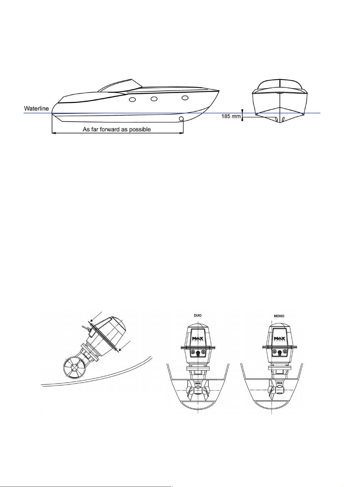
In order to install the thruster in the most efficient position, follow the instructions below:
• The minimum acceptable tunnel position is 139mm below the waterline
• The tunnel is ideally positioned when the distance between the waterline
and the top of the installed tunnel is 185mm
• The tunnel must be installed as far forward as possible
NB: A thruster turbine installed above its ideal position towards its minimum depth will
lead to a progressive loss of performance.
Whether inclined or horizontal, it is recommended to support the electric motor.
The batteries used by the thruster must be charged by both the main engine's alternator
and an appropriate battery charger.
If the thruster is installed using a dedicated battery bank, this must be as close as
possible to the thruster in order to reduce voltage loss in the electric cables.
For the CT60-IP mono, the propeller must be centred in the tunnel.
In the case of the CT80-IP duo, the drive leg must be centered in the tunnel
In no case should the propellers of either models protrude out of the tunnel.
NB: Two metal brackets can be found on the
front and back of the casing which can be
used to hold the thruster in place if
necessary.
www.max-power.com 2
Manual CT60-IP & CT80-IP April 2009
2. TUNNEL
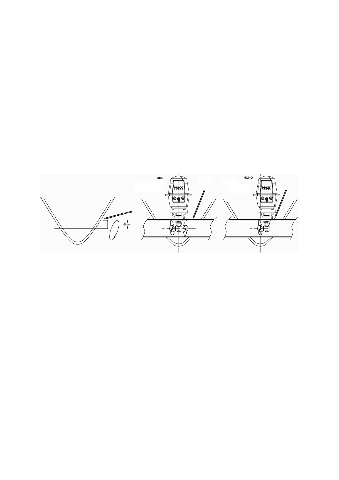
Once the final tunnel position has been determined and all dimensions have been
checked, mark the centre-point of the tunnel on both sides of the hull and drill holes of
8 –10 mm ∅ on either side.
Using a metal rod, construct a compass with a 100mm radius. Insert through the holes
and trace the ellipses, as shown below.
After cutting the holes out following the elliptical guidelines, use an abrasive disc to
prepare the inside and outside surfaces of the hull for laminating (approx. 10 to 15cm
around the holes).
Position the tunnel in the hull, mark the positions of the different components, as well as
the areas that require laminating, then remove the tunnel. It is advisable to drill the tunnel
before laminating it into position. See section 3 "Composite Motor Support and Drive leg"
for more details.
Replace the tunnel. To secure its position apply reinforced fibreglass filler to all areas,
both inside and out, taking care to entirely fill the space between the hull and the tunnel.
Laminate using a minimum of 8 layers of ISOPHTALIC RESIN alternated with mat and
roving.
In difficult to access areas (i.e. under the tunnel), it is possible to only apply reinforced
filler.
Once the filler has set on the outside, finish with a waterproof under coat, followed by
sanding and application of a waterproof finish coat.
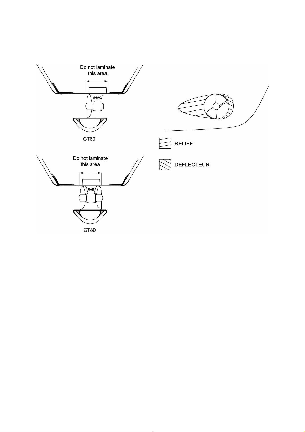
In order to optimise the flow of water whilst sailing, and to avoid turbulence due to the
tunnel, leave 1 to 4 cm of Finish these with several coats of reinforced filler in order to
obtain the required hydrodynamic lines.
Once all laminating work is complete, apply a watertight barrier.
www.max-power.com 3
Manual CT60-IP & CT80-IP April 2009
DO NOT LAMINATE THE AREA OF THE TUNNEL TO WHICH THE ELECTRICAL MOTOR
SUPPORT WILL BE FIXED.
3. COMPOSITE MOTOR SUPPORT AND DRIVE LEG
For the CT60-IP (Mono):
The propeller must be at the center of the tunnel. The motor support and the drive leg will
therefore not be centered in the tunnel.
For the CT80-IP (Duo):
The motor support and the drive leg will be centered in the tunnel.
For both models:
Locate and mark the intended position of the holes for the fixing screws and the leg hub.
You can use the motor support and the leg’s gasket to mark these holes.
In some cases it will be easier to mark and drill these holes BEFORE laminating the
tunnel.
After drilling, use the gasket to verify the holes’ axes and adjust them with a round file
where necessary.
These holes must be completely clean before inserting the screws.
Position the leg, the gasket (between the leg and the tunnel) and the motor support,
and then tighten the the two screws alternatively. Finally, mount the propeller(s) to control
the general alignment.
If the general set-up is correct, remove the propeller(s),the leg and the gasket.
Apply a thin coating of silicon grease or sealing compound to both sides of the gasket
(this must be resistant to hydrocarbons and water). Re-assemble all parts as before,
www.max-power.com 4

Manual CT60-IP & CT80-IP April 2009
positioning and then tightening the two 8mm ∅ screws alternatively using a 5.5mm Allen
key (maximum torque: 25Nm).
Check that the propellers rotate freely, without resistance or friction.
It is imperative that the holes and the screws remain free of sealing compound,
otherwise there is a risk of an incorrect assembly of the parts.
Caution: do not use graphite grease.
NOTE:
The composite drive leg:
• is pre-filled with oil and sealed for life
• does not require anodes
• must not be disasembled, even partially (exclusion waranty)
4. ELECTRIC MOTOR (12 volts)
After having greased the motor shaft and the drive pin, place the motor on its support.
The motor should centre itself and align easily when correctly mounted on its support.
If not, the drive leg, motor support and tunnel are incorrectly assembled. Most likely due
to an uneven surface on the outside radius of the GRP tunnel.
If this is the case dissasemble the motor support / drive leg assembly, sand the tunnel so
as to achieve a smooth exterior radius and repeat the previous steps.
Position the four 8mm ∅ motor support screws, then tighten them alternatively (maximum
torque: 30Nm)
5. PROPELLER(S)
Insert the drive pin and propeller (to be carried out twice for the CT80 duo).
Check that the propeller(s) turn(s) without resistance (a little resistance due to the motor
is normal).
Tighten the fixing screw on the side of the propeller using a 3mm Allen key (maximum
torque: 3 Nm).
Protect your hands during this operation to avoid risks of injuries caused by the edges of
the propeller.
IMPORTANT: to prevent against calcium deposits that damage the seals, we
recommend that you coat the shaft and stainless steel cover with silicon grease.
6. PROTECTION GRILLS
It is possible to install protection grills; however installation of such grills will affect
thruster performance.
7. ELECTRICAL INSTALLATION
CAUTION: an incorrect electrical installation will cause rapid deterioration or even failure
of the thruster. Excessive voltage drop will cause premature wearing of the relays and
brushes. Special attention should be given to the quality, capacity and condition of your
batteries, aswell as cable sections used.
Ensure that all electrical connections are correctly tightened.
www.max-power.com 5
 Loading...