

MAX Power COMPACT User Manual

English Manual: Compact Retract 12/24V, Version 2 14/04/2005
INSTALLATION GUIDE & MAINTENANCE OVERVIEW
MECHANICAL & ELECTRICAL
Serial N°: ----------------------------------------------------
Start up date: -----------------------------------------------
IT IS VERY IMPORTANT TO KEEP THIS MANUAL ON BOARD
TECHNOLOGY CENTER – 10 ALLEE FRANCOIS COLI – F 06210 CANNES-MANDELIEU FRANCE
TEL + 33 492 19 60 60 FAX + 33 492 19 60 61 www.max-power.com
e-mail: mp@max -power.com
1

English Manual: Compact Retract 12/24V, Version 2 14/04/2005
To ensure a proper installation, correct usage and long-lasting enjoyment of this
equipment, please take time to read this manual thoroughly.
TABLE OF CONTENTS
1 Positioning of Unit 4
2 Location of Auxiliary Equipment 4
3 Mechanical installation General 5
3.2 Determining & Marking up Position 6
3.3 Construction of the Hull Opening & Closing Plate 7
3.4 Final Fitting of the Mounting Base to the Hull 8
3.5 Final Fitting of the thruster Unit to the Mounting Base 8
3.6 Fitting of Hull Closing Plate 10
3.7 Final Adjustment and Set-Up of Thruster Unit 11
4 Electircal Installation (General) 11
4.2 Control Panel Installation 11
4.3 Control System 12
4.4 Control Panel & Thruster Control Box fucntions & Modes of Operation 13
a) General Remarks 13
b) Manual Mode 13
c) Automatic set-up Mode 14
d) Normal Operation Mode 14
4.5 Battery Requirements 16
4.6 Power Cable Sections (battery to Relay) 16
4.7 Power Fuse 17
5 Operation Limitations 17
6 Basic Maintenance 18
DIAGRAMS
1) Build Diagram 19
2) Wiring of Control Box 20
3) Control Wiring 21
4) Power Cable Connections 22
Your thruster is a highly technical product and should be treated as such. The employment of a
qualified marine personnel, with bow and stern thruster installation experience is strongly adviced.
Where possible, the boat manufacturers architect, design departments and/or shipyard should be
consulted, prior to installation taking place. For any boat requiring official classification, bodies of
approval should also be consulted at the earliest opportunity.
Your thruster should be delivered with the following parts:
Thruster assembly with integrated
thrusters motor, up / down motor,
motor coupling, leg and propellers
Control Panel (Grey) 25m Control Cable Manual
Plaque for closing
plate (kit)
Directional Relay Box Control Box
2
English Manual: Compact Retract 12/24V, Version 2 14/04/2005
y
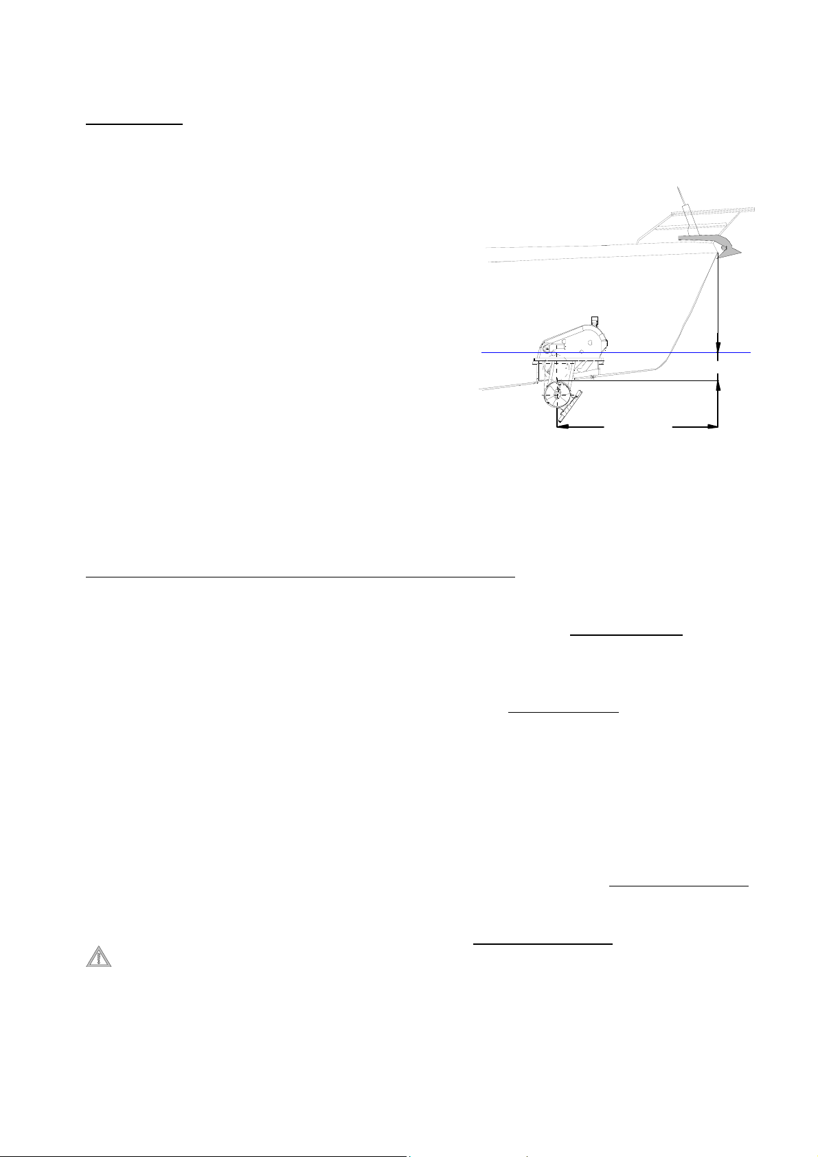
1. POSITIONING
WARNING: Correct positioning is essential for the correct operation of this unit.
Find the point the farthest forward
(or aft), while keeping in mind the
space available, given the vessel’s
fixtures, space and shape ensuring
ou respect the minimum immersion
depth of one full turbine diameter
(185 mm).
Water
Line
Minimum 185 mm
As far forward
as possible
Always check and make sure that there is enough room to allow for the complete removal of
the thruster unit and enough room for the connection of the electric cables.
To install a Compact Retract in the stern, make sure that the turbine flow is clear of all
obstacles, or select the best possible compromise.
2. DETERMINE THE LOCATION OF THE AUXILIARY EQUIPMENT
A power fuse, of the correct size
(see section 4.3),
must be installed in the positive supply cable,
as close as possible to the thruster’s battery bank and it must be easily accessible and clearly
marked.
A manual battery isolator, of the correct size, should be installed in the positive supply cable, as
close as possible to the thruster’s battery bank and must be easily accessible and clearly marked
An electrical battery isolator, as supplied by Max Power, should be installed in the positive supply
cable, as close as possible to the thruster’s battery bank, in order to benefit from all automatic
safety features of the electronic control system.
The thruster electronic control box should be installed in proximity of the thruster unit in a
completely dry and ventilated area.
The thruster relay box should be installed in proximity of the thruster unit, above the waterline in
a completely dry and ventilated area.
The thruster motor terminal busbar should be installed above the waterline.
Care should be taken to securely fix the opening of the black rubber hose, containing power
cables, above the vessel’s waterline.
The control panel(s) should be installed as desired at the helm station(s) in a protected and
waterproof manner.
3
English Manual: Compact Retract 12/24V, Version 2 14/04/2005
3. MECHANICAL INSTALLATION
(Please refer to “Build Drawing” at back of this document, see pg 18
):
3.1 GENERAL
MAX POWER can supply, either a steel reinforced G.R.P. mounting base or a 5086 aluminium
alloy-mounting flange. These bases save considerable shipyard time while assuring solid and
precise installation.
a) For GRP hulls the mounting base should be laminated into the hull. The base supplied is
only to help give the initial form; its strength will come from additional lamination (inside
and out) added when laminating the hull.
b) For alloy hulls the mounting flange should be welded onto the base, which has been
fabricated into the hull.
The method and materials used for making the mounting base must be adapted to the particular
hull material (laminated wood, GRP, sandwich, aluminium, or steel). Naval Architects,
Classification Societies or specialised firms should be consulted.
The thruster(s) mechanical stresses are spread over the hull by the mounting base. Its installation
reinforces the hull, if well calculated, but it might be necessary to attach it by gussets to frames
and stringers.
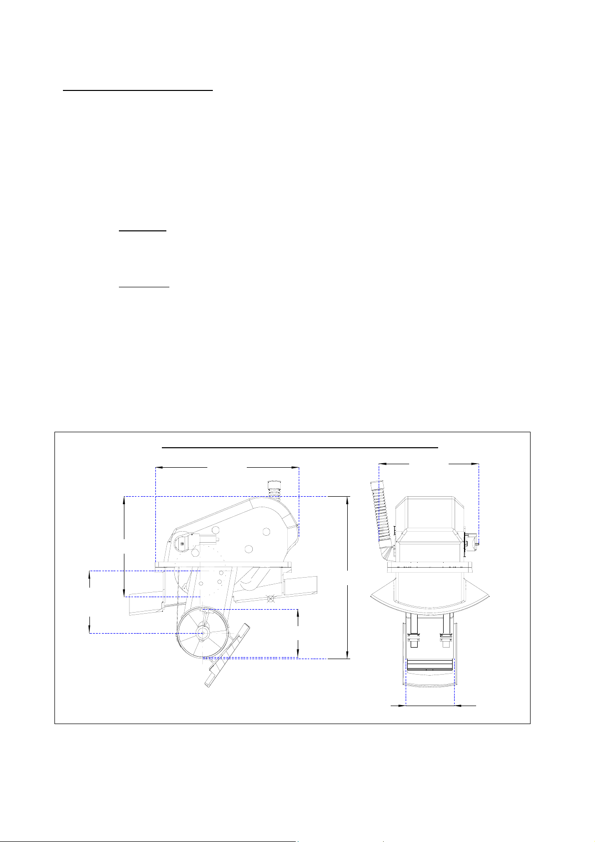
Compact Retract 12/24V Principal Dimensions
555mm
387mm
625mm
241mm
( Stroke )
185mm
Total Unit Weight: 40 kg
When fixing the mounting base, do not forget to take into account the overall dimensions of the
Compact Retract
385mm
185mm
4
English Manual: Compact Retract 12/24V, Version 2 14/04/2005
tolerances
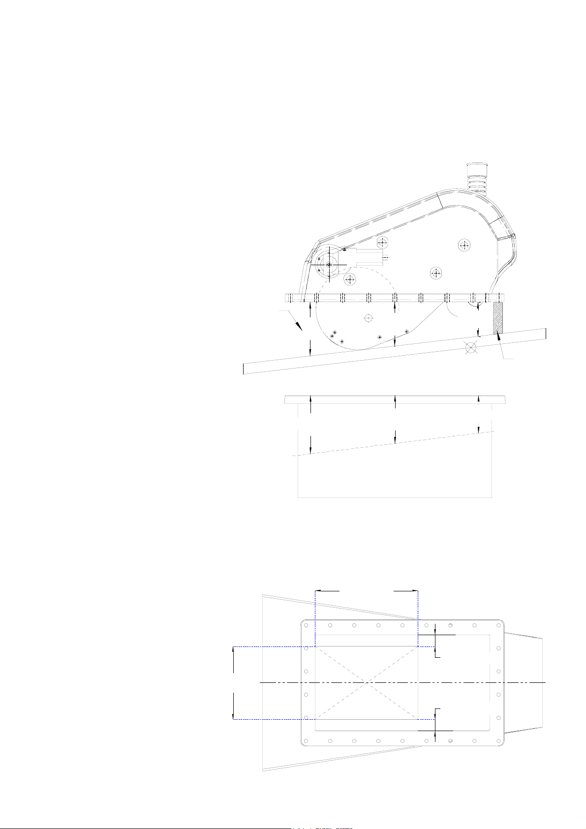
3.2 DETERMINING & MARKING UP POSITION
a) Remove the counter-mould on the inside of the hull ,in area where thruster will be installed,
allowing at least 15 cm on the outside of mounting base position for stratifying the mounting
base to the hull.
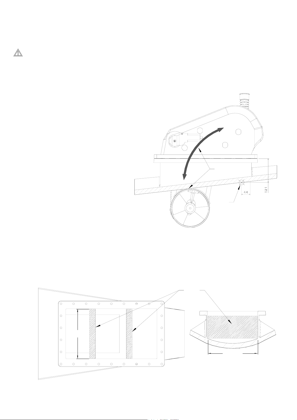
b) Position the thruster inside
the hull. Cut a piece of
wood( length = 121mm –
hull thickness) to use as a
spacer. Place this spacer
between the thruster’s
flange and hull. This will
give the installation height
and position of the unit.
c) When satisfied with the
initial position of the unit,
take measurements at
various points between the
flange and the bottom of
the hull. Mark these
measurements onto the
mounting base to determine
the initial shape to which
the base should be cut. To
allow sufficient tolerance,
add 5 mm to all the above
measurements to allow for
.
( c )
x
l
l
u
H
x + 5mm
Thruster Unit
y + 5mm
Mounting Base
y
z
z + 5mm
BOWSTERN
u
H
( b )
l
l
d) Mark-up the thrusters initial position on the inside of the hull before removing unit.
e) The thruster unit can now be removed and once the mounting base has been cut, using the
above measurements, the base can be temporarily fixed in place in its marked position.
f) Place the thruster unit in the temporarily fixed mounting base to verify dimensions.
g) Once satisfied
clearly mark the
final position of the
inside of the
mounting base and
remove base.
h) Measure and mark
the hull opening
using the
dimensions noted
on the diagram
opposite. Also see
“Build Drawing”.
195mm
STERN
267mm
29.5mm
Final Hull
Opening
29.5mm
Mounting Base
BOW
Hull
Inside
5
English Manual: Compact Retract 12/24V, Version 2 14/04/2005
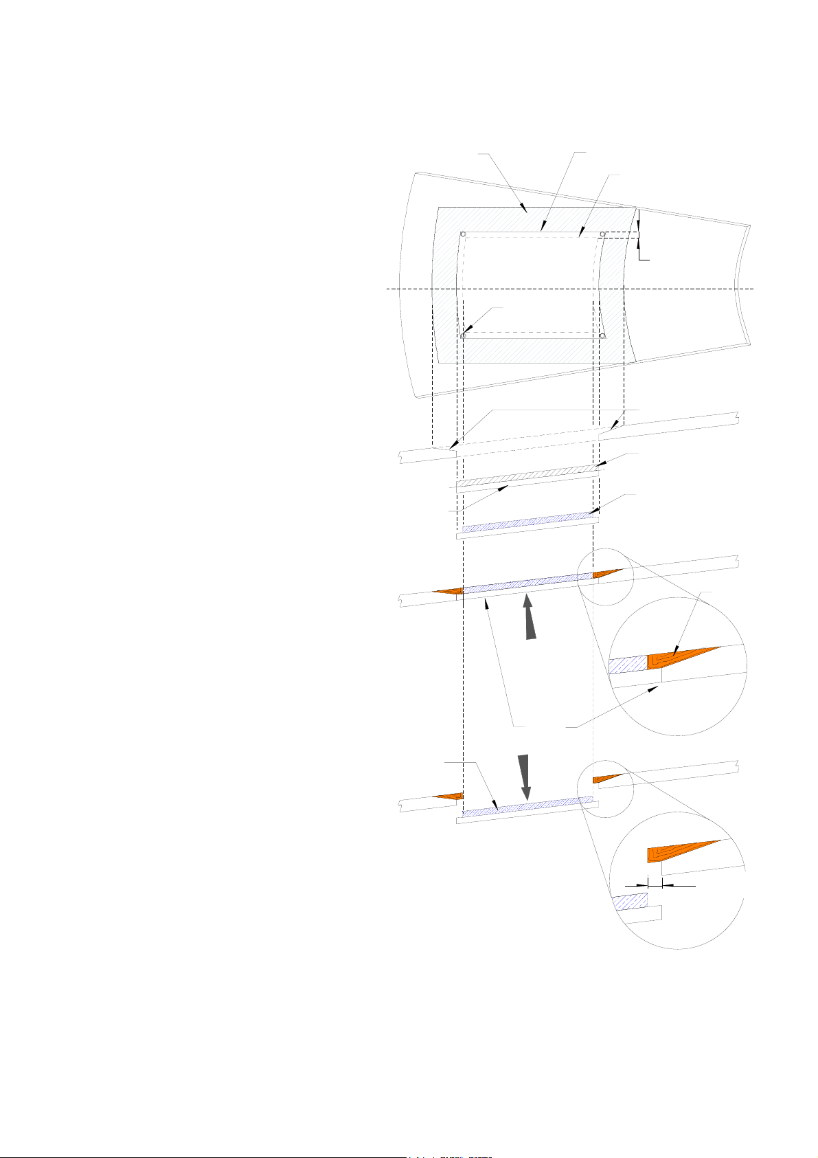
3.3 CONSTRUCTION OF THE HULL OPENING AND CLOSING PLATE
a) Measure & mark the hull opening
as mentioned before.
( c )
( b )
( a )
b) Trace a parallel line, 10 – 15 mm
away from marked-up hull
opening, to allow for position of
rebate.
c) Trace a parallel line, 100 – 150
mm away from marked-up
( d )
10 - 15mm
Hull
Inside
position of rebate, to allow for
area to be shaved down to allow
for the construction of the
rebate.
( e )
d) Drill holes in the corners of lines
marking the rebate position and
( f )
cut out this piece of the hull.
e) Shave down the marked up area
Hull-cut out
( g )
for construction of rebate ( see
“c” above ). Make sure when
grading the hull not to exceed ½
the hull thickness.
f) Shave down hull-cut out to half
its original thickness.
g) Use piece of wood (195 x 267
mm) to make male mould for
rebate construction. Position &
( h )
temporarily fix this on shaved
down hull cut-out, allowing 10 –
( j )
15 mm all-round. Make sure all
lines are smooth and liberally wax
this mould.
h) Position & secure this in hull
opening, making sure outside hull
lines are smooth.
i) Build the rebate, using matt &
roving on the inside of the hull.
Do not exceed the original
thickness and shape of the hull.
j) Once rebate is set, remove the male plug. Now remove temporarily fixed piece of wood from
shaved down hull cut-out and keep the hull cut-out to use as closing plate.
l
l
u
H
l
l
u
H
( i )
l
l
u
H
Rebate
10 - 15 mm
6
English Manual: Compact Retract 12/24V, Version 2 14/04/2005
3.4 FINAL FITTING OF THE MOUNTING BASE TO HULL
WARNING : Please keep in mind that thruster unit will automatically retract after 10 minutes,
when in “Normal Operation Mode”. Thus before doing any work on the turbine, please ensure
that thruster is in “Manual Mode”. When in doubt remove fuse in supply of the electronic
control box.
a) Once the hull opening has
been cut and rebate
constructed, you need to
temporarily fix the mounting
STERN
BOW
base in its marked position.
Install the thruster in
position, fixing it with four
bolts at the corners, raise
and lower the unit, making
sure that the unit is not
being obstructed by
anything and that the
( a )
turbine completely clears the
hull when fully down;
b) IMPORTANT verify that the
( b )
construction point, as
shown on “Build Drawing”
has been respected.
c) Once completely satisfied with the position and height of the mounting base, the base can be
permanently stratified and fixed into the hull while respecting the inside dimensions of the
mounting base. In order to ensure that the mounting base keeps its initial form during the
stratification process, one can use some wooden spacers ( length = 249 mm) on the inside of
the mounting base.
( c )
STERN
BOW
249mm
Mounting Base
Hull
Inside
Mounting Base
249mm
7
 Loading...