

MaxPac X7DAL-E, Single-Screen 8230, Dual-Screen 8230, Triple-Screen 8230 Reference Manual

MaxPac Single/Dual/Triple
Screen 8230 XRA1/2/3 Rev-A
Training and Maintenance Guide
Maintaining and Repairing Your MaxPac
Single/Dual/Triple-Screen 8230 XRA1/2/3 Rev-A
High-Performance Transportable Workstation
MaxVision Corporation
495 Production Avenue
Madison, AL 35758, USA
Part Number: 209-0054-0

ii MaxPac Single/Dual/Triple-Screen 8230 Training and Maintenance Guide
Warranties and Liabilities
MaxVision Corporation warrants that the Product, in the course of its normal use, will conform to MaxVision's
specifications and be free from defects in material and workmanship for a period of twelve (12) months from the date of
the original sale. Such warranty commences on the purchase date appearing on the invoice. The original end user is
entitled to customer support through telecommunication during normal MaxVision business hours and email support to be
responded to as support staff are available. Such support shall be limited to hardware operations and the software
required operating such hardware. Upon written request and subject to the availability of MaxVision personnel, additional
support may be provided by MaxVision in its sole discretion on a time and materials basis.
Limited Warranty for Software. MaxVision warrants to the original end user only that the Software as delivered at the
time of purchase will perform in MaxVision hardware, and that the original diskettes or compact disks are free from
defects in material and workmanship under normal use, for a period of thirty (30) days from the date of original sale,
provided the Software is used with a MaxVision unit. MaxVision makes no warranty that the Software will work in
combination with any hardware or software products provided by third parties, that the operation of the Software will be
uninterrupted or error-free, or that all defects in the Software will be corrected. This limited warranty is void if failure of the
Software has resulted from accident, abuse, or misapplication. MaxVision's entire liability, and your sole and exclusive
remedy shall be, at MaxVision's option, either to (a) correct or help you work around or avoid a reproducible Error or (b)
replace defective diskettes or compact disks. Any replacement Software will be warranted for the remainder of the original
Limited Software Warranty Period.
Limited Warranty for the Product. MaxVision warrants to the original end user only that all Products sold by MaxVision
will be free from defects in material and workmanship and conform substantially to the applicable standards set forth in
the Documentation, under normal use, for a period of 365 days from the date of original sale. This limited warranty is void
if failure of the Product has resulted from accident, abuse, or misapplication. If MaxVision confirms a Product is defective
after you have obtained a Return Materials Allowance Number for such Product and, at your expense, have returned the
Product to MaxVision for inspection, MaxVision will, at its election, repair or replace such Product at no charge to you.
Replacement Product may be either new or remanufactured. In the event that the Product returned is not defective, you
will be responsible for freight costs for return shipment to you. The foregoing warranty shall not apply to Product that has
been (a) damaged by accident, Acts of God, shipment, improper installation, abnormal physical or electrical stress,
misuse or misapplication, as determined by MaxVision in its sole reasonable discretion, or (b) modified without
MaxVision's express written acceptance of such modification for warranty purposes. MaxVision reserves the right to
charge additional fees for repairs or replacements performed outside the Warranty Period. Any replaced or repaired
components, subassemblies or units as well as spare parts are warranted for thirty (30) days or the remainder of the
original warranty period, whichever is longer. MaxVision shall not be responsible for any software, firmware, information or
memory data of yours contained in, stored on, or integrated with any Products returned to MaxVision pursuant to any
warranty under this Agreement.
Disclaimer of Warranties. EXCEPT AS SPECIFICALLY PROVIDED ABOVE, NEITHER MAXVISION NOR ITS
LICENSORS OR SUPPLIERS PROVIDES ANY WARRANTY OF ANY KIND FOR THE SOFTWARE OR THE
PRODUCT, WHETHER EXPRESS, IMPLIED, STATUTORY OR OTHERWISE, INCLUDING BUT NOT LIMITED TO
WARRANTIES OF MERCHANTABILITY, FITNESS FOR A PARTICULAR PURPOSE, AND NON-INFRINGEMENT OF
THIRD PARTY RIGHTS. EXCEPT AS SET FORTH IN THIS AGREEMENT, THE ENTIRE RISK AS TO THE QUALITY
AND PERFORMANCE OF THE SOFTWARE AND THE PRODUCT IS WITH YOU. If a disclaimer of implied warranties is
not permitted by law, the duration of any such implied warranty is limited to ninety (90) days from the date of purchase by
the original end user. Some jurisdictions do not allow the exclusion of implied warranties or limitations on how long an
implied warranty may last, so such limitations or exclusions may not apply to you. This limited warranty gives you specific
legal rights, and you may also have other rights which vary from jurisdiction to jurisdiction.
Liability Exclusions and Limitations. IN NO EVENT SHALL MAXVISION OR ITS LICENSORS OR SUPPLIERS BE
LIABLE FOR ANY INDIRECT, SPECIAL, INCIDENTAL, EXEMPLARY OR CONSEQUENTIAL DAMAGES OF ANY KIND
(INCLUDING LOST PROFITS, LOSS OF USE OR INTERRUPTION OF BUSINESS), OR FOR LEGAL FEES, ARISING
OUT OF THE USE OF THE SOFTWARE OR THE PRODUCT, REGARDLESS OF THE FORM OF ACTION, WHETHER
IN CONTRACT, TORT (INCLUDING NEGLIGENCE), STRICT PRODUCT LIABILITY OR OTHERWISE, EVEN IF
MAXVISION OR ITS LICENSORS OR SUPPLIERS HAVE BEEN ADVISED OF THE POSSIBILITY OF SUCH
DAMAGES. IN NO EVENT WILL COMPANY'S AGGREGATE LIABILITY HEREUNDER EXCEED THE PURCHASE
PRICE PAID BY YOU. This limitation shall apply notwithstanding any failure or inability to provide the limited remedies set
forth above. Some jurisdictions do not allow the exclusion or limitation of incidental or consequential damages, so the
above limitation(s) or exclusion(s) may not apply to you.

MaxPac Single/Dual/Triple-Screen 8230 Training and Maintenance Guide iii
Proprietary Rights-Contracts with Certain U.S. Government Agencies. If the Software is acquired under the terms of
a Department of Defense or civilian agency contract, the Software is "commercial item" as that term is defined at 48
C.F.R. 2.101 (Oct. 1995), consisting of "commercial computer software" and "commercial computer software
documentation" as such terms are used in 48 C.F.R. 12.212 of the Federal Acquisition Regulations and its successors
and 48 C.F.R. 227.7202-1 through 227.7202-4 (June 1995) of the DoD FAR Supplement and its successors. All U.S.
Government end users acquire the Software with only those rights set forth in this Agreement.
Export Restrictions. You acknowledge that the laws and regulations of the United States restrict the export and re-export
of certain commodities and technical data of United States origin, including the Product and the Software, in any medium.
You agree that you will not knowingly, without prior authorization if required, export or re-export the Software or the
Product in any medium without the appropriate United States and foreign government licenses.
Severability. You acknowledge and agree that each provision of this Agreement that provides for a disclaimer of
warranties or an exclusion or limitation of damages represents an express allocation of risk, and is part of the
consideration of this Agreement. Invalidity of any provision of this Agreement shall not affect the validity of the remaining
provisions of this Agreement.
General. This Agreement is the entire agreement between you and MaxVision relative to the Product and the Software,
and supersedes all prior written statements, proposals or agreements relative to its subject matter. It may be modified only
by a writing executed by an authorized representative of MaxVision. No MaxVision reseller or sales representative is
authorized to make any modifications, extensions or additions to this Agreement. This Agreement is governed by the laws
of the State of Alabama without application of the principles of conflicts or choice of laws. The application of the United
Nations Convention on Contracts for the International Sale of Goods to this Agreement is expressly excluded.
Copyright
The materials in this document are the copyrighted works of MaxVision Corporation, copyright © 2005-2006. All rights
reserved. Email sales@maxvision.com for permission to duplicate and otherwise re-use.
Trademarks
MaxVision, and MaxPac are registered trademarks, and MaxPro and TeraPac are trademarks, of MaxVision Corporation.
Microsoft and Windows are registered trademarks of Microsoft Corporation. Intel and Pentium are registered trademarks
and Xeon is a registered trademark of Intel Corporation. Other trademarks and registered trademarks are the property of
their respective owners.
Regulatory Approvals
EN60950, EN55024, EN55022, FCC, Part 15, EN61000-3-2 & EN61000-3-3.
Warnings
Changes or modifications to this device that are not approved by the party responsible for compliance could void the
user’s authority to operate the equipment.
Each type of MaxPac system should be re-shipped only in the Pelican case and/or other packaging materials in
which the system was first delivered to the customer. Damage caused by shipping systems using unapproved
Pelican cases and/or other packaging materials is NOT covered by MaxVision's warranty.
To reduce the risk of electrical shock, do not attempt to open the device unless instructed to do so. Do not use any tool for
purposes other than instructed.
A Lithium Ion battery is included with the system motherboard. This battery is used for the Real Time Clock (RTC) circuit.
The expected lifetime of the battery is approximately 5 years. There is a danger of explosion if this battery is incorrectly
replaced. Replace only with the same or equivalent type recommended by the motherboard manufacturer. Dispose of
used batteries according to the manufacturer’s instructions.

iv MaxPac Single/Dual/Triple-Screen 8230 Training and Maintenance Guide
Contents
Legal and Related Information
Warranties and Liabilities..................................................................................................................................... ii
Copyright............................................................................................................................................................. iii
Trademarks ......................................................................................................................................................... iii
Regulatory Approvals.......................................................................................................................................... iii
Warnings ............................................................................................................................................................. iii
Chapter 1: Troubleshooting Tips for 8230 XRA1/2/3 Systems ........................................................................... 1
Chapter 2: Motherboard Diagrams ........................................................................................................................ 3
Chapter 3: Setting-Up the Software/Devices/Network/RAID Array..................................................................... 5
Setting-Up the Network ....................................................................................................................................... 5
Setting-Up the Graphics...................................................................................................................................... 5
Adjusting the Screens ......................................................................................................................................... 6
Setting Up Video Input for Picture-in-Picture (Dual- and Triple-Screen Configurations Only) ........................... 6
Configuring the RAID Array (with Separate System Drive) ................................................................................ 8
Configuring the RAID Array (with Hot Spare and System Partition on RAID Array)......................................... 22
Chapter 4: Module Replacement and Upgrade Procedures for Single-Screen Systems............................... 33
Introduction ....................................................................................................................................................... 33
Required Tools and Techniques ....................................................................................................................... 33
Names and Types of Screws ............................................................................................................................ 33
Flat Panel Display Module ................................................................................................................................ 34
Opening the Display Assembly into its Service Position................................................................................... 40
Memory ............................................................................................................................................................. 43
PCI Cards (General) ......................................................................................................................................... 44
PCI Express Card (Primary).............................................................................................................................. 45
Power Distribution Assembly ............................................................................................................................ 47
Hard Drive Magazine (also Individual Hard Drives).......................................................................................... 50
Optical Drive (CD/DVD) .................................................................................................................................... 51
Optical Drive (CD/DVD) Backplane .................................................................................................................. 51
External Cooling Fan Assembly........................................................................................................................ 53
CPU Cooling Fans ............................................................................................................................................ 54
Main Power Supply Unit (PSU)......................................................................................................................... 55
Motherboard...................................................................................................................................................... 57
Chapter 5: Module Replacement and Upgrade Procedures for Dual/Triple-Screen Systems....................... 65
Introduction ....................................................................................................................................................... 65
Required Tools and Techniques ....................................................................................................................... 65
Names and Types of Screws ............................................................................................................................ 65
Flat Panel Display Module (Left-Hand Screen)................................................................................................. 66
Flat Panel Display Module (Right-Hand Screen) .............................................................................................. 67
Flat Panel Display Module (Center Screen)...................................................................................................... 68
Opening the Display Assembly into its Service Position................................................................................... 72
Memory ............................................................................................................................................................. 74
PCI Cards (General) ......................................................................................................................................... 75
PCI Express Card (Secondary card for third screen and Projector Port) ........................................................ 76
PCI Express Card (Primary).............................................................................................................................. 77
Power Distribution Assembly ............................................................................................................................ 79
Hard Drive Magazine (also Individual Hard Drives).......................................................................................... 82
Optical Drive (CD/DVD) .................................................................................................................................... 83
Optical Drive (CD/DVD) Backplane .................................................................................................................. 84

MaxPac Single/Dual/Triple-Screen 8230 Training and Maintenance Guide v
External Cooling Fan Assembly........................................................................................................................ 85
CPU Cooling Fans ............................................................................................................................................ 86
Main Power Supply Unit (PSU)......................................................................................................................... 87
Motherboard...................................................................................................................................................... 89
Chapter 6: Installation of the optional UPS Power Management System........................................................ 98
Installing the UPS Hardware............................................................................................................................. 98
Installing the UPS Software ............................................................................................................................ 102
Using the UPS Software ................................................................................................................................. 104
Chapter 7: Optional TeraPac 3 Connection to the MaxPac8230..................................................................... 107
Using the TeraPac 3 with a MaxPac 8230...................................................................................................... 107
Appendix A: Creating and Using Backup Images (Including Restoring Your OS)....................................... 109
Introduction ..................................................................................................................................................... 109
Appendix B: Regular System Maintenance ...................................................................................................... 118
Cleaning Interior Dust ..................................................................................................................................... 118
Replacing the Lithium Battery ......................................................................................................................... 118
Maintaining (Cleaning) the "Baghdad Filters" ................................................................................................. 118
Resetting the Motherboard BIOS.................................................................................................................... 121
Appendix C: Screws and Required Tools ......................................................................................................... 123
Screws............................................................................................................................................................. 123
Required Tools................................................................................................................................................ 124
Appendix D: Contacting MaxVision Support (RMA and Serial Numbers) ..................................................... 125
Repairing/Replacing Products/Accessories .................................................................................................... 125
Contacting Technical Support and RMA Numbers ......................................................................................... 125


MaxPac Single/Dual/Triple-Screen 8230 Training and Maintenance Guide 1
Chapter 1: Troubleshooting Tips for
8230 XRA1/2/3 Systems
1) The MaxPac8230 has both a hard power switch (at power supply itself ---O; --- for ON) and a soft power
momentary switch (on center monitor behind the display controls). If the optional UPS Power
Management System is installed and the 8230 is ON then removing the AC chord or switching the hard
power to O will not shut down the system. Instead the UPS system will beep and provide power through
the batteries. The system must be shut down via Windows or the soft power switch for a complete
shutdown to occur. Failing to do this step when packing up your system will drain your batteries.
2) When AC power is applied to the 8230 the motherboard goes into standby power mode. Some of the
motherboard circuitry is powered waiting on the soft power or other low level command. When the
motherboard first goes into standby (AC power applied with hard power switch ON) the 3 keyboard led’s
will flash green and then turn back off.
3) When the 8230 is powered on via soft power all of the display power LEDs should turn on with an orange
color. During initial startup the primary display will not light-up until a good portion of the POST (Power On
Self Test) sequence is complete. This time delay depends on the amount of memory present but for most
systems is about 10 seconds. Then all 3 of the keyboard LED’s should flash green. Usually the left
keyboard LED will remain lit. If you need to get into the motherboard BIOS depress the Delete key a few
times now. The BIOS will not be entered until initialization is complete including scanning of drives
attached to the RAID controller.
4) At this stage if any of the display LEDs are RED (instead of Orange or Green) then the display is off.
Depress the display power button (next to the display LED) to power up the display. It’s LED will change
from Red to Orange to Green and back to Orange if the display is not receiving a signal. The LED should
stay green if receiving video signals. Also note that each display must have its input set to DVI and NOT
RGB. To change the input source use the Input button on the display. The RGB input can be used if one
of the display’s PIP VGA inputs is connected from an external source (discussed later) and you wish to
display it’s data rather than the 8230 video data. Initial BIOS initialization data only will appear on the
Primary PCI Express graphics board’s displays. This is normally the Center and Right screens. The Left
screen (if present) will show “No signal DVI” until it has been enabled in Windows. Note that the power
state, input mode, etc of each display is saved for subsequent power-up cycles.
5) At this point depressing the Num Lock key (upper left of the numeric keypad) repeatedly will toggle the
left keyboard LED from green to off. This indicates that the CPU and motherboard is responding to
commands even if you see nothing on the displays. If nothing appears on the display(s) in order to further
debug the problem the 8230 must be put into its service position as documented in chapter 4 (8230XRA1)
or chapter 5 (8230XRA2/3).
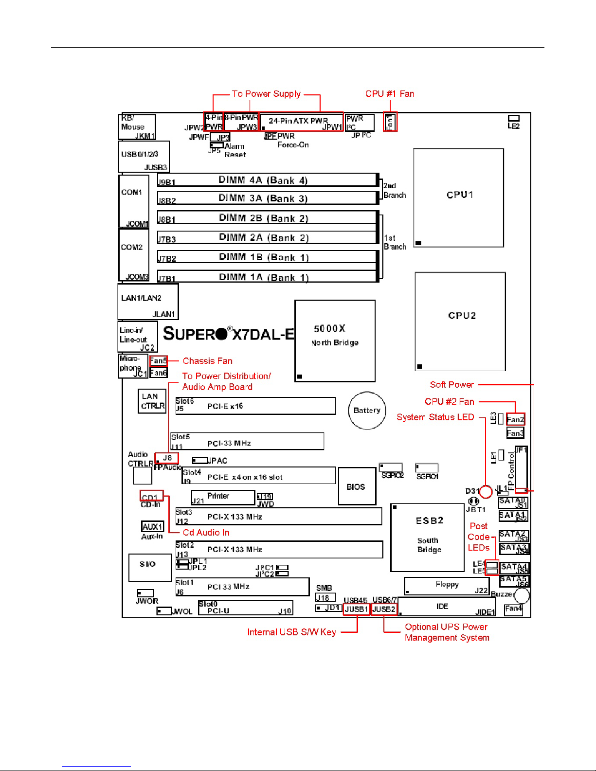
6) With the 8230 in its service position refer to Figure 2-2 and find the System Status LED and Post Code
LEDs. Check for proper seating of the PCI Express graphics boards (the 8230XRA3 requires a 2
graphics board for the left screen). Make sure the Poron is attached to the inside of the inner-chassis lid
as shown in Fig 5-33. Assuming the PCI-E boards are seated observe the LEDs in Figure 2-2. With the
motherboard in standby (after proper shutdown with AC applied) the System Status LED should be
yellow. Also both the yellow and green POST Code LEDs should be on.
7) Now depress the soft power button to turn on your 8230. The System Status LED should turn green. The
POST LEDs should sequence as follows: Yellow ON Green OFF during memory checks; Yellow OFF
Green ON during system shadowing checks; Yellow ON Green ON during final CPU checks; then Both
OFF just prior to the keyboard LED’s flashing.
nd
PCI-E

2 MaxPac Single/Dual/Triple-Screen 8230 Training and Maintenance Guide
8) If after system startup the POST LED stick at the Yellow ON Green OFF state then the FBDIMM memory
is not being seen. Refer to the Memory Section of chapter 4 or 5. Note that memory must be installed in
pairs starting with DIMM 1A/1B (Fig 2-2). This means that a bad (or poorly seated) FBDIMM in slot 1A or
1B could cause NONE of the memory to be seen (even in slots 2A and beyond). Note that slots 3A and
4A do not require population in pairs (but must be in order). Memory failures are sometimes just seating
problems so reseating is worth trying. If memory is still failing and you have 4 FBDIMM then try each set
in just slots 1A and 1B (1A/1B bank must be populated in all cases).
9) If you are still not getting video and both POST LEDs are off you could have several video related
problems. Unfortunately the motherboard will allow a boot all the way into Windows with the PCI-E
graphics not present or bad. Assuming neither the middle nor right displays are not getting valid video the
fault is probably with the primary PCI-E graphics card. For 8230XRA3 systems (assuming you do not
have a spare PCI-E board) you could temporarily remove the primary PCI-E graphics board. Now the
secondary PCI-E board (for the left display) should become the primary display for the BIOS and
Windows.
10) Assuming you now have video displaying on your middle and right screen you should see the 3ware
BIOS scan for the RAID array and then boot into Windows. If you are sure a valid image exists on the
RAID array (or individual system disk connected to the motherboard) and you still see “Operating System
not found” a Boot order problem likely exists.
11) Reboot your system and use the delete key to enter the BIOS. Use the arrow keys to go to the Boot
section. Now check your boot order. Make sure that your IDE CD is listed before the 3ware Storage
Controller in the upper part of the screen (listed 1-8). Note that if your system disk is connected directly to
the motherboard it should be listed before the 3ware. If you have connected a USB disk or memory stick
it may be listed ahead of your boot disk. Move it behind your boot disk in this case.
MaxPac Single/Dual/Triple-Screen 8230 Training and Maintenance Guide 3
Chapter 2: Motherboard Diagrams
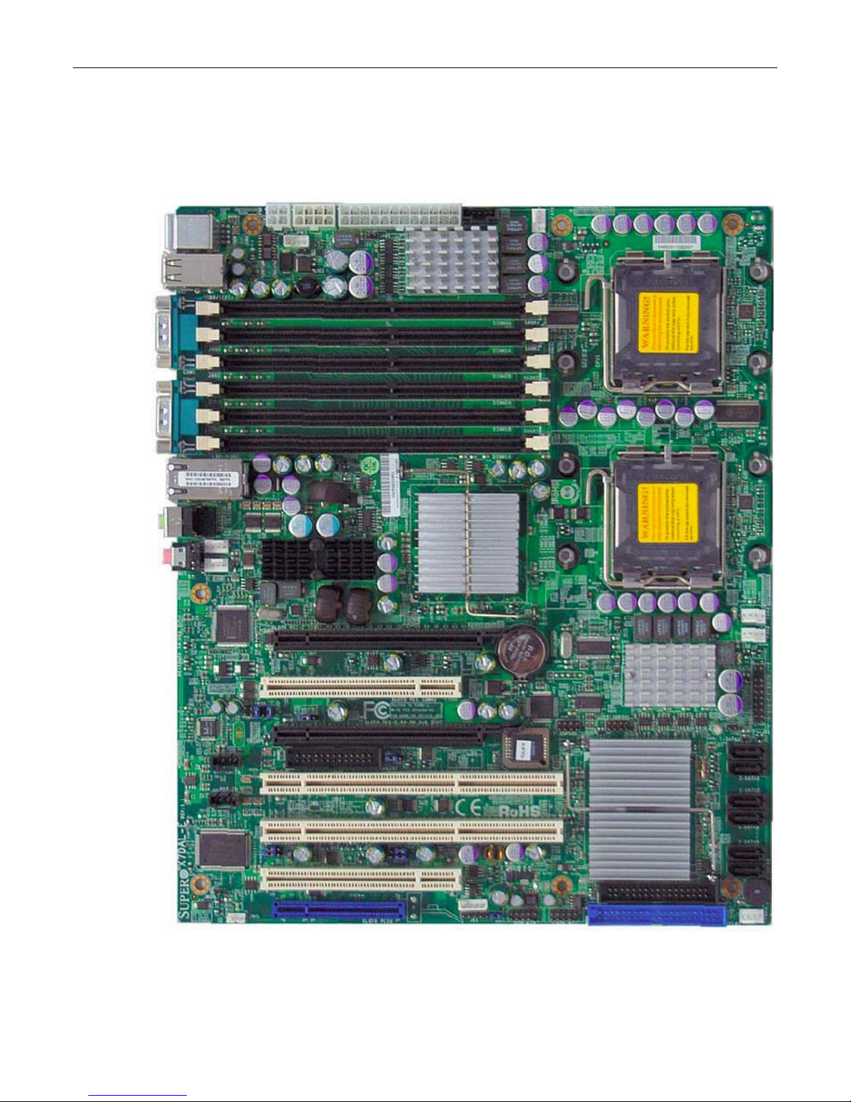
Figure 2-1. Top-down view of the X7DAL-E motherboard.
4 MaxPac Single/Dual/Triple-Screen 8230 Training and Maintenance Guide
Figure 2-2. Cable connections and LEDs on the X7DAL-E motherboard.

MaxPac Single/Dual/Triple-Screen 8230 Training and Maintenance Guide 5
Chapter 3: Setting-Up the
Software/Devices/Network/RAID Array
Setting-Up the Network
In the majority of environments, it is sufficient to use the Windows XP defaults for the network. Simply
connect the network cable (Figure 3-1) and the system should auto-detect the presence of the
network and the data/communications light next to the network cable connector should start to flash.
Figure 3-1. Connecting the network cable
The easiest way to test your network connection is to invoke your web browser and visit a website
such as www.MaxVision.com. In the event of any problems or special requirements, you should first
consult your on-site IT representative (if the problems persist, contact MaxVision support as
discussed in Appendix D).
Setting-Up the Graphics
When you receive your MacPac dual/triple-screen X-Class system, you will find that the graphics
subsystem has been pre-installed with the following (recommended) characteristics:
• Color Quality: Highest (32-bit)
• Resolution: 1, 2, or 3 x 20.1” displays: 1600 x 1200
Irrespective of the configuration, the graphics on your system will have been custom pre-configured to
suite your particular requirements.
MaxPac systems are available with a variety of different graphics cards depending on your unique
application. The standard configuration for a triple-screen system, for example, is to have the center
and right-hand displays controlled by a PCI Express-based NVIDIA Quadro FX4500 graphics card,
while the left-hand display and projector port are controlled by a second PCI Express-based NVIDIA
Quadro FX-series board.
Note: OpenGL™ acceleration is now available all displays controlled by the PCI Express-based
NVIDIA Quadro FX series controllers. This allows the user to run applications requiring OpenGL
acceleration on all displays as long as all are controlled by the same NVIDIA Graphics driver.
6 MaxPac Single/Dual/Triple-Screen 8230 Training and Maintenance Guide
If you do have a special graphics card, you may consult the manual associated with this card (this
manual will be included in your documentation package as discussed in Chapters 1 and 2) or contact
MaxVision support (as discussed in Appendix D) for more information.
Adjusting the Screens
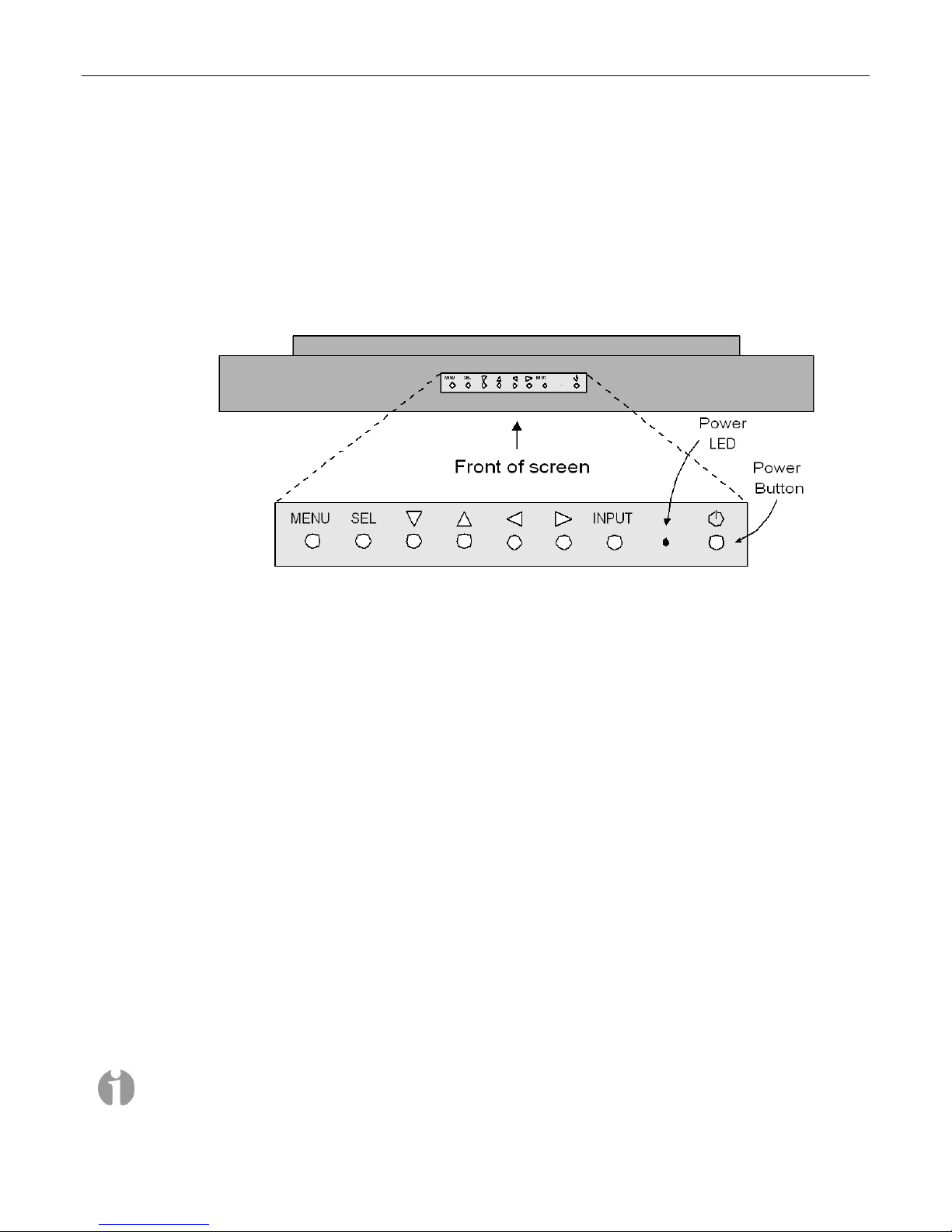
In the case of a dual-display or triple-display configuration, each screen has a set of controls mounted
on the top of the display (Figure 3-2). (In the case of a single-display system, these controls are
located on the left-hand side of the unit next to the CD/DVD optical drive.)
Figure 3-2. Top-down view of screen controls on dual- and triple-display systems
Observe the power button located to the right of the power light-emitting diode (LED). This is an
independent power button for the display/screen.
Pressing the MENU button will bring up a series of items on the screen. Use the up/down buttons to
move between these items; press and release the SEL button to select that item; and use the
right/left buttons to vary the settings.
Some custom configurations allow the display to be driven from multiple sources. In this case,
pressing the INPUT button selects between digital and analog inputs. These custom configurations
will come equipped with a special documentation addendum that details the actions of the INPUT
button; in the case of standard configurations, the source should always be set to “Digital.”
Setting Up Video Input for Picture-in-Picture
(Dual- and Triple-Screen Configurations Only)
In the case of a MaxPac 8230 XRA2 (dual-screen) system, the right-hand monitor supports multiple
inputs: the default DVI-I input from the system and an external VGA input that can be used for
picture-in-picture monitoring purposes. Similarly, in the case of a MaxPac 8230 XRA3 (triple-screen)
system, both the left- and right-hand monitors support this capability.
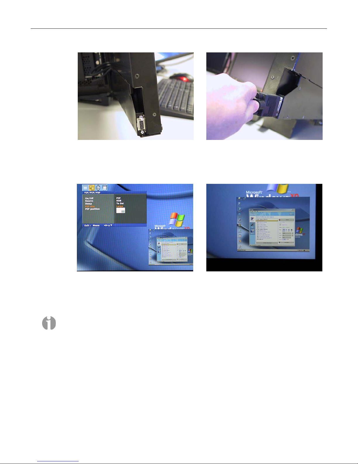
1) Observe the VGA connector associated with the left-hand screen (Figure 3-3). The external video
source would be fed into this connector as shown for the right-hand screen (Figure 3-4).
Note: For the purposes of this example, the video signal being used as input to the right-hand
screen originates from another PC. In reality, this input could come from any VGA video source
with a resolution no higher than 1024 x 768.
MaxPac Single/Dual/Triple-Screen 8230 Training and Maintenance Guide 7
Figure 3-3
Figure 3-4
2) In order to access the external video source, press the Menu button in the controls mounted on
the top of that display (Figure 3-2), and then use the left/right arrow buttons on this control panel
to access the Picture-in-Picture dialog (Figure 3-5)
Figure 3-5
Figure 3-6
3) Use this dialog to turn the Picture-and-Picture window On/Off and to specify characteristics such
as the size and position of the Picture-and-Picture window (located in the lower right-hand corner
of the screen in Figures 3-5 and 3-6.)
Note: The video source and the Picture-in-Picture window must be set to the same resolution,
which must be less-than or equal-to 1024 x 768.
8 MaxPac Single/Dual/Triple-Screen 8230 Training and Maintenance Guide
Configuring the RAID Array (with Separate System Drive)
Note: Your MaxPac8230 may be configured for connection to the optional TeraPac3 8 drive SATA
Expansion. In this case the MaxPac8230 will include a 12 or 16 port SATA RAID 5 controller. This
chapter illustrates and assumes a 4 port SATA RAID 5 controller so the photos may be somewhat
different. Refer to Chapter 7 for a brief section on the MaxPac8230 connection to the TeraPac3 and
to the TeraPac3 User Operation and Maintenance Guide for more details.
Note that these discussions reflect system configurations with a separate system drive as illustrated
in Figures 3-7 and 3-8). Configurations that have the system partition established on the RAID array
itself (leaving a hot-spare drive) are discussed later in this chapter.
When you take possession of your MaxPac 8230 system, the RAID system will already have been
established, initialized, and verified. The instructions in this section are intended to address those rare
situations where you need to replace a degraded/failed drive or you wish to rebuild the RAID system
from the ground up.
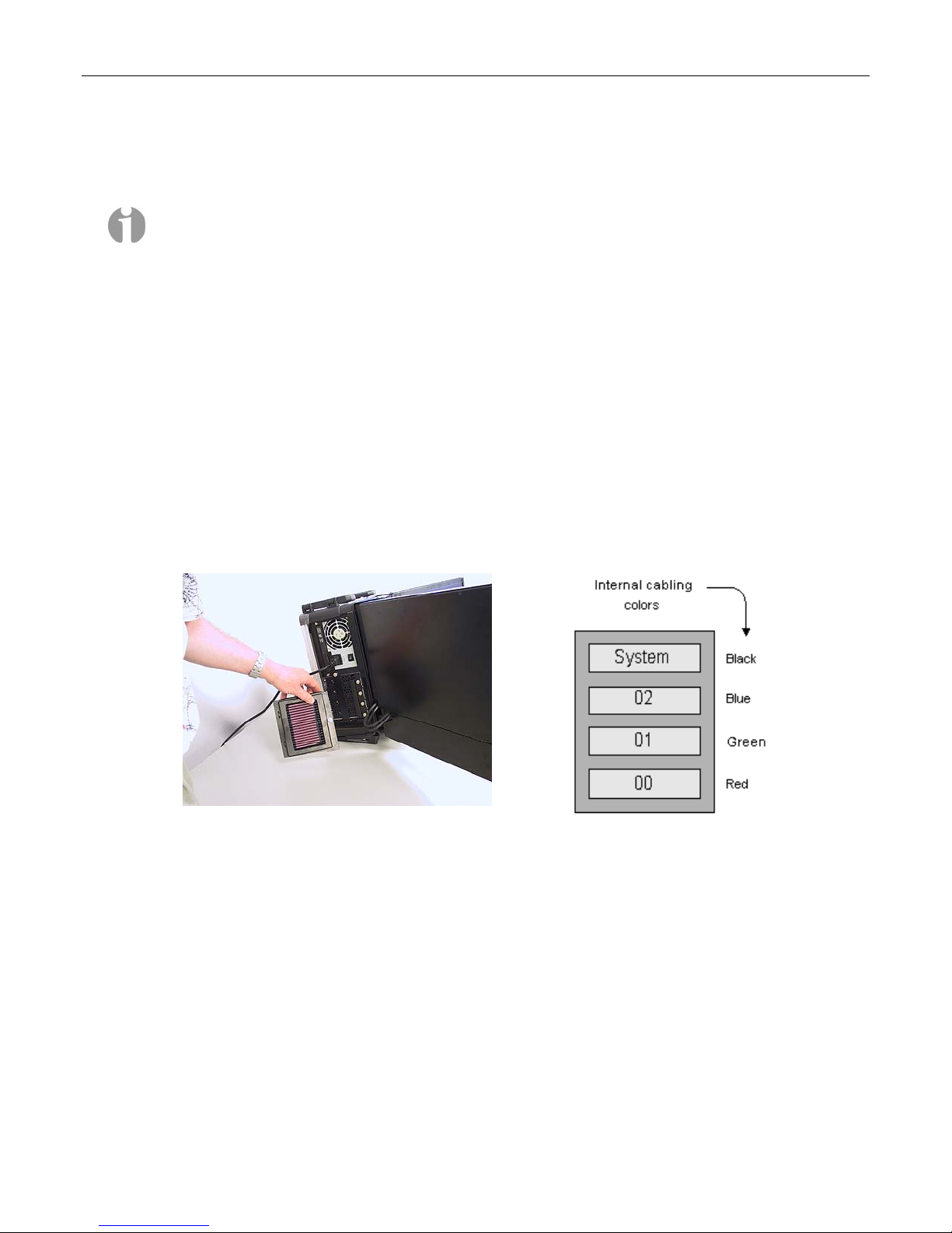
Your MaxPac system can contain up to four SATA hot-swappable hard disk drives presented in a
4-drive disk caddy. This caddy is located on the lower left-hand side of the main chassis under the
"Baghdad Filter" assembly as shown in Figure 3-7 (the numbering of the disks is as shown in
Figure 3-8). In the case of a typical RAID 5 system, the upper disk is the system disk, while the
lower three disks are used to implement the RAID data array.
Figure 3-7 Figure 3-8
Installing the Web-Based 3ware Software
If you reload your operating system, then you will also need to reload the appropriate RAID driver
followed by 3ware's 3DM 2 web-based RAID management application as follows:
1) Power-up the system. The operating system will see the RAID controller as a new device and will
therefore prompt you to load the appropriate driver from the 3ware CD, which is provided with
your system.
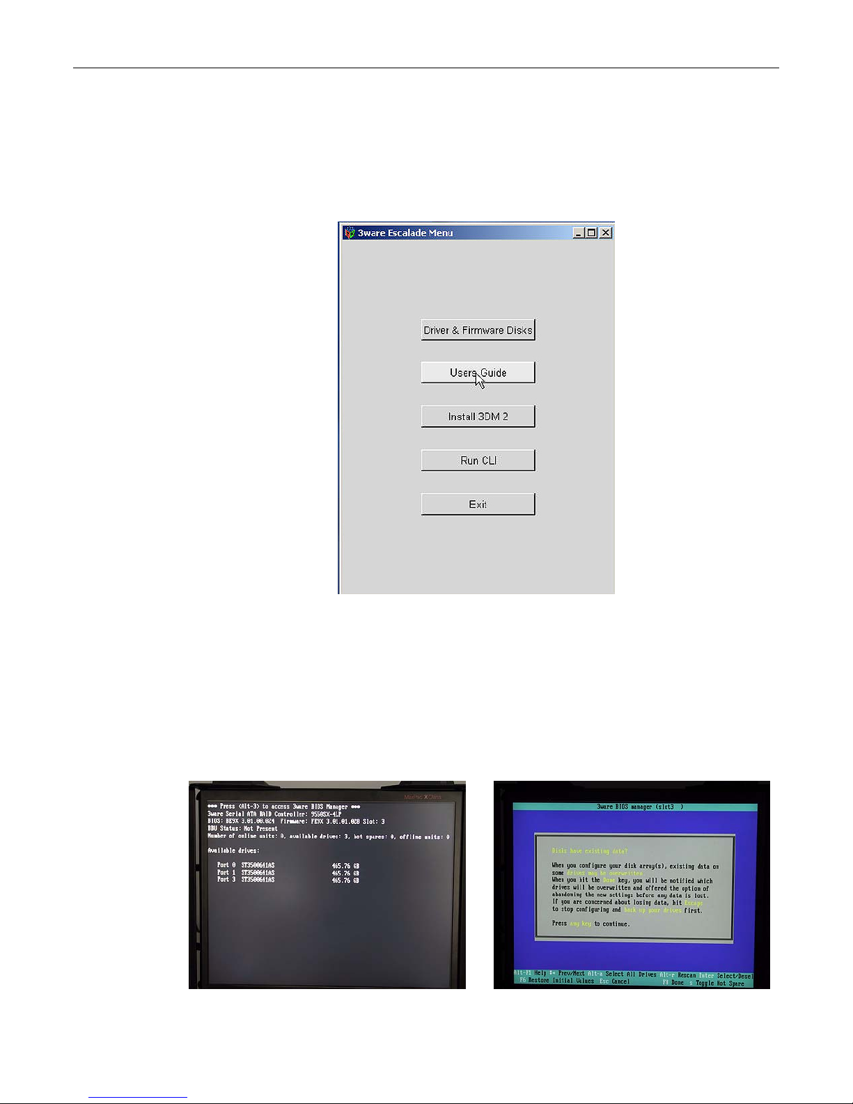
2) Insert the 3ware CD. The auto-play function will bring up the 3ware Escalade Menu as shown in
Figure 3-9. Initially you should ignore this menu; don’t dismiss it, but instead use the operating
system's Device Manager utility to look for the 3ware driver on the CD and install it.
3) Once the 3ware driver has been loaded, return to the 3ware Escalade Menu and click the Install
3DM 2 button.
4) Approve the license agreement in the ensuing pop-up dialog.
MaxPac Single/Dual/Triple-Screen 8230 Training and Maintenance Guide 9
5) Following acceptance of the license agreement, you may be presented with the operating
system's standard Welcome to New Connection Wizard dialog. In this case, use this dialog to
setup your network connection.
6) Following this wizard, 3ware's 3DM 2 software will be installed (when prompted to do so, allow
the installation script to place a 3DM 2 icon on your desktop).
Figure 3-9
Building a New 3ware RAID 5 Array from Scratch
The discussions in this section assume that you have an existing system disk and – for one reason or
another – have installed three new/empty data disks.
1) Start to power-up the system. When you see the BIOS message "<Alt-3> to access 3ware BIOS
Manager" (Figure 2-10) press and hold the <ALT> (alternate) key and – while still holding this key
– press the number "3" key. This will invoke the 3ware BIOS manager; in most cases, you will be
presented with a warning screen as shown in Figure 3-11.
Figure 3-10
Figure 3-11
10 MaxPac Single/Dual/Triple-Screen 8230 Training and Maintenance Guide
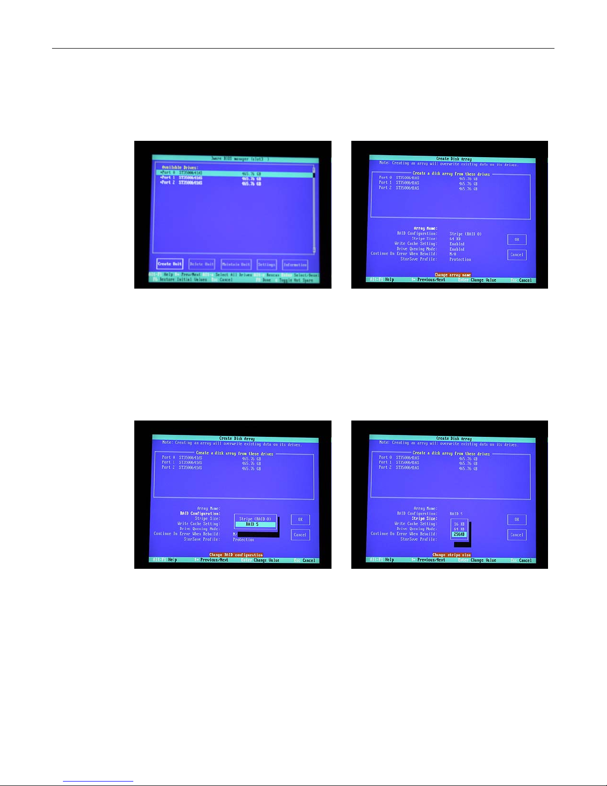
2) Press any key to continue, which will take you fully into the 3ware BIOS Manager. Observe that
the Create Unit option is selected by default. Use <Alt-A> to select all of the drives; asterisk "*"
characters appear to the left of each drive's port number to indicate that the drive has indeed
been selected (Figure 3-12)
Figure 3-12
Figure 3-13
3) Ensure that the Create Unit item is still selected (the white box shown to the bottom left of the
screen in Figure 2-12), and then press the <Enter> key to invoke the Create Disk Array screen
(Figure 3-13).
4) Use the up/down arrow keys to highlight the RAID Configuration item, and then press the
<Enter> key to access an associated pop-up dialog (Figure 3-14).
5) Use the up/down arrow keys to highlight the RAID 5 option, and then press the <Enter> key to
select this option.
Figure 3-14
Figure 3-15
6) Use the up/down arrow keys to highlight the Stripe Size item, and then press the <Enter> key to
access an associated pop-up dialog (Figure 3-15).
7) Use the up/down arrow keys to highlight the 256 KB option, and then press the <Enter> key to
select this option.
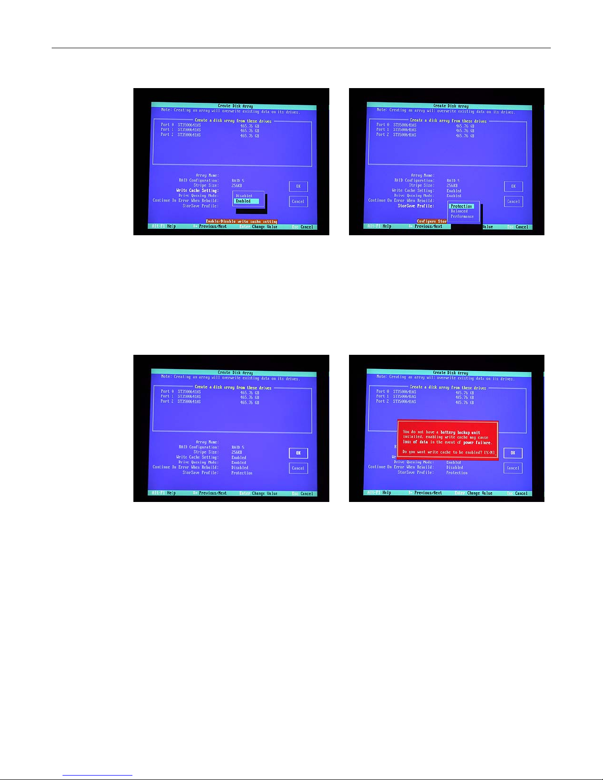
8) Use the up/down arrow keys to highlight the Write Cache Setting item, and then press the
<Enter> key to access an associated pop-up dialog (Figure 3-16).
9) Use the up/down arrow keys to highlight the Enabled option, and then press the <Enter> key to
select this option.
MaxPac Single/Dual/Triple-Screen 8230 Training and Maintenance Guide 11
Figure 3-16
Figure 3-17
10) Use the up/down arrow keys to highlight the StorSave Profile item, and then press the <Enter>
key to access an associated pop-up dialog (Figure 3-17).
11) Use the up/down arrow keys to highlight the Protection option, and then press the <Enter> key
to select this option.
12) Use the up/down/right/left arrow keys to highlight the OK item (Figure 3-18) and then press the
<Enter> key to save your changes.
Figure 3-18
Figure 3-19
13) You will be presented with a warning dialog as shown in Figure 3-19. Press the Y (yes) to allow
the write cache to be enabled (note that this mode significantly improves performance, but it can
result in a loss of data in the event of a power failure, so MaxVision STRONGLY recommends the
use of an uninterruptible power supply (UPS) with your system).
14) At this point, you will be presented with a summary description of the RAID array you have
defined (Figure 3-20).
15) Press the <F8> key to request that your array be established and to exit the 3ware BIOS
setup utility.
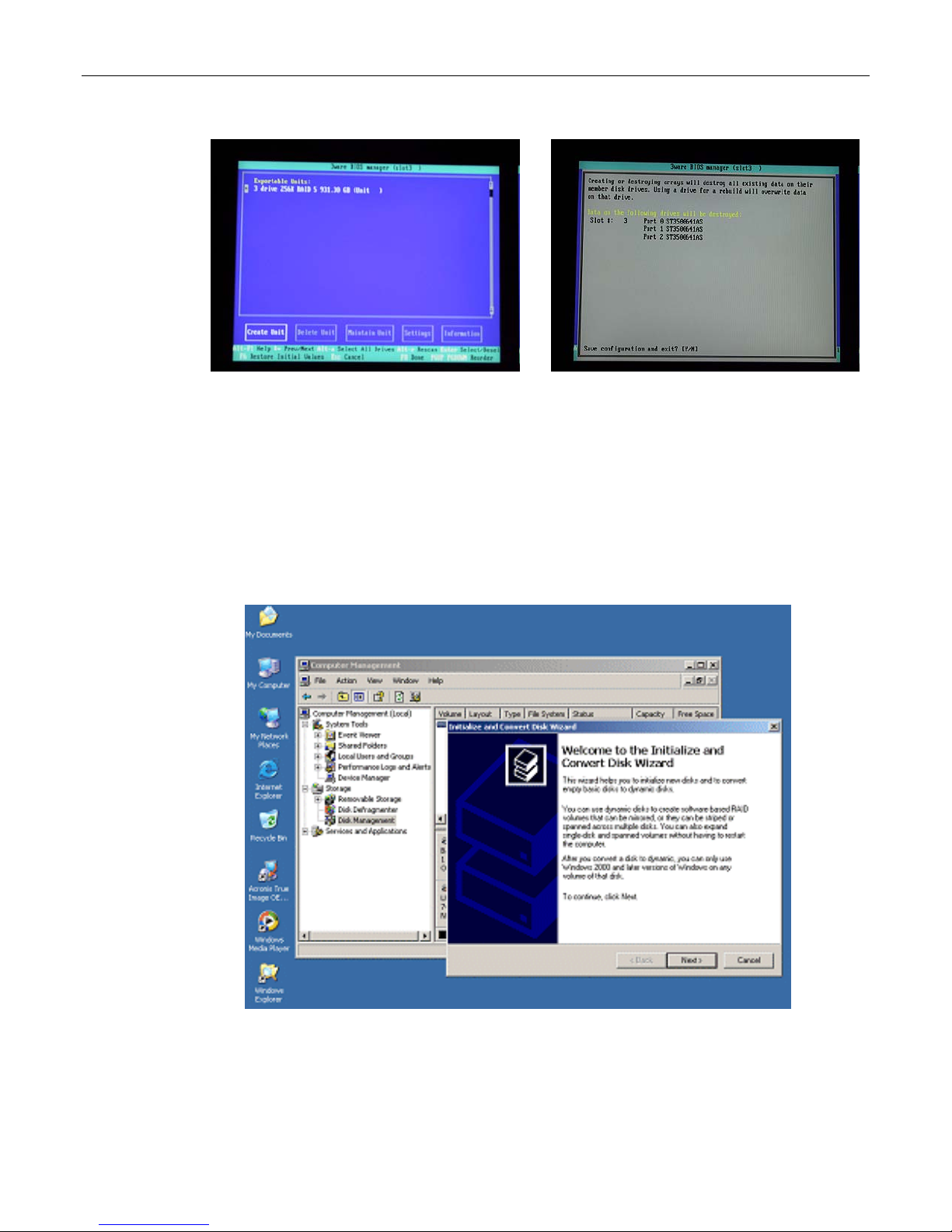
12 MaxPac Single/Dual/Triple-Screen 8230 Training and Maintenance Guide
Figure 3-20
Figure 3-21
16) You will be presented with a warning screen as shown in Figure 3-21. Press the Y (yes) key in
order to establish your array and exit the 3ware BIOS setup utility. The system will automatically
reboot itself in order to make your new RAID array available to the operating system. During the
boot process you will see the BIOS report the existence of your new RAID array.
17) Once the system has booted up into Windows®, right-click on the My Computer icon and then
select the Manage option. In the ensuing Computer Management dialog, click on the Disk
Management item. As you have just created a new RAID array, this will automatically launch the
Initialize and Convert Disk Wizard as shown in Figure 3-22.
18) Click the Next button to be presented with the Select Disk to Initialize screen. Click the Disk 1
item as shown in Figure 3-23.
Figure 3-22. The Initialize and Convert Disk Wizard

MaxPac Single/Dual/Triple-Screen 8230 Training and Maintenance Guide 13
Figure 3-23
Figure 3-24
19) Click the Next button to be presented with the Select Disk to Convert screen. Click the Disk 1
item as shown in Figure 3-24.
20) Click the Next button to be presented with the Completing the Wizard screen as shown in
Figure 3-25, and then click the Finish button to perform the operations and exit the wizard.
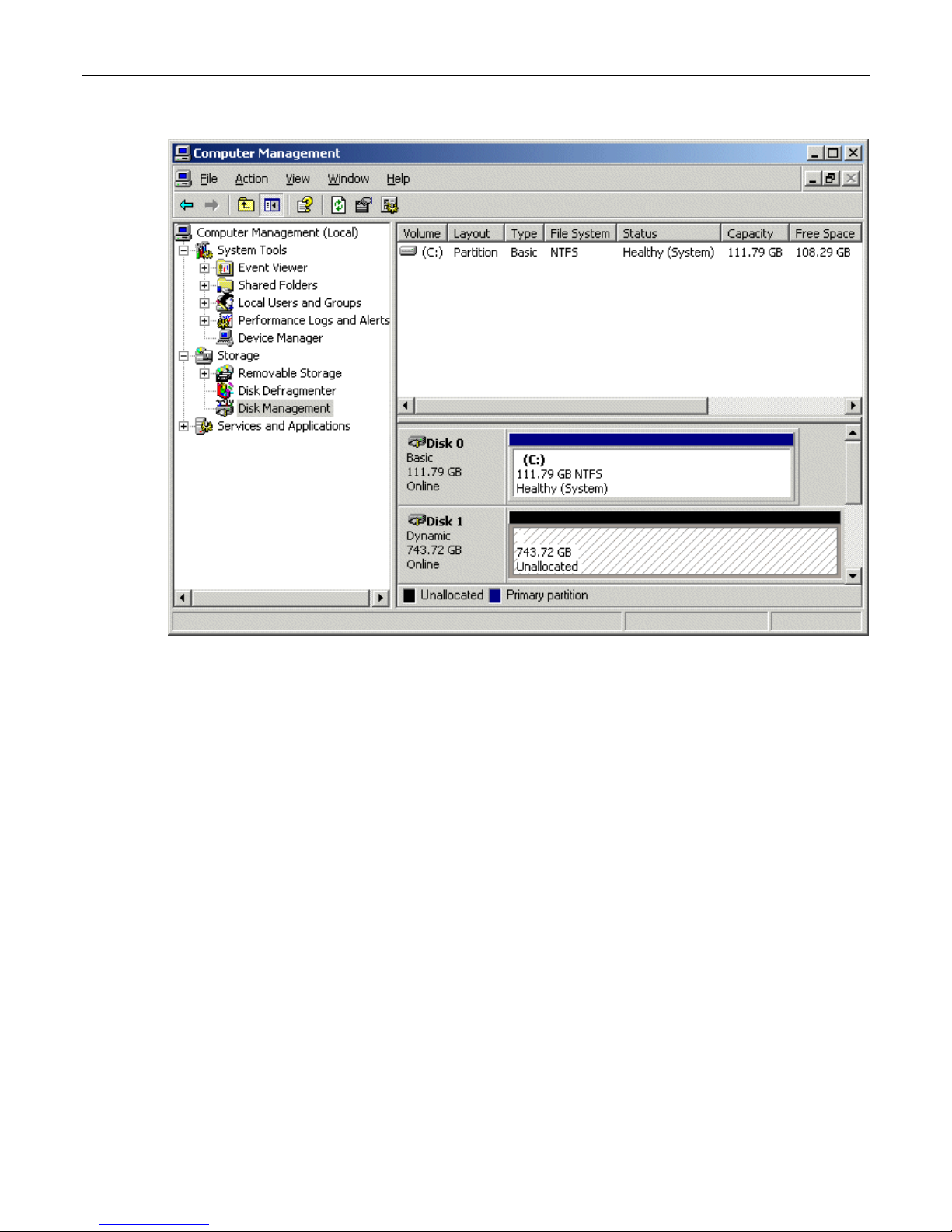
21) Observe that the Disk Management area of the Computer Management dialog now shows Disk 1
as being a Dynamic disk that is – as yet – unallocated as shown in Figure 3-26.
Figure 3-25. The Completing the Wizard dialog
14 MaxPac Single/Dual/Triple-Screen 8230 Training and Maintenance Guide
Figure 3-26. Disk 1 is – as yet - unallocated
Note: In the case of the system used in this example, the system disk was 120 GB in size, while the
three data disks used to form the RAID array were each 400 GB in size.
Observe in Figure 3-26 that Disk 1 is shown as being approximately 800 GB in size, where 800 GB
equates to 2/3 of the 3 x 400 GB capacity of the data disks (the remaining 400 GB is used to provide
the RAID 5 redundancy).
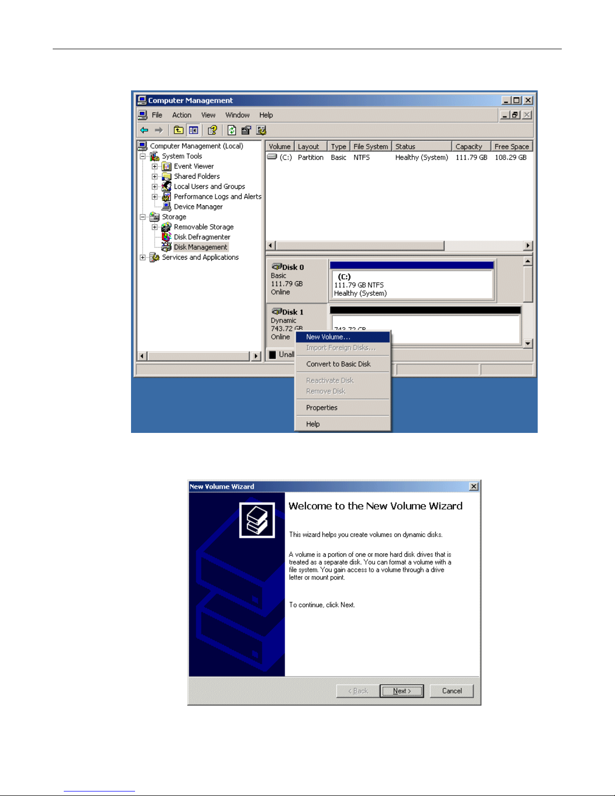
22) Now, right-click on the Disk 1 item in the lower-right-hand portion of the screen, and then select
the New Volume option from the ensuing pop-up menu as shown in Figure 3-27.
MaxPac Single/Dual/Triple-Screen 8230 Training and Maintenance Guide 15
Figure 3-27. Select the New Volume option
23) Observe the New Volume Wizard appear as shown in Figure 3-28.
Figure 3-28. The New Volume Wizard
16 MaxPac Single/Dual/Triple-Screen 8230 Training and Maintenance Guide
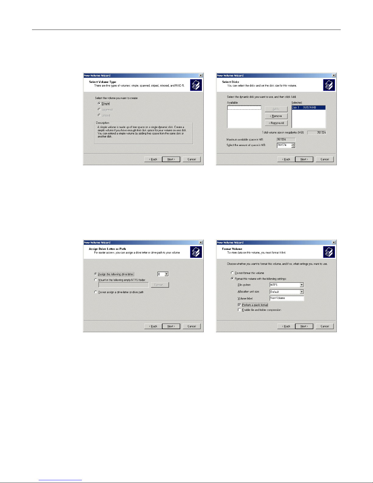
24) Click the Next button to be presented with the Select Volume Type screen. Click the Simple
option as shown in Figure 3-29.
Figure 3-29
Figure 3-30
25) Click the Next button to be presented with the Select Disk screen. Ensure that the Disk 1
item is selected and appears in the Selected column on the right-hand side of the dialog as
shown in Figure 3-30.
26) Click the Next button to be presented with the Assign Drive Letter or Path screen. Ensure
that the Assign the Following Drive Letter item is selected and accept the default letter
presented by the system (or enter a different letter if you require) as shown in Figure 3-31.
Figure 3-31
Figure 3-32
27) Click the Next button to be presented with the Format Volume screen. Click the Format this
volume with the following settings item as shown in Figure 3-32. Ensure that the settings
are File system = NTFS, Allocation unit size = Default, and Volume Label = user defined
(the default is "New Volume"). Also ensure that the Perform a quick format item is selected.
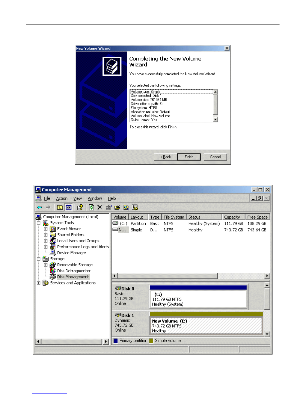
28) Click the Next button to be presented with the Completing the New Volume Wizard screen
as shown in Figure 3-33.
29) Click the Finish button to perform all of the operations and exit the wizard.
30) Observe that the Disk Management area of the Computer Management dialog now
shows Disk 1 as being Dynamic, Online, and Healthy as illustrated in Figure 3-34.
MaxPac Single/Dual/Triple-Screen 8230 Training and Maintenance Guide 17
Figure 3-33. The Completing the Wizard dialog
Figure 3-34. Disk 1 is now shown as being Dynamic, Online, and Healthy
18 MaxPac Single/Dual/Triple-Screen 8230 Training and Maintenance Guide
Rebuilding an Existing (Failed) 3ware RAID 5 Array
The discussions in this section assume that you originally have a good, working RAID 5 array. In this
case, if you double-click the Connect to 3DM 2 icon on your desktop and login to the ensuing
webpage using the default password (which is 3ware), you will see that the status of your array looks
something like that shown in Figure 3-35.
Figure 3-35
Once you have observed this good array, exit out of the 3DM 2 web interface. At some stage, one of
the disks in the array may start to degrade or go completely off-line. For the purposes of these
discussions, we are going to power down the system, physically remove Disk 01 from the array
(thereby simulating a catastrophic failure on this disk) and power up the system back up again.
1) Power down the system and remove the center data disk (Disk 01) as shown in Figure 3-36.
Figure 3-36
Figure 3-37
2) Power the system back up again. The BIOS detects the fact that there is a problem with the RAID
array and displays an appropriate message (Figure 3-37). Press the <Pause Break> key to freeze
the display; from this (and Figure 3-8) you will be able to determine which drive has failed.
3) Press and hold the soft power key in order to power the system down.
MaxPac Single/Dual/Triple-Screen 8230 Training and Maintenance Guide 19
4) Remove the failed drive and replace it with a good drive of the same type and capacity
(remember that we only removed the drive above in order to simulate a catastrophic failure
scenario).
5) Power the system up again all the way into windows.
6) Double-click the Connect to 3DM 2 icon on your desktop and login to the ensuing webpage
using your administrator password (note that you may need to contact your IT department in
order to obtain this password).
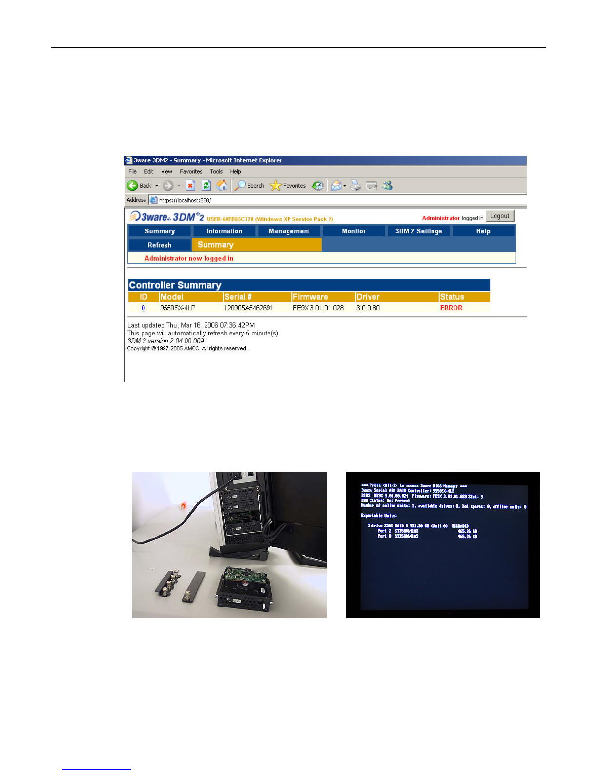
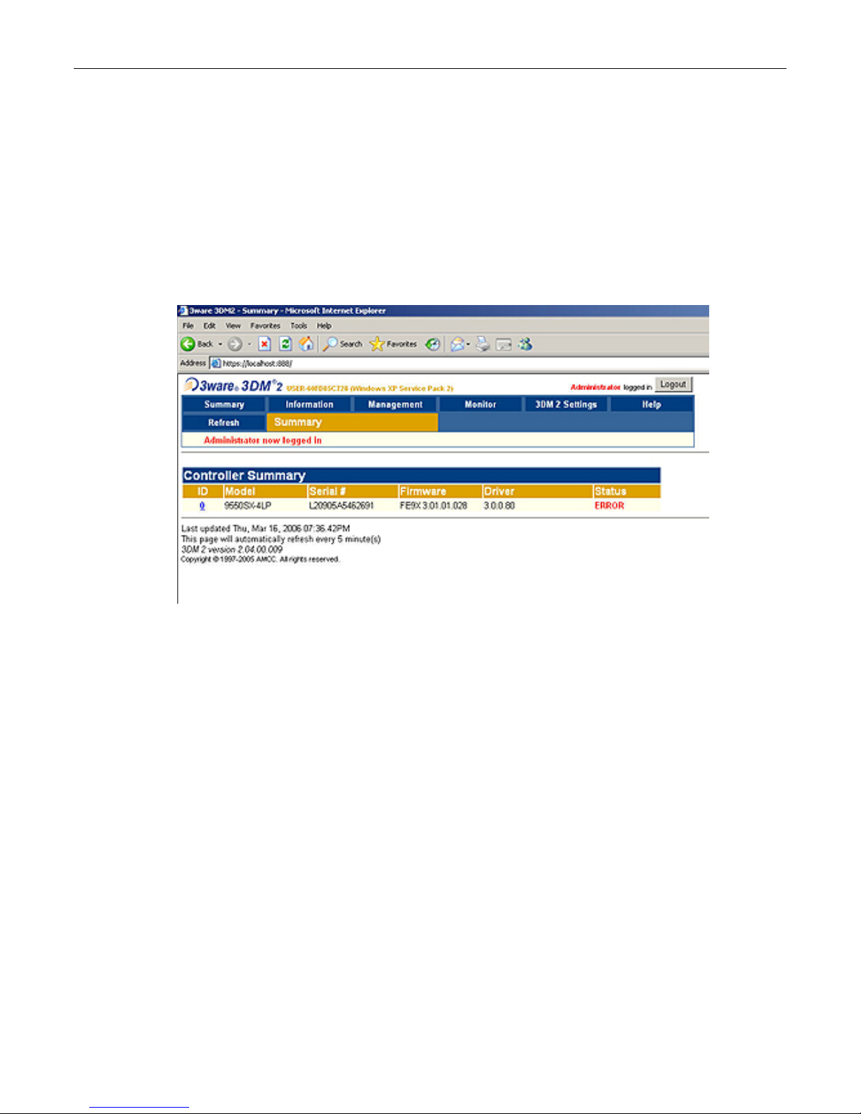
7) After you have logged in as the administrator, you will see a status of ERROR in the 3DM 2
interface (Figure 3-38).
Figure 3-38.
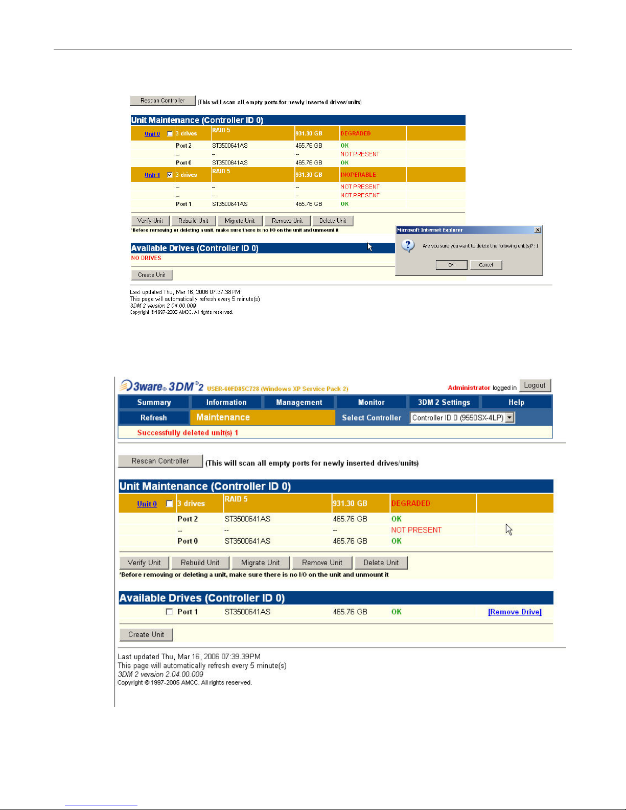
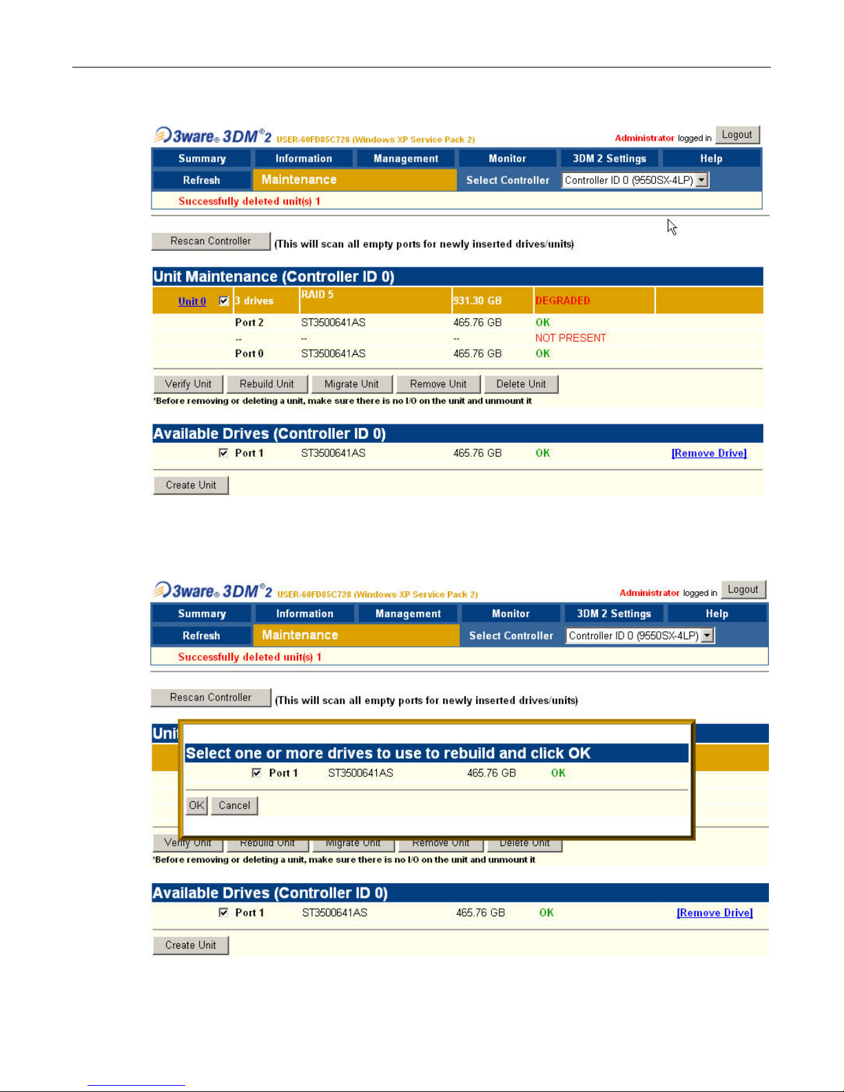
8) Observe that the system reports the two good drives as being in a DEGRADED unit as shown
in Figure 3-39.
9) Depending on the past history of the disk (whether or not it was previously part of a 3ware RAID
array) the system may report that the new disk is INOPERABLE as illustrated in Figure 3-39.
Alternatively, the system may report the new disk as being AVAILABLE as illustrated in Figure 3-40.
Assuming that the new disk is reported as being INOPERABLE, click the checkbox associated with
that unit (Unit 1 in this example) and then click the Delete Unit button. Observe that the system will
present you with a confirmation dialog as shown in Figure 3-39. Click the OK button, and observe
that the new disk is now reported as being AVAILABLE as illustrated in Figure 3-40.
10) Click the checkbox associated with the two good drives (shown as Unit 0 in this example) and also
click the checkbox associated the new replacement drive (shown as Port 1 in this example) and
then click the Rebuild Unit button associated with the two good drives as illustrated in Figure 3-41.
11) Observe the ensuing pop-up dialog box as shown in Figure 3-42. Click the checkbox associated
with the new drive, and then click the OK button.
20 MaxPac Single/Dual/Triple-Screen 8230 Training and Maintenance Guide
Figure 3-39.
Figure 3-40.
MaxPac Single/Dual/Triple-Screen 8230 Training and Maintenance Guide 21
Figure 3-41.
Figure 3-42.
22 MaxPac Single/Dual/Triple-Screen 8230 Training and Maintenance Guide
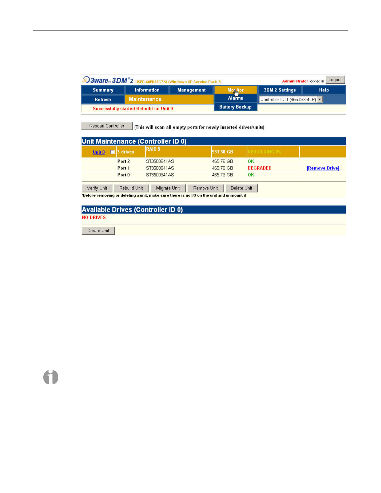
12) Observe that the replacement drive has now been incorporated into the RAID 5 array as
illustrated in Figure 3-43 (note that this array is still shown as being DEGRADED).
Figure 3-43.
When the new disk has been fully integrated into the array, the interface will reflect the
completion of the rebuild.
Note: This rebuild process can take a significant amount of time (14 hours in the case of our
example using 400 GB disks).
Note: The rebuild process is performed in the background, so you can continue to use your
system while the rebuild is taking place.
Configuring the RAID Array
(with Hot Spare and System Partition on RAID Array)
Note: Your MaxPac8230 may be configured for connection to the optional TeraPac3 8 drive SATA
Expansion. In this case the MaxPac8230 will include a 12 or 16 port SATA RAID 5 controller. This
chapter illustrates and assumes a 4 port SATA RAID 5 controller so the photos may be somewhat
different. Refer to Chapter 7 for a brief section on the MaxPac8230 connection to the TeraPac3 and
to the TeraPac3 User Operation and Maintenance Guide for more details.
Note that these discussions reflect system configurations that have the system partition established
on the RAID array itself (leaving a hot-spare drive) as illustrated in Figure 3-44. Configurations with a
separate system drive are discussed earlier in this chapter.
When you take possession of your MaxPac 8230 system, the RAID system will already have been
established, initialized, and verified. The instructions in this section are intended to address those rare
MaxPac Single/Dual/Triple-Screen 8230 Training and Maintenance Guide 23
situations where you need to replace a degraded/failed drive or you wish to rebuild the RAID system
from the ground up.
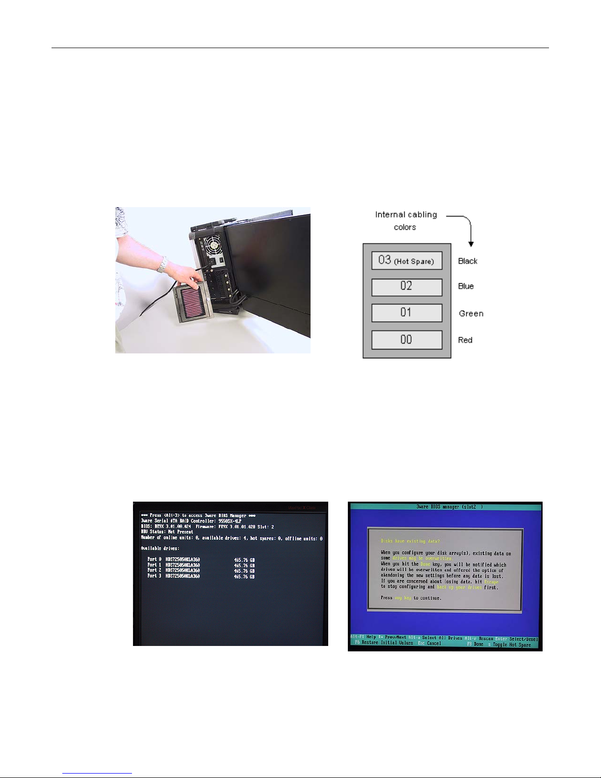
Your MaxPac system can contain up to four SATA hot-swappable hard disk drives presented in a
4-drive disk caddy. This caddy is located on the lower left-hand side of the main chassis under the
"Baghdad Filter" assembly as shown to the left of Figure 3-44 (the numbering of the disks is as shown
to the right of Figure 3-44). The main array – including the system partition – occupies disks 00, 01,
and 02, leaving disk 03 as the hot-spare (note that this is the initial/default configuration; once the hotspare disk has been deployed as discussed below, the failed-and-replaced disk will assume the role
of the new hot-spare).
Figure 3-44
Establishing the Array and Reloading the System Image
These discussions assume that you are reestablishing a system from the ground up, and that you
have four new disks in your disk caddy.
1) Start to power-up the system. When you see the BIOS message "<Alt-3> to access 3ware BIOS
Manager" (Figure 3-45) press and hold the <ALT> (alternate) key and – while still holding this key
– press the number "3" key. This will invoke the 3ware BIOS manager; in most cases, you will be
presented with a warning screen as shown in Figure 3-46.
2) Press any key to continue, which will take you fully into the 3ware BIOS Manager. Observe that
the four disks are shown on the screen, but no drives are initially selected (Figure 3-47).
Figure 3-45
Figure 3-46
24 MaxPac Single/Dual/Triple-Screen 8230 Training and Maintenance Guide
Figure 3-47
Figure 3-48
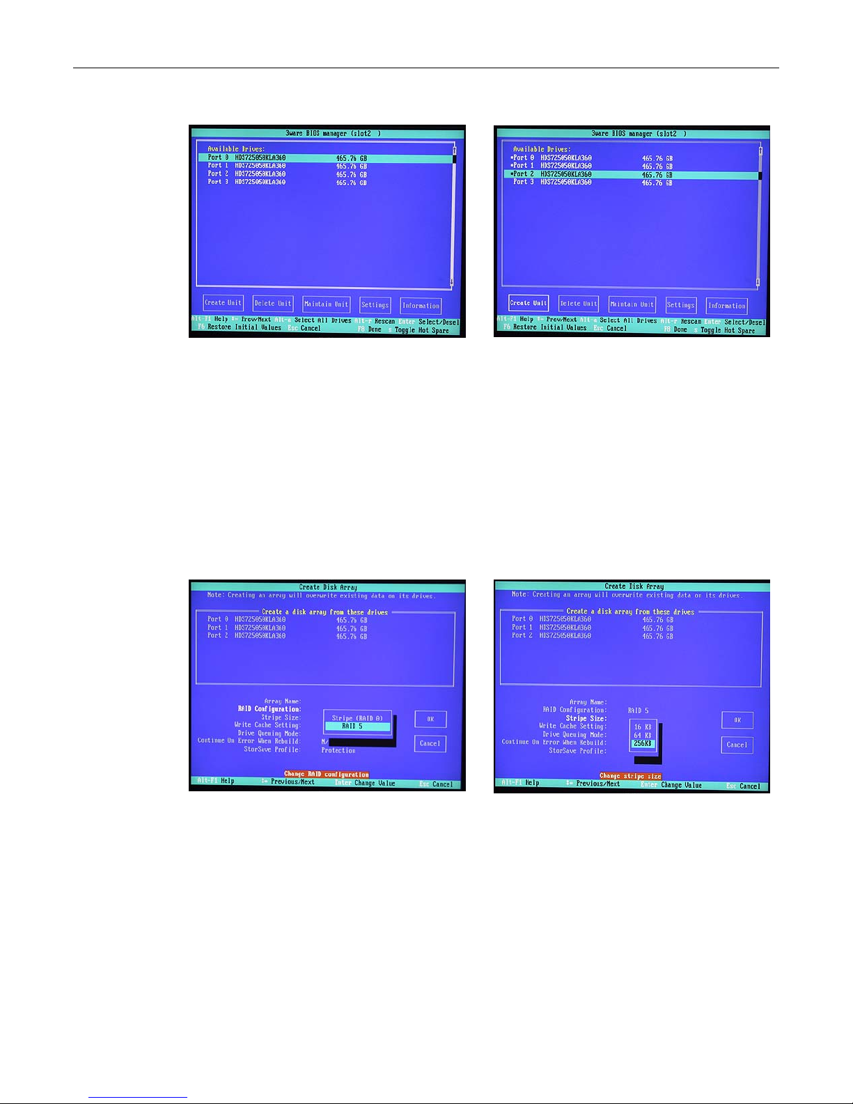
3) Use the up/down arrow keys to highlight disks 00, 01, and 02 in turn; as each disk is highlighted,
press the <Enter> key to select it (selected disks are indicated with an asterisk '*' character as
shown in Figure 3-48). (Note that the reason disk 03 is not selected is that this is being reserved
as the hot-spare.)
4) Use the <Tab> key to highlight the Create Unit option (Figure 3-48), then press the <Enter> key
to key to invoke the Create Disk Array screen.
5) Use the up/down arrow keys to highlight the RAID Configuration item, and then press the
<Enter> key to access an associated pop-up dialog (Figure 3-49).
6) Now use the up/down keys to highlight the RAID 5 option and then press the <Enter> key to
select this option.
7) Next, use the up/down arrow keys to highlight the Stripe Size item, and then press the <Enter>
key to access an associated pop-up dialog (Figure 3-50).
8) Use the up/down arrow keys to highlight the 256 KB option, and then press the <Enter> key to
select this option.
9) Use the up/down arrow keys to highlight the Write Cache Setting item, and then press the
<Enter> key to access an associated pop-up dialog (Figure 3-51).
10) Use the up/down arrow keys to highlight the Enabled option, and then press the <Enter> key to
select this option.
Figure 3-49
Figure 3-50
 Loading...