

Page 1
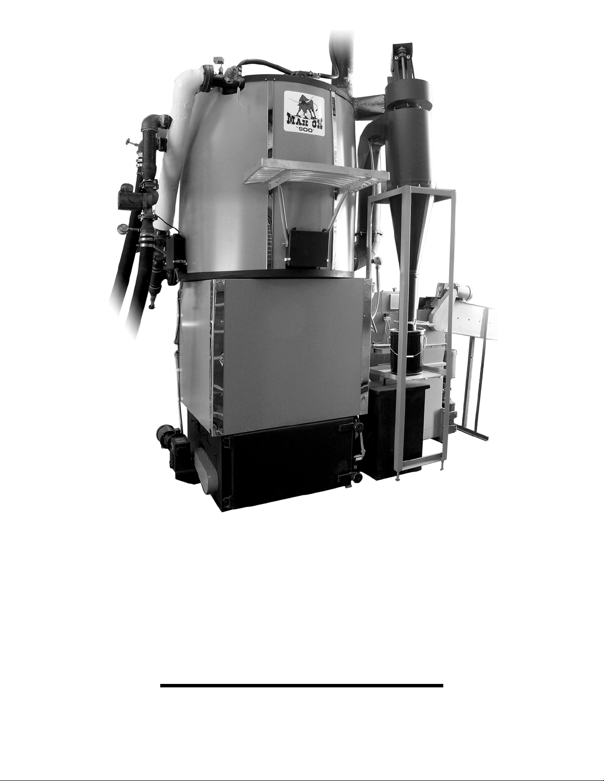
Max-Ox™ MX-900B
Commercial Wood Chip-Fired
Hydronic Boiler
Operators Manual
Max-Ox™ MX-900B Operators Manual, Rev. 0
Page 1 of 54
Page 2

Max-Ox™
Model MX-900B
Commercial Wood Chip-Fired
Hydronic Boiler
Operators Manual
Please include the Manual Issue shown below when
communicating with Technical Support regarding this publication.
Publication History
Issue Date Description of Changes
Rev. 0 2/09/09 Original
Max-Ox™ MX-900B Operators Manual, Rev. 0
Page 2 of 54
Page 3

Max Ox™ MX-900B Operators Manual
TABLE OF CONTENTS
Section ___Page
Manual Overview
Overview of this Publication 4
Who Should Read This Manual 4
Supplemental Publications 4
Codes and Insurance Notice 5
Technical Support 6
Warranty Registration 7
Limited Warranty 8
Special Symbols 13
Specifications 14
How it Works
An Overview 16
MX-900B Control System 16
Fuel In-Feed Conveyor (by Customer) 17
Fuel In-Feed System 17
Under-fire Stoker Grate 18
Secondary Combustion Chamber 19
Fire-Tube Hydronic Boiler 19
Exhaust Fan 20
Ash Removal 20
Wood Chips as Fuel 22
Safety Information 23
Installation 26
Operation – Start-up 28
Operation – Shut-down 32
Touch Screen Controls 33
Ash Cleaning 49
Routine Lubrication 51
Boiler Water Treatment Program 52
Fuel Feed Jam Clearing 52
Max-Ox™ MX-900B Operators Manual, Rev. 0
Page 3 of 54
Page 4

MX-900B Operators Manual
Overview of this Publication
Congratulations on your decision to make very efficient use of
precious renewable fuels by using a commercial-duty automated Max-Ox™
MX-900B Wood Chip-fired Hydronic Boiler.
This MX-900B Operators Manual describes the features, installation,
operation, and maintenance of your new Max-Ox™ MX-900B Commercial
Wood-chip Fired Hydronic Boiler.
Who Should Read This Manual
This manual contains important information for those who will install,
operate, or maintain the MX-900B Wood chip-fired Hydronic Boiler.
Supplemental Publications
The National Fire Protection Association (NFPA) publishes codes,
standards, recommended practices, and guidelines for the installation and
operation of solid fuel burning appliances. To help ensure safe installation of
the Max-Ox™ MX-900B, please refer to the following NFPA publications:
• NFPA 211: Standard for Chimneys, Fireplaces, Vents, and Solid Fuel
Burning Appliances, 2006 Edition.
For information on NFPA 211, and other related NFPA publications, please
contact:
National Fire Protection Association
1 Batterymarch Park
Quincy, MA 02169-7471
www.nfpa.org
Phone: 617-770-3000
Fax: 617-770-0700
Max-Ox™ MX-900B Operators Manual, Rev. 0
Page 4 of 54
Page 5

MX-900B Operators Manual
Codes and Insurance Notice
The Max-Ox™ MX-900B Commercial Wood-chip Fired Hydronic Boiler is
a mechanical draft, direct-vented, NON-PRESSURIZED VESSEL, solid
fuel burning appliance. It must be installed in accordance with this Manual,
NFPA 211, Federal, State, and Local codes, and your Insurance
Underwriter’s requirements.
Local building code enforcement officials and fire inspectors are given
authority to determine if specific installations of solid fuel burning
appliances are safe. These professionals use recommended guidelines from
various nationally recognized organizations, such as the National Fire
Protection Association (NFPA), and the National Electrical Manufacturer’s
Association (NEMA).
Please be sure to follow the requirements of the Authority Having
Jurisdiction over your specific installation.
Your Insurance Underwriter may also have specific guidelines with respect
to installation and inspection requirements for your solid fuel burning
appliance.
Max-Ox™ MX-900B Operators Manual, Rev. 0
Page 5 of 54
Page 6

MX-900B Operators Manual
Max-Ox™ Technical Support
Your Sales Representative is your authorized Max-Ox™ factory -
trained Technical Support team member, and is standing-by to answer any
questions you may have with respect to your Max-Ox™ MX-900B
Commercial Wood-chip Fired Hydronic Boiler.
Please record the model number and serial number of your Max-Ox™
MX-900B in the space provided, and have this information available when
contacting your factory-authorized Sales Representative:
Model number: ________________ Serial Number: ________________
Operators Manual Revision Number: ________________
Purchase Date: ________________
Installation Date: ______________
Max-Ox™ MX-900B Operators Manual, Rev. 0
Page 6 of 54
Page 7

Max-Ox™ Warranty Registration Form
All Max-Ox™ products must be registered to activate the warranty,
and we encourage you to send this registration form back to us within 10
days of installation.
Please mail or fax the completed Max-Ox™ Warranty Registration
Form to:
Max-Ox, LLC Fax: (717) 464-0491
Mail: Max-Ox, LLC
481 Millwood Road
Willow Street, PA 17584
Customer Name: _______________________________________________
Address: _____________________________________________________
_____________________________________________________
_____________________________________________________
Phone: _________________________Fax: __________________________
E-mail: _______________________________________________________
Sales Representative Name: ______________________________________
Model Number: ___________________ Serial Number: ________________
Installation Date: _______________________________________________
Customer Signature: ____________________________________________
Date: ________________________________________________________
Max-Ox™ MX-900B Operators Manual, Rev. 0
Page 7 of 54
Page 8

Certificate of Limited Warranty
Max-Ox™ Wood Chip-Fired Hydronic Boilers
Page 1 of 5
General
This Limited Warranty is only available to the original owner of this
Max-Ox™ Wood-chip fired Hydronic Boiler (Unit). It is not transferable.
Max-Ox, LLC (Max-Ox) warrants this Max-Ox™ Wood-chip fired
Hydronic Boiler, and its component part(s), to be free from defects in
materials and workmanship, under normal use and service, for the
Applicable Warranty Periods. At its option, Max-Ox will repair or replace
defective Max-Ox™ Wood-chip fired Hydronic Boiler, or defective
component part(s), in accordance with the terms of the Limited Warranty, if
it fails in normal use and service during the Applicable Warranty Periods..
Any replacement components or replacement part(s) must be Max-Ox
authorized component or part(s). The replacement unit or part(s) will be
warranted only for the unexpired portion of the Unit’s Applicable Warranty
Periods.
Effective Date:
The Effective Date of the commencement of warranty coverage (or
the beginning of the Applicable Warranty Periods) is the date of installation
of the Unit, provided the installation, operation, and maintenance of the Unit
conforms to the instructions in the Max-Ox™ MX-900B Operators Manual,
applicable Federal, State, and Local codes, Customer’s Insurance
Underwriter requirements, and good plumbing, electrical, and HVAC
(Heating, Ventilation, Air Conditioning) trade practices. Otherwise, the
Effective Date of the commencement of warranty coverage is the date of the
manufacture of the Unit plus ninety (90) days.
Applicable Warranty Periods
Whetted hydronic heat exchanger components: Three (3) years
Cast refractory on stoker doors and combustion chamber: Three (3) years
Steel fabrications, mechanical components, thermal insulation: One (1) year
Electrical, electro-mechanical, and electronic components: One (1) year
Plumbing components (pump, valves, fittings, maifolds): One (1) year
Max-Ox™ MX-900B Operators Manual, Rev. 0
Page 8 of 54
Page 9

Certificate of Limited Warranty
Max-Ox™ Wood Chip-Fired Hydronic Boilers
Page 2 of 5
Applicable Warranty Periods (continued)
During the Applicable Warranty Periods, Max-Ox will pay a pro-rated
share of the cost of a defective item. For example, in the first year Max-Ox
will pay 100% of the cost of any failed item; in the second year Max-Ox will
pay 100% less 33.3% of the whetted hydronic heat exchanger components
and cast refractory components (3 year pro-rated); and so on until the end of
the Applicable Warranty Periods.
Warranty Exclusions
This Limited Warranty will not cover:
1. Damages to the fuel in-feed system components or fuel feed auger
train components or ash auger train components or stoker head
assembly components caused by non-wood materials present in the
fuel that are large enough to result in jams, such as metals, rocks,
masonry, fabrics, rope, stringy plant fibers.
2. Damages to the fuel in-feed system components or fuel feed auger
train components or ash auger train components or stoker head
assembly components caused by materials other than approved fuels.
Approved Fuels are specified as follows:
a. wood chips < 1.5” maximum dimension
b. wood dust briquettes < 2” maximum dimension
c. wood shavings
d. wood construction / demolition waste < 1.5” maximum dim.
3. Whetted hydronic heat exchanger component leak failure due to
contaminated or corrosive water-based heat transfer fluid or make-up
water.
4. Whetted hydronic heat exchanger component leak failures due to
Customer’s failure to follow a bi-annual (every 6 months) commercial
boiler water chemistry program for boiler water chemical analysis,
chemical treatment, boiler water blow-down, and boiler water make-
Max-Ox™ MX-900B Operators Manual, Rev. 0
Page 9 of 54
Page 10

up water addition for an open-system (non-pressurized) hydronic
heating boiler.
Certificate of Limited Warranty
Max-Ox™ Wood Chip-Fired Hydronic Boilers
Page 3 of 5
Warranty Exclusions (continued)
5. Service trips to your facility for instruction on how to install, operate,
or maintain the Unit, or to bring the Unit into compliance with local
codes or insurance underwriter requirements.
6. Units removed from the original installation location.
7. Damages, malfunctions, or failures resulting from failure to install the
Unit per applicable codes, or good plumbing, electrical, or HVAC
trade practices.
8. Damages, malfunctions, or failures resulting from failure to install,
operate, or maintain the Unit in accordance with the Max-Ox™ MX900B Operators Manual.
9. Damages, malfunctions, or failures resulting from over-firing the Unit
on combustible materials other than Approved Fuels.
10. Damages, malfunctions, or failures caused by abuse, accident, fire,
flood, freezing, lightning, or acts of God.
11. Damages, malfunctions, or failures resulting from failure to operate
the Unit without sufficient heat transfer fluid.
12. Cracks in the cast refractory that can be repaired with high-
temperature refractory joint compound.
13. Performance problems caused by improper sizing of the Unit,
improper sizing of the flue gas vent, or improper sizing of the
combustion make-up air opening requirements.
Labor, Shipping, and Processing Costs
This Limited Warranty does not cover any labor expenses for service,
repairs, reinstallation, permits, or removal and disposal of a failed Unit or its
defective component part(s). All such expenses are the owner’s
responsibility.
Max-Ox™ MX-900B Operators Manual, Rev. 0
Page 10 of 54
Page 11

Certificate of Limited Warranty
Max-Ox™ Wood Chip-Fired Hydronic Boilers
Page 4 of 5
Labor, Shipping, and Processing Costs (continued)
Max-Ox, LLC will pay for delivery of an “in-warranty” replacement
Unit or component part(s) to a location at or near the original point of
delivery. The Owner is responsible for any additional local delivery,
equipment rigging, and reinstallation charges. The owner is also responsible
for freight costs incurred in the return of a defective Unit or component
part(s) to the point of purchase.
Activation of Warranty
All Max-Ox™ products must be registered to activate the warranty,
and we encourage you to send this registration form back to us within 10
days of installation. The Warranty Registration Form is located on page 7 of
this manual.
Please mail or fax the completed Max-Ox™ Warranty Registration
Form to:
Max-Ox, LLC; fax: (717) 464-0491
Mail: Max-Ox, LLC
481 Millwood Road
Willow Street, PA 17584
How to Obtain Warranty Claim Assistance
Max-Ox™ MX-900B Operators Manual, Rev. 0
Page 11 of 54
Page 12

Warranty Claims must be made promptly to your factory authorized
Sales Representative. Your Sales Representative will assist you through the
claim process with costs apportioned as described elsewhere in this Limited
Warranty.
Certificate of Limited Warranty
Max-Ox™ Wood Chip-Fired Hydronic Boilers
Page 5 of 5
How to Obtain Warranty Claim Assistance (continued)
Max-Ox, LLC reserves the right to inspect, or require the return of, a
failed Unit for defective part(s). If requested items are not returned, or are
returned without all of the component parts intact, Max-Ox, LLC reserves
the right to invoice the Owner for the replacement Unit or part(s).
Exclusive Warranty – Limitation of Liability
This Limited Warranty is the only Warranty for this Unit given by
Max-Ox, LLC. No one is authorized to make any other warranties for the
Unit or its component part(s) on behalf of Max-Ox, LLC.
ANY IMPLIED WARRANTIES, INCLUDING
MERCHANTABILITY, FOR FITNESS FOR A PARTICULAR PURPOSE,
SHALL NOT EXTEND BEYOND THE APPLICABLE WARRANTY
PERIODS. THE SOLE LIABILITY OF MAX-OX, LLC, WITH RESPECT
TO ANY DEFECT, SHALL BE AS SET FORTH IN THIS LIMITED
WARANTY, AND ANY CLAIMS FOR INCIDENTAL OR
CONSEQUENTIAL DAMAGES (INCLUDING DAMAGE FROM
WATER LEAKAGE) ARE EXCLUDED. Some states do not allow
limitations on how long an implied warranty lasts, or for the exclusion of
incidental or consequential damages, so the above limitations or exclusions
may not apply to you.
This Limited Warranty gives you specific legal rights, which vary
from state to state.
Max-Ox™ MX-900B Operators Manual, Rev. 0
Page 12 of 54
Page 13
MX-900B Operators Manual
Special Symbols
Note the use of signal words: DANGER, WARNING, and
CAUTION with safety messages. The appropriate Signal Word
has been selected using the following guidelines:
DANGER: Indicates an imminently hazardous situation which, if
not avoided, will result in death or serious injury.
WARNING: Indicates a potentially hazardous situation which, if
not avoided, will result in death or serious injury.
CAUTION: Indicates a potentially hazardous situation which, if not
avoided, may result in minor or moderate injury, or serves as a reminder
to follow appropriate safety practices.
Max-Ox™ MX-900B Operators Manual, Rev. 0
Page 13 of 54
Page 14

Max-Ox™ MX-900B Operators Manual, Rev. 0
Page 14 of 54
Page 15

MX-900B Operators Manual
Specifications
Your new Max-Ox™ MX-900B is classified as a fully modulated
(automatic), induced draft, under-grate stoker fed wood chip-fired hydronic
heating (hot water) boiler.
a. Nominal Output, BTU/hr: 900,000
b. Design Supply Temperature: 180°F
c. Approved Fuels:
o wood chips < 1.5” maximum dimension
o wood dust briquettes < 2” maximum dimension
o wood shavings
o wood construction / demolition waste < 1.5”
maximum dimension
d. Heat exchanger type: 2-pass fire tube type (non-condensing)
e. Material: Carbon Steel per ASTM A-36
f. Heat transfer fluid: water
g. Working pressure: 0 psig (atmospheric, NON-PRESSURIZED)
h. Design Supply temperature: 180 °F
i. Modulated (variable) speed primary loop circulator
j. Heat Transfer Fluid Capacity: 300 gallons
k. Fluid Temperature Control: PLC
l. Supply & Return connections: 3 inch female NPT
m. Draft type: Induced draft
n. Flue gas stack outlet diameter: 8 inches
o. Ash Clean-out: full-access top removable panels, (3) exhaust
plenum doors, ash cyclone container, ash auger bin, front and
rear stoker head access doors, bolted stoker grate access panel
p. Thermal insulation envelope: full coverage mineral wool
blanket on heat exchanger and combustion section, cast
refractory on stoker head doors and secondary combustion
section..
q. Enclosure: non-weather-tight primed and painted steel
r. Dimensions: 6 ft. wide x 14 ft long ( includes metering bin and
fuel auger) x 10 ft-6 inch to top of boiler
s. Weather enclosure ceiling height for boiler top panel removal:
14 feet
Max-Ox™ MX-900B Operators Manual, Rev. 0
Page 15 of 54
Page 16

MX-900B Operators Manual
Specifications (cont)
t. Electrical Requirements: 30 Amp, 240 VAC, 1 phase, 3-wire
plus safety ground
Operating current: 8 Amps
u.
v. Auxiliary control dry contacts
w. Combustion turn-down ratio: 8:1
x. Fuel Auger Tube Fire Extinguisher Water connection: _ female
y. Dry (shipping & rigging) weight: 7,800 lbs
1. Boiler Ready signal contact
2. System Alarm signal contact
3. Fuel In-Feed conveyor control contact
4. Heat Dump control contact
NPT, 1/2 inch minimum supply pipe diameter @ 40 psi
minimum water pressure
Max-Ox™ MX-900B Operators Manual, Rev. 0
Page 16 of 54
Page 17

MX-900B Operators Manual
How it Works
An Overview
Your new MX-900B Wood chip-fired Hydronic Boiler (hot water
heating boiler) is a very modern version of a very old and time-proven
method for properly burning solid fuels; called the “under-fire stoker
grate” method.
What sets your MX-900B system apart from previous older
generations of under-fire stoker grate systems is that the MX-900B
system makes use of modern advances in controls technology and
knowledge of combustion chemistry, along with advances in materials
science and modern manufacturing methods, to provide you with a
rugged, highly fuel efficient and low maintenance automatic wood
chip-fired combustion system.
This How it Works narrative is written to guide you through each
functional sub-assembly of the MX-900B Combustion System, so that
you will gain a clear understanding of the entire unit.
MX- 900B Control System:
The automatic control system of the MX-900B system is a modern
version of proven combustion control strategy. The MX-900B Control
System hardware consists of an industrial-duty programmable logic
controller (microprocessor-based PLC), touch-screen Operator
interface control / view panel, three variable speed AC motor
controllers, and a very carefully selected array of robust automation
sensors.
These industrial-duty controls components are orchestrated in unison
through a carefully designed, and extensively field tested, set of
software programs that are permanently stored in the memory of the
programmable logic controller. The control system is designed to
ensure safe operating conditions are maintained at all times, and to
initiate an automatic shut-down in the event of a fault.
Max-Ox™ MX-900B Operators Manual, Rev. 0
Page 17 of 54
Page 18

Fuel In-Feed System Conveyor ( by Customer):
You will need to provide wood chip fuel in-feed conveyor system in
order to supply fuel to your MX-900B unit. Your fuel in-feed system
should be tailored to your specific site layout requirements.
We recommend that your fuel storage bin or silo be designed to
protect your wood chips from the weather. Your wood chip transfer
conveyor should be designed to transport fuel from your storage
bin/silo to the MX-900B Fuel Metering Bin.
1. Sizing your Transfer Conveyor: Your transfer conveyor system
should be sized to convey approximately _ to 1 cubic yards of
wood chips per hour in order to support the maximum fuel
firing rate of the Max-Ox unit. This fuel flow rate criteria is a
conservative estimate that takes into account the additional fuel
volume flow needed when firing green (fresh-cut) hardwood
wood chips, as well as the variations in bulk density (fluffiness)
of the chipped or shredded wood fuel types available. Of
course, the dryer your fuel is, the less of it you will need to burn
to achieve the full power rating of renewable fuel combustion
units.
Fuel In-Feed System:
Your MX-900B mechanical hardware begins at the fuel in-feed
system. The fuel in-feed system serves to automatically receive wood
chips from your fuel storage and transfer system, and then deliver
them to the stoker grate combustion unit. The fuel in-feed system
consists of an inlet chute, an air operated knife gate, a small auxiliary
electric air compressor, a small storage chamber called the metering
bin, a fuel in-feed auger with variable speed drive motor, and a set of
automatically controlled electrical contacts to energize your fuel infeed conveyor motor controller.
Inlet Chute, Knife Gate, Metering Bin, and Air Compressor:
The fuel in-feed system inlet chute serves to funnel wood chips
through an open knife gate, and into the metering bin. A level sensor
in the metering bin signals your fuel transfer conveyor to stop, and
Max-Ox™ MX-900B Operators Manual, Rev. 0
Page 18 of 54
Page 19

closes the knife gate. The auxiliary air compressor provides
compressed air for actuation of the knife gate.
Fuel Feed Auger and Drive Motor: Wood chip fuel is fed by a
rotating helical auger from the metering bin and on into the stoker
grate combustion unit. The fuel feed auger is located in the bottom of
the metering bin, and extends into the stoker grate combustion unit.
The variable speed electric motor and gear reduction assembly that
drives the auger is equipped with an automatic jam clearing feature to
protect your system in the event your fuel inadvertently becomes
contaminated with unwanted metals or stones that cause the auger to
jam.
Fuel Feed Tube Fire Extinguisher: The fuel feed tube between
the metering bin and the stoker is equipped with a thermostatically
actuated water valve and thermostatic sensing element. Should the
temperature of the fuel within the fuel feed tube increase to 150 °F,
water will begin to spray into the fuel feed tube to extinguish any fire
that may be present. Below 150°F the fire extinguisher valve is fully
closed, and at a set-point of 190°F the valve is fully open.
Under-fire Stoker Grate:
An under-fire stoker grate combustion system is a simple time-proven
and robust method for conveying solid fuels into a combustion
chamber. Wood chips are conveyed by a rotating helical fuel in-feed
auger from the fuel in-feed metering bin and on into the stoker unit.
Fuel gently spills out of the mouth of the stoker cavity, and onto a
stationary ring-shaped grate. Very thin slots in the ring grate permit preheated fresh combustion air to permeate the fuel bed that has spilled
onto the top of the ring grate, and thereby sustain a steady fire on the
exposed surface of the fuel.
Combustion Air Adjustment: Three manually adjustable
combustion air slide gates are mounted on the exterior face of the
stoker grate assembly. One slide gate serves to manually adjust and
set the Primary combustion air flow rate up through the thin slots in
the stoker ring grate. A second slide gate serves to manually adjust
and set the Secondary combustion air flow rate into the Secondary
Combustion Chamber lower combustion air inlets. A third slide gate
Max-Ox™ MX-900B Operators Manual, Rev. 0
Page 19 of 54
Page 20

serves to manually adjust and set the Tertiary combustion air flow rate
into the Secondary Combustion Chamber upper combustion air inlets.
Secondary Combustion Chamber:
All of the hot gases rising off of the burning surface of the fuel rise
upward into a well-insulated but extremely hot ceramic-lined secondary
combustion chamber. Carefully proportioned and highly preheated
secondary combustion air is introduced into the rising flammable fuel
gases within the secondary combustion chamber in such a way as to
promote thorough mixing with the rising fuel gasses. The resultant
mixture produces very high combustion temperatures, and therefore
very complete combustion.
Fire-Tube Hydronic Boiler:
All of the very high temperature fully combusted gasses continue to
flow upward into a modern, high efficiency, 2-pass hydronic heat
exchanger, wherein all of the available heat energy is extracted, without
permitting water vapor in the flue gas to condense. Heat energy is
transferred to circulating water for your hydronic space heating or
industrial /commercial process hot water needs.
Heat Exchangers and Water Vapor: The Hot Water Heating Boiler
system flue gas exhaust temperature and the boiler return temperature
are automatically controlled so as to prevent condensation of water
vapor within the heat exchanger. This means that just enough heat
energy deliberately remains in the exhaust gases so that the water vapor
does not cool down to the point where liquid water forms within the
heat exchangers, or your chimney. Instead, the water remains in the
vapor state, and is exhausted into the atmosphere. On cool days you
will see this water vapor form a vapor cloud plume as the exhaust rises
up into the atmosphere.
Max-Ox™ MX-900B Operators Manual, Rev. 0
Page 20 of 54
Page 21

Exhaust Fan (Induced Draft):
A variable speed exhaust fan, referred to as an “Induced Draft” fan, is
mounted on the exhaust connection of your heat exchanger. This
variable-speed electric fan serves to pull fresh combustion air through
both the primary and secondary combustion air pre-heater sections, and
into the combustion chambers, pulls all combustion gases through the
combustion chambers and heat exchanger, pulls particulate laden flue
gas through a high efficiency cyclone dust collector, and then pushes
the combustion exhaust gasses (including water vapor) up the chimney
and out into the atmosphere.
Ash Removal:
As a solid fuel, wood is perhaps the best renewable fuel on the planet
from a “minimum ash content” perspective because wood has less than
1% ash content by weight (example: Oak = 0.15% ash by weight). For
the sake of comparison, coal mined in the United States ranges from 5%
to 20% ash by weight. When compared to coal ash, wood ash is much
more soft, fine, and fragile, and as such becomes airborne more easily.
Your MX-900B ash removal system has been designed to address wood
ash removal as follows:
Rotating Ash Ring, Ash Plow, Ash Auger & Ash Bin: The burning
surface of the fuel bed situated on top of the ring grate converts the
resinous lignin (sap) and solid fixed-carbon in the wood into flammable
gases, leaving behind non-combustible minerals as “ash”. As fresh fuel
is pushed out of the center of the stoker mouth and onto the ring grate,
the ash which has formed around the perimeter of the burning pile is
pushed further out-board away from the ring grate, and onto a slowly
rotating solid ring, called the “ash ring”.
Ash Plow: a fixed-position diagonal plow blade located above the
rotating ash ring scrapes ash material into an ash trough as the
ash ring rotates beneath the plough.
Ash Auger: A variable speed, motor-driven ash auger, situated in
a trough located out-board and slightly below the rotating ash
ring, receives ash scraped off of the ash ring by the plough. The
Max-Ox™ MX-900B Operators Manual, Rev. 0
Page 21 of 54
Page 22

ash auger rotates slowly to transport ash out of the combustor
stoker assembly, and into a covered ash bin. Both the rotating
ash ring and the ash auger are driven by the same variable-
speed electric motor and reduction gear assembly.
Ash Bin: A covered ash bin, located out-side of and adjacent to the
stoker assembly, serves to receive the ash from the ash auger.
The ash bin cover is removable, and the ash bin is detachable
and removable from the ash auger assembly. The ash bin is
manually emptied when 75% full of ash.
Hydronic Boiler Ash Clean-out Doors: The hydronic boiler is equipped
with three lower exhaust plenum ash clean-out doors, and four upper
ash clean-out panels to access boiler tubes. The lower ash clean-out
doors are insulated, hinged, and latched assemblies that permit removal
of fly ash that has accumulated in the boiler exhaust gas plenum. Four
insulated and clamped removable upper ash clean-out / boiler tube
access panels are situated on top of the boiler. The four upper panels
permit removal of fly ash that has accumulated in the upper boiler
exhaust gas reversal plenum, as well as provide access to the heat
exchanger tubes and removable fire-tube turbulators for cleaning during
routine maintenance.
Stoker Clean-out Doors: The stoker unit is equipped with two hinged,
latched and insulated clean-out doors that permit removal of fly ash that
has accumulated in the stoker unit. Ash removal from this region is
performed infrequently during routine maintenance.
Removable Stoker Grate: The slotted ring-shaped stoker grate is built
as four removable circular segments, so that any fine mineral or sand
particles present in the fuel that have fallen into the primary combustion
air chamber beneath the stoker grate can be cleaned out during routine
maintenance.
Stoker Grate Access Panel: The stoker grate assembly is fitted with a
bolted and removable ash clean-out access panel, which is removed for
ash clean-out access during routine maintenance.
Particulate Cyclone: Coupled to the boiler is a high efficiency
particulate cyclone dust collector designed to remove fly ash from the
Max-Ox™ MX-900B Operators Manual, Rev. 0
Page 22 of 54
Page 23

flue gas prior to discharge of the gas up the exhaust stack. The conical
section of the cyclone is equipped with an isolation damper and a sealed
ash collection container. The container is removed and emptied during
routine maintenance.
Wood Chips as a Fuel:
Your MX-900B Combustion System has been designed for, and is
approved for, the efficient combustion of dry wood chips, green (freshcut) wood chips, hogged (shredded) dry wood, hogged (shredded) green
(fresh-cut) wood, and shredded wood construction demolition waste
(tramp metal removed), for all species of wood.
Fuel Contaminants – Metals & Stones: The fuel in-feed auger and
the ash auger are stout and robust in design and construction. Also,
the fuel in-feed auger is equipped with an automatic jam-clearing
feature. However, there is a practical limit as to how much tramp
metal or stone a mechanical auger will tolerate. Therefore, we
advise that you take care to ensure that your fuel supply is as free
of these contaminants as possible.
Wet Fuel Economics: We recommend that you avoid un-necessary
water in your wood-chip fuel. As a general rule, the amount of
recoverable (available-for-use) heat energy from green (fresh-cut)
or hardwood chip fuel is less than half of what could have been
recovered had the wood chips been allowed to air dry naturally,
and then protected from the weather.
Wet Fuel = Increased Fuel Use: Your MX-900B system will
properly burn green (fresh-cut) wood chips very well, and has been
intentionally designed and tested for this type of fuel.
Unfortunately, as is the case for any type of combustion system, be
it fossil fuel-fired or a biomass fuel-fired, the high amount of heat
stored in the exhaust gas water vapor is significant. When possible,
we advise that you avoid any unnecessary additional water in your
fuel because of the increased fuel consumption needed to
evaporate the water.
Max-Ox™ MX-900B Operators Manual, Rev. 0
Page 23 of 54
Page 24

Safety Information
Safety Precautions
Use only those fuels listed in the Introduction and Specifications
section. Use of un-approved fuels may void your warranty. Please
see the warranty section of this manual for specific limitations with
respect to approved fuel types.
For approval to use fuels other than those listed in this manual,
please contact your Authorized Max-Ox Sales Representative.
Use of fuels other than those approved in this manual, or in writing
by the Max-Ox Company, may create a fire hazard or safety
hazard, and may void your warranty.
Do not use gasoline, naptha,, lighter fluid, fuel oil, engine oil, or
other any other flammable liquid or petroleum product in, on, or
near MX-900B Units..
Operate Max-Ox™ MX-900B Units at atmospheric pressure only.
Keep the vent cap loose on the vent opening. Do not seal or clamp
down on the vent cap.
Keep the area around MX-900B Boilers clear of combustible
materials to avoid a fire hazard.
Ashes must be contained in a non-combustible container with a
tight-fitting lid.
Observe the Required Clearances to Combustible Surfaces as
specified in National Fire Protection Association 211, Standard for
Chimneys, Fireplaces, Vents, and Solid Fuel-Burning Appliances,
for installation of MX-900B, as well as for installation of fuel
storage containers, bins, silos, and fuel transfer conveyor
equipment, and for installation of, or connection to chimney
connectors and/or chimney systems.
Max-Ox™ MX-900B Operators Manual, Rev. 0
Page 24 of 54
Page 25
When inspecting the stoker-grate combustion chamber, open the
door slowly.
Be sure to review all safety information in this manual prior to
operating the unit.
Please contact your Authorize Sales Representative if you have
questions that are not covered in this manual.
Safety Alert Symbol
The Safety Alert symbol identifies important safety messages in the
manual. This symbol indicates the possibility of injury or death.
Follow all instructions in the safety message given. This symbol
means “attention”, “be alert”, and “your safety is involved”.
Maintenance Safety
Electrocution Hazard. Disconnect and lock-out / tag-out the
electrical power supply to the Max-Ox™ 900B, prior to
performing any service or maintenance.
Do Not Operate the MX- 900B without all safety guards in place,
and all doors closed and latched..
Max-Ox™ MX-900B Operators Manual, Rev. 0
Page 25 of 54
Page 26

Fire Hazard. Ash and/or residue may ignite outside of the
combustion chamber. In the event of a fire:
• Press Emergency Stop Button
• Use Fire Extinguisher to contain fire
• Contact your local Fire Department
Fire Hazard. Collect ashes in a non-combustible container with a
tight-fitting lid. Do not place waste other than ashes in same
container.
Surfaces may be Hot! Please wear full coverage protective
clothing , shoes, leather gloves, and safety glasses when
performing routine maintenance on your MX-900B.
Max-Ox™ MX-900B Operators Manual, Rev. 0
Page 26 of 54
Page 27

Installation
The Max-Ox™ MX-900B Commercial Wood-chip Fired Hydronic Boiler is
a mechanical draft, direct-vented, NON-PRESSURIZED VESSEL, solid
fuel burning appliance. It must be installed in accordance with this Manual,
NFPA 211, Federal, State, and Local codes, and your Insurance
Underwriter’s requirements.
Local building code enforcement officials and fire inspectors are given
authority to determine if specific installations of solid fuel burning
appliances are safe. These professionals use recommended guidelines from
various nationally recognized organizations, such as the National Fire
Protection Association (NFPA), and the National Electrical Manufacturer’s
Association (NEMA).
Please be sure to follow the requirements of the Authority Having
Jurisdiction over your specific installation.
Your Insurance Underwriter may also have specific guidelines with respect
to installation and inspection requirements for your solid fuel burning
appliance.
The Max-Ox™ MX-900B must be installed per the requirements of National
Fire Protection Association (NFPA) 211: Standard for Chimneys, Fireplaces,
Vents, and Solid Fuel Burning Appliances, 2006 Edition.
Minimum horizontal clearance from combustible materials must be 48
inches in order to permit access door operations during routine maintenance.
Where permissible, additional horizontal clearance is desirable for ease of
maintenance access.
Minimum clearance from the top of the hot water heating boiler to a
combustible ceiling shall be no less than 36 inches. Additional vertical
clearance is desirable, where possible, for ease of maintenance access.
The MX-900B must be placed on a non-combustible concrete surface
designed to support the 7,800 pound shipping weight of the unit, plus an
additional 2,500 pounds for the heat transfer fluid in the hot water heating
boiler.
Max-Ox™ MX-900B Operators Manual, Rev. 0
Page 27 of 54
Page 28

The MX-900B must be shimmed level and plumb during installation.
All aspects of installation shall conform to good plumbing, electrical, or
HVAC trade practices.
Proper pump(s) and piping sizing is the responsibility of your qualified
installer.
The Max-Ox™ MX-900B is an open system NON-PRESSURIZED
hydronic Boiler. DO NOT PRESSURIZE.
An open (vented) expansion tank must be incorporated into the system in
order to maintain the heat exchanger (boiler) full of water at all times, and to
prevent pressurization. No valve or restriction is permissible in the pipe
connecting the heat exchanger to the expansion tank. Please allow for a
minimum of 20 gallons of water volume thermal expansion for the heat
exchanger water thermal expansion. Additional vented expansion tank
thermal expansion allowance will be required to accommodate your
hydronic system thermal expansion.
When interfacing with an existing pressurized heating system, a heat
exchanger is required.
Once installed and filled, add boiler water treatment immediately.
In order to minimize corrosion of your carbon steel heat exchanger whetted
surfaces, you must follow a bi-annual (every 6 months) commercial boiler
water chemistry program for boiler water chemical analysis, chemical
treatment, boiler water blow-down, and boiler water make-up water addition
for an open-system (non-pressurized) hydronic heating boiler.
Failure to follow a bi-annual commercial boiler water treatment program
will void the Limited Warranty:
Please fix any piping system leaks as soon as possible. Frequent additions of
fresh make-up water introduces corrosive oxygen into the system.
Max-Ox™ MX-900B Operators Manual, Rev. 0
Page 28 of 54
Page 29

Operation
MX-900B Start-up
1.
Manually switch “On” Main electrical disconnect switch
2.
Verify Emergency Stop palm button is reset (pulled up)
3. On Overview Screen, press the “On/Off” rotary switch icon to
display the Combustion System screen.
4. Press the “Enable” icon on Combustion System screen
Note: if the fuel Metering bin is not full, the Fuel InFeed timer will
count down to zero, and then automatically begin to fill the Metering
Bin.
5. Return to the Overview screen.
6. Press the Gages icon
7. Press the Stack O2 % Bar Graph icon to display the O2 Control
screen.
8. Press the Control Mode “Auto” icon
9. Return to the Overview screen
10. Press the ID Fan icon to display the ID Fan screen
11. Press the “Auto” icon
12. Press the “Start” icon. The ID fan motor will start.
13. Return to Overview Screen
14. Press the Feed Auger icon to go to Feed Auger screen
15. Press the “Auto” icon to enable automatic feed auger control
16. Press the “Start” icon to start the feed auger motor.
Max-Ox™ MX-900B Operators Manual, Rev. 0
Page 29 of 54
Page 30

Note: The Feed Auger will commence transfer of fuel into to the stoker.
The elapsed time required to fill the fuel Feed Auger tube is
approximately 3 to 5 minutes. Fuels with high density will take longer to
fill the auger tube than will fuels of low density.
Open the front access door to the stoker unit (door with viewing
17.
window)
18. Continue to monitor Feed Auger performance. Permit the Feed Auger
to push fuel up onto the stoker grate until a pile approximately 8 to 10
inches in diameter forms.
19. Immediately shut off the Feed Auger by pressing the “Stop” icon.
20. Fully close the Secondary and Tertiary air gates.
21. Fully open the Primary air gate
22. Ignite the top of the fuel pile with a hand-held Propane or Mapp™ gas
torch in three locations across the surface of the fuel pile.
23. Close and latch the stoker unit front access door
24. Observe the fuel pile through the front door viewing window until
fuel pile is well ignited.
25. Press the Feed Auger “SP” (set-point) icon
26. On the Keypad screen, enter a value of 50 (percent)
27. Press the Feed Auger Speed Control “Manual” icon
Max-Ox™ MX-900B Operators Manual, Rev. 0
Page 30 of 54
Page 31

28. Press the Feed Auger Motor Control “Start” icon to start the feed
auger.
Note: The feed auger motor will start, and remain running at 50%
speed until the flue gas temperature rises to 200 °F, at which point the
Combustion Control system engages automatic control of the feed
auger. While in the “Manual” mode, the 50% speed set-point serves to
prevent over-feeding of fuel into the stoker for fuels that are difficult
to ignite.
29. Return to the Overview screen
30. Press the Gage icon to go to the Gages screen
31. Press the “Supply” bar graph to go to Supply Temperature Controller
screen
.
32. Verify that the boiler supply set-point does not exceed 180°F
Note: to change boiler set-point, press the “Set-point” icon, and then
key in the desired new set-point.
33. Return to the Overview screen
34. On the Overview screen, observe the Stack Temperature indication.
Note: The stack temperature will continue to rise. When the stack
temperature reaches 200 °F, the Combustion Control system will engage
the automatic mode. Upon automatic engagement of the control system,
the Indicator Light (on the top of the electrical panel enclosure) changes
to green, the Boiler Pump motor starts automatically, the Ash Auger
motor starts automatically, and both the ID Fan motor and the Feed
Auger motor remain in automatic operation.
35. Manually adjust the secondary air gate to approximately _ open of full
gate travel.
Note: this is an initial setting for the Secondary air gate, and will be
final adjusted after the combustion chamber warms up.
Max-Ox™ MX-900B Operators Manual, Rev. 0
Page 31 of 54
Page 32

36. Manually adjust the Tertiary air gate to approximately 1/8 open of full
gate travel.
Note: this is an initial setting for the Tertiary air gate, and will be final
adjusted after the combustion chamber warms up.
37. Once the boiler return water temperature reaches 140 °F, the
combustion chambers are warmed up enough for final air adjustment.
38. Perform final adjustment of the Primary air gate as follows:
• Wide open for wet fuel. Lock gate position with thumb screw.
• No less than 50% open for dry fuel (ensures sufficient primary
air for stoker grate cooling). Lock gate position with thumb
screw.
39. Perform final adjustment of the Secondary air gate as follows: While
observing the flame profile above the primary grate (lower viewing
window), slowly change the position of the Secondary air grate as
necessary until the flame entering the mouth of the secondary
combustion chamber (immediately above the fuel pile) just begins a
tendency to be pushed down under the refractory ledge located at the
mouth perimeter of the secondary combustion chamber. Lock gate
position with thumb screw.
40. Perform final adjustment of the Tertiary air gate as follows: While
observing the flame profile adjust Tertiary air gate as necessary to
allow the flame in the secondary combustion chamber (as viewed
through the upper viewing window) to rise up beyond the viewing
window. Lock gate with thumb screw.
41. Start-up is now complete and combustion control is in automatic
mode.
42. Confirm Start-up is now complete and Automatic Combustion Control
is engaged as follows:
On Overview screen, confirm:
• Rotary Selector Switch icon screen indicates “On” (green)
• ID Fan icon indicates “On” (green)
• Circulator pump indicates “On” (green)
Max-Ox™ MX-900B Operators Manual, Rev. 0
Page 32 of 54
Page 33

• Feed Auger indicates “On” (green)
• Ash Auger indicates “On” (green)
• Flame symbol indication is present under the boiler icon
• Control panel Indicator light is green
Continue to monitor the heat-up of the boiler. Observe that as the boiler
supply water temperature boiler rises to within 5 °F to 6 °F of the boiler
supply set-point, the ID Fan, Feed Auger, and Ash Auger will begin to
ramp down in order to establish constant steady-state (modulated)
temperature control of the boiler supply temperature without overshoot.
MX-900B Shut-down
1. Return to Overview screen.
2. Press the Rotary Selector Switch icon to open the Combustion
Controls screen.
3. Press the “Disable” icon to dis-engage the automatic combustion
controls. The system will commence a controlled automatic shutdown.
Note: The Indicator Light will begin to flash yellow, which indicates that a
controlled system shut-down has commenced.
Note: The Feed Auger will continue to operate until the Metering Bin fuel is
emptied in order to prevent a shut-down state burn-back of fuel into the fuel
Metering Bin.
Note: When shutting down the MX-900B, the boiler and load circulating
pumps must be operated until the fuel in the combustion chamber is
consumed. As long as there is burning fuel in the combustion chamber, the
water in the boiler will continue to absorb heat.
Max-Ox™ MX-900B Operators Manual, Rev. 0
Page 33 of 54
Page 34
Touch Screen Controls
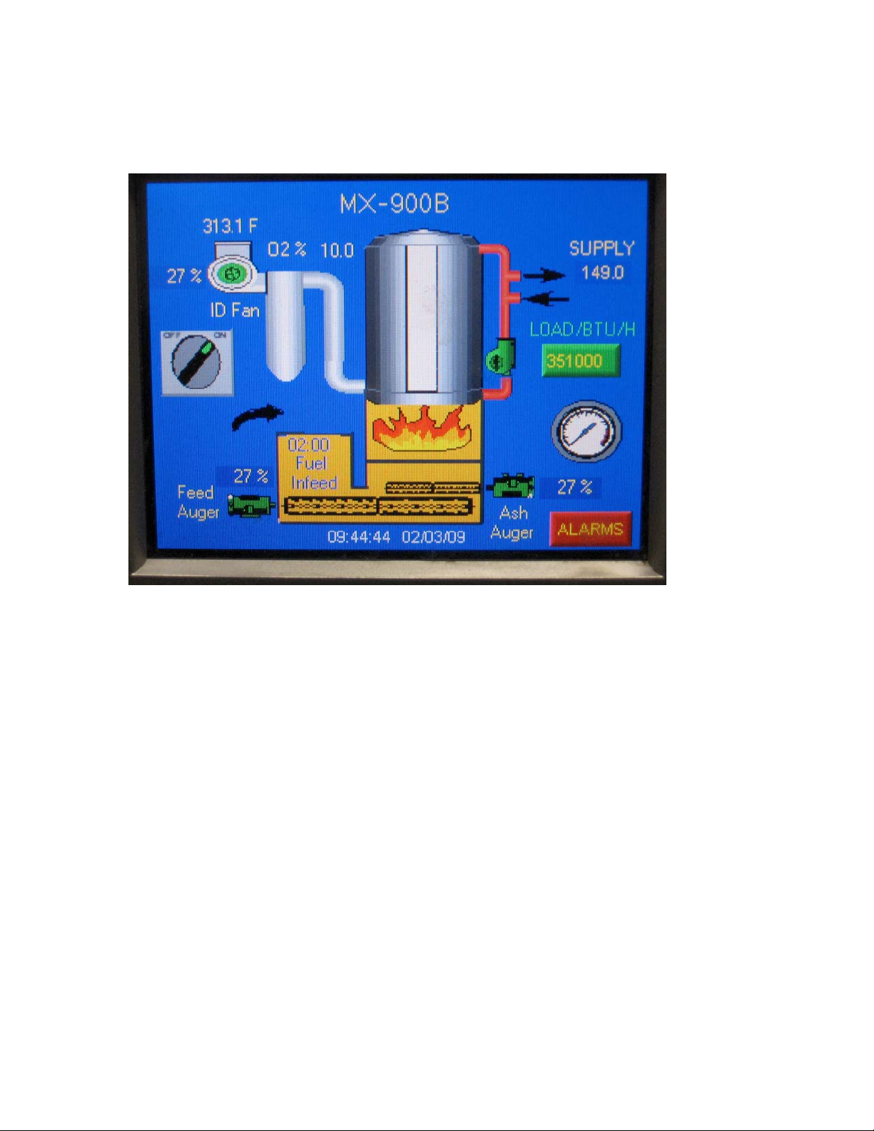
Overview Screen
On / Off Rotary Switch
• Press Switch icon to open Combustion System control screen.
• Displays Combustion System status: On (green), Off (red)
ID Fan
• Press ID Fan icon screen icon to open ID Fan control screen.
• Displays ID Fan motor run status: run (green), stop (red)
• % display, located to left of ID Fan icon, displays variable speed ID Fan
motor speed as a percentage of the full range bounded by the minimum
and maximum motor frequency set-points.
Flue Gas Temperature
• Located above the ID Fan icon
• Displays flue gas temperature, °F
O2 %
• Located to right of ID fan icon.
• Displays (%) oxygen concentration in flue gas
Max-Ox™ MX-900B Operators Manual, Rev. 0
Page 34 of 54
Page 35

Feed Auger Motor
Press Motor icon to open Feed Auger control screen
•
Displays Feed Auger motor status: run (green), stop (red)
•
% display, located above Feed Auger motor icon, displays variable
•
speed Feed Auger motor speed as a percentage of the available speed
range bounded by the minimum and maximum motor frequency setpoints.
Fuel In-Feed
• Press In-Feed icon to open Fuel InFeed control screen
• Displays time remaining until an automatic Metering Bin fill cycle
will occur.
Ash Auger Motor
• Press Motor icon to open Ash Auger control screen
• Displays Ash Auger motor status: run (green), stop (red)
• % display, located to right of Ash Auger motor icon, displays variable
speed Ash Auger motor speed as a percentage of the available speed
range bounded by the minimum and maximum motor frequency setpoints.
Alarms
• Press Alarm icon to open the Alarms control screen
Gage
• Press Gage icon to open the Gages screen
Boiler Pump
• Press Boiler Pump icon to open the Boiler Pump control screen.
• Displays Boiler Pump motor status: run (green), stop (red)
Load Btu/hr
• Displays the instantaneous power output of the boiler vessel, BTU/hr
Boiler Vessel
• Press Boiler Vessel icon to open Supply Temp. Controller screen.
Max-Ox™ MX-900B Operators Manual, Rev. 0
Page 35 of 54
Page 36
Flame
Flame image is displayed when the flue gas exhaust stack temperature
•
is at or above 200F, and also signifies that the Combustion Control
system has engaged the Automatic Control mode.
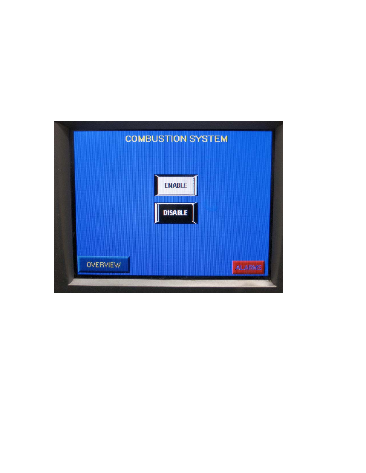
Combustion System Screen
Enable
• Press Enable icon to permit engagement of the automatic Combustion
Control when the flue gas exhaust stack temperature is at or above
200F.
Disable
• Press Disable icon to shut off the Fuel InFeed system and commence
automatic shutdown of the Combustion System.
Overview
• Press Overview icon to open the Overview screen
Max-Ox™ MX-900B Operators Manual, Rev. 0
Page 36 of 54
Page 37
Alarms
• Press Alarms icon to open the Alarms screen
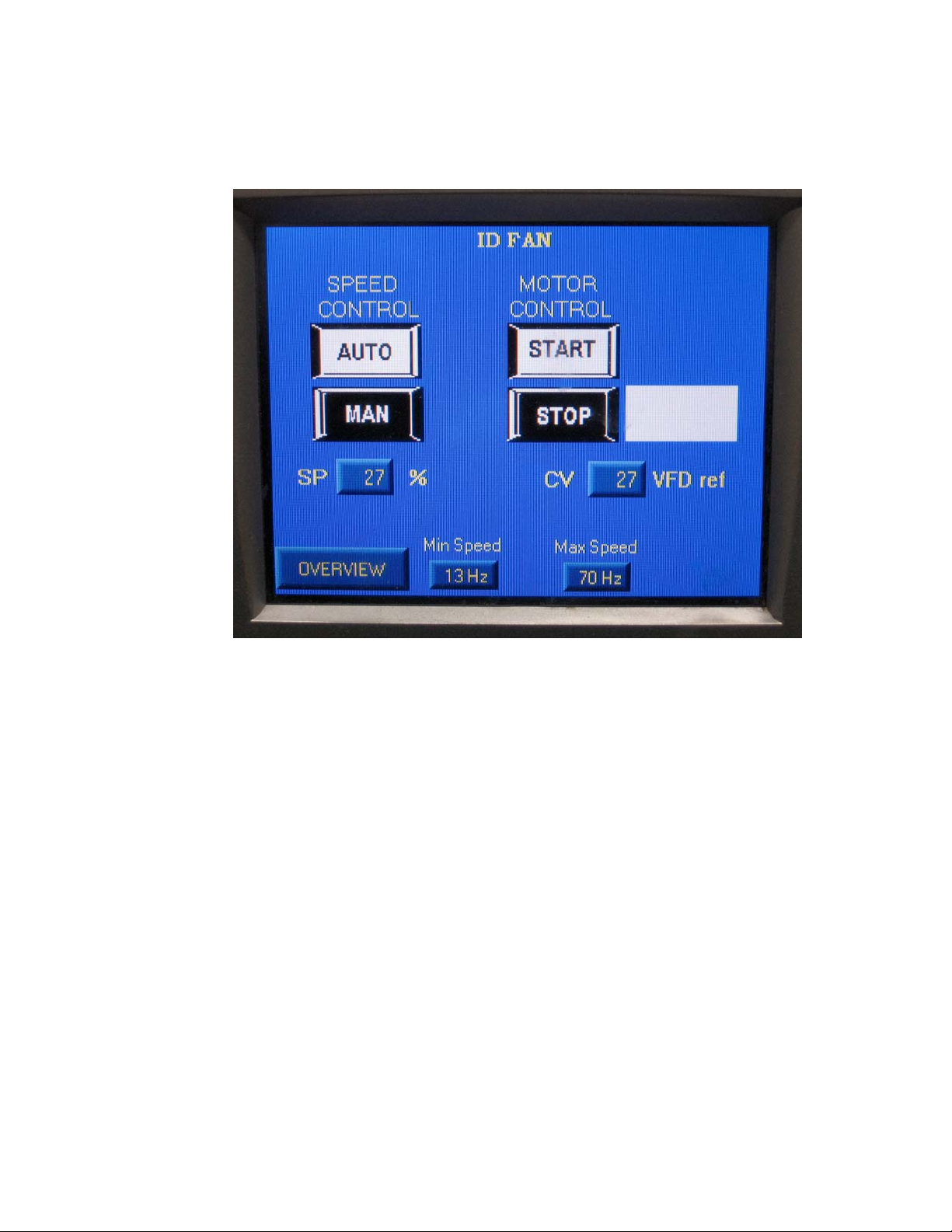
ID Fan Screen
Speed Control Auto
• Press Auto icon to enable ID Fan in automatic control when the flue
gas exhaust stack temperature is at or above 200F
Speed Control Manual
• Press Manual icon to engage ID Fan in manual control mode. Manual
mode is only available below 170F °F stack temperature (decreasing)
Speed Control SP (Set-Point)
• Press SP icon to change ID Fan speed set-point
• Displays the current ID Fan speed set-point as a percentage of the
available speed range bounded by the minimum and maximum motor
frequency set-points
Motor Control Start
• Press Start icon to manually start ID Fan
Max-Ox™ MX-900B Operators Manual, Rev. 0
Page 37 of 54
Page 38

Motor Control Stop
Press Stop icon to manually stop ID Fan
•
Motor Control CV
•
Displays ID Fan variable speed drive Control Value
Minimum Speed
•
Press Minimum icon to change the ID Fan minimum speed set-point
Maximum Speed
• Press Maximum icon to change ID Fan maximum speed set-point
Overview
• Press Overview icon to open the Overview screen
Max-Ox™ MX-900B Operators Manual, Rev. 0
Page 38 of 54
Page 39
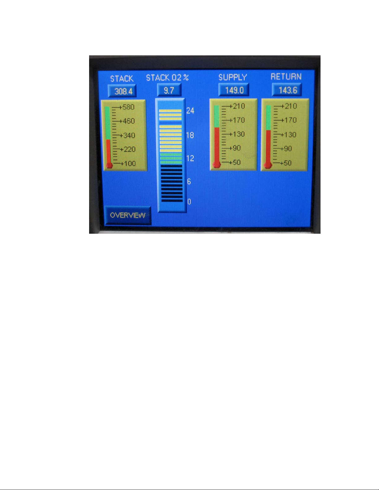
Gages Screen
Stack Temperature
• Displays flue gas exhaust stack temperature, °F
Stack O2 %
• Displays (%) oxygen concentration in flue gas
• Press Stack O2 bar scale icon to open the Stack O2 control screen.
Supply Temperature
• Displays boiler supply (outlet) water temperature, °F
• Press Supply Temperaature scale icon to open the Supply
Temperature Controller screen.
Return Temperature
• Displays the boiler return (inlet) water temperature, °F
Max-Ox™ MX-900B Operators Manual, Rev. 0
Page 39 of 54
Page 40
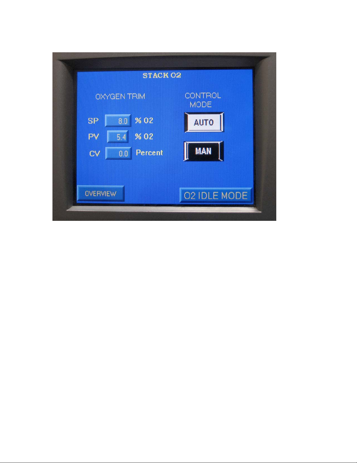
Stack O2 Screen
Oxygen Trim SP (Set-Point)
• Press SP icon to change the % Oxygen set-point.
Oxygen Trim PV
• Displays actual O2% concentration
Oxygen Trim CV
• Factory-use-only control system parameter.
Control Mode Auto
• Press Auto icon to engage automatic O2% control
Control Mode Manual
• Press manual icon to disengage automatic O2 % control
O2 Idle Mode
• Press O2 Idle Mode icon to display O2 Idle Mode screen
Overview
• Press Overview icon to return to Overview screen
Max-Ox™ MX-900B Operators Manual, Rev. 0
Page 40 of 54
Page 41
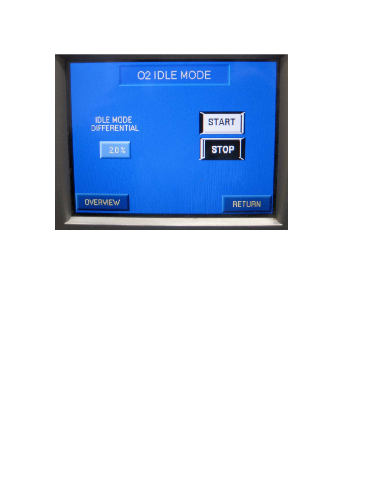
O2 Idle Mode Screen
Start
• Press Start icon to engage combustion system O2 idle mode
Stop
• Press Stop icon to disengage combustion system O2 idle mode
Idle Differential Mode
• Press Idle Differential mode icon to change the Idle Mode Differential
Return
• Press Return icon to return to Stack O2 screen
Overview
• Press Overview icon to return to Overview screen
Max-Ox™ MX-900B Operators Manual, Rev. 0
Page 41 of 54
Page 42
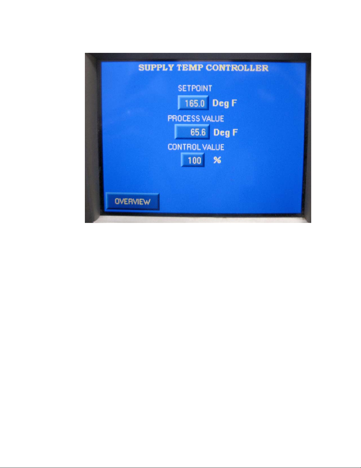
Supply Temperature Controller Screen
Set-point
• Displays boiler supply (outlet) water temperature control set-point, °F
• Press Set-point icon to change boiler supply water temperature
control set-point
Process Value
• Displays the actual boiler supply (outlet) water temperature, °F
Control Value
• Displays the instantaneous Combustion System power output as a
percentage of full power.
Overview
• Press Overview icon to open the Overview screen
Max-Ox™ MX-900B Operators Manual, Rev. 0
Page 42 of 54
Page 43
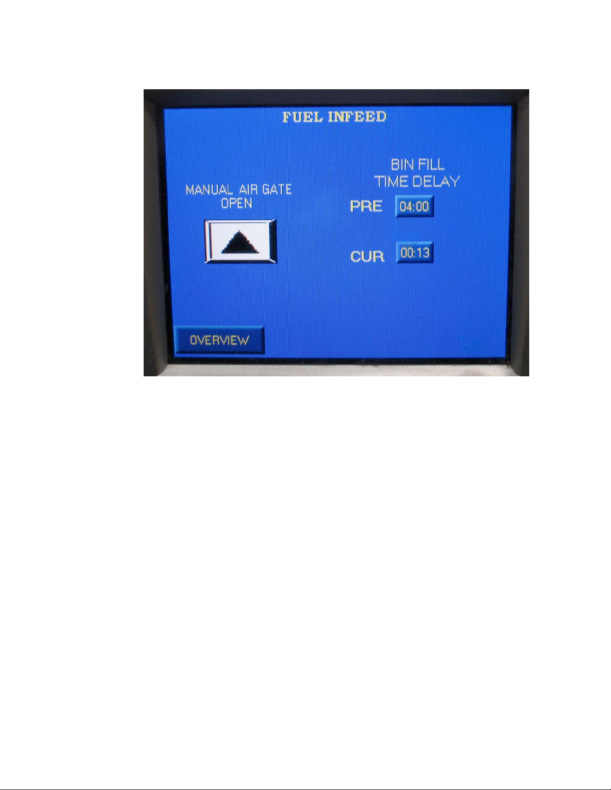
Fuel In-Feed Screen
Manual Air Gate Open
• Press Open icon to toggle open fuel Metering Bin Air Gate. Release
of the touch screen icon will close the Air Gate.
Bin Fill Time Delay Pre-set
• Displays the set-point time delay between Metering Bin refill cycles,
minutes
• Press PRE icon change Metering Bin Fill Time Delay set-point.
Bin Fill Time Delay Current Status
• Displays time remaining until Metering Bin refill cycle begins
Max-Ox™ MX-900B Operators Manual, Rev. 0
Page 43 of 54
Page 44
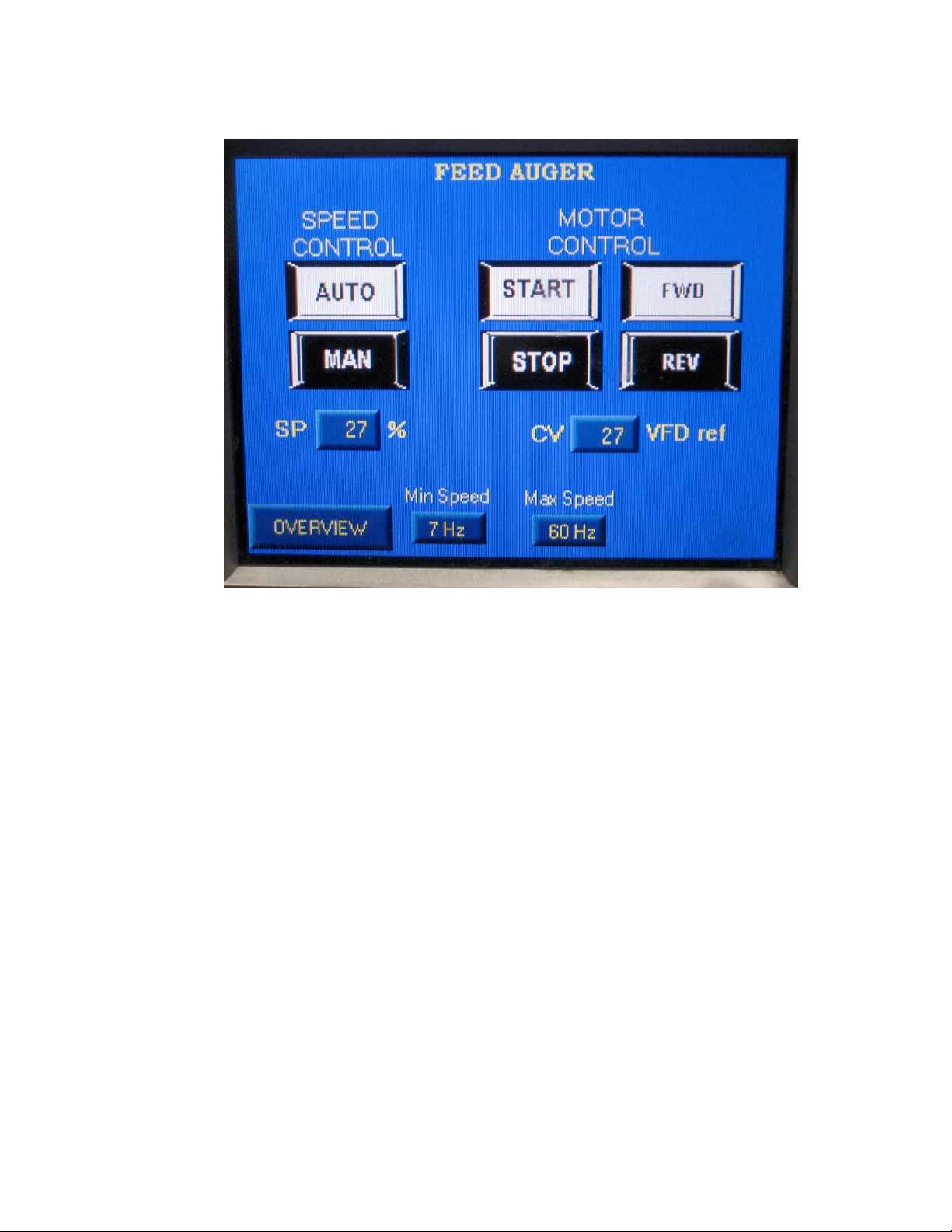
Feed Auger Screen
Speed Control Auto
• Press Auto icon to enable engage automatic speed control of Feed
Auger motor
Speed Control Manual
• Press Manual icon to disengage automatic speed control of Feed
Auger motor
Motor Control Start
• Press Start icon to start the Feed Auger motor
Motor Control Stop
• Press Stop icon to stop the Feed Auger motor
Motor Control Forward
• Press Forward icon to select continuous forward rotation of the Feed
Auger motor.
Max-Ox™ MX-900B Operators Manual, Rev. 0
Page 44 of 54
Page 45

Motor Control Reverse
Press Reverse icon to jog the Feed Auger motor in the reverse rotation
•
direction.
Speed Control SP (Set-point)
Displays Feed Auger motor speed set-point as a percentage of the
•
available speed range bounded by the minimum and maximum motor
frequency set-points.
Motor Control CV
• Displays Feed Auger Motor speed instantaneous control value as a
percentage of the available speed range bounded by the minimum and
maximum motor frequency set-points
Minimum Speed
• Press Minimum icon to change Feed Auger minimum speed set-point
Maximum Speed
• Press Maximum icon to change Feed Auger maximum speed set-point
Overview
• Press Overview icon to open the Overview screen
Max-Ox™ MX-900B Operators Manual, Rev. 0
Page 45 of 54
Page 46
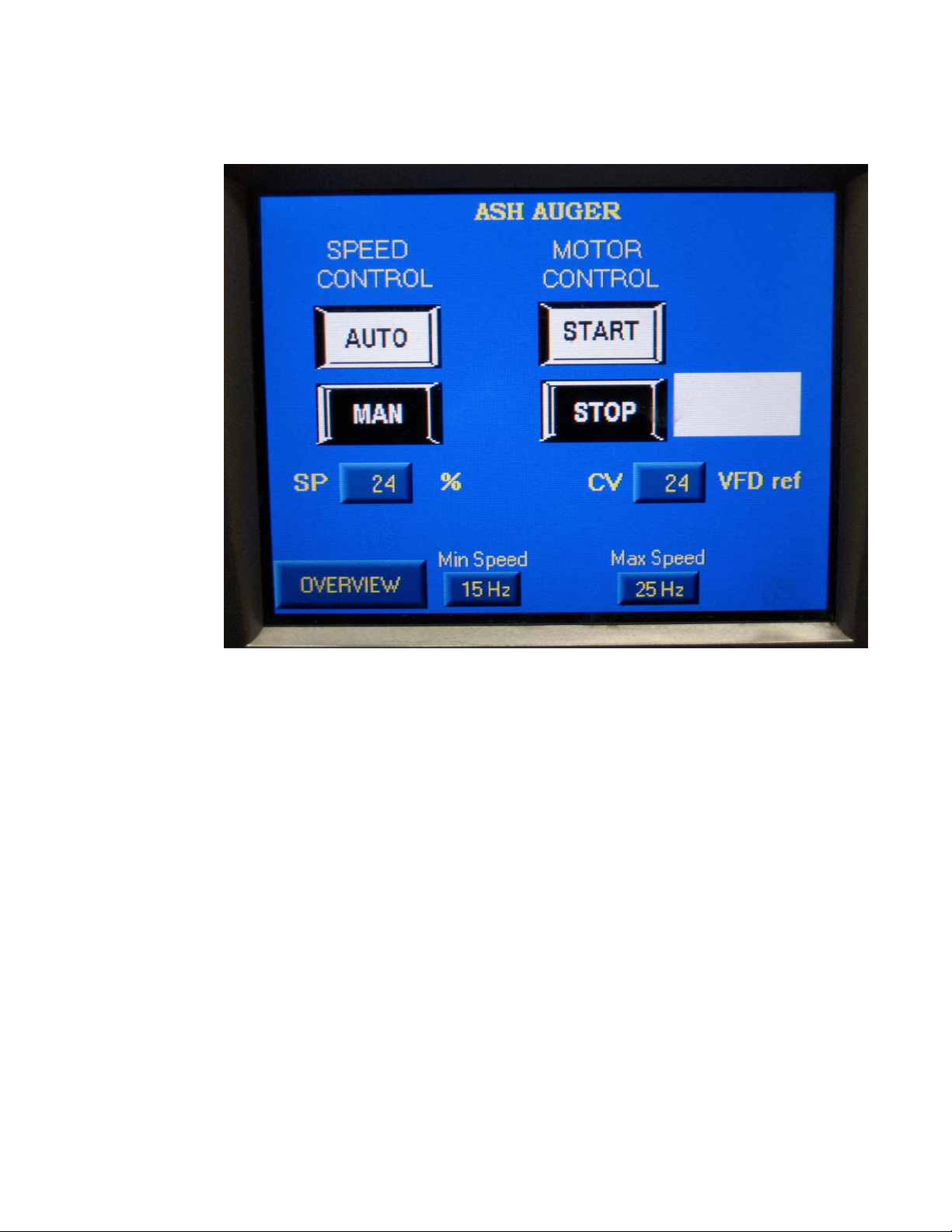
Ash Auger Screen
Speed Control Auto
• Press Auto icon to enable engage automatic speed control of Ash
Auger motor
Speed Control Manual
• Press Manual icon to disengage automatic speed control of Ash
Auger motor
Motor Control Start
• Press Start icon to start the Ash Auger motor
Motor Control Stop
• Press Stop icon to stop the Ash Auger motor
Max-Ox™ MX-900B Operators Manual, Rev. 0
Page 46 of 54
Page 47

Speed Control SP (Set-point)
Displays Ash Auger motor speed set-point as a percentage of the
•
available speed range bounded by the minimum and maximum motor
frequency set-points.
Motor Control
Displays Ash Auger Motor speed instantaneous control value as a
•
percentage of the available speed range bounded by the minimum and
maximum motor frequency set-points
Minimum Speed
• Press Minimum icon to change Ash Auger minimum speed set-point
Maximum Speed
• Press Maximum icon to change Ash Auger maximum speed set-point
Overview
• Press Overview icon to open the Overview screen
Max-Ox™ MX-900B Operators Manual, Rev. 0
Page 47 of 54
Page 48
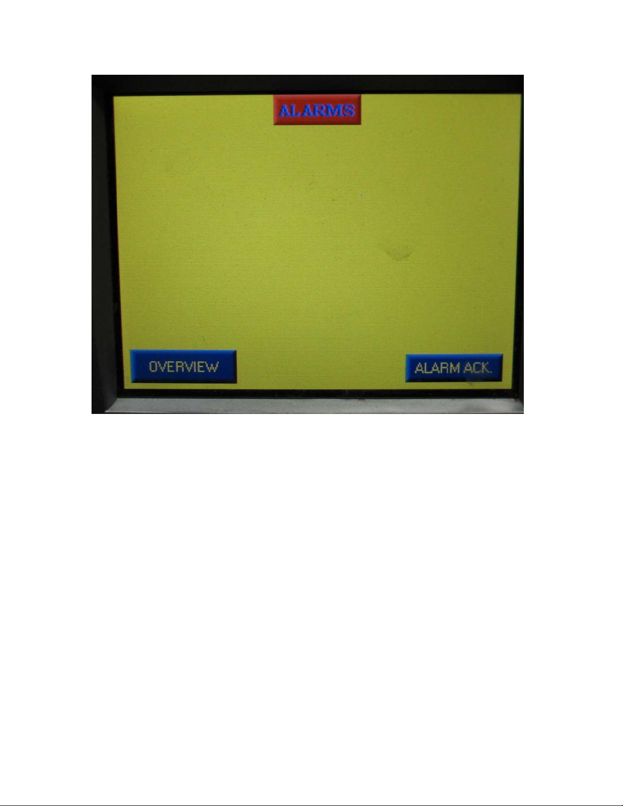
Alarm Screen
Alarms:
• Out of Fuel : Initiates on low stack temperature during automatic
combustion control
• ID Fan Air Flow: Initiates upon loss of
Proof of Draft Switch signal
• ID Fan VFD: Initiates upon ID Fan motor VFD Drive fault
• Ash Auger VFD: Initiates upon Ash Auger motor VFD Drive fault
• Feed Auger Rotation: Initiates upon Feed Auger jam
• Fuel Feed Auger VFD: Initiates upon Feed Auger motor VFD Drive
fault
• Metering Bin Air Gate Close: Initiates if gate position is opposite its
required position
• Metering Bin Air Gate Open: Initiates if gate position is opposite its
required position
• Emergency Stop: Initiates upon manual actuation of E-Stop button
• Boiler Pump Flow: Initiates upon loss of Flow Switch signal
Max-Ox™ MX-900B Operators Manual, Rev. 0
Page 48 of 54
Page 49
• Boiler High Limit: Initiates at boiler shell Aquastat 205°F set-point
• Boiler Low Water Cutoff: Initiates upon loss of boiler water level
• Stack High Limit: Initiates if stack temperature does not lower to
below 500 °F upon completion of an automatic power cut-back
maneuver initiated at a stack temperature of 520 °F.
• Burner Front Access Door Open: Initiates if gate position is
opposite its required position
• Burner Rear Access Door Open : Initiates if gate position is
opposite its required position
Alarm Acknowledge
• Press Alarm Ack. icon to acknowledge alarm
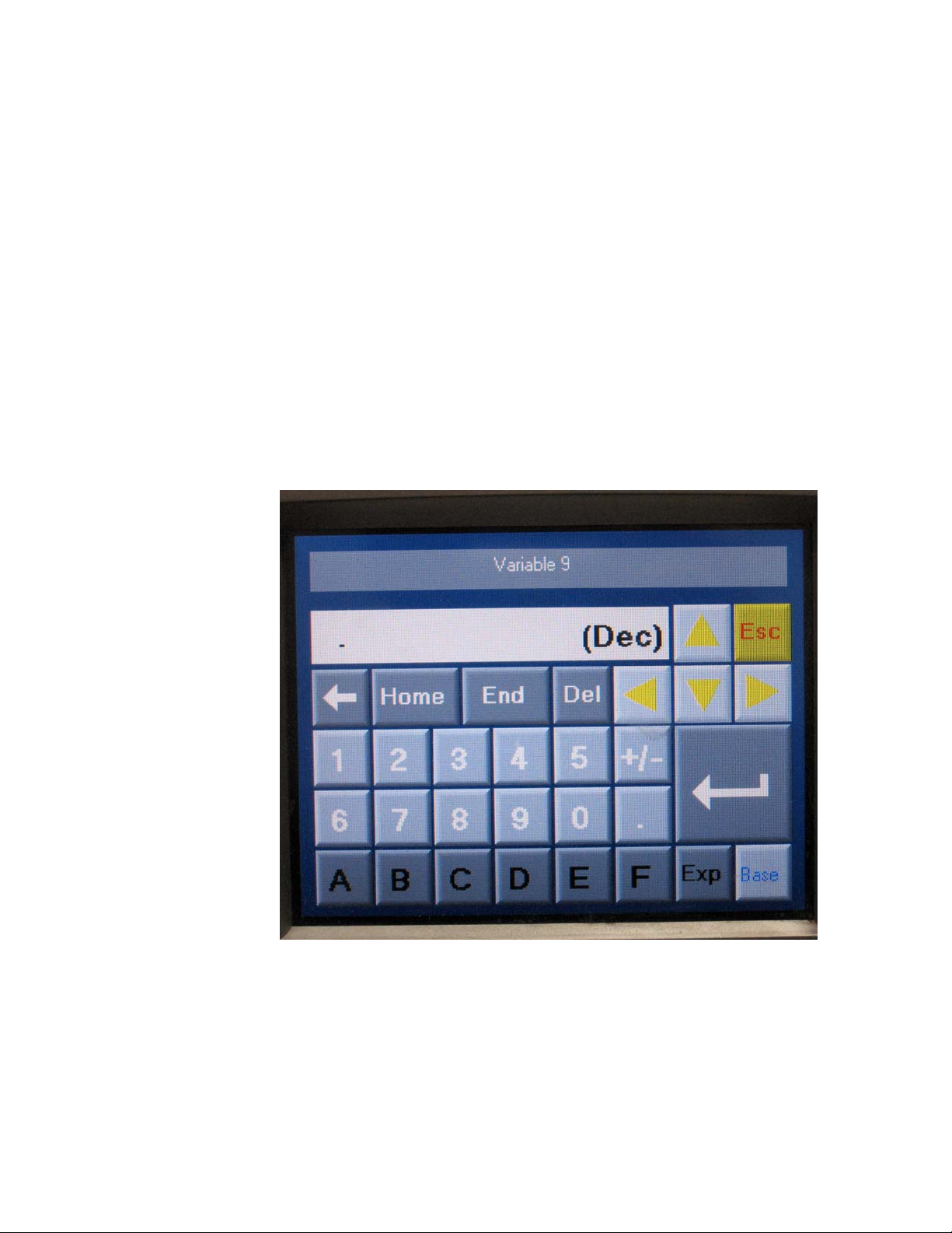
Keypad Entry Screen
Keypad Entry Screen
• Used as a touch keypad for operator entry of control system set-
points. Keypad functions are analogous to those found on a Personal
Computer keyboard.
Max-Ox™ MX-900B Operators Manual, Rev. 0
Page 49 of 54
Page 50

Ash Cleaning
The Ash bin must be cleaned whenever the ash level in the bin
reaches 75% of the bin height. Under continuous full power operation on
low ash content fuels, the ash bin will require emptying every two (2) to
three (3) days.
Note: Ash bin fill rates vary with fuel type ash content.
The MX-900B Unit should be cleaned of ash deposits every 2 to 3
weeks of operation. In general, the ash cleaning frequency is dependent on
the type of fuel being burned, and the rate of fuel consumption. The
experience you gain on your type of fuel, and its ash production
characteristics, will enable you to assess and establish your ash cleaning
schedule.
Fire Hazard. Ash and/or residue may ignite outside of the
combustion chamber. In the event of a fire:
• Press Emergency Stop Button
• Use Fire Extinguisher to contain fire
• Contact your local Fire Department
Fire Hazard. Collect ashes in a non-combustible container with a
tight-fitting lid. Do not place waste other than ashes in same
container.
Surfaces may be Hot! Please wear full coverage protective
clothing , shoes, leather gloves, and safety glasses when
performing routine maintenance on your MX-900B.
Max-Ox™ MX-900B Operators Manual, Rev. 0
Page 50 of 54
Page 51

To clean the ash from your MX-900B, proceed as follows:
1.
Shut down the Unit as per the Shut-down procedure in this manual.
2.
Ash cleaning may commence after all fire has extinguished in the
stoker, however glowing embers may still be present. Please adhere to
the Caution and Warning statements above.
3. Change the ID Fan minimum speed set-point to 58 Hertz, and start the
ID Fan in the Manual mode. The ID fan will now serve to evacuate
fugitive dust during the ash cleaning procedure.
4. Via the boiler access maintenance ladder and two boiler cat-walks
remove the four top panels from the top of the boiler.
5. Brush all ash deposits down into the outer perimeter boiler fire tubes.
6. Clean each fire-tube and fire-tube turbulator as follows: manually
raise and lower turbulator within its’ fire-tube while rotating the
turbulator. Access to the in-board fire-tubes will require removal of
the four in-board boiler first-pass gas deflectors.
Note: Do not mix turbulators. Turbulators are arranged so that the flue
gas flow through the second-pass boiler perimeter fire-tubes is
balanced equally. Three progressively larger bore flow restrictor
collars are attached to the turbulators nearest the ID fan.
7. Re-install and clamp all four boiler top panels.
8. One-at-a-time, open each boiler exhaust plenum clean-out door. Using
a metal ash rake, pull all ash from the exhaust plenum and into a
suitable metal container. Close and latch each clean-out door.
9. Open the front and rear stoker doors. Using a metal ash rake, pull all
ash from in and around the stoker and sweep into a suitable metal
container.
10. Un-bolt and remove the stoker access panel located on the front of
the unit (located behind the stoker front door.) Using an ash rake, pull
all ash from within the stoker head and place in a suitable metal
container. Reinstall the bolted access cover.
Max-Ox™ MX-900B Operators Manual, Rev. 0
Page 51 of 54
Page 52

11. Clean and lubricate the ash ring as follows: Wearing gloves,
manually lift the heavy steel ash ring upward from the stoker rear door
side, and push outward towards the stoker front door. The rig is
heavy, and therefore removal is best performed with two people.
Brush off all surfaces of the ash ring, and lubricate the inside bore of
the ash ring with dry film bonded molybdenum disulphide spray.
Reinstall the ash ring.
12. Clean the cyclone ash container as follows: Manually close the slide
gate above the cyclone as container. Un-latch the ash container, and
dispose of its ash contents properly. Reinstall the ash container and relatch. Open the manual slide gate and tighten its thumbs screw.
Note: open the manual slide gate prior to re-installing the ash
container in order for the ID Fan draft to assist in seating the ash
container against its gasketed lid.
13. Stop the ID Fan and re-set its minimum speed to 13 Hertz.
14. Clean the Ash Bin (ash auger bin) as follows: un-latch the ash bin
from the ash auger trough. Dispose of the contents properly. Re-install
and latch the Ash Bin.
15. Vacuum any fugitive ash dust from around the MX-900B.
Routine Lubrication
ID Fan Bearings: Every 3 months of operation, add high quality high
temperature grease to both ID Fan shaft pillow block bearings using a grease
gun.
Ash Auger Drive Train: Every 3 months of operation, add high quality high
temperature grease to both Ash Auger Drive Train grease zerk fittings
located on the stoker base adjacent to the ash auger drive motor gear box and
chain sprocket.
Max-Ox™ MX-900B Operators Manual, Rev. 0
Page 52 of 54
Page 53

Boiler Water Treatment Program:
Follow a bi-annual (every 6 months) commercial boiler water chemistry
program for boiler water chemical analysis, chemical treatment, boiler
water total-dissolved solids blow-down, and boiler make-up water
addition for an open-system (non-pressurized) hydronic heating boiler.
Failure to follow a commercial water treatment program for corrosion
control of your boiler will void the Limited Warranty on your boiler
vessel whetted components.
Feed Auger Jam Clearing Procedure
In the event a Feed Auger jam occurs that does not clear itself under the
automatic control of the PLC, the Feed Auger motor will stop and a
“Rotation Fault” alarm will occur. Proceed as follows:
1. On the Alarm screen, acknowledge the alarm.
2. On the Feed Auger screen, re-start the Feed Auger motor by pressing
the “Start” icon.
Note: the Feed Auger motor will jog momentarily in the reverse
direction, and then proceed to run in the forward direction.
3. If the “Rotation Fault” alarm does not recur, proceed with normal
operation of the MX-900B.
4. If the “Rotation Fault” recurs, the MX-900B must be shut down, and
the Feed Auger train cleaned as follows:
5. Perform a normal shut-down of the MX-900B.
6. Switch “Off” the electrical disconnect on the electrical controls panel.
7. Perform a “Lock-out / Tag-out” procedure on the MX-900B electrical
disconnect switch. to ensure no MX-900B motors can start.
Max-Ox™ MX-900B Operators Manual, Rev. 0
Page 53 of 54
Page 54

Note: The control panel electrical disconnect switch is equipped with
a hinged red plastic “Lock-out” lock tab. To deploy the lock tab, use a
small straight-blade screwdriver to gently pry open the hinged red
lock tab.
By hand, remove all fuel from the Metering Bin. Then visually inspect
8.
for the Feed Auger obstruction and dislodge / remove it, if the
obstruction is within reach.
Note: It is easier to clean out the Metering Bin of the Air Gate
assembly is removed from the Metering Bin.
9. If the obstruction is not within reach through the Metering Bin
opening, then the auger gear reducer / motor assembly, and helical
auger shaft must be removed from the Metering Bin in order to clear
the obstruction.
10. During re-assembly, take care to ensure that Feed Auger alignment is
proper such that the auger does not rub anywhere along its length. If
the auger rubs, reposition the gear reducer mounting plate vertically or
horizontally, within the travel limits of the over-sized bolt holes, to
create auger clearance. Torque mounting bolts properly.
Do not attempt to clear the jam by repeated operation of the Feed Auger in
the manual reverse jog mode because fuel in the Metering Bin will pack
tight into the back of the Metering Bin and result in bending of the helical
auger flight adjacent to the gear reducer.
Max-Ox™ MX-900B Operators Manual, Rev. 0
Page 54 of 54
 Loading...