

Page 1

SL55+ User Manual
Page 2

Page 3
SL55+
This product is marked with:
in accordance with the Class II product
requirements specified in the R+TTE Directive,
1999/5/EC.
"We hereby declare that the above named
product is in conformity to all the essential
requirements of Directive 1999/5/EC".
French
Translation
Nous déclarons que le produit référencé
ci-dessus satisfait aux exigences
R&TTE 1999/5/EC qui lui sont applicables.
S
panish Translation
Certificamos que el aparato es conforme con lo
establecido en las disposiciones de la
Directiva 1999/5/CE.
German
Translation
"Wir möchten hiermit bekanntgeben, daß das oben
genannte Produkt in Übereinstimmung mit allen
erforderlichen Bedürfnissen der 1999/5/EC Direktive
seht"
It
alian Translation
Con la presente dichiariamo che il prodotto suindicato
è conforme a tutti i requisiti essenziali della Direttiva
1999/5/CEE.
ENGLISH
1
0168 !
Page 4

CONTENTS
INTRODUCTION . . . . . . . . . . . . . . . . . . . . . . . . . . . . . .4
MAXON SL55+ . . . . . . . . . . . . . . . . . . . . . . . . . . . . . . .4
KEY FEATURES . . . . . . . . . . . . . . . . . . . . . . . . . . . . . .4
PLUG IN OPTIONS . . . . . . . . . . . . . . . . . . . . . . . . . . . .4
SIGNALLING OPTIONS . . . . . . . . . . . . . . . . . . . . . . . .4
ROBUSTNESS BUILT-IN . . . . . . . . . . . . . . . . . . . . . . . .4
DESCRIPTION OF RADIO . . . . . . . . . . . . . . . . . . . . . .5
NOTES TO THE USER . . . . . . . . . . . . . . . . . . . . . . . .6
SAFETY INFORMATION . . . . . . . . . . . . . . . . . . . . . . . .6
CARE OF THE EQUIPMENT . . . . . . . . . . . . . . . . . . . .6
PREPARING FOR USE . . . . . . . . . . . . . . . . . . . . . . . .7
UNPACKING AND INSPECTION . . . . . . . . . . . . . . . . . .7
FITTING INSTRUCTIONS . . . . . . . . . . . . . . . . . . . . . .7
ATTACHING AND REMOVING THE ANTENNA . . . . . . .7
ATTACHING AND REMOVING THE BATTERY PACK . .7
ATTACHING AND REMOVING THE BELT CLIP . . . . . .7
RADIO PERFORMANCE . . . . . . . . . . . . . . . . . . . . . . .8
BATTERY CHARGING AND CARE . . . . . . . . . . . . . .8
RECYCLING / DISPOSAL OF BATTERIES . . . . . . .9
SL55+ OPERATION . . . . . . . . . . . . . . . . . . . . . . . . . . .9
POWER ON / VOLUME / POWER OFF . . . . . . . . . . . .9
CHANNEL SELECT / CHANNEL SCAN . . . . . . . . . . . . .9
MONITOR / TONE DEFEAT . . . . . . . . . . . . . . . . . . . . .9
TRANSMIT . . . . . . . . . . . . . . . . . . . . . . . . . . . . . . . . . .9
RECEIVE . . . . . . . . . . . . . . . . . . . . . . . . . . . . . . . . . .10
STATUS INDICATORS AND
AUDIBLE ALERT TONES . . . . . . . . . . . . . . . . . . . . . .10
DIAGNOSTIC MESSAGES . . . . . . . . . . . . . . . . . . . .11
UNPROGRAMMED CHANNEL . . . . . . . . . . . . . . . . . .11
RECEIVE ONLY CHANNEL . . . . . . . . . . . . . . . . . . . . .11
SCAN MODES . . . . . . . . . . . . . . . . . . . . . . . . . . . . . . .12
NORMAL CHANNEL SCAN . . . . . . . . . . . . . . . . . . . . .12
PRIORITY CHANNEL SCAN . . . . . . . . . . . . . . . . . . . .12
ENGLISH
2
Page 5

OTHER SCANNING FEATURES . . . . . . . . . . . . . . .13
OPTIONS . . . . . . . . . . . . . . . . . . . . . . . . . . . . . . . . . . .14
SOP55-01 SELCALL / SCRAMBLER MODULE . . . . . .14
VOICE PRIVACY OPTION (VP10 ) . . . . . . . . . . . . . . .14
ACCESSORIES . . . . . . . . . . . . . . . . . . . . . . . . . . . . . .14
ENGLISH
3
Page 6

ENGLISH
4
INTRODUCTION
MAXON SL55+
KEY FEATURES
16 Channels: allows flexible operation and system
expansion
Tri-colour LED indicator shows you the status of
the radio.
Top panel controls: for belt-mounted use
Rugged and reliable construction
PLUG IN OPTIONS
VP10 Inversion Scrambler, switchable between
clear or secure transmission
SOP55-01 Fixed Selcall and Inversion Scrambler module:
provides additional signalling facilities with Inversion
Scrambler for added security
SIGNALLING OPTIONS (STANDARD)
Continuous Tone Coded Squelch Signalling
(CTCSS) and Digitally Coded Squelch (DCS):
CTCSS / DCS helps to screen you from calls
intended for other users or user groups. It is
also used in some systems to access widearea repeaters.
ROBUSTNESS BUILT-IN
The SL55+ is of a sturdy construction and is dust and water
resistant, to the level set down in IEC529 level IP54, and
also withstands the new rigorous tests of US MIL STD 810F.
This makes the SL55+ ideal for operation in a variety of
harsh environments.
Page 7
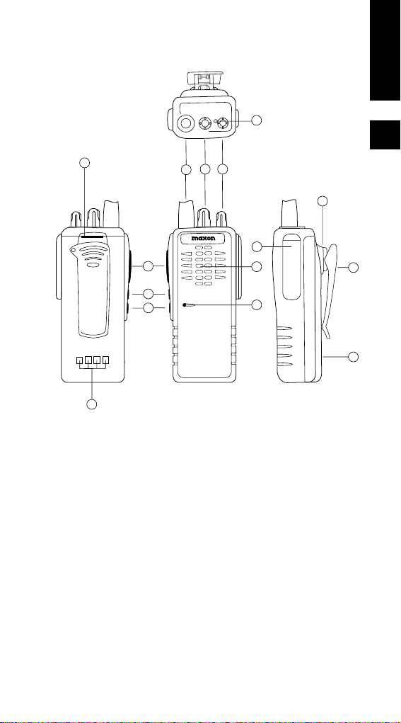
DESCRIPTION OF RADIO
1 Antenna
2 Channel Selector Knob
3 On / Off Volume control
4 Microphone
5 Push to talk (PTT) button
6 Monitor
7 Option button
8 Accessories / Programmer interface
9 Speaker
10 Battery catch
11 Busy / TX LED indicator
12 Belt-clip holder
13 Battery charge contacts
14 Battery
15 Belt-clip
ENGLISH
5
11
10
5
6
7
13
1
23
8
9
4
12
15
14
Page 8

NOTES TO THE USER
SAFETY INFORMATION
Do not hold the radio in such a manner that the antenna
is touching exposed parts of the body, especially the face
or eyes, while transmitting.
Do not transmit if antenna is damaged as minor burns
could occur if the metallic core is exposed and is touched.
Do not allow children to operate transmitter equipped
radio equipment.
Do not operate the radio near unshielded electrical
blasting caps or in an explosive atmosphere.
Do not press and hold the transmit switch (PTT) when not
actually wishing to transmit.
Never use the radio in an aircraft.
Never use the radio near to sensitive medical equipment
or in areas where instructed not to do so, e.g. Petrol filling
stations
When used in a vehicle, do not mount the radio unit on or
near the Airbag or Airbag activating device.
The use of an accessory not recommended or supplied by
Maxon may cause damage to equipment or injury to
personnel and may invalidate warranty.
When using any of the charging accessories, the mains
socket-outlet must be installed near the equipment. The
outlet must not be obstructed and must be easily
accessible at all times.
Never attempt to disassemble, modify or repair the unit
unless the work is carried out by a Maxon approved
Reseller. Incorrect assembly, modification or repair may
cause irreparable damage to your unit and will invalidate
warranty. For service or repair always return your radio to
an authorised Maxon Reseller.
CARE OF THE EQUIPMENT
Keep the exterior of the radio clean using a soft damp
cloth.
Do not submerge the radio.
Do not use solvents or spirits for cleaning as they may
damage the radio housing.
Do not carry the radio by the antenna.
Keep battery contacts clean and free of corrosion.
Do not store batteries in a discharged state.
ENGLISH
6
Page 9

PREPARING FOR USE
UNPACKING AND INSPECTION
Unpack the radio and check that you have received the
following items:
SL55+ handportable radio
Battery pack
Antenna
Belt clip
If any of these items are missing, please contact your dealer.
FITTING INSTRUCTIONS
ATTACHING AND REMOVING THE ANTENNA
A high quality matched antenna is supplied with the SL55+
radio. Install the antenna by turning clockwise into the
antenna receptacle on the top of the radio, until it is firmly
seated. Do not over tighten. To remove the antenna,
reverse the above procedure.
Never operate the radio without the antenna fitted.
Always use Maxon approved antenna.
ATTACHING AND REMOVING THE BATTERY PACK
Please refer to the picture on the inside rear cover.
Hold the radio face down in your hand. To attach the
battery pack, pick up the pack by the sides and hold it so
that the latch is facing upward. Place the bottom of the
battery pack into the base of the radio at approximately a 45º
angle. Gently push battery into the radio back until the
battery latch snaps firmly into place.
Remove the battery pack by holding the radio face down in
your hand. Press down and hold the battery latch. Gently
pull the battery out and away from the radio.
ATTACHING AND REMOVING THE BELT CLIP
The belt clip attaches to the radios battery pack. To attach
the belt clip, hold the clip and slide it into the recessed area
at the top of the pack. A click will verify the clip is securely
positioned. To remove the clip, press and hold the release
tab toward the clip while gently pulling the belt clip assembly
off the radio.
ENGLISH
7
Page 10

RADIO PERFORMANCE
Optimum positioning of the radio will significantly improve the
effective transmission range, i.e. hold the radio close,
approximately 5cm from your mouth whilst talking. Mounting
the radio on a belt and using a lapel microphone may
degrade performance in marginal signal areas. In poor
signal areas, moving the radio just a few metres may
produce a clearer signal.
BATTERY CHARGING AND CARE
To ensure peak performance from your radio, the battery
pack must be fully charged. To obtain maximum capacity and
performance it is recommended that you cycle your new
batteries with at least 3 charges and 2 discharges.
Remove the charger base and power supply from the
packaging, and plug in the power supplys DC connector into
the jack on the back of the charging base. Plug the AC
power cord into the standard mains AC outlet.
To charge a battery while attached to a radio, simply place the
radio into the front charging well. The charger will identify the
battery condition, and then automatically initiate a charge
mode rapid or top-up / trickle.
To charge a battery removed from the radio, place the
battery into the rear charging well. Again, the charger will
identify the battery condition, and automatically rapid charge
or top-up / trickle charge, the battery pack.
Note the colour of the LED charge indicators: red for rapid
charge cycle, green for the top-up / trickle charge cycle.
When using both charging wells, only one can rapid charge
at a time. The front charging well always has priority for rapid
charging. After the front well cycles from rapid to top-up /
trickle charge, the back well will initiate its rapid charge
mode. Again, note the colour of the charging wells LED to
define the current charging cycle.
Note: To ensure peak performance from your radio,
periodically discharge the battery completely and recharge
fully. This action will prevent the battery from developing a
memory of short-term use, and will permit a good service
life.
To prolong battery life in general usage, make sure that the
radio is programmed to use the power save mode.
ENGLISH
8
Page 11

RECYCLING / DISPOSAL OF BATTERIES
The battery should be recycled at the end of its useful life.
Under various local laws, Ni-MH and Ni-Cd batteries must be
recycled or disposed of properly and cannot be discarded in
landfills or incinerators.
For further information on how to safely dispose of your used
batteries, contact your dealer.
SL55+ OPERATION
POWER ON / VOLUME / POWER OFF
Turn the radio on by rotating the off/on/volume control
clockwise.
You will hear a click and (if enabled via dealer programming),
the radios self-test alert tones. Increase the radio volume by
continuing the clockwise rotation.
To turn the radio off, rotate the control anti-clockwise until a
click is heard.
CHANNEL SELECT / CHANNEL SCAN
To change radio channels, simply rotate the Channel Knob
until the desired channel is reached.
If your radio has been programmed for scanning, you must
rotate the knob to the channel that has been programmed to
begin scanning.
MONITOR / TONE DEFEAT
The monitor button is located on the side of the SL55+ below
the PTT button. Your radio may be set-up to either allow or
dis-allow monitoring of a channel. Press and hold the
monitor button to listen to the channel.
When on, the radio will continue to receive even if the signal
is very low. This may assist clarity if the audio chops on
and off while receiving.
TRANSMIT
Check the colour of the radios top-panel LED. It will
illuminate orange if RF activity is present; it will not be
illuminated if the radio indicates a clear channel. See page
11.
When the channel is clear, hold the radio microphone area
approximately 5cm from your mouth, keeping the antenna
ENGLISH
9
Page 12

vertical. Press and hold the PTT button on the side of the
radio, and begin speaking in a clear, normal tone. Release
the PTT button when you have finished speaking.
CAUTION: Operation of the transmitter without a proper
antenna fitted may result in permanent damage to the radio.
NOTE: The radios LED will illuminate red continuously when
you have the PTT button pressed and are transmitting. If the
red LED starts flashing, the battery needs to be recharged
and transmission will cease. Recharge the battery fully
before attempting further transmissions.
RECEIVE
When you have finished transmitting, release the PTT button
to receive.
STATUS INDICATORS AND AUDIBLE ALERT TONES
The SL55+ radio has a microprocessor control, which
provides a range of audible alert tones. Upon each powerup, a quick melody* indicates that the self-test of the
microprocessor functions has been completed. A sequence
of audible tones* may be sounded with any of the following
conditions:
Attempting to transmit on a channel set for
receive only
Attempting to transmit on a channel that is
already in use when busy channel lockout has
been programmed into the radio*
Transmitting time has exceeded time-out timer
programmed length*
Low battery condition
Selecting a channel with no programmed
frequency
* Indicates a function that is initially programmed into the radio
by your Maxon dealer.
Note: All audible tones can be programmed off for silent
operation.
ENGLISH
10
Page 13

DIAGNOSTIC MESSAGES
In addition to the low battery condition, a flashing red status
LED may also indicate fault conditions
Should your radio apparently not operate correctly, replace
the battery with one known to be fully charged. If the
condition persists, or the radio emits an unexpected
continuous pattern of audio beeps, or will not transmit or
receive as it does normally, return the radio to your Maxon
dealer.
UNPROGRAMMED CHANNEL
If your radio has been set-up for less than the maximum
number of channels, turning to a blank channel will cause
your radio to beep and the status LED will flash red,
indicating that the channel is unusable.
RECEIVE ONLY CHANNEL
Your radio may be set-up to receive on a channel but not to
transmit. If PTT or call functions are started on such a
channel, the radio will beep and the LED will flash red.
ENGLISH
11
STATUS DESCRIPTION LED COLOUR AUDIBLE ALERT
NORMAL Power On - Ready N/A Melody
Busy Amber N/A
Correct Call Green N/A
Transmit Red N/A
Busy Lockout Amber,Flashing Single Tone
IN SCAN Scan is initiated Green,Flashing N/A
WARNING Time-out Timer N/A Single Tone
Battery Low Red,Flashing Four Tone,Repeated
ERROR EEPROM Error Red,Flashing Single Tone,Repeated
PLL Error Red,Flashing Double Tone,Repeated
Filtering Error Red,Flashing Three Tone,Repeated
Page 14

SCAN MODES
Scanning is a Dealer programmable feature that allows you
to monitor a number of channels. Your Dealer will help you
define a channel scan list to be programmed into a scan
channel. Once that channel location is selected, scan is
initiated.
NORMAL CHANNEL SCAN
Once the scan list is programmed you can initiate scan.
Simply move the channel selector knob to the scan channel
position and the radio will start to scan. The top panel LED
can be programmed to flash green as the radio is scanning.
If RF activity, with any programmed options, is detected on
any of the channels in the scan list, the radio will stop on that
channel and monitor it. If programmed for normal scan TX,
you will be able to transmit on that active channel during the
programmed scan delay time. The scan delay time is the
amount of time the radio will stay on that channel once the
activity has ceased. The radio will resume scanning once
the scan delay time has expired. Scanning will continue until
the channel is changed.
PRIORITY CHANNEL SCAN
A single channel may be programmed as the Priority
channel. The radio will constantly monitor this channel while
scanning and when the radio has stopped on an active
channel. If a call is detected on the Priority channel, the
radio will automatically move to, and remain on, the Priority
channel for as long as the priority conversation takes place.
Priority channel activity takes precedence over all other
conversations.
NOTE: Priority channel scan and look back require that
the radio leave the active channel for a fraction of a second
(at regular intervals) to check the priority channel for
activity. Depending how the radio is programmed, this may
or may not be noticeable as breaks on the active channel
for that same fraction of a second.
ENGLISH
12
Page 15

OTHER SCANNING FEATURES
Look Back: Any channel, when not in the scan mode, can
be programmed to look back at the Priority channel.
This feature is ideal for those who do not need scan as
defined above, but want to make sure that they never miss
a call on the Priority channel, if another channel has
been selected. Once a look back channel has been
selected, the radio will periodically look back at the
Priority channel. If activity is detected on the Priority
channel, the radio will move to that channel for as long as
it remains active.
Scan Channel Delete: To temporarily delete a channel
from the scan list, simply press the monitor button while
stopped on the channel to be deleted, during the scanning
routine. This will remove that channel from the scan list
until the channel is changed or the radios power is reset.
When the power is restored or the scan list channel
position is selected, the original Dealer programmed scan
list will be activated.
CTCSS / DCS Scanning: The SL55+ can be programmed
by your Dealer to scan for tone. This will help block out
unwanted calls.
Normal Scan TX: Allows a transmission only after a call is
received, depending on the programmed scan delay time.
After the scan resumes, and a transmission is made, the
radio will sound an alarm (two beeps) and will not allow a
transmission.
Priority Scan TX: Allows a transmission after a call is
received depending on programming scan delay time.
The transmission will be made on the channel that the call
was received. After the scan resumes, if a transmission is
made, the radio will transmit on the programmed priority
channel.
Priority Only TX: Allows a transmission on the priority
channel when scanning and not stopped on an active
channel. It can also be programmed to always transmit on
the priority channel if scanning or stopped on an active
channel.
Receive Only Scan: This only allows reception. If a
transmission is attempted at any time, the radio will sound
an alarm (two beeps) and will not allow the transmission.
ENGLISH
13
Page 16

OPTIONS
A number of plug-in Option boards are available for the
SL55+, which enhance the features of the radio. Please
refer to your dealer for details of any options fitted to your
radio (Note: only one option can be fitted at any time).
SOP55-01 SELCALL / SCRAMBLER MODULE
If your radio has been upgraded with the SOP55-01, a range
of additional signalling options is available. These features
can reduce the time spent receiving messages meant for
other radios and makes better use of the radio channel. This
module also provides basic inversion scrambling to deter
casual eavesdroppers.
With the SOP55-01 fitted, the operation of the radio will
change. A User Manual with further details on the operation
of the radio with Selcall is included with the module.
VOICE PRIVACY OPTIONS (VP10)
The SL55+ can be fitted with a Voice Privacy option that
provide protection against unauthorised eavesdroppers.
(VP10) The Fixed Inversion Scrambler provides a solution
against the casual eavesdropper, with simple operation.
Mode Selection
To turn the Voice Privacy option on, the SL55+ Option button
is used. Press the Option button to toggle between Clear /
Secure mode. The Status LED is used to indicate the
current mode.
ACCESSORIES
A full range of Maxon accessories are available to use with
this product. Please contact your Maxon Reseller for more
information or visit www.maxon.co.uk
ENGLISH
14
Page 17

15
FRANÇAIS
SL55+
This product is marked with:
in accordance with the Class II product
requirements specified in the R+TTE Directive,
1999/5/EC.
Nous déclarons que le produit référencé
ci-dessus satisfait aux exigences
R&TTE 1999/5/EC qui lui sont applicables.
0168 !
Page 18

FRANÇAIS
16
SOMMAIRE
INTRODUCTION . . . . . . . . . . . . . . . . . . . . . . . . . . . . .18
MAXON SL55+ . . . . . . . . . . . . . . . . . . . . . . . . . . . . . .18
PRINCIPALES CARACTÉRISTIQUES . . . . . . . . . . . . .18
OPTIONS . . . . . . . . . . . . . . . . . . . . . . . . . . . . . . . . . .18
OPTIONS DE SIGNALISATION . . . . . . . . . . . . . . . . . .18
ROBUSTESSE INTÉGRÉE . . . . . . . . . . . . . . . . . . . . .18
DESCRIPTION DU RADIO . . . . . . . . . . . . . . . . . . . . .19
NOTES À L'ATTENTION DE L'UTILISATEUR . . . . . .20
SÉCURITÉ . . . . . . . . . . . . . . . . . . . . . . . . . . . . . . . . .20
ENTRETIEN DU MATÉRIEL . . . . . . . . . . . . . . . . . . . .20
PRÉPARATION AVANT UTILISATION . . . . . . . . . . .21
DÉBALLAGE ET INSPECTION . . . . . . . . . . . . . . . . . .21
INSTALLATION . . . . . . . . . . . . . . . . . . . . . . . . . . . . . .21
MISE EN PLACE ET RETRAIT DE L'ANTENNE . . . . .21
MISE EN PLACE ET RETRAIT DE LA BATTERIE . . . .21
MISE EN PLACE ET RETRAIT DE
LA PINCE DE CEINTURE . . . . . . . . . . . . . . . . . . . . . .24
PERFORMANCE DU RADIO . . . . . . . . . . . . . . . . . .22
RECHARGE ET ENTRETIEN DE LA BATTERIE . . . . . .23
RECYCLAGE / ÉLIMINATION DES BATTERIES . . . . . .23
FONCTIONNEMENT DU SL55+ . . . . . . . . . . . . . . . .23
MARCHE/VOLUME/ARRÊT . . . . . . . . . . . . . . . . . . . .23
SÉLECTION/BALAYAGE DES CANAUX . . . . . . . . . . .23
SURVEILLANCE / ÉCHEC DE TONALITÉ . . . . . . . . . .23
TRANSMISSION . . . . . . . . . . . . . . . . . . . . . . . . . . . . .24
RÉCEPTION . . . . . . . . . . . . . . . . . . . . . . . . . . . . . . . .24
INDICATEURS D'ETAT ET SONORITÉS D'ALARME . .24
MESSAGES DE DIAGNOSTIC . . . . . . . . . . . . . . . . .25
CANAL NON PROGRAMMÉ . . . . . . . . . . . . . . . . . . . .25
CANAL DE RÉCEPTION SEULEMENT . . . . . . . . . . . .25
MODES DE BALAYAGE . . . . . . . . . . . . . . . . . . . . . .26
BALAYAGE DE CANAUX NORMAL . . . . . . . . . . . . . . .26
BALAYAGE À CANAL PRIORITAIRE . . . . . . . . . . . . . .26
Page 19

17
FRANÇAIS
AUTRES DISPOSITIFS DE BALAYAGE . . . . . . . . .27
OPTIONS . . . . . . . . . . . . . . . . . . . . . . . . . . . . . . . . . . .28
MODULE SOP55-01 SELCALL / SCRAMBLER . . . . . .28
OPTION DE SÉCURITÉ VOCALE (VP10) . . . . . . . . . .28
ACCESSOIRES . . . . . . . . . . . . . . . . . . . . . . . . . . . . . .28
Page 20

FRANÇAIS
18
INTRODUCTION
MAXON SL55+
PRINCIPALES CARACTÉRISTIQUES
16 canaux : souplesse d'exploitation et d'expansion
du système
LED tricolore indique l'état du radio
Commandes sur le dessus : usage en ceinture
Construction robuste et fiable
OPTIONS
Scrambler à inversion VP10, alternable entre
transmission en clair ou sécurisée
Module Selcall fixe et scrambler à inversion
SOP55-01: fournit des dispositifs de
signalisation additionnels avec scrambler à
inversion pour un complément de sécurité
OPTIONS DE SIGNALISATION (STANDARD)
Continuous Tone Coded Squelch Signalling (CTCSS) et
Digitally Coded Squelch (DCS):
CTCSS / DCS fait écran entre vous et les appels destinés
à d'autres utilisateurs ou groupes d'utilisateurs. Il est
également utilisé dans certains systèmes pour accéder
aux répéteurs desservant des zones étendues.
ROBUSTESSE INTÉGRÉE
De construction robuste, le SL55+ est résistant à la
poussière et à l'eau et répond à la norme IEC529 niveau
IP54. Il supporte également les nouveaux tests rigoureux de
la norme US MIL STD 810F.
Tout cela rend le SL55+ idéal pour des environnements durs
divers.
Page 21

19
FRANÇAIS
DESCRIPTION DE LA RADIO.
1 Prise d'antenne
2 Bouton de sélection des canaux
3 Bouton M/A et réglage du volume
4 Microphone
5 Pédale d'émission
6 Indicateur Led TX /RX
7 Bouton d'écoute
8 Bouton option
9 Interface accessoires/programmation
10 Haut-parleur
11 Taquet batterie
12 Support clip de ceinture
13 Contacts de charge batterie
14 Batterie
15 Clip de ceinture
11
10
5
6
7
13
1
23
8
9
4
12
15
14
Page 22

FRANÇAIS
20
NOTES A L'ATTENTION DE
L'UTILISATEUR
SÉCURITÉ
Ne pas tenir le radio de telle sorte que l'antenne touche
des parties exposées du corps, plus particulièrement le
visage ou les yeux, durant la transmission.
Ne pas transmettre si l'antenne est endommagée car des
brûlures légères peuvent se produire si l'âme métallique
est exposée et touchée.
Ne pas laisser des enfants utiliser de matériel radio
équipé de transmetteur.
Ne pas utiliser le radio près d'amorces électriques non
protégées ou dans une atmosphère explosive.
Ne pas appuyer sur le bouton de transmission (PTT)
quand vous ne souhaitez pas transmettre.
Ne jamais utiliser le radio à bord d'un avion.
Ne jamais utiliser le radio près de matériel médical
sensible ou dans des zones où il est interdit de le faire,
par ex. stations service.
Quand vous utilisez le radio dans un véhicule, ne pas le
monter sur ou près de l'airbag ou du dispositif de
déclenchement de l'airbag.
L'utilisation d'un accessoire non recommandé ou fourni
par Maxon peut endommager le matériel ou entraîner des
préjudices corporels et pourrait invalider la garantie.
Quand vous utilisez l'un des accessoires de recharge, la
prise secteur doit être installée près du matériel. La prise
ne doit pas être obstruée et doit être facilement accessible
à tout moment.
Ne tentez jamais de démonter, modifier ou réparer
l'appareil sauf si le travail est exécuté par un revendeur
agréé par Maxon. Un montage, une modification ou une
réparation incorrects peuvent entraîner des dégâts
irréparables et invalider la garantie. Pour les révisions et
réparations, adressez-vous toujours à un revendeur agréé
par Maxon.
ENTRETIEN DU MATÉRIEL
L'extérieur du radio doit toujours être propre. Utilisez un
chiffon doux humide.
Ne submergez jamais le radio.
N'utilisez ni solvants ni alcools pour le nettoyage car
ils risquent d'endommager le boîtier du radio.
Ne portez pas le radio par l'antenne.
Les contacts de la batterie doivent rester propres et sans
corrosion.
Ne stockez pas les batteries à l'état déchargé.
Page 23

21
FRANÇAIS
PREPARATION AVANT UTILISATION
DÉBALLAGE ET INSPECTION
Déballez le radio et vérifiez que vous avez bien reçu les
éléments suivants :
Radio portatif SL55+
Batterie
Antenne
Pince de ceinture
Si l'un de ces éléments est manquant, contactez votre
revendeur.
INSTALLATION
MISE EN PLACE ET RETRAIT DE L'ANTENNE
Une antenne adaptée de haute qualité est fournie avec le
radio SL55+. Installez l'antenne en la faisant tourner dans le
sens des aiguilles d'une montre dans l'orifice destiné à
l'antenne sur le dessus de la radio, jusqu'à ce qu'elle soit
fermement en place. Ne serrez pas trop. Pour retirer
l'antenne, inversez la procédure ci-dessus.
N'utilisez jamais le radio sans l'antenne.
Utilisez toujours une antenne agréée Maxon.
MISE EN PLACE ET RETRAIT DE LA BATTERIE
Veuillez vous reporter au diagramme à l'intérieur du
couvercle arrière.
Tenez le radio à la main, face vers le bas. Pour fixer la
batterie, saisissez la batterie par les côtés et tenez-la de
telle sorte que le loquet soit face vers le haut. Placez le bas
de la batterie dans la base du
radio à un angle d'environ 45°. Enfoncez doucement la
batterie dans l'arrière du radio jusqu'à ce que le loquet de la
batterie se mette fermement en place avec un bruit sec.
Retirez la batterie en tenant le radio face vers le bas.
Enfoncez et retenez le loquet de la batterie. Retirez
doucement la batterie du radio.
MISE EN PLACE ET RETRAIT
DE LA PINCE DE CEINTURE
La pince de ceinture s'attache à la batterie du radio. Pour
attacher la pince de ceinture, prenez la pince en main et
faites-la glisser dans la partie creuse située sur le dessus de
la batterie. Un "clic" confirmera la mise en place de la pince.
Pour retirer la pince, enfoncez et retenez la languette vers
la pince tout en éloignant doucement la pince de ceinture du
radio.
Page 24

FRANÇAIS
22
PERFORMANCE DU RADIO
Un positionnement optimal du radio améliorera
considérablement la plage de transmission utile : tenez le
radio près (environ 5 cm) de votre bouche quand vous
parlez. Le montage du radio sur une ceinture et l'utilisation
d'un micro-cravate dégradent la performance dans les zones
de signal marginal. Dans les zones de signal faible, le
déplacement du radio de quelques mètres seulement peut
produire un signal plus clair.
RECHARGE ET ENTRETIEN
DE LA BATTERIE
Pour assurer une performance optimale de votre radio, la
batterie doit être entièrement chargée. Pour obtenir une
capacité et une performance maximales, il est recommandé
de soumettre vos batteries neuves à un cycle d'au moins 3
recharges et 2 décharges.
Retirez le chargeur et l'alimentation de l'emballage et
branchez le connecteur CC de l'alimentation dans la prise
jack au dos du chargeur. Branchez le cordon d'alimentation
CA dans la prise secteur CA.
Pour recharger une batterie attachée à un radio, placez
simplement le radio dans le support avant du chargeur. Le
chargeur identifiera l'état de la batterie et déclenchera
automatiquement un mode de recharge : rapide ou lent.
Pour recharger une batterie retirée du radio, placez la
batterie dans le support arrière du chargeur. A nouveau, le
chargeur identifiera l'état de la batterie et déclenchera
automatiquement la recharge rapide ou lente de la batterie.
Notez la couleur des indicateurs LED de recharge : rouge
pour cycle de recharge rapide, vert pour cycle de recharge
lent.
Quand vous utilisez les deux supports de chargeur, une
recharge rapide ne peut être assurée que par un seul à la
fois. Le support de chargeur avant a toujours la priorité pour
la recharge rapide. Quand le support avant passe de la
recharge rapide à la recharge lente, le support arrière passe
au mode de recharge rapide. Notez à nouveau la couleur de
l'indicateur LED du support de chargeur pour définir le cycle
de recharge courant.
Note: pour assurer une performance optimale de votre radio,
procédez régulièrement à une décharge et recharge
complètes de votre batterie. Cette action empêchera la
Page 25

23
FRANÇAIS
batterie de développer une "mémoire" d'usage à court terme
et permettra une bonne longévité de service.
Pour prolonger la durée de vie de la batterie en usage
général, assurez-vous que le radio soit programmé pour
utiliser le mode d'économie d'énergie.
RECYCLAGE / ELIMINATION
DES BATTERIES
La batterie devrait être recyclée à la fin de sa vie utile. Selon
diverses lois locales, les batteries Ni-MH et Ni-Cd doivent
être recyclées ou éliminées correctement et ne peuvent pas
être jetées dans des sites d'enfouissement ou des
incinérateurs.
Pour tout renseignement sur l'élimination de vos batteries
usées, contactez votre revendeur
FONCTIONNEMENT DU SL55+
MARCHE / VOLUME / ARRET
Mettez le radio en marche en faisant tourner le bouton
off/on/volume dans le sens des aiguilles d'une montre.
Vous entendrez un clic et (si cette option est activée par
programmation du revendeur) les tonalités d'alerte de test
automatique du radio. Augmentez le volume en continuant
de tourner dans le sens des aiguilles d'une montre.
Pour arrêter le radio, tournez le bouton dans le sens inverse
des aiguilles d'une montrer jusqu'à ce que vous entendiez un
clic.
SÉLECTION / BALAYAGE DES CANAUX
Pour changer de canal radio, tournez tout simplement le
bouton Channel jusqu'à obtention du canal voulu.
Si votre radio a été programmé pour le balayage, vous
devez faire tourner le bouton jusqu'au canal programmé pour
commencer le balayage.
SURVEILLANCE / ÉCHEC DE TONALITÉ
Le bouton "monitor" est situé sur le côté du SL55+, sous le
bouton PTT. Votre radio peut être réglé de manière à
permettre ou interdire la surveillance d'un canal. Enfoncez le
bouton Monitor pour écouter le canal.
Page 26

FRANÇAIS
24
Quand il est en marche, le radio continue de recevoir même
si le signal est très faible. La clarté peut être améliorée si
l'audio est interrompu et repris pendant la réception.
TRANSMISSION
Vérifiez la couleur de l'indicateur LED situé sur le dessus du
radio. Il sera allumé et orange en présence d'une activité RF.
Il ne sera pas allumé si le radio indique un canal "clair". Voir
page 25.
Quand le canal est "clair", tenez la partie micro du radio à
environ 5 à 8 cm de votre bouche, en maintenant l'antenne à
la verticale. Enfoncez le bouton PTT situé sur le côté du
radio et commencez à parler sur un ton clair et normal.
Relâchez le bouton PTT quand vous avez fini de parler.
ATTENTION: l'utilisation du transmetteur sans une antenne
correcte peut entraîner l'endommagement permanent du
radio.
NOTE: L'indicateur LED du radio reste allumé en rouge
quand le bouton PTT est enfoncé et que vous transmettez.
Si l'indicateur rouge commence à clignoter, la batterie a
besoin d'être rechargée et la transmission sera interrompue.
Rechargez la batterie entièrement avant de tenter toute
autre transmission.
RÉCEPTION
Quand vous avez terminé de transmettre, relâchez le bouton
PTT pour recevoir.
INDICATEURS D'ETAT ET
SONORITÉS D'ALARME
Le SL55+ possède une commande à microprocesseur
fournissant diverses sonorités d'alarme. A chaque mise en
marche, une mélodie* rapide indique que le test automatique
des fonctions du microprocesseur a été exécuté. Une suite
de tonalités* peut être entendue dans les cas suivants :
Vous tentez de transmettre sur un canal dédié
exclusivement à la réception.
Vous tentez de transmettre sur un canal déjà utilisé
quand un verrouillage de canal occupé a été programmé
dans le radio*
Le temps de transmission a dépassé le temps limite
programmé dans la temporisation*
La batterie est faible
Vous avez sélectionné un canal sans fréquence programmée
Page 27

25
FRANÇAIS
* Indique une fonction qui est initialement programmée à
l'état désactivé pour un fonctionnement silencieux.
Note: Toutes les tonalités peuvent être programmées
désactivées pour un fonctionnement silencieux.
MESSAGES DE DIAGNOSTIC
En plus de la faiblesse de la batterie, un indicateur LED
rouge clignotant peut indiquer une défaillance.
Si votre radio semble ne pas fonctionner correctement,
remplacez la batterie par une batterie que vous savez être
entièrement chargée. Si le problème persiste ou si le radio
émet une série inattendue de "bips", ne transmet pas ou
encore ne réceptionne pas normalement, retournez-le à
votre revendeur Maxon.
CANAL NON PROGRAMMÉ
Si votre radio a été réglé pour moins que le nombre
maximum de canaux et si vous vous branchez sur un canal
vierge, votre radio émettra un "bip" et l'indicateur d'état
clignotera en rouge pour indiquer que le canal n'est pas
utilisable.
CANAL DE RÉCEPTION SEULEMENT
Votre radio peut être réglé pour réceptionner sur un canal
mais ne pas transmettre. Si des fonctions PTT ou d'appel
sont entamées sur un tel canal, le radio émettra un "bip" et
l'indicateur LED clignotera en rouge.
ETAT DESCRIPTION COULEUR DE SONORITÉ
L'INDICATEUR D'ALARME
LED
NORMAL En marche - Prêt S/O Mélodie
Occupé Orange S/O
Appel correct Vert S/O
Transmission Rouge S/O
Verrouillage occupé Orange,clignotant Tonalité simple
BALYAGE Le balayage
EN COURS a été entamé Vert, clignotant S/O
ALERTE Temporisation S/O Une seule tonalité
Batterie faible Rouge,clignotant Quatre tonalités,
répétées
ERREUR Erreur d'EEPROM Rouge,clignotant Une seule tonalité,
répétée
Erreur de PLL Rouge,clignotant Tonalité double,
répétée
Erreur de filtrage Rouge,clignotant Trois tonalités,
répétées
Page 28

FRANÇAIS
26
MODES DE BALAYAGE
Le balayage est une caractéristique programmable par le
revendeur et qui vous permet de surveiller plusieurs canaux.
Votre revendeur vous aidera à définir une "liste de balayage"
de canaux à programmer dans un canal de balayage. Une
fois le canal sélectionné, le balayage est entamé.
BALAYAGE DE CANAUX NORMAL
Une fois que la liste de balayage est programmée, vous
pouvez entamer le balayage. Il vous suffit de régler le bouton
de sélection de canal à la position du canal de balayage
pour que le radio commence le balayage. L'indicateur LED
du dessus peut être programmé de manière à clignoter en
vert pendant le balayage.
Si une activité RF, avec toutes les options programmées, est
détectée sur l'un ou plusieurs des canaux de la liste de
balayage, le radio s'arrête sur ce canal et le surveille. Si un
balayage normal TX est programmé, vous pouvez
transmettre sur ce canal actif pendant le retard de balayage
programmé. Le retard de balayage programmé correspond
au temps pendant lequel le radio reste sur ce canal une fois
que l'activité a cessé. Le radio reprend le balayage quand le
retard de balayage expire. Le balayage
continue jusqu'à ce qu'il y ait changement de canal.
BALAYAGE À CANAL PRIORITAIRE
Un canal unique peut être programmé en tant que canal
"prioritaire". Le radio assure la surveillance constante de ce
canal pendant le balayage et quand le radio s'arrête sur un
canal actif. Si un appel est détecté sur le canal "prioritaire",
le radio passe immédiatement à ce dernier et y reste jusqu'à
ce que la conversation prioritaire ait lieu. L'activité du canal
"prioritaire" a priorité sur toutes les autres conversations.
NOTE: Le balayage à canal "prioritaire" et le "retour" exigent
que le radio laisse le canal actif pendant une fraction de
seconde (à des intervalles réguliers) pour vérifier l'activité du
canal "prioritaire". Selon la programmation du radio, ceci
peut ou non se remarquer sous forme de "coupures" sur le
canal actif pendant cette même fraction de seconde.
Page 29

27
FRANÇAIS
AUTRES DISPOSITIFS DE BALAYAGE
Retour : Tous les canaux, quand ils ne sont pas en mode
de balayage, peuvent être programmés pour se
"retourner" vers le canal "prioritaire". Ce dispositif est idéal
pour ceux qui n'ont pas besoin du type de balayage décrit
plus haut mais souhaitent être sûrs de ne jamais manquer
un appel sur le canal "prioritaire" si un autre canal a été
sélectionné. Une fois qu'un canal de "retour" est
sélectionné, le radio "se retourne" périodiquement vers le
canal "prioritaire". Si une activité est détectée sur le canal
"prioritaire", le radio passe à ce canal et y reste tant qu'il
est actif.
Supprimer canal de balayage : Pour supprimer
provisoirement un canal de la liste de balayage, appuyez
tout simplement sur le bouton "monitor" au moment de
l'arrêt sur le canal à supprimer durant la routine de
balayage. Ceci retire ce canal de la liste de balayage
jusqu'à ce que le canal soit changé ou que le radio soit
remis en marche. Quand le radio est remis en marche ou
qu'il est réglé à la position de la liste de balayage, la liste
de balayage originale programmée par le revendeur est
activée.
Balayage CTCSS / DCS : Le SL55+ peut être programmé
par votre revendeur pour rechercher une tonalité. Ceci
aide à bloquer les appels indésirables.
TX balayage normal : Permet une transmission
seulement après réception d'un appel, en fonction du
retard de balayage programmé. Quand le balayage
reprend et qu'une transmission a lieu, le radio émet une
sonorité d'alarme (deux bips) et ne permet pas de
transmission.
TX balayage prioritaire : Permet une transmission après
réception d'un appel en fonction du retard de balayage
programmé. La transmission a lieu sur le même canal que
le canal de réception de l'appel. Quand le balayage
reprend, si une transmission a lieu, le radio transmet sur
le canal "prioritaire" programmé.
TX prioritaire seulement : Permet une transmission sur
le canal "prioritaire" pendant le balayage sans arrêt sur le
canal actif. Il peut également être programmé pour
toujours transmettre sur le canal "prioritaire" pendant le
balayage ou un arrêt sur un canal actif.
Page 30

FRANÇAIS
28
Balayage réception uniquement : Ne permet que la
réception. Si une transmission est tentée à tout moment,
le radio émet une sonorité d'alarme (deux bips) et ne
permet pas la transmission.
OPTIONS
Plusieurs cartes d'options plug-in sont disponibles pour le
SL55+ pour rehausser les caractéristiques du radio. Veuillez
consulter votre revendeur pour tout renseignement sur les
options installées sur votre radio (Note: il n'est possible
d'installer qu'une seule option à la fois).
MODULE SOP55-01 SELCALL / SCRAMBLER
Si votre radio est doté d'un module SOP55-01, plusieurs
options de signalisation complémentaires sont disponibles.
Ces dispositifs permettent de réduire le temps passé à
réceptionner des messages destinés à d'autres radios et de
mieux utiliser le canal radio. Ce module assure également
un brouillage à inversion de base pour décourager les
oreilles indiscrètes.
Avec le module SOP55-01, le fonctionnement du radio est
modifié. Un manuel d'utilisation contenant des détails
supplémentaires sur le fonctionnement du radio avec Selcall
est inclus avec le module.
OPTION DE SÉCURITÉ VOCALE (VP10)
(VP10) Le scrambler à fréquence d'inversion fixe fournit une
solution contre les oreilles indiscrètes occasionnelles, à un
niveau de base.
Sélection de mode
Pour activer le mode de sécurité vocale, le bouton Option du
SL55+ est utilisé. Appuyez sur le bouton Option pour alterner
entre le mode Clair et Sécurité. L'indicateur LED d'état est
utilisé pour indiquer le mode courant.
ACCESSOIRES
Une gamme complète des accessoires de Maxon sont
disponible pour employer avec ce produit. Veuillez contacter
votre revendeur de Maxon pour plus d'information ou visitez
www.maxon.co.uk
Page 31

SL55+
This product is marked with:
in accordance with the Class II product
requirements specified in the R+TTE Directive,
1999/5/EC.
Certificamos que el aparato es conforme con lo
establecido en las disposiciones de la
Directiva 1999/5/CE.
29
ESPAÑOL
0168 !
Page 32

TABLE DES MATIERS
INTRODUCCIÓN . . . . . . . . . . . . . . . . . . . . . . . . . . . . .32
MAXON SL55+ . . . . . . . . . . . . . . . . . . . . . . . . . . . . . .32
CARACTERÍSTICAS PRINCIPALES . . . . . . . . . . . . . .32
OPCIONES ENCHUFABLES . . . . . . . . . . . . . . . . . . . .32
OPCIONES DE SEÑALES (ESTÁNDAR) . . . . . . . . . . .32
ROBUSTEZ INTEGRAL . . . . . . . . . . . . . . . . . . . . . . .32
DESCRIPCIÓN DE LA RADIO . . . . . . . . . . . . . . . . . . .33
NOTAS PARA EL USUARIO . . . . . . . . . . . . . . . . . . .34
INFORMACIÓN SOBRE SEGURIDAD . . . . . . . . . . . . .34
CUIDADO DEL EQUIPO . . . . . . . . . . . . . . . . . . . . . . .35
PREPARACIÓN PARA EL USO . . . . . . . . . . . . . . . .35
DESEMPAQUETADO E INSPECCIÓN . . . . . . . . . . . .35
INSTRUCCIONES PARA EL MONTAJE . . . . . . . . .35
MONTAJE Y DESMONTAJE DE LA ANTENA . . . . . . .35
MONTAJE Y DESMONTAJE
DEL PAQUETE DE BATERÍAS . . . . . . . . . . . . . . . . . .36
MONTAJE Y DESMONTAJE DEL
SUJETADOR EN CORREA . . . . . . . . . . . . . . . . . . . . .36
RENDIMIENTO DE LA RADIO . . . . . . . . . . . . . . . . .36
CARGA Y CUIDADO DE LA BATERÍA . . . . . . . . . .37
RECICLAJE / DESECHO DE LAS BATERÍAS . . . .38
FUNCIONAMIENTO DE LA RADIO SL55+ . . . . . . .38
CONEXIÓN / VOLUMEN / DESCONEXIÓN . . . . . . . . .38
SELECCIÓN DE CANALES / ESCANEO DE CANALES38
MONITOR / ANULACIÓN DE TONOS . . . . . . . . . . . . .38
TRANSMISIÓN . . . . . . . . . . . . . . . . . . . . . . . . . . . . . .39
RECEPCIÓN . . . . . . . . . . . . . . . . . . . . . . . . . . . . . . . .39
INDICADORES DEL ESTADO ACTUAL Y TONOS
AUDIBLES DE ALERTA . . . . . . . . . . . . . . . . . . . . . . . .39
MENSAJES DE DIAGNÓSTICO . . . . . . . . . . . . . . . .40
CANAL SIN PROGRAMAR . . . . . . . . . . . . . . . . . . . . .41
CANAL PARA RECEPCIÓN SOLAMENTE . . . . . . . . .41
ESPAÑOL
30
Page 33

MODALIDADES DE ESCANEO . . . . . . . . . . . . . . . .41
ESCANEO DE CANALES NORMALES . . . . . . . . . . . .41
ESCANEO DE CANAL PRIORITARIO . . . . . . . . . . . . .42
OTRAS PRESTACIONES DE ESCANEO . . . . . . . .42
OPCIONES . . . . . . . . . . . . . . . . . . . . . . . . . . . . . . . . . .53
MÓDULO "SOP55-01 SELCALL / SCRAMBLER" . . . .53
OPCIONES DE PRIVACIDAD DE VOZ (VP10) . . . . . .54
ACCESSORIOS . . . . . . . . . . . . . . . . . . . . . . . . . . . . .54
31
ESPAÑOL
Page 34

INTRODUCCIÓN
MAXON SL55+
CARACTERÍSTICAS PRINCIPALES
16 canales: permite un funcionamiento flexible y la
expansión del sistema
Indicador LED de tres colores que muestra el estado
actual de la radio
Controles del panel superior: para uso montado en correa
Construcción robusta y fiable
OPCIONES ENCHUFABLES
"VP10 Inversion Scrambler", que permite conmutar
entre transmisión libre o segura
Módulo "SOP55-01 Fixed Selcall" y "Inversion Scrambler":
proporciona más facilidades de señales, con el dispositivo
"Inversion Scrambler" para mayor seguridad
OPCIONES DE SEÑALES (ESTÁNDAR)
"Continuous Tone Coded Squelch Signalling" (CTCSS:
Señalización codificada de circuito silenciador de tono
continuo) y "Digitally Coded Squelch" (DCS: Circuito
ilenciador codificado digitalmente):
El dispositivo CTCSS / DCS contribuye a excluir llamadas
dirigidas a otras personas o grupos de usuarios. También
sirve en algunos sistemas para obtener acceso a
repetidores de área amplia.
ROBUSTEZ INTEGRAL
El SL55+ es de una construcción robusta, y es resistente al
polvo y al agua hasta el nivel establecido en IEC529 Nivel
IP54. Además, es capaz de satisfacer los nuevos y rigurosos
tests de US MIL STD 810F. Todo ello hace que el SL55+ sea
ideal para su uso en una amplia variedad de entornos duros.
ESPAÑOL
32
Page 35

DESCRIPCIÓN DE LA RADIO
1 antena
2 botones de selección de canales
3 conexión / desconexión y control de volumen
4 micrófono
5 pulsar este botón para hablar
6 botón monitor
7 botón de opciones
8 Interfaz de los accesorios / del programador
9 altavoz
10 pestillo de la batería
11 indicador alimentado: En uso / TX
12 montura de sujetador en correa
13 contactos de carga de batería
14 batería
15 sujetador en correa
33
ESPAÑOL
11
10
5
6
7
13
1
23
12
8
9
4
15
14
Page 36

NOTAS PARA EL USUARIO
INFORMACIÓN SOBRE SEGURIDAD
No se debe sostener la radio de tal forma que la antena
esté en contacto con partes descubiertas del cuerpo
humano, en especial la cara y los ojos, mientras se está
trasmitiendo.
No se debe transmitir si la antena está dañada. Se
podrían producir quemaduras menores si el centro
metálico queda al descubierto y se toca.
No se debe dejar que los niños operen con equipamiento
de radio equipada con transmisor.
No se debe operar la radio cerca de detonadores
eléctricos sin protección o en un entorno de explosivos.
No se debe pulsar y mantener pulsado el mando de
transmisión (PTT) cuando no se desea transmitir.
No se debe nunca usar la radio en el interior de un avión.
No se debe nunca usar la radio cerca de equipamientos
médicos sensitivos o en zonas donde haya instrucciones
de no usarla, como por ejemplo en gasolineras
Cuando se utiliza en el interior de un vehículo, no se debe
montar la unidad de radio encima o cerca del Airbag o el
dispositivo de activación del Airbag.
El uso de un accesorio no recomendado o suministrado
por la casa Maxon podría causar daños al equipamiento o
lesiones al personal, y puede ser causa de invalidez de la
garantía.
Cuando se utiliza cualquiera de los accesorios para
cargar, el enchufe eléctrico de salida de la red debe
encontrarse cerca del equipo. El enchufe de salida no
debe quedar obstruido, y debe ser fácilmente accesible en
todo momento.
No se debe nunca tratar de desmontar, modificar o
reparar el aparato, excepto cuando este trabajo lo realiza
un Concesionario aprobado por Maxon. Una montura,
modificación o reparación incorrecta puede causar un
daño irreparable a la unidad, y puede ser causa de
invalidez de la garantía. Si se necesita un servicio o
reparación, se debe enviar siempre la radio a un
Concesionario autorizado por Maxon.
ESPAÑOL
34
Page 37

CUIDADO DEL EQUIPO
Se debe mantener limpia la parte exterior de la radio
valiéndose de un paño suave humedecido.
La radio no debe ser sumergida en ningún líquido.
No se deben usar solventes ni líquidos con alcohol para
limpiarla, puesto que podrían dañar la montura de la
radio.
No se debe coger la radio por la antena.
Se deben mantener limpios y libres de corrosión los
contactos de la batería.
No se deben conservar las baterías en estado de escarga.
PREPARACIÓN PARA EL USO
DESEMPAQUETADO E INSPECCIÓN
Se desempaqueta la radio y se comprueba que se ha
recibido todo lo siguiente:
Radio portátil a mano modelo SL55+
Paquete de baterías
Antena
Sujetador en correa
Si falta algo, póngase en contacto con el vendedor.
INSTRUCCIONES PARA EL MONTAJE
MONTAJE Y DESMONTAJE DE LA ANTENA
La radio SL55+ viene provista de una antena adaptada de
calidad superior. Se instala la antena haciendo que gire en
dirección a las agujas del reloj hasta entrar en el receptáculo
que hay en la parte de arriba de la radio, haciendo que
ajuste bien. No se debe apretar demasiado. Para quitar la
antena, se efectúa el procedimiento contrario.
No se debe nunca operar la radio sin que tenga puesta
la antena.
Se debe usar siempre una antena aprobada por Maxon.
35
ESPAÑOL
Page 38

MONTAJE Y DESMONTAJE
DEL PAQUETE DE BATERÍAS
Se ruega hacer referencia al dibujo que aparece en la
contraportada interior.
Se sostiene la radio boca abajo, en la mano. Para montar el
paquete de baterías, se coge el paquete por los lados y se
sostiene de forma que el pestillo esté mirando hacia arriba.
Se coloca la parte de abajo del paquete de baterías en la
base de la radio, aproximadamente a un ángulo de 45º. Se
empuja suavemente la batería para que penetre en la parte
de atrás de la radio, hasta que el pestillo de la batería
encaje firmemente en su sitio.
Para quitar el paquete de baterías se sostiene la radio
boca abajo, en la mano. Se hace presión hacia abajo en el
pestillo de la batería, sujetándolo. Se extrae la batería
tirando suavemente de ella hasta que sale de la radio.
MONTAJE Y DESMONTAJE
DEL SUJETADOR EN CORREA
El sujetador de correa se adosa al paquete de batería de la
radio. Para adosar el sujetador de correa, se sostiene el
sujetador y se hace deslizar hasta que entre en la parte
rebajada que hay en lo alto del paquete. Cuando hace clic,
esto prueba que ha quedado bien ajustado. Para quitar el
sujetador, se pulsa y se mantiene pulsada la orejeta de
desenganche presionando en dirección al sujetador,
mientras que a la vez se tira suavemente de la montura del
sujetador en correa hasta separarlo de la radio.
RENDIMIENTO DE LA RADIO
Si la radio está en la posición óptima se optimizará también
de modo significativo el alcance de la transmisión efectiva.
Se debe sostener la radio cerca de la boca, a unos 5 cm
aproximadamente, mientras se habla. Si se monta la radio
en el cinturón o se usa un micrófono de solapa, en las zonas
de señales marginales se puede degradar la transmisión. En
las áreas de señales de poca calidad, con trasladar la radio
unos metros más allá puede que se consiga obtener una
señal más clara.
ESPAÑOL
36
Page 39

CARGA Y CUIDADO DE LA BATERÍA
Para obtener el mejor rendimiento de la radio, el paquete de
baterías debe estar cargado al máximo. Para conseguir su
máxima capacidad y rendimiento, se recomienda ciclar las
baterías nuevas por lo menos con 3 cargas y 2 descargas.
Se saca del envase la base del cargador y la toma de
corriente, y se enchufa el conector DC de la toma de
corriente en el enchufe hembra que hay en la parte de atrás
de la base del cargador. Se enchufa el cable tomacorrientes
AC en la salida de la red principal estándar AC.
Para cargar la batería mientras está adosada a la radio,
simplemente se coloca la radio en la posición de cargar que
hay en la parte de delante. El cargador identificará el estado
de la batería, y a continuación entrará automáticamente en
una modalidad de carga, que podrá ser: carga rápida, o bien
modalidad de recarga / carga lenta.
Para cargar una batería cuando está apartada de la radio,
se coloca la batería en la posición de cargar que hay en la
parte de atrás. Igual que antes, el cargador identificará el
estado en que se encuentra la batería, y cargará el paquete
de baterías poniéndose de modo automático en modalidad
de carga rápida, o bien de recarga / carga lenta.
Se debe observar el color de los indicadores LED de carga:
el rojo indica ciclo de carga rápida, el verde ciclo de recarga
/ carga lenta.
Cuando se utilizan ambas posiciones de carga, sólo se
puede hacer en una de ellas la carga rápida. La posición
delantera de carga tiene siempre prioridad para la carga
rápida. Después de que cambia el ciclo en la parte
delantera, pasando de carga rápida a recarga / carga lenta,
se iniciará en la posición de atrás la modalidad de carga
rápida. De nuevo, debe observarse el color LED en la
posición de carga, puesto que este color indica el ciclo de
carga vigente..
Nota: Para obtener el máximo rendimiento de la radio, de
debe dejar a intervalos regulares que la batería se
descargue del todo, volviendo a ser cargada hasta el
máximo, con lo cual se impedirá que la batería desarrolle
una "memoria" de uso a corto plazo y se contribuirá a que
sea posible una larga vida útil.
Para prolongar la vida de la batería en su uso general, el
usuario debe asegurarse de que la radio está programada
para utilizar la modalidad de ahorro de electricidad.
37
ESPAÑOL
Page 40

RECICLAJE / DESECHO DE LAS
BATERÍAS
La batería debe ser reciclada al final de su vida útil. De
acuerdo con las diversas leyes locales, las baterías de NiMH y Ni-Cd tienen que ser recicladas o desechadas de la
forma prescrita, y no pueden ser descartadas en vertederos
públicos o incineradores.
Para obtener más información sobre la forma de desechar
las baterías usadas de una manera segura, se ruega
dirigirse al vendedor o concesionario.
FUNCIONAMIENTO DE LA RADIO SL55+
CONEXIÓN / VOLUMEN / DESCONEXIÓN
Se conecta la radio haciendo girar en dirección de las agujas
del reloj el control de volumen y desconexión / conexión (off
/ on).
Se percibirá un clic y (si han sido activados por vía de
programación por el concesionario) se oirán los tonos de
alerta del auto-test de la radio. Para aumentar el volumen de
la radio, se continúa la rotación del control en la misma
dirección.
Para desconectar la radio, se hace girar el control en
dirección contraria a las agujas del reloj hasta que se oye
que hace clic.
SELECCIÓN DE CANALES /
ESCANEO DE CANALES
Para cambiar de canal en la radio, simplemente se hace
girar el Botón de Canales hasta que se llega al canal que se
busca.
Si la radio ha sido programada para escanear, se debe
hacer girar este botón hasta llegar al canal que ha sido
programado para iniciar el escaneo.
MONITOR / ANULACIÓN DE TONOS
El botón monitor se encuentra en la parte lateral de la radio
SL55+, debajo del botón PTT. La radio puede ser
configurada para permitir o no permitir el monitoreo de un
canal. Se debe pulsar y mantener pulsado el botón monitor
para escuchar el canal.
ESPAÑOL
38
Page 41

Cuando está puesta, la radio continuará recibiendo la señal
incluso si ésta es muy baja, lo cual puede contribuir a
conseguir una mayor claridad de transmisión si el sonido
"viene y se va" intermitentemente durante la recepción.
TRANSMISIÓN
Se debe comprobar el color LED del panel de arriba de la
radio. La luz será de color naranja si hay presente una
actividad RF; no habrá luz si la radio indica un canal
"expedito" (libre). Véase la página 40.
Cuando el canal está "expedito", se debe sostener la radio
de forma que la parte del micrófono esté a unos 5 cm de la
boca del usuario, mientras se mantiene la antena en
posición vertical. Se pulsa y se mantiene pulsado el botón
PTT que hay en la parte lateral de la radio, y se comienza a
hablar en tono claro y normal. Se suelta el botón PTT
cuando uno ha terminado de hablar.
PRECAUCIÓN: Si se hace funcionar el transmisor sin que
tenga puesta la antena correcta, se podrán causar daños
permanentes a la radio.
NOTA: La iluminación LED de la radio mostrará una luz roja
continua mientras se mantiene pulsado el botón PTT y se
está transmitiendo. Si la luz roja LED empieza a
"parpadear", es porque es necesario recargar la batería
hasta el máximo antes de intentar realizar otras
transmisiones.
RECEPCIÓN
Cuando se ha terminado la transmisión, se suelta el botón
PTT a fin de comenzar la recepción.
INDICADORES DEL ESTADO
ACTUAL Y TONOS AUDIBLES DE ALERTA
La radio SL55+ tiene un control microprocesador que
proporciona una gama de tonos audibles de alerta. Al
comenzar cada conexión se oye una melodía rápida* que
indica que ha sido completado el auto-test de las funciones
del microprocesador. Se podrá percibir una secuencia de
tonos audibles* si se da alguna de las siguientes
condiciones:
Si se intenta transmitir por un canal configurado para
recibir solamente
Si se intenta transmitir por un canal que ya se encuentra
en uso cuando ha sido programada en la radio la
39
ESPAÑOL
Page 42

exclusión de canal en uso*
Si el tiempo de transmisión excede la duración máxima
programada en el cronomedidor de duración máxima*
Si la batería está baja
Si se selecciona un canal sin frecuencia programada
* Indica una función que ha sido programada inicialmente en
la radio por el concesionario de Maxon.
Nota: Todos los tonos audibles pueden ser programados
para ser desconectados, si se desea que funcione en
silencio
MENSAJES DE DIAGNÓSTICO
Además de indicar que la batería está baja, el "parpadeo" de
la luz de estado LED sirve también para indicar que se
detecta algún mal funcionamiento
Si parece que la radio no funciona bien, lo primero que se
debe hacer es sustituir la batería por una que se sabe que
está cargada al máximo. Si todavía la radio no funciona
bien, o si emite un inesperado sonido continuo de "beeps"
(impulsos de audiofrecuencia, o "pitidos"), o si no transmite
o recibe de la manera normal, se debe llevar la radio al
concesionario Maxon.
ESPAÑOL
40
ESTADO DESCRIPCIÓN COLOR LED ALERTA AUDIBLE
Conectada a la red
NORMAL eléctrica - Lista N/A Melodía
para funcionar
En uso Ámbar N/A
Llamada correcta Verde N/A
Transmisión Rojo N/A
Exclusión "En uso" Parpadeo en ámbar Tono único
EN
ESCANEO Escaneo iniciado Parpadeo en verde N/A
AVISO Cronomedidor de N/A Tono único
duración máxima
Batería baja Parpadeo en rojo Cuatro tonos,
repetidos
ERROR Error EEPROM Parpadeo en rojo Tono único,repetido
Error PLL Parpadeo en rojo Tono doble,repetido
Error de filtro Parpadeo en rojo Tres tonos,repetidos
Page 43

CANAL SIN PROGRAMAR
Si la radio ha sido configurada para un número de canales
inferior al máximo, al tratar de sintonizar un canal vacío la
radio emitirá "beeps" ("pitidos") y la luz LED indicadora de
estado actual se mostrará en rojo y parpadeando, lo que
indica que ese canal no es utilizable.
CANAL PARA RECEPCIÓN SOLAMENTE
Es posible configurar la radio para que reciba pero no
transmita por un canal. Si se ponen en marcha las funciones
PTT o de llamada en este canal, la radio emitirá un sonido
"beep" y la luz LED se mostrará en rojo y parpadeará.
MODALIDADES DE ESCANEO
El escaneo (exploración) es una prestación programable por
el Concesionario que permite al usuario monitorear una
serie de canales. El Concesionario ayudará a definir una
"lista de escaneo" de canales a programar en un canal de
escaneo. Una vez seleccionada la localización de ese canal,
se inicia el escaneo.
ESCANEO DE CANALES NORMALES
Una vez que ha sido programada la lista de escaneo, se
puede proceder a escanear. Simplemente se pone el botón
selector de canales en la posición correspondiente a
escanear canales, y la radio iniciará el escaneo. El panel
LED superior puede ser programado para que parpadee con
luz verde mientras la radio está escaneando.
Si, con alguna de las opciones programadas, se detecta una
actividad RF en alguno de los canales de la lista de
escaneo, la radio se detendrá en ese canal y lo monitoreará.
Si está programado para escaneo TX normal, el usuario
podrá transmitir por ese canal activo durante el periodo
dilatorio del escaneo. El periodo dilatorio de escaneo es la
cantidad de tiempo que la radio seguirá sintonizada con ese
canal una vez que haya cesado la actividad. La radio
reanudará el escaneo una vez que haya expirado el periodo
dilatorio del escaneo, y dicho escaneo continuará hasta que
se cambie de canal.
41
ESPAÑOL
Page 44

ESCANEO DE CANAL PRIORITARIO
Es posible programar un único canal como el canal
"Prioritario". La radio monitoreará constantemente este canal
mientras hace el escaneo y cuando se detenga la radio en
un canal activo. Si se detecta una llamada en el canal
"Prioritario", la radio se trasladará de modo automático al
canal "Prioritario" y permanecerá en el mismo durante todo
el tiempo que dure la conversación prioritaria. La actividad
del canal "Prioritario" tiene precedencia sobre todas las
demás conversaciones.
NOTA: El escaneo del canal "Prioritario" y la función de
"mirar hacia atrás" requieren que la radio abandone el canal
activo durante una fracción de segundo (a intervalos
regulares) para comprobar si hay actividad en el canal
"prioritario". Dependiendo de cómo esté programada la
radio, es posible que esta función sea percibida como
"pausas" (interrupciones) en el canal activo durante esa
fracción de segundo.
OTRAS PRESTACIONES DE ESCANEO
"Mirar hacia atrás": Cualquier canal, cuando no se
encuentra en modalidad de escaneo, puede ser
programado para "mirar hacia atrás", hacia el canal
"Prioritario". Esta prestación es ideal para los usuarios que
no necesitan el escaneo descrito anteriormente pero
desean estar seguros de que nunca van a dejar de recibir
una llamada por el canal "Prioritario" si están usando otro
canal. Una vez que ha sido seleccionado el canal de
"mirar hacia atrás", la radio "mirará hacia atrás"
periódicamente, hacia el canal "Prioritario". Si se detecta
actividad en este canal "Prioritario", la radio se trasladará
a ese canal y seguirá en el mismo durante todo el tiempo
que permanezca activo.
Borrado del canal de escanear: Para borrar
temporalmente un canal de la lista de escaneo,
sencillamente se pulsa el botón monitor mientras uno está
parado en el canal que se desea borrar, durante el
proceso rutinario de escanear. De este modo se eliminará
ese canal de la lista de escaneo hasta que se cambie el
canal o se conecte otra vez la radio con la corriente
eléctrica. Cuando se conecte de nuevo con la corriente o
se seleccione la localización de ese canal de la lista de
escaneo, será activada la lista de escaneo programada
originalmente por el concesionario.
ESPAÑOL
42
Page 45

Escaneamiento CTCSS / DCS: La radio SL55+ puede
ser programada por el Concesionario para escanear
buscando tonos, con lo cual se pueden bloquear las
llamadas que el usuario no desea recibir.
Escaneo TX normal: Permite transmitir solamente
después de recibir una llamada, dependiendo del periodo
dilatorio de escaneo que haya sido programado. Al
reanudar el escaneo y tratar de realizar una transmisión,
la radio hará sonar una alarma (de dos "beeps") y no
permitirá la transmisión.
Escaneo TX prioritario: Permite transmitir después de
recibir una llamada, dependiendo de la programación del
periodo dilatorio de escaneo. La transmisión se hará por
el canal por el cual se ha recibido la llamada. Cuando se
reanuda el escaneo, si se hace una transmisión la radio
transmitirá por el canal programado como "prioritario".
TX prioritario solamente: Permite transmitir por el canal
"prioritario" cuando el usuario está escaneando y no está
detenido en un canal activo. También se puede programar
para transmitir siempre en el canal "prioritario" cuando uno
está escaneando o detenido en un canal activo.
Escaneo de recepción solamente: Permite únicamente
la recepción. Si se intenta la transmisión en cualquier
momento, la radio hará sonar una alarma (con dos
"beeps") y no permitirá la transmisión.
OPCIONES
Disponemos de una serie de placas para opciones
enchufables con el modelo SL55+, con las cuales se
perfeccionan las prestaciones de la radio. Se ruega dirigirse
al concesionario para obtener más información sobre las
opciones provistas en la radio que el usuario adquiere (Nota:
sólo es posible proveer en la radio una opción cada vez).
MÓDULO "SOP55-01
SELCALL / SCRAMBLER"
Si su radio ha sido mejorada con el SOP55-01, dispondrá de
una gama de opciones de señales adicionales. Con estas
prestaciones se puede reducir el tiempo que el usuario pasa
recibiendo mensajes dirigidos a otras radios, lo que
contribuye a lograr un uso más efectivo del canal de radio.
Además, este módulo proporciona una básica "inversión de
43
ESPAÑOL
Page 46

scrambling" (dispositivo distorsionador, o aleatorización de
mensajes) como protección contra escuchas no autorizadas.
Si la radio está provista del SOP55-01, su funcionamiento
cambia. Con este módulo se incluye un Manual del Usuario
con más información sobre cómo funciona la radio con
"Selcall".
OPCIONES DE PRIVACIDAD DE VOZ (VP10)
(VP10) El dispositivo "Fixed Inversion Scrambler" (dispositivo
distorsionador de mensajes de inversión fija) facilita la
solución contra escuchas informales no autorizadas, y su
funcionamiento es sencillo.
Selección de modalidades
Para conectar la opción de Privacidad de Voz se utiliza el
botón de Opción SL55+. Se pulsa este botón para conmutar
binariamente (pasando de una a otra con cada pulsación)
entre modalidad "Expedita" y "Segura". La lectura LED de
estado actual sirve para indicar la modalidad vigente.
ACCESORIOS
Una gama completa de los accesorios de Maxon está
disponible para utilizar con este producto. Entre en contacto
con por favor a su revendedor de Maxon para más
información o visite www.maxon.co.uk
ESPAÑOL
44
Page 47

45
DEUTSCH
SL55+
This product is marked with:
in accordance with the Class II product
requirements specified in the R+TTE Directive,
1999/5/EC.
"Wir möchten hiermit bekanntgeben, daß das oben
genannte Produkt in Übereinstimmung mit allen
erforderlichen Bedürfnissen der 1999/5/EC Direktive
seht"
0168 !
Page 48

DEUTSCH
46
INHALT
EINFÜHRUNG . . . . . . . . . . . . . . . . . . . . . . . . . . . . . . 41
MAXON SL55+ . . . . . . . . . . . . . . . . . . . . . . . . . . . . . .41
HAUPTEIGENSCHAFTEN . . . . . . . . . . . . . . . . . . . . . .41
EINSTECKOPTIONEN . . . . . . . . . . . . . . . . . . . . . . . .41
SIGNALISIERUNGSOPTIONEN (STANDARD) . . . . . .41
EINGEBAUTE ROBUSTHEIT . . . . . . . . . . . . . . . . . . .48
BESCHREIBUNG DES RADIOS . . . . . . . . . . . . . . . . .49
HINWEISE AN DEN ANWENDER . . . . . . . . . . . . . .50
SICHERHEITSINFORMATION . . . . . . . . . . . . . . . . . . .50
PFLEGE DES GERÄTS . . . . . . . . . . . . . . . . . . . . . . . .50
GEBRAUCHSVORBEREITUNG . . . . . . . . . . . . . . . .51
AUSPACKEN UND PRÜFUNG . . . . . . . . . . . . . . . . . .51
BEFESTIGUNGSANWEISUNGEN . . . . . . . . . . . . . .51
BEFESTIGUNG UND ABNAHME DER ANTENNE . . . .51
BEFESTIGUNG UND ABNAHME DER BATTERIE . . . .51
BEFESTIGUNG UND ABNAHME DES GÜRTELKLIPS 52
RADIOLEISTUNG . . . . . . . . . . . . . . . . . . . . . . . . . . . .52
BATTERIEAUFLADUNG UND PFLEGE . . . . . . . . .52
RECYCLING / ENTSORGUNG DER BATTERIE . .53
SL55+ BETRIEB . . . . . . . . . . . . . . . . . . . . . . . . . . . . .53
EINSCHALTEN/LAUTSTÄRKE / AUSSCHALTEN . . . .53
KANALAUSWAHL/KANALABFRAGE . . . . . . . . . . . . . .54
MONITOR / TONABSAGE . . . . . . . . . . . . . . . . . . . . . .54
SENDEN . . . . . . . . . . . . . . . . . . . . . . . . . . . . . . . . . . .54
EMPFANG . . . . . . . . . . . . . . . . . . . . . . . . . . . . . . . . . .54
STATUSANZEIGER UND HÖRBARE WARNTÖNE . . .55
DIAGNOSEMELDUNGEN . . . . . . . . . . . . . . . . . . . . .55
UNPROGRAMMIERTER KANAL . . . . . . . . . . . . . . . . .56
KANAL 'NUR EMPFANG' . . . . . . . . . . . . . . . . . . . . . . .56
ABFRAGEMODEN . . . . . . . . . . . . . . . . . . . . . . . . . . .56
NORMALE KANALABFRAGE . . . . . . . . . . . . . . . . . . .56
PRIORITÄTSKANALABFRAGE . . . . . . . . . . . . . . . . . .57
Page 49

47
DEUTSCH
ANDERE ABFRAGEEIGENSCHAFTEN . . . . . . . . .57
OPTIONEN . . . . . . . . . . . . . . . . . . . . . . . . . . . . . . . . . .59
SOP55-01 SELCALL / MISCHGERÄTMODUL . . . . . . .59
OPTIONEN SPRECHGEHEIMNIS (VP10 ) . . . . . . . . .59
ZUBEHÖR . . . . . . . . . . . . . . . . . . . . . . . . . . . . . . . . . .59
Page 50

DEUTSCH
48
EINFÜHRUNG
MAXON SL55+
HAUPTEIGENSCHAFTEN
16 Kanäle: gestattet flexiblen Betrieb und Systemerweiterung
Dreifarbige LED-Anzeige zeigt den Status des Radios
Kontrollen auf der Oberseite: für Gürtelbefestigung
Robuste und zuverlässige Konstruktion
EINSTECKOPTIONEN
VP10 Inversionsmischgerät, schaltet zwischen freier
und gesicherter Sendung um
SOP55-01 Festgelegtes Selcall- und
Inversionsmischgerätmodul: bietet zusätzliche
Signalisierungseinrichtungen mit Inversionsmischgerät für
zusätzliche Sicherheit
SIGNALISIERUNGSOPTIONEN (STANDARD)
Continuous Tone Coded Squelch Signalling [Fortlaufender
Ton Kodierte Geräuschunterdrückungssignalisierung
(CTCSS) und Digitally Coded Squelch [Digitaler
Geräuschunterdrückungskode] (DCS):
CTCSS / DCS hilft dabei, Anrufe von Ihnen fernzuhalten,
die für andere Anwender oder Anwendergruppen gedacht
sind. Es wird auch in manchen Systemen verwendet, um
Zugriff auf Breitbandwiederholer zu haben.
EINGEBAUTE ROBUSTHEIT
Der SL55+ ist eine robuste Konstruktion und ist staub- und
wasserdicht bis auf die Stufe, die in IEC529 festgelegt ist
und widersteht auch den neuen, rigorosen Tests von US MIL
STD 810F.
Dies macht den SL55+ für den Betrieb in vielen schlechten
Umgebungen ideal.
Page 51

49
DEUTSCH
BESCHREIBUNG DES RADIOS
1 Antenne
2 Kanalauswahltasten
3 Ein / Aus / Laustärkenkontrolle
4 Mikrofon
5 Push-To-Talk-Taste
6 Überwachungstaste
7 Optionentaste
8 Zusatzgerät- / Programmiererschnittstelle
9 Lautsprecher
10 Batterieriegel
11 Belegt / TX-LED-Anzeiger
12 Gürtelkliphalter
13 Batterieaufladeanschlüsse
14 Batterie
15 Gürtelklip
11
10
5
6
7
13
1
23
8
9
4
12
15
14
Page 52

DEUTSCH
50
HINWEISE AN DEN ANWENDER
SICHERHEITSINFORMATION
Das Radio nicht so halten, dass die Antenne
Körperteile, im besonderen das Gesicht oder die Augen,
während des Sendens berührt.
Nicht senden, falls die Antenne beschädigt ist. Wenn der
Metallkern freigelegt ist und berührt wird, kann es zu
leichten Brandverletzungen führen.
Kinder dürfen Radiogeräte mit Sendern nicht verwenden.
Den Radio nicht in der Nähe von ungeschirmten,
elektrischen Sprengkappen oder in einer explosiven
Umgebung betreiben.
Die Sendertaste nicht drücken (PIT), wenn Sie nicht
senden wollen.
Das Radio niemals in Flugzeugen verwenden.
Das Radio niemals in der Nähe von empfindlichen
medizinischen Geräten oder in verbotenen Bereichen, wie
Tankstellen verwenden
Beim Gebrauch in einem Fahrzeug das Radio nicht auf
der Airbag oder den Airbagauslösegeräten befestigen
Die Verwendung von Zubehör, dass nicht von Maxon
empfohlen oder geliefert wird, kann zu
Gerätebeschädigung oder Verletzungen führen.
Wenn das Aufladezubehör verwendet wird, muss sich die
Hauptsteckdose in der Nähe des Geräts befinden. Die
Steckdose muss immer einfach erreicht werden können.
Das Gerät niemals auseinandernehmen, modifizieren oder
reparieren, es sei denn, die Arbeit wird von einem MaxonVertreter ausgeführt. Falscher Zusammenbau,
Modifizierung oder Reparatur kann nicht reparierbare
Schäden des Geräts verursachen und die Garantie
ungültig machen. Zur Wartung und Reparatur schicken Sie
Ihr Radio immer an einen berechtigten Maxon-Vertreter.
PFLEGE DES GERÄTS
Die Aussenseite des Radios mit einem weichen,
feuchten Tuch säubern.
Den Radio nicht in Flüssigkeiten eintauchen.
Zum Reinigen keine Lösungsmittel oder Spiritus
verwenden, da diese das Radiogehäuse beschädigen.
Den Radio nicht an der Antenne festhalten.
Batteriekontakt sauber und korrosionsfrei halten.
Leere Batterien nicht aufbewahren..
Page 53

51
DEUTSCH
GEBRAUCHSVORBEREITUNG
AUSPACKEN UND PRÜFUNG
Den Radio auspacken und prüfen, dass die folgenden Teile
enthalten sind:
SL55+ handtragbarer Radio
Batteriesatz
Antenne
Gürtelklip
Wenn eines dieser Teile fehlt, wenden Sie sich bitte an Ihren
Vertreter.
BEFESTIGUNGSANWEISUNGEN
BEFESTIGUNG UND
ABNAHME DER ANTENNE
Mit dem Radio SL55+ wird eine ausgezeichnete passende
Antenne mitgeliefert. Die Antenne mit einer Umdrehung im
Uhrzeigersinn in die Antennenaufnahme oben auf dem Radio
eindrehen, bis sie festsitzt. Nicht übermässig festziehen. Zur
Abnahme der Antenne diesen Vorgang umgekehrt
ausführen.
Niemals den Radio ohne Antenne verwenden.
Immer eine Antenne verwenden, die von Maxon genehmigt
ist.
BEFESTIGUNG UND
ABNAHME DER BATTERIE
Bitte beziehen Sie sich auf die Abbildung auf der Innenseite
des Rückdeckels.
Halten Sie den Radio nach unten zeigend fest. Um die
Batterie zu befestigen halten Sie die Batterie auf beiden
Seiten so fest, dass der Riegel nach oben zeigt. Legen Sie
die Unterseite der Batterie in die Unterseite des Radios mit
einem ungefähren Winkel von 45º ein. Die Batterie langsam
in die Rückseite des Radios einschieben, bis der
Batterieriegel fest einschnappt.
Nehmen Sie die Batterie ab, indem Sie den Radio nach
unten zeigend in Ihrer Hand halten. Drücken Sie den
Batterieriegel und halten Sie ihn fest. Ziehen Sie die Batterie
langsam heraus und heben Sie sie vom Radio weg.
Page 54

DEUTSCH
52
BEFESTIGUNG UND
ABNAHME DES GÜRTELKLIPS
Der Gürtelklip wird an der Radiobatterie befestigt. Um den
Gürtelklip zu befestigen, halten Sie den Klip fest und
schieben Sie ihn in den zurückgesetzten Bereich oben auf
der Batterie. Der Klip ist sicher befestigt, wenn Sie einen
Klick hören. Um den Klip abzunehmen, drücken Sie den
Freigaberiegel und halten Sie ihn in Richtung des Klips fest
und ziehen Sie die Gürtelklipgruppe vom Radio ab.
RADIOLEISTUNG
Die optimale Positionierung des Radios verbessert den
effektiven Sendebereich, d.h. den Radio nahe (ca. 5 cm) vor
Ihren Mund halten. Die Befestigung des Radios am Gürtel
und die Verwendung eines Knopflochmikrofons kann die
Leistung in schlechten Signalgebieten geringfügig
verschlechtern. Wenn die Position des Radios in schlechten
Signalgebieten um einige Meter verschoben wird, kann dies
ein deutlicheres Signal ergeben.
BATTERIEAUFLADUNG UND PFLEGE
Um die beste Leistung Ihres Radios zu versichern, muss die
Batterie voll aufgeladen sein. Um die maximale Kapazität
und Leistung zu erhalten, wird empfohlen, dass Sie Ihre
neue Batterien mit mindestens 3 Aufladungen und 2
Entladungen abwechseln.
Nehmen Sie das Ladegerät und Netzanschlussgerät aus der
Verpackung und stecken Sie den DC-Anschluss des
Netzanschlussgeräts hinten in die Buchse des Ladegeräts
ein. Das AC-Stromkabel in die normale ACHauptstromsteckdose einstecken.
Um eine Batterie aufzuladen, die noch am Radio befestigt
ist, einfach den Radio in die vordere Ladegrube einstecken.
Das Aufladegerät erkennt den Batteriezustand und leitet
dann automatisch den Auflademodus ein - schnell oder
nachladen/Daueraufladung.
Um eine Batterie aufzuladen, die sich nicht im Radio
befindet, die Batterie in die hintere Ladegrube einstecken.
Das Aufladegerät erkennt wieder den Batteriezustand und
leitet automatisch Schnell-, Nach- oder Dauerladung ein.
Bitte die Farben der LED-Ladeanzeiger ansehen: blinkendes
Rot für kurze Batterieanalyse, Rot für Schnelladungsperiode,
grün für die Nachlade/Daueraufladungsperiode.
Page 55

53
DEUTSCH
Wenn beide Ladegruben verwendet werden, kann nur einer
der beiden schnell aufladen Die vordere Ladegrube hat
immer Vorrang zur Schnelladung. Nachdem die vordere
Grube von Schnell- auf Nach/Dauerladung umgeschaltet hat,
leitet die hintere Grube ihren Schnellademodus ein. Wieder
die Farbe der LED der Ladegrube ansehen, um die aktuelle
Ladeperiode zu definieren. Hinweis: Damit Ihr Radio immer
ausgezeichnet funktioniert, regelmässig die Batterie komplett
entladen und voll neu aufladen. Diese Handlung verhindert,
dass sich die Batterie an den kurzfristigen Gebrauch
"gewöhnt" und garantiert gleichzeitig eine gute
Dienstlebensdauer.
Um die Batterielebensdauer im allgemeinen Gebrauch zu
verlängern, sicherstellen, dass der Radio auf
Stromsparmodus eingestellt ist.
RECYCLING / ENTSORGUNG
DER BATTERIE
Die Batterie sollte nach Ende ihres Gebrauchs immer
recycled werden. Unter den verschiedenen Ortsgesetzen
müssen Ni-MH und Ni-Cad Batterien entweder recycled oder
ordnungsgemäss und nicht auf Müllhalden oder in
Verbrennungsanlagen entsorgt werden.
Zur weiteren Information über die sichere Entsorgung Ihrer
gebrauchten Batterien wenden Sie sich bitte an Ihren
Händler.
SL55+ BETRIEB
EINSCHALTEN / LAUTSTÄRKE /
AUSSCHALTEN
Den Radio durch Drehen der
Ein/Aus/Lautstärkenregelungstaste im Uhrzeigersinn
einschalten.
Sie hören einen Klick und (falls durch
Händlerprogrammierung aktiviert) die Selbsttesttöne des
Radios. Die Radiolautstärke kann erhöht werden, indem Sie
im Uhrzeigersinn weiterdrehen.
Um den Radio auszuschalten, drehen Sie die Kontrolle
gegen den Uhrzeigersinn, bis Sie ein Klicken hören.
Page 56

DEUTSCH
54
KANALAUSWAHL/KANALABFRAGE
Um den Radiokanal zu wechseln, einfach den Kanalknopf
drehen, bis der gewünschte Kanal erreicht worden ist.
Falls Ihr Radio zur Abfrage programmiert ist, müssen Sie
den Knopf auf den Kanal drehen, auf den er zur Abfrage
programmiert worden ist.
MONITOR / TONABSAGE
Die Monitortaste befindet sich auf der Seite des SL55+ unter
der PTT-Taste. Ihr Radio kann darauf eingestellt sein,
entweder die Kanalüberwachung zu gestatten oder nicht zu
gestatten. Drücken Sie die Überwachungstaste und halten
Sie sie fest, um dem Kanal zuzuhören.
Wen der Radio eingeschaltet ist, kann er weiterhin
empfangen, auch wenn das Signal recht schwach ist. Dies
kann der Deutlichkeit helfen, falls das Audio beim Empfang
"ein- und ausschaltet".
SENDEN
Prüfen Sie die Farbe der oberen LED des Radios. Er
leuchtet Orange auf, falls RF-Aktivität vorhanden ist; es
leuchtet nicht auf, wenn der Radio einen "freien" Kanal
aufweist. Siehe Seite 56.
Wenn der Kanal "frei" ist, halten Sie den Mikrofonbereich
ungefähr 5cm vor Ihren Mund und halten Sie die Antenne
vertikal Drücken Sie die PTT-Taste auf der Seite des Radios
und sprechen Sie deutlich. Lassen Sie die PTT-Taste los,
wenn Sie aufhören, zu sprechen.
VORSICHT: Der Betrieb des Senders ohne ordungsgemäss
angebrachte Antenne kann zu permanenter Beschädigung
des Radios führen.
HINWEIS: Die LED des Radios leuchtet ständig rot auf,
wenn die PTT-Taste gedrückt ist und gesendet wird. Wenn
die rote LED "aufblinkt", muss die Batterie neu aufgeladen
werden und die Sendung wird abgebrochen. Die Batterie voll
aufladen, bevor weitere Sendungen durchgeführt werden.
EMPFANG
Wenn Sie das Senden beendet haben, geben Sie die PTTTaste frei, um zu empfangen.
Page 57

55
DEUTSCH
STATUSANZEIGER UND
HÖRBARE WARNTÖNE
Ihr Radio SL55+ hat eine fortschrittliche
Mikorprozessorkontrolle, die mehrere hörbare Warntöne
anbietet. Bei jeder Einschaltung zeigt eine kurze Melodie*
an, dass der Selbsttest der Mikroprozessorfunktionen
abgeschlossen ist. Mehrere hörbare Töne* können mit jeder
der folgenden Bedingungen ausgelöst werden:
Versuch, auf einem Kanal, der nur zum Empfang
eingestellt ist, zu senden
Versuch, auf einem schon belegten Kanal zu senden,
wenn die Sperrung des belegten Kanals in den Radio
einprogrammiert ist*
Sendezeit hat die programmierte Länge des Time-Out-
Timer überschritten*
Schwacher Batteriezustand
Auswahl eines Kanals ohne programmierte Frequenz
* Zeigt eine Funktion an, die anfänglich von Ihrem MaxonHändler in Ihren Radio einprogrammiert worden ist.
Hinweis: Alle hörbaren Töne können auf leisen Betrieb
programmiert werden.
DIAGNOSEMELDUNGEN
Zusätzlich zu der Bedingung 'Batterie schwach', kann eine
rot blinkende Status-LED auch Fehlerbedingungen anzeigen.
Sollte Ihr Radio augenscheinlich nicht korrekt funktionieren,
ersetzen Sie die Batterie mit einer, die voll ist. Wenn die
Bedingung weiterhin bestehenbleibt, oder der Radio
unerwartete ständige Piepstöne abgibt, oder nicht wie
normal sendet oder empfängt, schicken Sie Ihren Radio an
Ihren Maxon-Vertreter zurück.
Page 58

DEUTSCH
56
UNPROGRAMMIERTER KANAL
Falls Ihr Radio für weniger als die maximale Anzahl der
Kanäle eingestellt ist, verursacht das Einschalten eines
leeren Kanals einen Piepton auf Ihrem Radio und die StatusLED blinkt Rot auf, was anzeigt, dass der Kanal nicht
verwendbar ist.
KANAL 'NUR EMPFANG'
Ihr Radio kann darauf eingestellt sein, Rufe auf einem Kanal
nur anzunehmen, aber nicht auf diesem Kanal zu senden.
Falls PTT oder Ruffunktionen auf einem solchen Kanal
gestartet werden, dann piept der Radio und die LED blinkt
Rot auf.
ABFRAGEMODEN
Die Abfrage ist eine Einrichtung, die vom Händler
einprogrammiert wird und es Ihnen gestattet, mehrere
Kanäle zu überwachen. Ihr Händler kann Sie bei der
Einprogrammierung einer "Kanalabfrageliste" in einen
Abfragekanal unterstützen.. Nachdem diese Kanallokalität
ausgewählt worden ist, dann wird die Abfrage eingeleitet.
NORMALE KANALABFRAGE
Wenn die Abfrageliste programmiert worden ist, können Sie
die Abfrage einleiten. Einfach den Kanalauswahlknopf auf
die Abfragekanalposition weiterbewegen und der Radio
startet die Abfrage. Die obere LED kann darauf programmiert
werden, grün aufzublinken, solange der Radio abfragt.
STATUS BESCHREIBUNG LED-FARBE HÖRBARER ALARM
NORMAL Einschalten - Bereit N/A Melodie
Belegt Gelb N/A
Ruf anschliessen Grün N/A
Senden Rot N/A
Sperre belegt Gelb, blinkt Einfacher Ton
IN SCAN Abfrage wird
eingeleitet Grün, blinkt N/A
WARNUNG Time-out Timer N/A Einfacher Ton
Batterie schwach Rot, blinkt Vier Töne, wiederholt
FEHLER EEPROM-Fehler Rot, blinkt Einfacher Ton, wiederholt
PLL-Fehler Rot, blinkt Doppelton, wiederholt
Filterungsfehler Rot, blinkt Dreifachton, wiederholt
Page 59

57
DEUTSCH
Falls RF-Aktivität mit allen programmierten Optionen auf
einem der Kanäle in der Abfrageliste vorgefunden wird, dann
hält der Radio an diesem Kanal an, um ihn zu überwachen.
Falls er auf normale Abfrage TX programmiert ist, sind Sie in
der Lage, auf diesem aktiven Kanal während der
programmierten Abfrageverzögerungszeit zu senden. Die
Abfrageverzögerungszeit ist der Zeitraum, für den der Radio
auf dem Kanal stehenbleibt, nachdem die Aktivität beendet
worden ist. Der Radio nimmt die Abfrage wieder auf, sobald
die Abfrageverzögerungszeit abgelaufen ist. Die Abfrage wird
fortgesetzt, bis der Kanal gewechselt wird.
PRIORITÄTSKANALABFRAGE
Ein einzelner Kanal kann als Prioritätskanal programmiert
werden. Der Radio überwacht diesen Kanal ständig,
während der Abfrage und wenn der Radio auf einem aktiven
Kanal angehalten hat. Falls auf dem Prioritätskanal ein Ruf
vorgefunden wird, geht der Radio automatisch auf den
Prioritätskanal über und bleibt dort stehen, solange die
Prioritätsunterhaltung stattfindet. Die Prioritätskanalaktivität
hat Vorrang über alle anderen Unterhaltungen.
HINWEIS: Die Prioritätskanalabfrage und "Rückblick"
verlangen, dass der Radio den aktiven Kanal kurzfristig
verlässt (in regelmässigen Abständen), um den
Prioritätskanal auf Aktivität zu überprüfen. Abhängig von der
Programmierung des Radios, kann dies als
"Unterbrechungen" auf dem aktiven Kanal für diese
Kurzfristigkeit festgestellt werden.
ANDERE ABFRAGEEIGENSCHAFTEN
· Rückblick: Jeder Kanal, wenn er sich nicht im
Abfragemodus befindet, kann darauf programmiert
werden, auf den Prioritätskanal "zurückzublicken".
Diese Einrichtung ist ideal für Personen, die die Abfrage,
wie oben angegeben, nicht durchführen, aber dennoch
sicherstellen wollen, dass sie niemals einen Ruf auf dem
"Prioritäts"-Kanal verpassen, falls ein anderer Kanal
ausgewählt worden ist. Wenn ein Kanal ausgewählt
worden ist, dann führt der Radio regelmässig einen
"Rückblick" auf den Prioritätskanal aus. Wenn auf dem
Prioritätskanal eine Aktivität vorgefunden wird, dann geht
der Radio auf diesen Kanal über, solange dieser aktiv
bleibt.
Page 60

DEUTSCH
58
· Abfragekanal löschen: Um den Kanal befristet aus der
Abfrageliste zu löschen, einfach die Überwachungstaste
drücken (während dem Abfragen) und halten Sie während
der Abfrageroutine an dem Kanal an, den Sie löschen
wollen. Dies entfernt den Kanal aus der Abfrageliste, bis
der Kanal gewechselt oder die Stromzufuhr zum Radio
wieder neu hergestellt wird. Wenn die Stromzufuhr wieder
hergestellt wird oder die Kanalposition auf der Abfrageliste
wieder ausgewählt wird, dann wird die ursprünglich
einprogrammierte Abfrageliste wieder aktiviert.
· CTCSS / DCS Abfrage: Der SL55+ kann von Ihrem
Händler auf die Tonabfrage programmiert werden.
Dies hilft dabei, unerwünschte Rufe zu blockieren.
· Normale Abfrage TX: Gestattet eine Sendung nur nach
dem Erhalt eines Rufs, was von der
Abfrageverzögerungszeit abhängt. Nachdem die Abfrage
wieder aufgenommen worden ist und eine Sendung
durchgeführt wird, gibt der Radio zwei Pieptöne ab, und
lässt keine Sendung zu.
· Prioritätsabfrage TX: Gestattet eine Sendung,
nachdem ein Ruf eingegangen ist, der von der
Abfrageverzögerungszeit abhängt. Die Sendung wird auf
dem Kanal ausgeführt, auf dem der Ruf eingetroffen ist.
Nachdem die Abfrage wieder aufgenommen worden ist,
sendet der Radio auf dem programmierten Prioritätskanal,
falls eine Sendung durchgeführt wird
· Nur Priorität TX: Gestattet während der Abfrage eine
Sendung auf dem Prioritätskanal und hält nicht am
aktiven Kanal an. Er kann auch so programmiert werden,
dass er immer auf dem Prioritätskanal sendet, falls auf
einem aktiven Kanal abgefragt oder angehalten wird.
· Abfrage Nur Empfang: Dies gestattet nur den Empfang.
Falls eine Sendung versucht wird, dann gibt der Radio
einen Alarm ab (zwei Pieptöne) und gestattet keine
Sendung.
Page 61

59
DEUTSCH
OPTIONEN
Für den SL55+ stehen mehrere Einsteckplatinen zur
Verfügung, die die Eigenschaften des Radios verbessern.
Bitte wenden Sie sich an Ihren Händler für die Details, die
die Eigenschaften Ihres Radios verbessern (Hinweis: es
kann jeweils nur eine Option angeschlossen werden).
SOP55-01 SELCALL / MISCHGERÄTMODUL
Wenn Ihr Radio mit dem SOP55-01 upgraded worden ist,
stehen zusätzliche Signalisierungsoptionen zur Verfügung.
Diese Eigenschaften können die Annahmezeit von
Meldungen reduzieren, die für andere Radios gedacht sind
und kann den Radiokanal besser verwenden. Dieses Modul
bietet auch eine einfache Inversionsmischung an, um
zufällige Zuhörer abzuweisen.
Wenn der SOP55-01 angebracht worden ist, ändert sich der
Betrieb des Radios. Dem Modul ist ein Anwenderhandbuch
mit weiteren Einzelheiten über den Betrieb des Radios mit
Selcall beigelegt.
OPTIONEN SPRECHGEHEIMNIS (VP10)
(VP10) Das Festgelegte Inversionsmischgerät bietet eine
Lösung gegen den zufälligen Zuhörer durch einfachen
Betrieb.
Modusauswahl
Um die Option Sprechgeheimnis einzuschalten, wird die
Optionstaste des SL55+ verwendet. Drücken Sie die
Optionstaste, um zwischen den Moden Frei / Gesichert
umzuschalten. Die Status-LED wird verwendet, um den
aktuellen Modus anzuzeigen.
ZUBEHÖR
Eine volle Strecke der Maxon Zusatzgeräte sind vorhanden, mit
diesem Produkt zu verwenden. Treten Sie bitte mit Ihrem Maxon
Reseller zu mehr Information in Verbindung oder besuchen Sie
www.maxon.co.uk
Page 62

ITALIANO
60
SL55+
This product is marked with:
in accordance with the Class II product
requirements specified in the R+TTE Directive,
1999/5/EC.
Con la presente dichiariamo che il prodotto
suindicato è conforme a tutti i requisiti essenziali della
Direttiva 1999/5/CEE.
0168 !
Page 63

61
ITALIANO
INDICE
INTRODUZIONE . . . . . . . . . . . . . . . . . . . . . . . . . . . . .63
MAXON SL55+ . . . . . . . . . . . . . . . . . . . . . . . . . . . . . .63
CARATTERISTICHE CHIAVE . . . . . . . . . . . . . . . . . . .63
OPTIONAL DI COLLEGAMENTO . . . . . . . . . . . . . . . .63
OPZIONI DI SEGNALAZIONE (DI SERIE) . . . . . . . . . .63
ROBUSTEZZA INCORPORATA . . . . . . . . . . . . . . . . . .63
DESCRIZIONE DELLA RADIO . . . . . . . . . . . . . . . . . .64
OSSERVAZIONI PER L'UTENTE . . . . . . . . . . . . . . .65
INFORMAZIONI ANTINFORTUNISTICHE . . . . . . . . . .65
CURA DELL'APPARECCHIO . . . . . . . . . . . . . . . . . . . .65
PREPARAZIONI PER L'USO . . . . . . . . . . . . . . . . . .66
DISIMBALLAGGIO E ISPEZIONE . . . . . . . . . . . . . . . .66
ISTRUZIONI PER IL MONTAGGIO . . . . . . . . . . . . .66
COLLEGAMENTO E RIMOZIONE DELL'ANTENNA . .66
COLLEGAMENTO E RIMOZIONE DEL
PACCO BATTERIA . . . . . . . . . . . . . . . . . . . . . . . . . . .66
ATTACCO E RIMOZIONE DELLA CLIP
PER AGGANCIO A CINTURA . . . . . . . . . . . . . . . . . . . .67
PRESTAZIONI DELLA RADIO . . . . . . . . . . . . . . . . .67
CARICA E CURA DELLA BATTERIA . . . . . . . . . . .67
RICICLAGGIO/SMALTIMENTO
DELLE BATTERIE
. . . . . . . . . . . . . . . . . . . . . . . . . . .68
FUNZIONAMENTO DELLA RADIO SL55+ . . . . . . .68
ACCESO/VOLUME/SPENTO . . . . . . . . . . . . . . . . . . .68
SELEZIONE/SCANSIONE DEI CANALI . . . . . . . . . . . .69
DISABILITAZIONE MONITOR / TONO . . . . . . . . . . . . .69
TRASMISSIONE . . . . . . . . . . . . . . . . . . . . . . . . . . . . .69
RICEZIONE . . . . . . . . . . . . . . . . . . . . . . . . . . . . . . . . .69
INDICATORI DI STATO E SEGNALI ACUSTICI
DI AVVISO . . . . . . . . . . . . . . . . . . . . . . . . . . . . . . . . . .70
MESSAGGI DIAGNOSTICI . . . . . . . . . . . . . . . . . . . .71
CANALE NON PROGRAMMATO . . . . . . . . . . . . . . . . .71
CANALE DI SOLA RICEZIONE . . . . . . . . . . . . . . . . . .71
Page 64

ITALIANO
62
MODALITÀ OPERATIVE DI SCANSIONE . . . . . . .72
SCANSIONE NORMALE DEI CANALI . . . . . . . . . . . . .72
RICERCA DEL CANALE PRIORITARIO . . . . . . . . . . . .72
ALTRE FUNZIONI DI SCANSIONE . . . . . . . . . . . . .73
OPZIONI . . . . . . . . . . . . . . . . . . . . . . . . . . . . . . . . . . . .74
MODULO SOP55-01 SELCALL / SCRAMBLER . . . . . .74
OPZIONI VOICE PRIVACY (VP10) . . . . . . . . . . . . . . .74
ACCESSORI . . . . . . . . . . . . . . . . . . . . . . . . . . . . . . . .74
Page 65

63
ITALIANO
INTRODUZIONE
MAXON SL55+
CARATTERISTICHE CHIAVE
· 16 canali: consente flessibilità di funzionamento e
l'espansione del sistema
· L'indicatore a LED a tre colori indica la condizione della
radio
· Comandi situati in alto: per poter essere installata sulla
cintura
· Di costruzione robusta ed affidabile
OPTIONAL DI COLLEGAMENTO
· VP10 Inversion Scrambler, commutabile fra
trasmissione chiara o di sicurezza
· Modulo SOP55-01 Fixed Selcall e Inversion
Scrambler: fornisce ulteriori funzioni di segnalazione
con Inversion Scrambler per avere una maggiore
sicurezza
OPZIONI DI SEGNALAZIONE (DI SERIE)
· Continuous Tone Coded Squelch Signalling
(CTCSS) e Digitally Coded Squelch (DCS):
Le funzioni CTCSS / DCS aiutano a proteggere dalle
chiamate previste per altri utenti o gruppi di utenti. In
alcuni sistemi servono anche ad accedere a ripetitori di
largo raggio.
ROBUSTEZZA INCORPORATA
Il modello SL55+ è robusto e resistente alla polvere e
all'acqua, ai livelli IP54 prescritti nella norma IEC529, e
resiste anche ai nuovi rigorosi test della norma US MIL STD
810F.
Questo rende il modello SL55+ ideale per funzionare in molti
e svariati ambienti dalle condizioni rigide.
Page 66

ITALIANO
64
DESCRIZIONE DELLA RADIO
1 Antenna
2 Tasti di selezione canali
3 On / off / Regolazione volume
4 Microfono
5 Tasto trasmissione Push To Talk (PTT)
6 Tasto monitor
7 Tasto opzioni
8 Interfaccia programmatore / degli accessori
9 Altoparlante
10 Dispositivo di chiusura batteria
11 Indicatore LED occupato / trasmissione
12 Supporto per clip di aggancio a cintura
13 Contatti per carica batteria
14 Batteria
15 Clip per aggancio a cintura
11
10
5
6
7
13
1
23
8
9
4
12
15
14
Page 67

65
ITALIANO
OSSERVAZIONI PER L'UTENTE
INFORMAZIONI ANTINFORTUNISTICHE
· Non tenere la radio in modo tale che, durante la
trasmissione, l'antenna tocchi parti esposte del corpo,
specialmente il viso o gli occhi.
· Non trasmettere se l'antenna è danneggiata, perché se si
tocca l'anima metallica nuda si potrebbero causare piccole
ustioni. Non lasciare che i bambini facciano funzionare
apparecchi radio muniti di trasmettitore.
· Non fare funzionare la radio in vicinanza di detonatori
elettrici non schermati o in atmosfera esplosiva.
· Non tenere premuto l'interruttore di trasmissione (PTT) se
non si ha effettivamente l'intenzione di trasmettere.
· Non usare mai la radio su un aeroplano.
· Non usare mai la radio in vicinanza di apparecchiature
mediche sensibili o nelle zone dove ne è vietato l'uso, ad
es. le stazioni di servizio.
· Se viene usata in un'autovettura, non montare la radio
sull'airbag o sul suo dispositivo di attivazione o nelle sue
vicinanze.
· L'uso di un accessorio non raccomandato o fornito da
Maxon può causare danni all'apparecchio o lesioni al
personale e può invalidare la garanzia.
· Quando si usa uno degli accessori di caricamento, la
presa di rete deve essere vicina all'apparecchio. La presa
non deve essere ostruita e deve sempre essere facilmente
accessibile.
· Non cercare mai di smontare, modificare o riparare
l'apparecchio a meno che il lavoro non venga eseguito da
un rivenditore approvato Maxon. Un montaggio, una
modifica od una riparazione incorrette possono causare
danni irreparabili all'apparecchio ed invalidano la garanzia.
Per interventi di manutenzione o riparazione rispedire
sempre la radio ad rivenditore approvato Maxon.
CURA DELL'APPARECCHIO
· Tenere pulito l'esterno della radio servendosi di un panno
morbido umido.
· Non sommergere la radio.
· Per la pulizia non usare solventi od alcool perché
possono danneggiare il contenitore della radio.
· Non trasportare la radio tenendola per l'antenna.
· Mantenere i contatti della batteria puliti e privi di
corrosione.
· Non conservare le batterie allo stato scarico.
Page 68

ITALIANO
66
PREPARAZIONI PER L'USO
DISIMBALLAGGIO E ISPEZIONE
Disimballare la radio e verificare di avere ricevuto i seguenti
componenti:
· Radio portatile SL55+
· Pacco batteria
· Antenna
· Clip per aggancio a cintura
Se manca uno di questi componenti, si prega di mettersi in
contatto con il rivenditore da cui si è acquistata la radio.
ISTRUZIONI PER IL MONTAGGIO
COLLEGAMENTO E
RIMOZIONE DELL'ANTENNA
Con la radio SL55+ viene fornita un'antenna particolare di
ottima qualità. Installare l'antenna ruotandola in senso orario
nell'innesto che si trova in cima alla radio, sino a quando è
ben fissata. Non stringere eccessivamente. Per togliere
l'antenna, invertire l'ordine delle operazioni precedenti.
Non far mai funzionare la radio senza l'antenna montata.
Usare sempre un'antenna approvata Maxon.
COLLEGAMENTO E
RIMOZIONE DEL PACCO BATTERIA
Vedere l'illustrazione nella terza pagina di copertina.
Tenere la radio in mano rivolta verso il basso. Per collegare
il pacco batteria, prenderlo per i lati e tenerlo in modo tale
che il dispositivo di chiusura sia rivolto verso l'alto.
Sistemare la parte inferiore del pacco batteria nella base
della radio ad un angolo di 450 circa. Spingere
delicatamente la batteria nel dorso della radio sino a quando
il dispositivo di chiusura scatta nella posizione prevista.
Per togliere il pacco batteria, tenere la radio in mano
rivolta verso il basso. Tenere premuto il dispositivo di
chiusura della batteria. Tirandola delicatamente, estrarre la
batteria dalla radio.
Page 69

67
ITALIANO
ATTACCO E RIMOZIONE
DELLA CLIP PER AGGANCIO A CINTURA
La clip per aggancio a cintura si fissa al pacco batteria della
radio. Per fissare la clip, tenerla ferma con la mano e farla
scivolare nella zona incassata in cima alla batteria. Uno
scatto assicura che la clip sia ben posizionata. Per togliere
la clip, tenere premuta la linguetta di rilascio e
contemporaneamente allontanare con dolcezza la clip dalla
radio.
PRESTAZIONI DELLA RADIO
Un posizionamento ottimale della radio migliora
notevolmente il campo effettivo di trasmissione; a questo
scopo, tenere la radio a circa 5 cm dalla bocca mentre si
parla. Se si fissa la radio alla cintura e si usa un microfono
da risvolto si possono diminuire le prestazioni della radio
nelle zone a segnale più debole. Nelle zone a segnale
debole, spostando la radio anche di soli pochi metri si può
creare un segnale più chiaro.
CARICA E CURA DELLA BATTERIA
Per garantire le migliori prestazioni della radio, il pacco
batteria deve essere caricato a fondo. Per avere la capacità
massima ed ottenere i migliori risultati si consiglia di caricare
3 volte e scaricare 2 volte le batterie nuove.
Togliere dalla confezione il supporto del caricabatterie e
l'alimentatore, e inserire il connettore a c.c. dell'alimentatore
nella presa jack che si trova sul retro della base del
supporto. Inserire il cavo di alimentazione a c.a. nella presa
di corrente di rete.
Per caricare una batteria mentre è collegata alla radio, basta
sistemare la radio nel vano anteriore di carica. Il
caricabatterie determina le condizioni della batteria e, a
seconda dei casi, si porta automaticamente in una delle due
modalità di carica - rapida o di rabbocco / mantenimento.
Per caricare una batteria mentre è scollegata dalla radio,
sistemarla nel vano posteriore di carica. Anche in questo
caso, il caricabatterie determina le condizioni della batteria e
automaticamente effettua una carica rapida o di rabbocco /
mantenimento.
Notare il colore dei LED che indica il tipo di carica: rosso per
un ciclo di carica rapida, verde per un ciclo di rabbocco /
mantenimento.
Page 70

ITALIANO
68
Quando si usano entrambi i vani, solo uno dei due alla volta
può effettuare una carica rapida. La carica rapida avviene
sempre in modo prioritario nel vano anteriore. Dopo che il
vano anteriore è passato dalla carica rapida a quella di
rabbocco / mantenimento, il vano posteriore entra in
modalità di carica rapida. Anche in questo caso, prendere
nota del colore del LED del vano che sta caricando per
individuare il ciclo di carica in corso.
N.B. - Per garantire le migliori prestazioni della radio, di tanto
in tanto scaricare completamente la batteria e ricaricarla a
fondo. Questo modo di operare impedisce alla batteria di
crearsi una "memoria" a breve termine e ne migliora la
durata in servizio.
Per prolungare la vita della batteria in generale, verificare
che la radio sia programmata in modo da utilizzare la
modalità di risparmio energia.
RICICLAGGIO/SMALTIMENTO
DELLE BATTERIE
Al termine della loro vita utile le batterie dovrebbero essere
riciclate. Conformemente a varie leggi locali, le batterie NiMH e Ni-Cd devono essere riciclate o smaltite
opportunamente e non possono essere gettate in discarica o
in un inceneritore.
Per ulteriori informazioni sul modo di smaltire in modo sicuro
le batterie usate, si prega di contattare il rivenditore più
vicino.
FUNZIONAMENTO DELLA RADIO SL55+
ACCESO/VOLUME/SPENTO
Accendere la radio ruotando in senso orario la manopola
off/on/volume.
Si udrà uno scatto e (se la radio è stata programmata in tal
senso dal rivenditore) si potranno udire i segnali di avviso
del test di autoverifica. Aumentare il volume della radio
continuando a ruotare la manopola in senso orario
Per spegnere la radio ruotare la manopola in senso
antiorario sino a quando si ode uno scatto.
Page 71

69
ITALIANO
SELEZIONE/SCANSIONE DEI CANALI
Per cambiare canale, ruotare semplicemente la manopola
dei canali sino a quando si raggiunge il canale desiderato.
Se la radio è stata programmata per la scansione, ruotare la
manopola sino ad arrivare al canale programmato per l'inizio
della scansione.
DISABILITAZIONE MONITOR / TONO
Il tasto del monitor si trova sul lato della radio SL55+, sotto il
tasto PTT. La radio può essere predisposta per abilitare o
disabilitare il monitoraggio di un canale. Per ascoltare il
canale, tenere premuto il tasto del monitor.
Quando è accesa, la radio continua a ricevere anche se il
segnale è molto debole. Questo può aiutare la chiarezza se
l'audio "va e viene" mentre si riceve.
TRASMISSIONE
Controllare il colore del LED sul quadro in cima alla radio. Si
accende di luce arancione in presenza di radiofrequenze;
non si accende se la radio indica un canale "sgombro".
Vedere pag. 71.
Quando il canale è "sgombro", tenere il microfono della radio
a circa 5 cm di distanza dalla bocca, tenendo l'antenna
verticale. Tenere premuto il tasto PTT di fianco alla radio, e
cominciare a parlare con voce chiara e normale. Quando si è
terminato di parlare, mollare il tasto PTT.
ATTENZIONE: Facendo funzionare il trasmettitore senza
montare un'antenna adeguata si possono creare danni
permanenti alla radio.
N.B. - Quando si preme il tasto PTT e si sta trasmettendo, il
LED della radio rimane acceso in continuazione di luce
rossa. Se comincia a "lampeggiare", occorre ricaricare la
batteria e la trasmissione s'interrompe. Ricaricare a fondo la
batteria prima di iniziare altre trasmissioni.
RICEZIONE
Quando si è finito di trasmettere, mollare il tasto PTT per
poter ricevere.
Page 72

ITALIANO
70
INDICATORI DI STATO E SEGNALI
ACUSTICI DI AVVISO
La radio SL55+ è munita di un comando a microprocessore,
che fornisce tutta una serie di segnali acustici di avviso. Al
momento dell'accensione, un motivetto veloce* indica che è
terminata l'autoverifica delle funzioni del microprocessore. In
una delle seguenti condizioni possono venire emessi diversi
segnali acustici* in sequenza:
· Quando si cerca di trasmettere su un canale impostato per
la sola ricezione
· Quando si cerca di trasmettere su un canale già in uso
quando nella radio è stato programmato il blocco dei
canali occupati*
· Quando il tempo di trasmissione ha superato la durata
disponibile programmata a mezzo timer*
· Quando la batteria si sta scaricando
· Quando si sceglie un canale senza averne programmato
la frequenza
* Indica una funzione programmata sin dall'inizio nella radio
dal concessionario Maxon.
N.B. - È possibile programmare la radio in modo che tutti i
segnali acustici siano disattivati per avere un funzionamento
silenzioso.
Page 73

71
ITALIANO
MESSAGGI DIAGNOSTICI
Oltre alla condizione di carica bassa nella batteria, un LED
rosso lampeggiante può anche indicare condizioni di guasto.
Se la radio non dovesse funzionare correttamente, sostituire
la batteria con una che si sa essere pienamente carica. Se
la condizione perdura, o se la radio emette una serie
continua ed inattesa di segnali acustici, o non trasmette o
riceve normalmente, riportare la radio al rivenditore Maxon
da cui si è acquistata.
CANALE NON PROGRAMMATO
Se la radio è stata predisposta per un numero di canali
inferiore al massimo consentito, quando ci si porta su un
canale vuoto la radio emette un segnale acustico e il LED di
stato lampeggia con luce rossa, a indicare che quel canale è
inutilizzabile.
CANALE DI SOLA RICEZIONE
Uno dei canali della radio può essere stato predisposto per
ricevere, ma non per trasmettere. Se su questo canale
vengono avviate funzioni PTT o di chiamata, la radio emette
un segnale acustico e il LED lampeggia con luce rossa.
CONDII. DESCRIZIONE COLORE LED AVVISO
ACUSTICO
NORMALE Accesa - Pronta N/P Motivetto
Occupato Ambrato N/P
Chiamata
corretta Verde N/P
Trasmissione Rosso N/P
Blocco canale Ambrato, Segnale
occupato lampeggiante singolo
IN SCANSIONE Scansione Verde,
avviata lampeggiante N/P
AVVERTIMENTO Fine tempo Segnale
disponibile N/P singolo
Batteria scarica Rosso, Quattro
lampeggiante segnali ripetuti
ERRORE Errore Rosso, Segnale
EEPROM lampeggiante singolo ripetuto
Errore PLL Rosso, Due segnali
lampeggiante ripetuti
Errore di Rosso, Tre segnali
filtraggio lampeggiante ripetuti
Page 74

ITALIANO
72
MODALITÀ OPERATIVE DI SCANSIONE
La scansione è una funzione, programmabile dal rivenditore,
che consente di monitorare un certo numero di canali. Il
rivenditore aiuterà a definire un "elenco di ricerca" dei canali
da programmare in un canale di scansione. Una volta scelta
la posizione di quel canale, la scansione è attivata.
Scansione normale dei canali
Una volta programmato l'elenco, si può iniziare la scansione.
Basta spostare la manopola di selezione canali sulla
posizione del canale di scansione e la radio inizia la ricerca.
Il LED del quadro in alto può essere programmato in modo
da lampeggiare con luce verde mentre la radio è in fase di
scansione.
Se su uno dei canali contenuti nell'elenco, con una qualsiasi
delle opzioni programmate, vengono rilevate radiofrequenze,
la radio si ferma su quel canale e lo esamina. Se si è
programmata la radio per una trasmissione con scansione
normale, si può trasmettere su quel canale attivo per tutto
l'intervallo di tempo programmato per la scansione.
L'intervallo di tempo di scansione è la quantità di tempo in
cui la radio si ferma su quel canale una volta cessata
l'attività di radiofrequenza. Non appena scade questo
intervallo di tempo, la radio riprende l'esplorazione. La
scansione continua sino a quando non si cambia canale.
RICERCA DEL CANALE PRIORITARIO
Uno dei canali può essere programmato come canale
"prioritario". La radio continua a monitorare questo canale
mentre esegue la scansione e quando si ferma su un canale
attivo. Se sul canale "prioritario" viene rilevata una
chiamata, la radio si sposta automaticamente su questo
canale, e vi rimane per tutto il tempo in cui ha luogo la
conversazione prioritaria. L'attività sul canale "prioritario" ha
la precedenza su tutte le altre conversazioni.
N.B. - Per potersi avvalere della scansione del canale
"prioritario" e della funzione "look back" occorre che la radio
abbandoni il canale attivo per una frazione di secondo (a
intervalli regolari) per controllare l'attività sul canale
"prioritario". A seconda di come è programmata la radio,
questo si può notare o meno sul canale attivo come una
"interruzione" per la stessa frazione di secondo.
Page 75

73
ITALIANO
ALTRE FUNZIONI DI SCANSIONE
· Look Back: Qualsiasi canale, purché non sia in modalità
di scansione, può essere programmato per esaminare
("look back") il canale "prioritario". Questa funzione è
ideale per coloro a cui non occorre la scansione nel modo
indicato più sopra e che desiderano invece essere sicuri di
non perdersi mai una chiamata sul canale "prioritario"
mentre si è selezionato un altro canale. Una volta
selezionato un canale "look back", la radio "esaminerà"
periodicamente il canale "prioritario". Se su quest'ultimo
viene rilevata una certa attività, la radio si sposta su
questo canale per tutto il tempo in cui rimane attivo.
· Eliminazione di un canale di scansione: Per eliminare
temporaneamente un canale dall'elenco di ricerca, basta
premere il tasto del monitor durante la scansione, mentre
si è fermato sul canale che si vuole eliminare. Questa
operazione rimuove quel canale dall'elenco sino a quando
non si cambia canale o la radio viene riaccesa. Quando si
ridà corrente o si seleziona di nuovo la posizione dei
canali dell'elenco di scansione, viene attivato l'elenco
programmato in partenza dal rivenditore.
· Scansione CTCSS / DCS: Per aiutare a bloccare
chiamate indesiderate in arrivo, la radio SL55+ può
venire programmata dal rivenditore per eseguire una
scansione dei segnali.
· Trasmissione con scansione normale: Consente di
trasmettere solo dopo che si è ricevuta una chiamata, a
seconda dell'intervallo di tempo programmato per la
scansione. Dopo che è ripresa la scansione e si è
effettuata una trasmissione, la radio emetterà un allarme
(due segnali acustici) e non consentirà una nuova
trasmissione.
· Trasmissione con ricerca del canale prioritario:
Consente di trasmettere dopo che si è ricevuta una
chiamata, a seconda dell'intervallo di tempo programmato
per la scansione. La trasmissione viene effettuata sul
canale su cui si è ricevuta la chiamata. Dopo che è
ripresa la scansione, se si effettua una trasmissione, la
radio trasmetterà sul canale "prioritario" programmato.
· Trasmissione solo su canale prioritario: Consente di
trasmettere sul canale "prioritario" mentre esegue una
scansione e non si ferma su un canale attivo. La radio
Page 76

ITALIANO
74
può anche essere programmata per trasmettere sempre
sul canale "prioritario" se esegue una scansione o se si
ferma su un canale attivo.
· Scansione con sola ricezione: Questo consente solo di
ricevere, ma non di trasmettere. Se in qualsiasi momento
si cerca di effettuare una trasmissione, la radio emetterà
un allarme (due segnali acustici) e non consentirà la
trasmissione.
OPZIONI
Per la radio SL55+ sono disponibile alcune schede opzionali
direttamente collegabili, che ne migliorano le caratteristiche.
Per i particolari degli optional che si possono installare sulla
radio, consultare il rivenditore (N.B.: si può installare solo un
optional alla volta.
MODULO SOP55-01 SELCALL / SCRAMBLER
Se la radio è stata potenziata con il modulo SOP55-01, è
disponibile tutta una serie di opzioni di segnalazione
aggiuntive. Queste funzioni possono ridurre il tempo
impiegato a ricevere messaggi destinati ad altre radio e
utilizzare meglio il canale radio. Questo modulo fornisce
anche uno scrambling a inversione elementare per
scoraggiare ascoltatori clandestini fortuiti.
Se è montato il SOP55-01, il funzionamento della radio
cambia. Al modulo è allegato un Manuale d'Uso con ulteriori
dettagli sul funzionamento della radio munita di Selcall.
OPZIONI VOICE PRIVACY (VP10)
(VP10) Il Fixed Inversion Scrambler offre una soluzione di
semplice esecuzione contro gli ascoltatori clandestini fortuiti.
Selezione della modalità operativa
Per attivare l'opzione Voice Privacy si usa il tasto Option.
Premere il tasto Option per alternare tra la modalità Cancella
e Sicurezza. Il LED di stato serve a indicare la modalità
operativa in corso.
ACCESSORI
Una gamma completa di accessori di Maxon è a
disposizione per usare con questo prodotto. Mettasi in
contatto con prego il vostro reseller di Maxon per le più
informazioni o visiti www.maxon.co.uk
Page 77

75
ITALIANO
Page 78

Page 79

©2002 By Maxon Europe Ltd. All Rights Reserved UM-SL55+-5L
 Loading...