

Page 1
SP-200K Series
Synthesized Scanning Radio
Operating
Instructions
Page 2

Table of Contents
I. FCC RF Exposure Compliance Requirements for
Occupational Use Only................................................................................ 1
II. Safety Information........................................................................................... 1
III. About Your SP-200K Series Radio................................................................... 2
IV. About Topaz3.................................................................................................. 2
V. Unpacking Information.................................................................................... 3
VI. SP-200K Series Features.................................................................................. 4
VII. Description of Radio Components................................................................... 5
VIII. Antenna Installation......................................................................................... 6
IX. Installing and Removing the Battery Pack....................................................... 6
X. Attaching and Removing the Belt Clip............................................................. 6
XI. Battery Charging and Care.............................................................................. 6
XII. SP-200K Series Operation............................................................................... 7
Power On - Volume - Power Off.................................................................. 7
Channel Select /Channel Group Scan........................................................... 7
To Transmit................................................................................................... 7
To Receive................................................................................................... 9
Keypad Lock / Function Lock ...................................................................... 9
XIII. Status Indicators and Audible Alert Tones........................................................ 9
XIV. Scan Modes..................................................................................................... 10
Normal Channel Scan................................................................................... 10
Priority Channel Scan................................................................................... 11
XV. Other Scanning Features................................................................................. 11
Look Back.................................................................................................... 11
Scan Channel Delete.................................................................................... 11
CTCSS / DCS Scanning................................................................................ 12
Normal Scan TX............................................................................................ 12
Priority Scan TX............................................................................................ 12
Priority Only TX........................................................................................... 12
Receive Only Scan....................................................................................... 12
XVI. Scan List Edit.................................................................................................... 12
Channel Group Edit...................................................................................... 12
Priority Channel Edit..................................................................................... 13
XVII. Possible Set-ups for the SP-200K Series........................................................... 14
XVIII. Compatible SP-200K / SP-210K Accessories..................................................... 16
XIX. FCC Licensing.................................................................................................. 16
XX. Service............................................................................................................ 17
XXI. Software Copyrights........................................................................................ 17
XXII. Maintenance.................................................................................................... 17
XXIII. Product Warranty............................................................................................ 18
i
Page 3

Contenido
I. Requerimientos de Obediencia a la Exposición de RF del FCC -
para uso Ocupacional Solamente................................................................. 19
II. Información Sobre Seguridad......................................................................... 20
III. Acerca de Su Radio Serie SP-200K................................................................. 20
IV. Acerca de Topaz3........................................................................................... 21
V. Información para Desempacar......................................................................... 21
VI. Funciones de la Serie SP-200K....................................................................... 22
VII. Descripción de los Componentes del Radio.................................................... 23
VIII. Instalación de la Antena................................................................................... 24
IX. Cómo Instalar y Retirar el Paquete de las Baterías........................................... 24
X. Asegurar y Quitar el Clip de Cinturón............................................................. 24
XI. Cómo Cargar y Mantener la Batería................................................................. 24
XII. Funcionamiento de Serie SP-200K.................................................................. 25
Encendido - Volumen - Apagado.................................................................. 25
Selección de Canales / Búsqueda del Grupo de Canales.............................. 25
Para Transmitir.............................................................................................. 26
Para Recibir.................................................................................................. 27
Bloqueo del Teclado Numérico / Bloqueo de la Función............................ 27
XIII. Indicadores de Estado y Tonos Audibles de Alerta.......................................... 28
XIV. Modos de Búsqueda....................................................................................... 29
Búsqueda Normal de Canales...................................................................... 29
Buscar Canal Prioritario................................................................................ 30
XV. Otras Funciones de Búsqueda......................................................................... 30
Mirar Atrás.................................................................................................... 30
Cómo Borrar un Canal de la Lista de Búsqueda............................................ 31
Búsqueda CTCSS / DCS................................................................................ 31
Búsqueda TX Normal................................................................................... 31
Búsqueda TX Prioritaria................................................................................ 31
TX Prioritaria Solamente............................................................................... 31
Búsqueda para Recibir Solamente................................................................ 31
XVI. Editar la Lista de Búsqueda.............................................................................. 32
Editar el Grupo de Canales........................................................................... 32
Editar Canal Prioritario.................................................................................. 32
XVII. Disposiciones Posibles para la Serie de SP-200K............................................. 33
XVIII. Accesorios Compatibles SP-200K / SP-210K..................................................... 35
XIX. Licencia de la FCC........................................................................................... 35
XX. Servicio........................................................................................................... 35
XXI. Derechos de Autor del Software..................................................................... 36
XXII. Mantenimiento............................................................................................... 36
XXIII. Declaración de Garantía.................................................................................. 37
ii
Page 4

Table des Matières
I. Conditions de Conformité d'Exposition de la FCC RF
pour l'Usage Professionnel Seulement....................................................... 38
II. Informations sur la Sécurité............................................................................ 39
III. Au Sujet de Votre Poste de Radio de la Série SP-200K.................................. 39
IV. Au Sujet de Topaz3........................................................................................ 40
V. Déballage...................................................................................................... 40
VI. Caractéristiques des Appareils de la Série SP-200K........................................ 41
VII. Description des Composants de la Radio....................................................... 42
VIII. Montage de l'Antenne................................................................................... 43
IX. Installation et Retrait de la Batterie................................................................. 43
X. Fixation et Retrait de l'Attache du Poste sur la Ceinture................................. 43
XI. Charge et Entretien de la Batterie.................................................................. 43
XII. Utilisation des Radios de la Série SP-200K..................................................... 44
Marche - Volume - Arrêt.............................................................................. 44
Sélection des Canaux / Balayage d'un Groupe de Canal............................. 44
Transmission................................................................................................ 45
Recevoir...................................................................................................... 46
Serrure de Bloc de Touches / Surrure de Fonction..................................... 46
XIII. Indicateurs de Statut et Tonalités d'Avertissement Audibles........................... 46
XIV. Modes de Balayage........................................................................................ 48
Balayage de Canal Normal.......................................................................... 48
Balayage d'un Canal Prioritaire................................................................... 48
XV. Autres Caractéristiques du Balayage.............................................................. 48
Retour en Arrière....................................................................................... 48
Effacement des Canal Balayés..................................................................... 49
Balayage CTCSS / DCS............................................................................... 49
Transmission (TX) Avec Balayage Normal................................................... 49
Transmission (TX) Avec Balayage Prioritaire............................................... 49
Transmission (TX) Prioritaire Seulement...................................................... 50
Balayage sur le Mode Réception Seulement.............................................. 50
XVI. Édition de la Liste de Balayage...................................................................... 50
Édition d'un Groupe de Canal.................................................................... 50
Édition d'un Canal Prioritaire...................................................................... 51
XVII. Installations Possibles pour la Série de SP-200K............................................. 52
XVIII. Accessoires Compatibles de SP-200K / SP-210K............................................. 54
XIX. Licence par le FCC........................................................................................ 54
XX. Service........................................................................................................... 54
XXI. Droits de Reproduction du Logiciel............................................................... 55
XXII. Entretien........................................................................................................ 55
XXIII. Garantie de Produit........................................................................................ 56
iii
Page 5

I. FCC RF Exposure Compliance Requirements for Occupational Use Only
The Federal Communications Commission (FCC), with its action in General
Docket 93-62, November 7, 1997, has adopted a safety standard for human
exposure to Radio Frequency (RF) electromagnetic energy emitted by FCC
regulated equipment. Topaz3 / Maxon subscribes to the same safety standard
for the use of its products. Proper operation of this radio will result in user
exposure far below the Occupational Safety and Health Act (OSHA) and
Federal Communications Commission limits.
CAUTION - DO NOT transmit for more than 50% of total radio use time (50%
duty cycle). Transmitting more than 50% of the time can cause
FCC RF exposure compliance requirements to be exceeded.
• This radio is NOT approved for use by the general population in an
uncontrolled environment. This radio is restricted to occupational use,
work related operations only where radio operator must have the knowledge
to control the users exposure conditions for satisfying the higher exposure
limit allowed for occupational use.
• When transmitting, hold the radio in a vertical position with its microphone
2 inches (5 cm) away from your mouth.
• This device has been approved for use, at a maximum duty factor of 50%,
using the specific belt clip and leather belt-holster tested for body-worn SAR
compliance. Other belt clips or body-worn accessories may not comply and
should be avoided.
• The radio is transmitting when the red LED on the front of the radio is
illuminated. You can cause the radio to transmit by pressing the P-T-T bar
on the radio.
• These are required operating configurations for meeting FCC RF exposure
compliance. Failure to observe these restrictions mean violation.
II. Safety Information
WARNING - DO NOT hold the radio in such a manner that the antenna is next
to, or touching, exposed parts of the body, especially the face or
eyes, while transmitting.
WARNING - DO NOT allow children to operate transmitter-equipped radio
equipment.
CAUTION - DO NOT operate the radio near unshielded electrical blasting caps
or in an explosive atmosphere, unless it is a type especially designed
and qualified for such use.
CAUTION - DO NOT press and hold the transmit bar (P-T-T) when not actually
wishing to transmit.
1
Page 6

III. About Your SP-200K Series Radio
Maxon's SP-200K (VHF) and SP-210K (UHF) synthesized radios with DTMF
keypad feature up to 13 scan groups with up to 16 channels per group for a
total capacity of 199 channels.
To assure satisfaction from the radio, we urge you to thoroughly read the
operation and function information in this manual before operating your
SP-200K Series.
Application of some of the functions described in this manual are determined
by the system you use. Your radio communications Dealer will program your
radio so that you have the greatest number of functions possible relative to
your needs.
Should you have questions regarding the operation of the radio, please
consult your radio communications Dealer.
IV. About Topaz3
Topaz3 is the exclusive supplier of Maxon®, Legacy and TruTalk brand
communication products.
Our product line ranges from FCC licensed two-way radios suitable for
Business and Industry (B&I) markets like farm, government, law enforcement,
utility, etc. to consumer communications equipment for recreational and
light-duty business markets.
Product offerings include a variety of UHF and VHF handheld and mobile
radios, repeaters and RF link modules as well as FRS (Family Radio Service),
GMRS (General Mobile Radio Service) radios, MURS (Multi User Radio Service)
radios, Citizens Band radios and weather monitors.
Available accessory items include a variety of carrying cases, spare batteries,
desktop and mobile chargers, ear bud speaker microphones and more for
each radio model.
For additional information on our product line, visit our
website: www.topaz3.com
2
Page 7

V. Unpacking Information
Remove and carefully inspect the contents of your package(s) for the following
items:
Radio
Battery Pack
Battery Charger
Battery Charger Power Supply
Antenna
Belt Clip
Operating Instructions
If any items are missing, please contact the radio communications Dealer from
which you purchased the radio, or contact the Topaz3 Customer Service
Department, 1-800-821-7848, Ext. 499.
3
Page 8

VI. SP-200K Series Features
Synthesized operation with 199 channel capability (13 scan
groups with up to 16 channels per group)
1 or 5 W programmable output power
Programmable 12.5 /20 /25 kHz channel spacing
Multi-tone Selcall format
Fully programmable tone sets - including EEA, CCIR, and ZVEI
Automatic Number Identification (ANI) on P-T-T
DTMF Encoder
Dual function keypad
Emergency calling
Stun and revive
Group calling
Programmer definable keys
Optional penalty modes and P-T-T time-out
Covert mode of operation
Built-in inversion scrambler
Status transmission
CTCSS/DCS Tone signaling
Channel scan
Priority channel scan
Look back channel
Time-out timer
Scan list edit
Priority channel edit
Busy channel lockout
LCD Channel display
Tri-color LED indicator
Die-cast aluminum chassis, polycarbonate case
4
Page 9
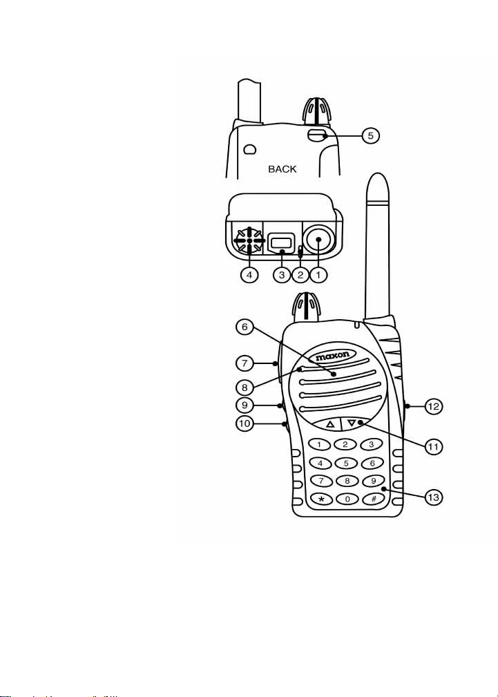
VII. Description of Radio Components
1) Antenna Receptacle
2) Busy / TX Indicator
3) LCD Channel Display
4) On/Off - Volume Control
5) Battery Latch
6) Speaker
7) Push-To-Talk (P-T-T) Bar
8) Microphone
9) Scan Button / Key 1
10) Monitor Button / Key 2
11) Channel Selection Buttons
12) Accessory Connector
13) Keypad
Not shown:
Battery Charge Contacts
Belt Clip
5
Page 10

VIII. Antenna Installation
Fasten the antenna to the radio by turning the antenna clockwise into the
receptacle on top of the radio.
IX. Installing and Removing the Battery Pack
To attach the battery pack, hold the radio face down in your hand and
position the guides of the battery in line with the radio guide rails. Slide the
battery upward until a click is heard. To remove the battery pack, hold the
radio face down in your hand and push the battery latch button located in
the upper right hand corner of the battery pack. Hold the battery latch button
down, and slide the radio battery in a downward direction. Gently lift the
battery pack away from the base of radio when it is free from the radio guide
rails.
X. Attaching and Removing the Belt Clip
To attach the clip, hold the radio face down in your hand. Locate the slot in
the belt clip and align with holder on upper left hand corner of the radio back.
Push upward on belt clip until a click is heard. To remove the clip, push and
hold the release button located at the top of the belt clip. Slide the clip away
from the belt clip holder.
XI. Battery Charging and Care
Before initial operation, use the provided charger to completely charge the
radio battery pack. Remove the charger base and power supply from the
packaging, and plug in the power supply's DC connector into a jack on
the back of the charging base. Plug the AC power cord into any standard
110V AC outlet.
To charge a battery while attached to a radio, simply place the radio into the
front charging well. The charger will identify the battery condition, and then
automatically initiate a charge mode - rapid or top-off / trickle.
To charge a battery removed from the radio, place the battery into the rear
charging well. Again, the charger will identify the battery condition, and
automatically rapid charge or top-off / trickle charge the battery pack. Note
the color of the LED charge indicators: red for rapid charge cycle, green for
the top-off / trickle charge cycle.
6
Page 11

XI. Battery Charging and Care, continued
When using both charging wells, only one can rapid charge at a time. The
front charging well always has priority for rapid charging. After the front well
cycles from rapid to top-off / trickle charge, the back well will initiate its rapid
charge mode. Again, note the color of the charging well's LED to define the
current charging cycle.
NOTE: To ensure peak performance from your radio, periodically discharge
the battery completely and recharge fully. This action will prevent the battery
from developing a "memory" of short-term use, and will permit a good service
life.
XII. SP-200K Series Operation
Many of the features of the SP-200K Series are defined by you and will have
been determined by your radio communications Dealer and yourself. Refer to
Possible Set-ups for the SP-200K Series on how your radio may have been
programmed.
Power On - Volume - Power Off
Turn the radio on by rotating the off / on - volume control clockwise. You
will hear a click and (if enabled via Dealer programming), the radio's self-test
alert tones. Increase the radio volume by continuing the clockwise rotation.
To turn the radio off when you have finished transmitting, receiving, etc.,
rotate the control counter-clockwise to detent.
Channel Select / Channel Group Scan
To change radio channels, simply press and release the I or J button
until the desired channel is reached. Or, to scroll through your programmed
channels more quickly, press and hold the I or J button. The channel
numbers will appear in the radio's LCD (located at top of unit).
If your radio has been programmed for channel group scan, you must enter
the scan mode by pressing the scan button (first button below the P-T-T bar).
The current channel group will display on the radio's LCD. If you wish to
change that selection, use the I or J button, until the LCD displays the
channel group you wish to scan.
To Transmit
NOTE: The Federal Communications Commission Rules and Regulations
require that you monitor a channel for activity before transmitting, to avoid
interrupting another user.
7
Page 12

XII. SP-200K Series Operation, continued
To Transmit, continued
Standard Transmit: Press the monitor button (second button below the
P-T-T bar) and check the color of the radio's top-panel LED. It will glow
orange if RF activity is present; it will not be illuminated if the radio indicates
a "clear" channel.
The following comments are intended to be used as a guide only, due to
the variable nature of the software and radio features.
Transmit a fixed Selcall address: A short or long press on a Call Key, either
Key 1 or Key 2 depending on set-up. Briefly the LED on the top panel
illuminates red. Conversation can begin by pressing the P-T-T button.
Transmit a variable Selcall address: A variable Selcall address may be
selected using the numerical keys (0 - 9). The number of variable digits will
be determined at programming. Pressing the * key generates the default
address (Call 1) with appended variable digits. Pressing the # key generates
the default address (Call 2) with appended variable digits.
At power-up, the radio will default to Selcall mode.
To Transmit DTMF: The radio can be programmed for DTMF transmission
only, or can be programmed to toggle between Selcall and DTMF. If
programmed with this "toggle keypad" mode, press the "toggle keypad"
key (defined at programming stage) and press the DTMF keys to transmit.
Pressing the "toggle keypad" key once more will return the keypad to Selcall
mode. In DTMF mode only, press the DTMF keys to transmit.
With all of the above features, when the channel is "clear", hold the radio
microphone area approximately 2 inches from your mouth, keeping the
antenna vertical and away from face or eyes. Press and hold the P-T-T bar
on the side of the radio, and begin speaking in a clear, normal tone. Release
the P-T-T bar when you have finished speaking.
CAUTION: Operation of the transmitter without a proper antenna installed
may result in permanent damage to the radio.
NOTE: The radio's LED will glow red continuously when you have the P-T-T
bar pressed and are transmitting. If the red LED starts "flashing", the battery
needs to be recharged and transmission will cease. Recharge the battery
fully before attempting more than one transmission.
8
Page 13

XII. SP-200K Series Operation, continued
To Receive
Flashing green LED indicates call received, and if programmed, an alert tone
is generated. Conversation can then begin by pressing the P-T-T button. LED
will continue to flash until call has been answered.
Keypad Lock / Function Lock
Your radio has the ability to lock the channel I or J buttons and scan
button to prevent accidental button presses. To lock these buttons, press
and hold the scan button (first button below the P-T-T bar) for approximately
4 seconds. The display will show "LO" and two confirmation beeps will
sound. To unlock the keypad, press and hold the scan button again for
approximately 4 seconds.
The P-T-T and monitor buttons can be locked by pressing the * and #
keys at the same time for approximately 1 second. Repeat the procedure
tounlock these buttons.
XIII. Status Indicators and Audible Alert Tones
Your SP-200K Series radio has a sophisticated microprocessor control which
provides a series of audible alert tones. Upon each power-up, a quick melody*
indicates that the self-test of the microprocessor functions has been completed.
A series of tones may be sounded with any of the following conditions:
Attempt to transmit on a channel set for receive only
Attempt to transmit on a channel that is already in use when busy channel
lockout has been programmed into the radio*
Transmitting time has exceeded time-out timer programmed length*
Low battery condition
Selecting a channel with no programmed frequency
P-T-T lockout
TX Time-out-timer
Toggling scrambler on and off
Toggling keypad on and off
Keypad alerts
Side button alerts
Decode of valid Selcall address
Auto-mute alert
* Indicates a function that is initially programmed into the radio by your Dealer.
See the Status Indicators and Audible Alert Tones chart on next page for details.
9
Page 14

XIII. Status Indicators and Audible Alert Tones, continued
STATUS DESCRIPTION LED COLOR LCD INDICATION AUDIBLE TONE
Normal Power On - Ready N /A 188 Melody
Call Received Orange Channel Number N/ A
Correct Call Green Channel Number N /A
Busy Channel Orange Channel Number N /A
Valid Selcall Decode Green Flashing Channel Number One to Three Tone
Radio Stunned N/A Channel Number Two Beeps
Radio Received N/A Channel Number Melody
Transmit Red Channel Number N/A
Transmit Not Allowed Red Flashing Alternating UL/ Two Beeps Repeated
Channel Number
Keypad Lock N/A LO Two Beeps Repeated
Scanning Normal Scan Mode Green Flashing Group Number N/ A
Priority Scan Mode Green Flashing N/A N/ A
Priority Look Back Green Flashing Lb / Channel N/ A
Scan Mode number
Scan Edit Edit Scan List Red Single Flash SE N/ A
Priority Edit Priority Channel Red Two Flashes PE N/ A
Edit
Warning Low Battery Red Flashing LC 3 Beeps Repeated
Busy Channel Lockout Orange bL Single Beep Repeated
TX Inhibit N/A _h/rO Two Beeps
Time-Out-Timer N/A Pt Single Beep/ 3 Beeps
Error EEPROM N/A Er Single Beep Repeated
Unlock N/A UL Two Beeps Repeated
Alert
Repeated
NOTE: All audible tones can be programmed "off" for silent operation.
XIV. Scan Modes
Scanning is a Dealer programmable feature that allows you to monitor a
number of channels or channels within a Group. Your radio communications
Dealer will help you define a scanning mode and your channel "scan list" .
Normal Channel Scan
Once the scan list has been established, initiate scan by pressing and
releasing the scan button (first button below the P-T-T bar).
If a conversation is detected on any of the channels in the scan list, the radio
will stop on that channel and you will be able to hear the conversation. If
programmed for normal scan TX, you will be able to transmit on that active
10
Page 15

XIV. Scan Modes, continued
Normal Channel Scan, continued
channel during the programmable scan delay time. (The scan delay time
is the amount of time the radio will stay on that channel once activity has
ceased. Dealer programmable, 4-7 seconds is typical). The radio will
resume scanning once the scan delay time has expired, and will continue
to scan until the channel is changed. The LED will flash green.
Priority Channel Scan
A single channel may be programmed as the "Priority" channel. The radio
will constantly monitor this channel while scanning and when the radio has
stopped on an active channel. If a call is detected on the priority channel,
the radio will automatically move to, and remain on, the priority channel
for as long as the priority conversation takes place. Priority channel activity
takes precedence over all other conversations. To activate the Priority scan
mode, press and release the scan button (first button below the P-T-T bar).
The LED will flash green.
XV. Other Scanning Features
Look Back
This feature is ideal for those who do not need scan as defined above, but
want to make sure that they never miss a call on the "Priority" channel if
another channel has been selected. Once a channel has been selected,
the radio will periodically "look back" at the priority channel. If activity is
detected on the priority channel, the radio will move to that channel for
as long as it remains active. To enter the "look back" mode, press and hold
the scan button (first button below the P-T-T bar). Lb / Channel number will
be shown in the display, the LED will flash green.
NOTE: Look back requires that the radio leave the current channel for a
fraction of a second (at regular intervals) to check the priority channel for
activity. Depending upon how the radio is programmed (scan speed, etc.)
this may or may not be noticeable as "breaks" on the current channel for
that same fraction of a second. A transmission will be made on the active
channel at all times.
Scan Channel Delete
To temporarily delete a channel from the scan list, simply press the monitor
button (second button below the P-T-T bar) while scanning and stopped on
the channel to be deleted. This will remove that channel from the scan list
11
Page 16

XV. Other Scanning Features, continued
Scan Channel Delete, continued
until the channel is changed or the radio's power is reset. When power is
restored or the scan list channel position is selected again, the originally
programmed scan list will be activated.
CTCSS / DCS Scanning
To help block out unwanted calls to your radio, the SP-200K Series can be
programmed by your Dealer to scan for tones.
Normal Scan TX
Allows a transmission only after a call is received, depending on the
programmed scan delay time. After scan resumes, and a transmission is
made, the radio will sound two beeps, display _h and will not allow a
transmission.
Priority Scan TX
Allows a transmission after a call is received depending on programmed
scan delay time. The transmission will be made on the channel that the call
was received. After the scan resumes, if a transmission is made, the radio
will transmit on the programmed priority channel.
Priority Only TX
Allows a transmission on the priority channel when scanning and not
stopped on an active channel. It will always transmit on the priority
channel if scanning or stopped on an active channel.
Receive Only Scan
This allows only reception, not transmission. If a transmission is made at
any time, the radio will sound two beeps, display r0 and will not allow the
transmission.
XVI. Scan List Edit
You can edit your radio's original scan list and priority scan channel at any
time. Please note, if your radio has been programmed for channel-only scan,
you will not be able to edit your scan list, only your priority channel.
Channel Group Edit
To edit the group scan list in a radio programmed for channel group scan,
turn the radio off, press and hold scan button, (first button below the P-T-T
bar). While holding scan button, turn the radio on, and observe a single
12
Page 17

XVI. Scan List Edit, continued
Channel Group Edit, continued
red flash of the LED. The display will read SE. Release the scan button.
The first group number will be displayed. If you do not wish to edit the group
you have selected press the I or J button to select the desired channel
groups you wish to edit. After channel group selection has been made,
press and release the scan button (first button below the P-T-T bar). The
channel number within your selected channel group may now be edited.
If the channel number is flashing, that channel is already included in the
scan list of the selected channel group. If the channel number is solid, the
channel can be added or deleted from the scan list. Press and release the
monitor button, (second button below the P-T-T bar), the selected channel
will flash if it was added to the scan list or be solid if it was deleted from the
scan list.
To edit other channels, press the I or J buttons to select the desired
channel within the channel group. To add or delete the newly selected
channel from the channel group scan list, repeat the process detailed
above. Upon completion of editing channels on your channel group
scan list, press and release the scan button, (first button below the P-T-T
bar). Your new channel group scan list should be entered at this time.
Priority Channel Edit
Only one priority channel can be programmed into the radio. To edit a
priority channel, turn the radio off, press and hold scan button (first
button below the P-T-T bar). While holding the scan button, turn radio on,
and release the scan button after the second red flash of the LED. PE will
be shown in the display. Release the scan button. The first channel number
will be displayed. If displayed channel is not your priority channel, press
and release the I or J button to select the desired priority channel.
After you have selected the channel, a flashing channel number indicates
that the channel is already selected as priority. If channel number is solid,
the channel is not selected as priority. To add or delete the selected channel
as the priority channel, press and release the monitor button, (second button
below the P-T-T bar). The selected channel will flash if it was added as a
priority channel or will be solid if deleted as the priority.
Upon completion of adding or deleting the priority channel, press and release
the scan button. Your new priority channel should be entered at this time.
13
Page 18

XVII. Possible Set-ups for the SP-200K Series
Check off appropriate settings below:
Power-up Alert ON ( ) OFF ( )
Scrambler On at Power-up ON ( ) OFF ( )
Scrambler On / Off Alert ON ( ) OFF ( )
Permanent Scrambler YES ( ) NO ( )
P-T-T:
P-T-T Lockout until valid Selcall YES ( ) NO ( )
Automatic Number ID (ANI) YES ( ) NO ( )
Both YES ( ) NO ( )
Keypad:
Selcall Only YES ( ) NO ( )
DTMF Only YES ( ) NO ( )
Both YES ( ) NO ( )
Key 1 - Short Press = (Press and Immediate Release):
Toggle Scrambler YES ( ) NO ( )
Call 1 YES ( ) NO ( )
Call 2 YES ( ) NO ( )
Emergency Call YES ( ) NO ( )
Group Call YES ( ) NO ( )
Stun / Revive YES ( ) NO ( )
Toggle Monitor YES ( ) NO ( )
Covert On / Off YES ( ) NO ( )
Toggle Keypad YES ( ) NO ( )
Key 1 - Long Press = (Press and Hold for 2 Seconds):
Toggle Scrambler YES ( ) NO ( )
Call 1 YES ( ) NO ( )
Call 2 YES ( ) NO ( )
Emergency Call YES ( ) NO ( )
Group Call YES ( ) NO ( )
Stun / Revive YES ( ) NO ( )
Toggle Monitor YES ( ) NO ( )
Covert On / Off YES ( ) NO ( )
Toggle Keypad YES ( ) NO ( )
14
Page 19

XVII. Possible Set-ups for the SP-200K Series, continued
Check off appropriate settings below:
Key 2 - Short Press = (Press and Immediate Release):
Toggle Scrambler YES ( ) NO ( )
Call 1 YES ( ) NO ( )
Call 2 YES ( ) NO ( )
Emergency Call YES ( ) NO ( )
Group Call YES ( ) NO ( )
Stun / Revive YES ( ) NO ( )
Toggle Monitor YES ( ) NO ( )
Covert On / Off YES ( ) NO ( )
Toggle Keypad YES ( ) NO ( )
Key 2 - Long Press = (Press and Hold for 2 Seconds):
Toggle Scrambler YES ( ) NO ( )
Call 1 YES ( ) NO ( )
Call 2 YES ( ) NO ( )
Emergency Call YES ( ) NO ( )
Group Call YES ( ) NO ( )
Stun / Revive YES ( ) NO ( )
Toggle Monitor YES ( ) NO ( )
Covert On / Off YES ( ) NO ( )
Toggle Keypad YES ( ) NO ( )
15
Page 20

XVIII. Compatible SP-200K / SP-210K Accessories
900 mAh Prismatic battery pack (QPA-900)
1350 mAh NiMH Battery pack (QPA-1350)
VHF Antenna, uncut, 148-174 MHz, SMA (ACC-102)
UHF Antenna, 440-470 MHz, 3-1/2" , SMA (ACC-100)
Dual slot / dual rate desktop charger (ACC-400K)
Ultra-lite headset with locking connector (ACC-616)
Over-the-head noise-attenuating headset (ACC-626)
(requires ACC-506 adaptor)
Behind-the-head noise-attenuating headset (ACC-627)
(requires ACC-506 adaptor )
Ear bud speaker with in-line P-T-T, microphone and
locking connector (ACC-706)
Lapel speaker microphone with ear jack and locking
connector (ACC-726)
Heavy Duty speaker microphone with audio earphone
jack (ACC-727)
Coil-cord earphone, used with ACC-727 (QPA-1424)
Ear speaker, for use with ACC-726 (WTA-9F)
Leather case with swivel (ACC-300)
Nylon case with belt clip (ACC-301)
2-pin to 1-pin Accessory adaptor (ACC-506)
XIX. FCC Licensing
The Federal Communications Commission requires the operator of this radio
be properly licensed under the applicable Part and/or Parts of the FCC Rules
and Regulations.
Consult with your radio communications Dealer, or contact the nearest FCC
field office for information about obtaining a license.
16
Page 21

XX. Service
Do not tamper with internal adjustments. Damage to the equipment and/or
improper operation may result. There are no serviceable items inside the
radio. It is recommended that you return your radio to a qualified radio
communications Dealer for any service or repairs.
XXI. Software Copyrights
The Topaz3 / Maxon product(s) described in these operating instructions
may include copyrighted Topaz3 / Maxon software programs stored in
semi-conductor memories or other media. Laws in the United States and other
countries preserve for Topaz3 / Maxon certain exclusive rights for copyrighted
software programs, including the exclusive right to copy or reproduce in any
form the copyrighted software program.
Accordingly, the copyrighted Topaz3 / Maxon software programs contained in
the Topaz3 / Maxon products described in this operating manual may not be
copied or reproduced without the express written permission of Topaz3, LLC.
Furthermore, the purchase of Topaz3 / Maxon products shall not be deemed to
grant either directly or by implication, estoppel, or otherwise, any license under
the copyrights, patents or patent applications of Topaz3, LLC, except for normal
non-exclusive, royalty-free license to use that arises by operation of law in the
sale of a product.
XXII. Maintenance
Your SP-200K Series radio is designed to be maintenance free. To keep your
radio in good working condition, follow these cleaning instructions:
Clean external surfaces with a clean cloth dampened in a solution of mild
dishwater detergent diluted in water. Apply the solution sparingly to avoid any
moisture leaking into cracks and crevices. DO NOT submerge the radio. Use
only a non-metallic brush to dislodge particles, if necessary. Dry the surface
thoroughly with a soft, lint-free cloth.
DO NOT use solvents or spirits for cleaning - they may permanently damage
the housing.
Clean the battery and accessory port contacts with a lint-free cloth to remove
dirt, grease or foreign materials that may impede good electrical contact.
17
Page 22

XXIII. Product Warranty
Topaz3, LLC (herein Topaz3), warrants each new radio product manufactured or supplied by it
to be free from defects in material and workmanship under normal use and service for the time
period listed below, provided that the user has complied with the requirements stated herein. The
Warranty period begins on the date of purchase from an Authorized Topaz3 Sales and Service
Outlet. This Warranty is offered to the original end user and is not assignable or transferable.
Topaz3 is not responsible for any ancillary equipment which is attached to or used in conjunction
with Maxon and Legacy products.
Topaz3 offers to the original end user a Two (2) Year Limited Warranty on all Maxon and Legacy
Business and Industrial Radio Products. Accessories carry a One (1) Year Limited Warranty.
During this period, if the product fails to function under normal use because of manufacturing
defect(s) or workmanship, it should be returned to the Authorized Topaz3 Sales and Service Outlet
from which it was purchased. The Sales and Service Outlet will repair the product, or return the
product for repair to Topaz3 or its Authorized Repair Depot. The user is responsible for the payment
of any charges or expenses incurred for the removal of the defective product from the vehicle or
other site of its use; for the transportation of the product to the Sales and Service Outlet; for the
return of the repaired / replacement product to the site of its use and for the reinstallation of the
product.
Topaz3 shall have no obligation to make repairs or to cause replacement required which results
from normal wear and tear or is necessitated in whole or in part by catastrophe, fault or negligence
of the user, improper or unauthorized alterations or repairs to the Product, incorrect wiring, use of
the Product in a manner for which it was not designed, or by causes external to the Product.
This warranty is void if the product serial number is altered, defaced or removed.
Topaz3's sole obligation hereunder shall be to replace or repair the Product covered in this
Warranty. Replacement, at Topaz3's option, may include a similar or higher-featured product.
Repair may include the replacement of parts or boards with functionally equivalent reconditioned
or new parts or boards. Replaced parts, accessories, batteries or boards are warranted for the
balance of the original time period. All replaced parts, accessories, batteries or boards become
the property of Topaz3.
THE EXPRESS WARRANTIES CONTAINED HEREIN ARE IN LIEU OF ALL OTHER
WARRANTIES, EITHER EXPRESSED OR IMPLIED OR STATUTORY, INCLUDING, WITHOUT
LIMITATION, ANY WARRANTY OF MERCHANTABILITY OR FITNESS FOR A PARTICULAR
PURPOSE.
FOR ANY PRODUCT WHICH DOES NOT COMPLY WITH THE WARRANTY SPECIFIED, THE
SOLE REMEDY WILL BE REPAIR OR REPLACEMENT. IN NO EVENT WILL TOPAZ3 BE
LIABLE TO THE BUYER OR ITS CUSTOMERS FOR ANY DAMAGES, INCLUDING ANY
SPECIAL, INCIDENTAL, INDIRECT OR CONSEQUENTIAL DAMAGES, OR THE LOSS OF
PROFIT, REVENUE OR DATA ARISING OUT OF THE USE OF OR THE INABILITY TO USE
THE PRODUCT.
This Warranty is void for sales and deliveries outside of the U.S.A. or Canada.
18
Page 23

Contenido
I. Requerimientos de Obediencia a la Exposición de RF del FCC -
para uso Ocupacional Solamente................................................................. 19
II. Información Sobre Seguridad......................................................................... 20
III. Acerca de Su Radio Serie SP-200K................................................................. 20
IV. Acerca de Topaz3........................................................................................... 21
V. Información para Desempacar......................................................................... 21
VI. Funciones de la Serie SP-200K....................................................................... 22
VII. Descripción de los Componentes del Radio.................................................... 23
VIII. Instalación de la Antena................................................................................... 24
IX. Cómo Instalar y Retirar el Paquete de las Baterías........................................... 24
X. Asegurar y Quitar el Clip de Cinturón............................................................. 24
XI. Cómo Cargar y Mantener la Batería................................................................. 24
XII. Funcionamiento de Serie SP-200K.................................................................. 25
Encendido - Volumen - Apagado.................................................................. 25
Selección de Canales / Búsqueda del Grupo de Canales.............................. 25
Para Transmitir.............................................................................................. 26
Para Recibir.................................................................................................. 27
Bloqueo del Teclado Numérico / Bloqueo de la Función............................ 27
XIII. Indicadores de Estado y Tonos Audibles de Alerta.......................................... 28
XIV. Modos de Búsqueda....................................................................................... 29
Búsqueda Normal de Canales...................................................................... 29
Buscar Canal Prioritario................................................................................ 30
XV. Otras Funciones de Búsqueda......................................................................... 30
Mirar Atrás.................................................................................................... 30
Cómo Borrar un Canal de la Lista de Búsqueda............................................ 31
Búsqueda CTCSS / DCS................................................................................ 31
Búsqueda TX Normal................................................................................... 31
Búsqueda TX Prioritaria................................................................................ 31
TX Prioritaria Solamente............................................................................... 31
Búsqueda para Recibir Solamente................................................................ 31
XVI. Editar la Lista de Búsqueda.............................................................................. 32
Editar el Grupo de Canales........................................................................... 32
Editar Canal Prioritario.................................................................................. 32
XVII. Disposiciones Posibles para la Serie de SP-200K............................................. 33
XVIII. Accesorios Compatibles SP-200K / SP-210K..................................................... 35
XIX. Licencia de la FCC........................................................................................... 35
XX. Servicio........................................................................................................... 35
XXI. Derechos de Autor del Software..................................................................... 36
XXII. Mantenimiento............................................................................................... 36
XXIII. Declaración de Garantía.................................................................................. 37
Page 24

I. Requerimientos de Obediencia a la Exposición de RF del
FCC - para uso Ocupacional Solamente
La Comisión Federal de Comunicaciones (FCC), con su medida en Registro
General 93-62, del 7 de noviembre de 1997, ha adoptado una norma de
seguridad para la exposición humana a la energía electromagnética de
radiofrecuencia (RF) emitida por equipo regulado por la FCC. Topaz3 / Maxon
adopta la misma norma de seguridad para el uso de sus productos. La
operación adecuada de este radio resultará en una exposición del usuario
muy inferior a los límites establecidos por el Acta de Seguridad y Salud
Ocupacional (OSHA) y la Comisión Federal de Comunicaciones.
PRECAUCIÓN - NO transmita por más de 50% del tiempo del uso total
del radio (ciclo de trabajar de 50%). Transmitiendo más
del 50% del tiempo puede causar que los requisitos del
RF del FCC de la conformidad de la exposición sean
excedido.
• El radio NO esta aprobado por uso por la población general en un
ambiente libre. Esta radio está restringido al uso ocupacional, a las
operaciones relacionadas al trabajo solamente donde el operador de
radio debe tener el conocimiento para controlar las condiciones de la
exposición del usuario para satisfacer el límite más alto de exposición
permitido para el uso ocupacional.
• Cuando transmite, sostenga el radio en una posición vertical con su
micrófono 5 cm lejos de su boca.
• Este disposition se ha probado para usar como un factor de función
máxima del 50%, usando el eclip del cinturón y estuche de cuero
específico para usar en el cuerpo; probado en conformidad con la
organización SAR. Otros clips del cinturón o accesorios para usar en
el cuerpo pueden no conformarse y deben ser evitados.
• El radio transmite cuando el diodo luminoso se ilumina rojo en el frente
del radio. Presionando el conmutador de P-T-T en del radio causa el radio
a transmitir.
• Estas son configuraciones de funcionamiento requeridas para la
conformidad de la reunión de exposición de la FCC RF. Incumplimiento
de observar estas restricciones, significa violación.
19
Page 25

II. Información Sobre Seguridad
ADVERTENCIA - NO sostenga el radio de manera tal que la antena esté junto
a, o toque, partes expuestas del cuerpo, especialmente la cara o
los ojos, mientras transmite.
ADVERTENCIA - NO permita que los niños operen este equipo de radio
equipado con transmisor.
PRECAUCIÓN - NO opere el radio cerca de cápsulas eléctricas no
protegidas o en una atmósfera explosiva a menos que sea
un tipo especialmente diseñado y apto para dicho uso.
PRECAUCIÓN - NO oprima y sostenga el interruptor de transmisión (P-T-T)
cuando no desee transmitir.
III. Acerca de Su Radio Serie SP-200K
Radios sintetizads con teclado numérico de DTMF SP-200K (VHF) y SP-210K
(UHF) de Maxon ofrecen hasta 13 grupos de búsqueda con hasta 16 canales
por grupo, lo que compone una capacidad total de 199 canales.
Para lograr un funcionamiento satisfactorio de su radio, le recomendamos
que lea cuidadosamente las información sobre operación y funciones que
ofrece este manual antes de hacer funcionar su radio Serie SP-200K.
La aplicaciones de algunas de las funciones descritas en este manual son
determinadas por el sistema que use. Su distribuidor de comunicaciones por
radio programará su radio para que logre el mayor número de funciones
posibles en relación con sus necesidades.
Si tiene alguna pregunta con respecto al funcionamiento del radio, por favor
acuda a su distribuidor de comunicaciones por radio.
20
Page 26

IV. Acerca de Topaz3
Topaz3 es el suplidor exclusivo de las marcas de productos Maxon®, Legacy
y TruTalk.
Nuestra línea de productos alcanza desde radios de dos vías convenientes
para mercados de Negocios e Industrias (B & I) tales como granjas o fincas,
gobierno, personal que ejecuta la ley, servicio público, etc. a equipos para
comunicaciones del consumidor para uso de mercados recreacionales y de
negocios con funciones livianas.
Los productos incluyen una variedad de radios portátiles y móbiles de UHF
y VHF, repetidoras y módulos de RF Link, tanto como Radios de Servicio
Familiar (FRS), Servicio General de Radios Móbiles (GMRS), Multi Servicio
de Radio del Utilizador (MURS), Radios de Banda Ciudadana y monitores
del tiempo.
Items de accesorios disponibles incluyen una variedad de estuches para
cargar los radios, baterías, cargadores de escritorios y móbiles, micrófonos
parlantes de oído y más para cada modelo de radio.
Para información adicional de los productos de Topaz3, visite nuestro website
en www.topaz3.com
V. Información para Desempacar
Retire e inspeccione cuidadosamente el contenido de la/s caja/s para verificar
que contenga los siguientes elementos:
Radio
Paquete de baterías
Cargador de baterías
Fuente de alimentación para el cargador de batería
Antena
Clip de cinturón
Instrucciones de Funcionamiento
Si faltara cualquiera de estos elementos, comuníquese con el distribuidor
de comunicaciones por radio a quien compró los radios, o consulte al
departmento de Servicios al Cliente de Topaz3 al 1-816-891-6320, extensión
499 o 1-800-821-7848, extensión 499.
21
Page 27

VI. Funciones de la Serie SP-200K
Funcionamiento sintetizado con capacidad para 199 (13 grupos de
búsqueda con hasta 16 canales por grupo)
Potencia de salida programable de 1 o 5 W (Vatios)
Espaciador de canal de 12,5 /20 /25 kHz programable
Formato de multi-tono Selcall
Sets de tonos completamente programables - incluyendo EEA, CCIR y ZVEI
Identificación automática del número en el P-T-T
Codificador de DTMF
Teclado numérico dual de la función
Llamada de emergencia
Atonte y restablezca
Llamada de grupo
Claves definibles del programador
Modos opcionales de la pena y temporización del P-T-T
Modo de operación secreto
Incorporado inversión de desmodulador
Transmisión del estatus
Tonos indicadores CTCSS / DCS
Búsqueda de canal
Búsqueda de canal prioritario
Canal de búsqueda hacia atrás
Reloj de suspensión temporal
Edición de lista de búsqueda
Edición del canal prioritario
Traba de canales ocupados
Pantalla LCD de canales
Despligue de una luz tri-color
Chasis de aluminio con caja de polycarbonato
22
Page 28

VII. Descripción de los Componentes del Radio
1) Receptáculo de la Antena
2) Indicador de Ocupado/ TX
3) Pantalla LCD de Canales
4) Encendido - Apagado -
Control de Volumen
5) Traba de las Batería
6) Altavoz
7) Barra P-T-T (Push-To-Talk)
de Presionar-Para-Hablar
8) Micrófono
9) Botón de Scan (busqueda)
Clave 1
10) Botón de Monitor
Clave 2
11) Botónes de Selección
de Canales
12) Conector Accesorio
13) Teclado Numérico
No mostrados:
Contactos para Cargar
la Batería
Clip para Cinturón
23
Page 29

VIII. Instalación de la Antena
Conecte la antena al radio girándola en el sentido de las manecillas del reloj
en el receptáculo ubicado en la parte superior del radio.
IX. Cómo Instalar y Retirar el Paquete de las Batería
Para instalar el paquete de las baterías, sostenga el radio hacia abajo en la
mano y alinee las guías de la batería con las barras de guía del radio. Deslice
la batería hacia arriba hasta oír un chasquido. Para retirar el paquete de la
batería, sostenga el radio apuntando hacia abajo en la mano y oprima el
botón de traba de la batería ubicado en la esquina superior derecha del
paquete de la batería. Mantenga oprimido el botón de traba de la batería y
deslice la batería en dirección hacia abajo. Con cuidado levante el paquete
de la batería fuera de la base del radio una vez que se haya liberado de las
barras de guía.
X. Asegurar y Quitar el Clip de Cinturón
Para asegurar el clip, sostenga el radio hacia abajo en la mano. Ubique la
ranura en el clip de cinturón y alinee con el sujetador situado en la esquina
superior izquierda en la parte posterior del radio. Empuje hacia arriba sobre
el clip de cinturón hasta que oiga un chasquido. Para quitar el clip, oprima y
sostenga el botón para soltarlo en la parte superior del clip. Deslice el clip del
sujetador de clip de cinturón.
XI. Cómo Cargar y Mantener la Batería
Antes de usar el radio, use el cargador de batería provisto para cargar
completamente el paquete de la batería. Retire la base del cargador y el
enchufe de alimentación eléctrica del empaque, y enchufe el conector de
CC en el jack ubicado en la parte trasera de la base del cargador. Enchufe
el cable de alimentación de CA en un enchufe estándar de 110V CA.
Para cargar una batería mientras está instalada en el radio, simplemente
coloque el radio en el receptáculo de carga posterior. El cargador detectará
el estado de la batería y automáticamente la cargará por medio de carga rápida
o completa / gradual.
Para cargar una batería fuera del radio, coloque la batería en el receptáculo
cargador posterior. Nuevamente, el cargador detectará el estado de la batería y
automáticamente lo cargará por medio de carga rápida o completa / gradual.
Observe el color de los indicadores LED de carga: rojo indica el ciclo de carga
rápida, verde el ciclo de carga completa / gradual.
24
Page 30

XI. Cómo Cargar y Mantener la Batería, continuación
Cómo Cargar y Mantener la Batería, continuación
Cuando use ambos receptáculos de carga, sólo uno puede efectuar la carga
rápida a la vez. El cargador frontal siempre tiene prioridad para la carga rápida.
Después que el receptáculo frontal pasa de carga rápida a completa / gradual,
el receptáculo posterior iniciará su modo de carga rápida. Nuevamente,
observe el color del receptáculo de carga en el LED para definir el ciclo de
carga en curso.
NOTA: Para asegurar el rendimiento óptimo de su radio, periódicamente
descargue completamente la batería y vuelva a cargarla por completo. Esto
evitará que la batería desarrolle una "memoria" de uso breve y permitirá
obtener una buena vida útil.
XII. Funcionamiento de Serie SP-200K
Muchas de las características del SP-200K son definidas por usted y habrán
sido determinadas por su distribuidor de comuncaciones por radio y usted
mismo. Refiera a las disposiciones "Disposiciones Posibles para la Serie
de SP-200K" en cómo su radio pudo haber sido programada.
Encendido - Volumen - Apagado
Encienda el radio girando el control de encendido / apagado - volumen
en el sentido de las manecillas del reloj. Oirá un chasquido (si está
activado por la programación del Distribuidor), y los tonos de alerta de
autoprueba del radio. Aumente el volumen del radio girando en sentido
de las manecillas del reloj. Para apagar el radio después de transmitir,
recibir, etc., gire el control en el sentido contrario hasta que se detenga.
Selección de Canales / Búsqueda del Grupo de Canales
Para cambiar los canales de radio, simplemente oprima y suelte el botón I
o Jhasta encontrar el canal deseado. O bien, para pasar por sus canales
programados más rápidamente, oprima y sostenga el botón I o J. Los
números de los canales aparecen en la pantalla LCD del radio (ubicada en
la parte superior de la unidad).
Si su radio ha sido programado para buscar grupos de canales, usted debe
ingresar el modo búsqueda oprimiendo el botón de scan (búsqueda; el
primer botón debajo de la barra P-T-T). Aparecerá el grupo de canales
programado en la pantalla del radio. Si desea cambiar dicha selección,
use el botón I o J, hasta que la pantalla muestre el grupo de canales
que desea buscar.
25
Page 31

XII. Funcionamiento de Serie SP-200K, continuación
Para Transmitir
NOTA: Las Normas y Regulaciones de la Comisión Federal de
Comunicaciones exigen que usted monitoree el canal para ver si
hay actividad antes de transmitir, para evitar interrumpir a otro usuario.
Transmisión Estándar: Oprima el botón de monitor (segundo botón
debajo de la barra P-T-T) y observe el color del LED en el panel superior del
radio. Se iluminará en color naranja si hay actividad presente; si el canal está
libre no se iluminará.
Los comentarios siguientes se propuestos para ser utilizados como una
guía solamente, debido a la naturaleza variable de las características del
software y del radio.
Transmita un direccionamiento fijo de Selcall: Una presión corta o larga en
una llamada clave, cualquiere que se a de búsqueda (Clave 1) o el botón de
monitor (Clave 2), dependiendo de la disposición. El LED brevemente en el
panel superior ilumina rojo. La conversación puede comenzar presionando
el botón del P-T-T.
Transmita un direccionamiento variable de Selcall: Un direccionamiento
variable de Selcall se puede seleccionar usando los claves numérico (0-9).
El número de dígitos variables será determinado por la programación.
Presionando * la clave genera el direccionamiento del valor por defecto
(Llamada 1) con los dígitos variables añadidos al final del fichero. El
presionar # * la clave genera el direccionamiento del valor por defecto
(Llamada 2) con los dígitos variables añadidos al final del fichero.
En el ciclo inicial, el radio omitirá el modo de Selcall.
Para Transmitir DTMF: El radio se puede programar para la transmisión
de DTMF solamente, o se puede programar para accionar la palanca
entre Selcall y DTMF. Si está programado con este modo "toggle
keypad" (interruptor del teclado), presione la clave definido en la etapa
de programación y presione la clave de DTMF para transmitir. Presionando
la clave de "toggle keypad" (interruptor del teclado) una vez más volverá el
teclado numérico al modo de Selcall. En modo de DTMF solamente,
presione los claves de DTMF para transmitir.
26
Page 32

XII. Funcionamiento de Serie SP-200K, continuación
Para Transmitir, continuación
Con todas las características anteriores, cuando el canal esté "clear" (no
esté en uso), sostenga el micrófono del radio aproximadamente 2 pulgadas
de su boca, manteniendo la antena vertical y alejada de cara y de ojos.
Presione y sostenga la barra del P-T-T en el lado del radio, y comience a
hablar en un tono claro, normal. Suelte la barra del P-T-T cuando usted
haya terminado de hablar.
PRECAUCIÓN: Operar el transmisor sin una antena correctamente instalada
puede producir daños permanentes al radio.
NOTA: El LED del radio se iluminará en rojo contínuamente mientras
esté oprimida la barra P-T-T y esté transmitiendo. Si el LED rojo comienza
a "destellar", es porque se necesita cargar la pila y cesará la transmisión.
Recargue la pila completamente antes de intentar hacer más de una
transmisión.
Para Recibir
Cuando la pantalla esta destellando verde significa llamada recibida y si
es programada, un tono de alerta es generado. La conversación entonces
puede comenzar presionando el botón del P-T-T. La pantalla continuará
destellando hasta que la llamada haya sido contestada.
Bloqueo de la Función / Bloqueo del Teclado Numérico
Su radio tiene la habilidad de cerrar con llave los botónes I o J del canal
y el botón de búsqueda para prevenir presiones accidentales del botón.
Para cerrar con llave estas botónes, presione y sostenga el botón de scan
(búsqueda; el primer botón de abajo del conmutador del P-T-T) por
aproximadamente 4 segundos. El despliegue mostrará "LO" y oirá dos
pitidos de confirmación. Para abrir el teclado, presione y sostenga de
nuevo el botón de búsqueda por aproximadamente 4 segundos.
Los botones del P-T-T y del monitor pueden ser bloqueados presionando
las claves * y # al mismo tiempo por aproximadamente un segundo. Repetir
el procedimiento para desbloquear el teclado.
27
Page 33

XIII. Indicadores de Estado y Tonos Audibles de Alerta
Su radio Serie SP-200K contiene un sofisticado control con microprocesador
el cual provee una serie de tonos audibles de alerta. Cada vez que se
encienda, se oirá una rápida melodía* que indica que se ha llevado a cabo
la autoprueba de las funciones del microprocesador. Se pueden oír una serie
de tonos ante cualquiera de las siguientes condiciones:
Se intenta transmitir en un canal programado sólo para recibir
Se intenta transmitir en un canal que ya está en uso cuando se ha
programado la traba de canales ocupados en el radio*
El tiempo de transmisión ha excedido la duración del reloj de suspensión
temporal programado*
Poca carga de la batería
Se selecciona un canal sin frecuencia programada
Bloqueo del P-T-T
Temporizador del transmisor (TX)
Encender y apagar el interruptor de scrambler
Encender y apagar el interruptor del teclado
Alerta del teclado
Alertas de los botones del lado del radio
Descodificador de la dirección válida de llamada selectiva
Alerta Auto-silencio
* Indica una función que fue inicialmente programada en el radio por su
distribuidor de radio comunicaciones.
Vea los carta Indicadores de Estado y Tonos Audibles de Alerta en la
paginación siguiente para el detalle completo.
28
Page 34

XIII. Indicadores de Estado y Tonos Audibles de Alerta, continuación
ESTADO DESCRIPCIÓN COLOR DEL LED INDICADOR EN LCD TONO AUDIBLE
Normal Encendido-Listo N/C 188 Melodía
Llamada recibida Naranja Número de Canal N/C
Llamada correcta Verde Número de Canal N/C
Canal ocupado Naranja Número de Canal N/C
Descodificador Válido de Verde Destellante Número de Canal Uno a Tres Tonos
Llamada Selectiva (Selcall) de Alerta
Radio Bloqueado N/C Número de Canal 2 Silbidos
Radio Recibido N/C Número de Canal Melodía
Transmitir Rojo Número de Canal N/C
No se Permite Rojo Destellante UL / Número de 2 Silbidos Repetidos
Transmitir Canal Alternantes
Cierre del Teclado N/C LO 2 Silbidos Repetidos
Búsqueda Modo de Búsqueda Normal Verde Destellante Número de Grupo N/C
Modo de Búsqueda Verde Destellante N/C N/C
de Canal Prioritario
Modo de Búsqueda de Canal Verde Destellante Lb / Número N/C
Prioritario Hacia Atrás de Canal
Edición de Editar Lista de Búsqueda Un Solo Destello SE N/C
Búsqueda Rojo
Edición de Editar Canal Prioritario Dos Destellos PE N/C
Prioridad Rojos
Advertencia Poca Pila Rojo Destellante LC 3 Silbidos Repetidos
Traba de Canales Naranja bL 1 Silbido Repetido
Ocupados
Inhibir TX N/C _h/rO 2 Silbidos
Reloj de Suspensión N/C Pt 1 Silbido / 3 Silbidos
Temporal Repetidos
Error EEPROM N/C E r 1 Silbido Repetido
Destrabar N/C UL 2 Silbidos Repetidos
NOTA: Todos los tonos audibles pueden programarse a
"desactivados" para un funcionamiento silencioso.
XIV. Modos de Búsqueda
La búsqueda es una función programable por el Distribuidor que le permite
monitorear una serie de canales o ciertos canales dentro de un grupo. Su
distribuidor de comunicaciones por radio le ayudará a definir su modo de
búsqueda y su "lista de búsqueda" de canales.
Búsqueda Normal de Canales
Una vez que se ha establecido la lista de búsqueda, comience a buscar
29
Page 35

XIV. Modos de Búsqueda, continuación
Búsqueda Normal de Canales, continuación
oprimiendo y soltando el botón de scan (búsqueda; primer botón debajo
de la barra P-T-T).
Si se detecta una conversación en alguno de los canales de la lista de
búsqueda, el radio se detendrá en ese canal y usted podrá oír esa
conversación. Si está programado para búsqueda TX normal, usted podrá
transmitir en ese canal activo durante el tiempo de espera de búsqueda
programable. (El tiempo de espera para buscar es el tiempo que el radio
permanecerá en ese canal una vez que ha cesado la actividad. Programable
por el Distribuidor, lo típico es de 4 a 7 segundos). El radio reanudará la
búsqueda una vez que haya finalizado el tiempo de espera para buscar,
y continuará buscando hasta que se haya cambiado de canal. El LED
destellará en verde.
Buscar Canal Prioritario
Se puede programar un solo canal como canal "prioritario". El radio
monitoreará constantemente este canal mientras busca y cuando el radio
se haya detenido en un canal activo. Si se detecta una llamada en el canal
prioritario, el radio automáticamente pasará al canal prioritario y se detendrá
en éste mientras dure la conversación en el prioritario. La actividad en el
canal prioritario tiene precedencia sobre todas las demás conversaciones.
Para activar el modo de búsqueda prioritario, oprima y suelte el botón de
scan (búsqueda; primer botón debajo de la barra P-T-T). El LED destellará
en verde.
XV. Otras Funciones de Búsqueda
Mirar Atrás
Esta función es ideal para quienes no necesitan buscar como se explica
arriba, pero desean asegurarse de no perderse una llamada en el canal
de "prioridad" si se ha seleccionado otro canal. Una vez que un canal ha
sido seleccionado, el radio periódicamente "mirará atrás" el canal prioritario.
Si se detecta actividad en el canal prioritario, el radio pasará a ese canal
mientras éste permanezca activo. Para ingresar al modo "mirar atrás",
oprima y sostenga el botón de scan (búsqueda; primer botón debajo de
la barra P-T-T). El Lb / Número de canal aparecerá en la pantalla, y el LED
destellará en verde.
NOTA: La función de mirar atrás requiere que el radio deje el canal
30
Page 36

XV. Otras Funciones de Búsqueda
Mirar Atrás, continuación
actual por una fracción de segundo (a intervalos regulares) para controlar
si hay actividad en el canal prioritario. Según como esté programado el radio
(velocidad de búsqueda, etc.) esto puede no detectarse como "interrupciones"
en el canal en uso por esa fracción de segundo. Se transmitirá en el canal
activo todo el tiempo.
Cómo Borrar un Canal de la Lista de Búsqueda
Para borrar temporalmente un canal de la lista de búsqueda, simplemente
oprima el botón de monitor (segundo botón debajo de la barra P-T-T)
mientras busca y deténgase en el canal que desea borrar. Esto borrará
dicho canal de la lista de búsqueda hasta que se cambie de canal o se
vuelva a encender el radio. Cuando se restablece la alimentación eléctrica
o se selecciona nuevamente la posición de la lista de búsqueda, se activará
la lista de búsqueda programada originalmente.
Búsqueda CTCSS / DCS
Para poder bloquear llamadas no deseadas a su radio, el radio Serie SP-200K
puede ser programado por su Distribuidor para que busque tonos.
Búsqueda TX Normal
Permite realizar una transmisión sólo después de recibir una llamada,
dependiendo del tiempo de espera para buscar que ha sido programado.
Una vez reanudada la búsqueda, y efectuada una transmisión, el radio
emitirá dos silbidos, aparecerá _h y no permitirá transmitir.
Búsqueda TX Prioritaria
Permite realizar una transmisión en el canal prioritario al buscar y no se
detiene en un canal activo. Siempre transmitirá en el canal prioritario si se
busca o detiene en un canal activo.
TX Prioritaria Solamente
Permite realizar una transmisión en el canal prioritario al buscar y no se
detiene en un canal activo. Siempre transmitirá en el canal prioritario si se
busca o detiene en un canal activo.
Búsqueda para Recibir Solamente
Esto permite sólo la recepción, no la transmisión. Si se realiza una
transmisión en cualquier momento, el radio emitirá dos silbidos,
aparecerá r0 y no permitirá transmitir.
31
Page 37

XVI. Editar la Lista de Búsqueda
Puede editar la lista de búsqueda original de su radio y el canal prioritario
en cualquier momento. Sírvase notar que si su radio ha sido programado
para la búsqueda de canales solamente, no podrá editar su lista de búsqueda,
sólo su canal prioritario.
Editar el Grupo de Canales
Para editar la lista de búsqueda de grupos en un radio programado para
buscar grupos de canales, apague el radio, oprima y sostenga el botón de
scan (búsqueda; primer botón debajo de la barra P-T-T). Mientras sostiene
oprimido el botón de scan, encienda el radio, y observe si hay un único
destello rojo del LED. La pantalla indicará SE. Suelte el botón de scan.
El número del primer grupo aparecerá en pantalla. Si no desea editar el grupo
que ha seleccionado, oprima el botón I o J para seleccionar los grupos
de canales que desea editar. Una vez seleccionado un grupo, oprima y suelte
el botón de scan (búsqueda; primer botón debajo de la barra P-T-T). Ahora
puede editar el número de canal dentro de su grupo de canales seleccionado.
Si el número de canal está destellando, dicho canal ya está incluido en la lista
de búsqueda del grupo de canales seleccionado. Si el número del canal es
continuo, el canal puede ser agregado o eliminado de la lista de búsqueda.
Oprima y suelte el botón de monitor (segundo botón debajo de la barra
P-T-T), el canal seleccionado destellará si fue agregado a la lista de búsqueda
o será continuo si fue borrado de la lista de búsqueda.
Para editar otros canales, oprima los botones I o J para seleccionar el canal
deseado dentro del grupo de canales. Para agregar o borrar el canal que
acaba de seleccionar de la lista de búsqueda del grupo de canales, repita el
proceso explicado arriba. Cuando termine de editar los canales de su lista
de búsqueda del grupo, oprima y suelte el botón de scan (búsqueda; primer
botón debajo de la barra P-T-T). En ese momento deberá ingresar su nueva
lista de búsqueda del grupo de canales.
Editar Canal Prioritario
Se puede programar un solo canal prioritario en el radio. Para editar un
canal prioritario, apague el radio, oprima y sostenga el botón de scan
(primer botón debajo de la barra P-T-T). Mientras mantiene oprimido el
botón de scan, encienda el radio, y suelte el botón de scan después que
el LED destelle en rojo por segunda vez. Aparecerá PE en la pantalla. Suelte
el botón de scan. Aparecerá el número del primer canal. Si el canal mostrado
32
Page 38

XVI. Editar la Lista de Búsqueda, continuación
Editar Canal Prioritario, continuación
no es su canal prioritario, oprima y suelte el botón I o J para seleccionar
el canal prioritario deseado. Una vez que haya seleccionado el canal, un
número de canal destellando indicará que el canal ya ha sido seleccionado
como prioridad. Si el número del canal aparece continuo, dicho canal
no está seleccionado como prioridad. Para agregar o borrar el canal
seleccionado como canal prioritario, oprima y suelte el botón de monitor
(segundo botón debajo de la barra P-T-T). El canal seleccionado destellará
si fue agregado como canal prioritario o será continuo si fue borrado como
prioridad.
Al terminar de agregar o borrar el canal prioritario, oprima y suelte el botón
de búsqueda. Deberá ingresar su nuevo canal prioritario en este momento.
XVII. Disposiciones Posibles para la Serie de SP-200K
Controle apagado las configuraciones apropiadas abajo:
Alerta de Encendido ENCENDER ( ) APAGAR ( )
Encender Scrambler ENCENDER ( ) APAGAR ( )
Alerta de Encender y Apagar el Scrambler
(Desmodulador) del Radio ENCENDER ( ) APAGAR ( )
Scrambler Permanente SÍ ( ) NO ( )
P-T-T:
Cierre del P-T-T Hasta Una Válida Llamada
Selectiva (Selcall) SÍ ( ) NO ( )
Automático Número de ID (ANI) SÍ ( ) NO ( )
Ambos SÍ ( ) NO ( )
Teclado Numérico:
Llamada Selectiva (Selcall) Solamente SÍ ( ) NO ( )
Solamente DTMF SÍ ( ) NO ( )
Ambos SÍ ( ) NO ( )
Clave 1- Presión Corta = (Presione y Suelte de Inmediato):
Interruptor de Scrambler SÍ ( ) NO ( )
Llamada 1 SÍ ( ) NO ( )
Llamada 2 SÍ ( ) NO ( )
Llamada de Emergencia SÍ ( ) NO ( )
Llamada de Grupo SÍ ( ) NO ( )
Atonte y Restablezca SÍ ( ) NO ( )
Monitor de Interruptor SÍ ( ) NO ( )
Encender y Apagar Señal Secreta SÍ ( ) NO ( )
Interruptor del Teclado SÍ ( ) NO ( )
33
Page 39

XVII. Disposiciones Posibles para la Serie de SP-200K, continuación
Controle apagado las configuraciones apropiadas abajo:
Clave 1 - Presión Larga = (Presione y Sostenga por Dos Segundos):
Interruptor de Scrambler SÍ ( ) NO ( )
Llamada 1 SÍ ( ) NO ( )
Llamada 2 SÍ ( ) NO ( )
Llamada de Emergencia SÍ ( ) NO ( )
Llamada de Grupo SÍ ( ) NO ( )
Atonte y Restablezca SÍ ( ) NO ( )
Monitor de Interruptor SÍ ( ) NO ( )
Encender y Apagar Señal Secreta SÍ ( ) NO ( )
Interruptor del Teclado SÍ ( ) NO ( )
Clave 2 - Presión Corta = (Presione y Suelte de Inmediato):
Interruptor de Scrambler SÍ ( ) NO ( )
Llamada 1 SÍ ( ) NO ( )
Llamada 2 SÍ ( ) NO ( )
Llamada de Emergencia SÍ ( ) NO ( )
Llamada de Grupo SÍ ( ) NO ( )
Atonte y Restablezca SÍ ( ) NO ( )
Monitor de Interruptor SÍ ( ) NO ( )
Encender y Apagar Señal Secreta SÍ ( ) NO ( )
Interruptor del teclado SÍ ( ) NO ( )
Clave 2 - Presión Larga = (Presione y Sostenga por Dos Segundos):
Interruptor de Scrambler SÍ ( ) NO ( )
Llamada 1 SÍ ( ) NO ( )
Llamada 2 SÍ ( ) NO ( )
Llamada de Emergencia SÍ ( ) NO ( )
Llamada de Grupo SÍ ( ) NO ( )
Atonte y Restablezca SÍ ( ) NO ( )
Monitor de Interruptor SÍ ( ) NO ( )
Encender y Apagar Señal Secreta SÍ ( ) NO ( )
Interruptor del Teclado SÍ ( ) NO ( )
34
Page 40

XVIII. Accesorios Compatibles SP-200K / SP-210K
Paquete de batería de 900 mAh Prismatic (QPA-900)
Paquete de batería de 1350 mAh NiMH (QPA-1350)
VHF Antena, 148-174 MHz, SMA (ACC-102)
UHF Antena, 440-470 MHz, 3-1/2 (ACC-100)
Caragador de sobremesa smart doble espacio / tasa dual (ACC-400K)
Receptor de cabeza de ultra-lite con conector el bloquer (ACC-616)
Audífono que se coloca alrededor de la cabeza para cancelar los ruidos
de afuera (ACC-626) (requiere el adaptador ACC-506)
Audífono que se coloca detras de la cabeza para cancelar los ruidos
de afuera (ACC-627) (requiere el adaptador ACC-506)
Micrófono parlante de oído con conector el bloquer (ACC-706)
Micrófono parlante del altavoz de la solapa con conector el bloquer
(ACC-726)
Micrófono parlante resistente con enchufe de auricular (ACC-727)
Audífono con cordon usado con ACC-727 (QPA-1424)
Parlante de oído para el uso con ACC-726 (WTA-9F)
Estuche de cuero (ACC-300)
Estuche de nylon (ACC-301)
Adaptador de 2-pin to 1-pin (ACC-506)
XIX. Licencia de la FCC
La Comisión Federal de Comunicaciones requiere que el operador de este
radio tenga la licencia pertinente conforme a la/s Parte/s de las Normas y
Reglamentaciones de la FCC correspondientes.
Consulte con su distribuidor de radio comunicaciones, o con la oficina
regional más cerca de la FCC para recibir información sobre cómo obtener
una licencia.
XX. Servicio
No altere los ajustes internos. Esto podría causar que el equipo se dañe
o no funcione bien. No hay elementos reparables en el interior del radio.
Se recomienda que lleve el radio a un distribuidor de radio comunicaciones
por cualquier servicio o reparación.
35
Page 41

XXI. Derechos de Autor del Sozftware
El/los producto/s Topaz3 / Maxon descrito/s en estas instrucciones de
funcionamiento pueden incluir programas de software de Topaz3 / Maxon
que poseen derechos de autor (copyright) almacenados en memorias de
semi-conductor o en otros medios. Las leyes de los Estados Unidos y otros
países preservan ciertos derechos de exclusividad de Topaz3 / Maxon para
los programas de software con derechos de autor, incluyendo el derecho
de exclusividad de copiar o reproducir en cualquier forma el programa de
software con derechos de autor.
En concordancia, los programas de software Topaz3 / Maxon con derechos
de autor contenidos en los productos Topaz3 / Maxon descritos en este
manual de funcionamiento no pueden ser copiados ni reproducidos sin
el permiso expreso por escrito de Topaz3, LLC.
Asimismo, la compra de productos Topaz3 / Maxon no se considerará que
otorga ni directamente ni por implicación, exclusión, o de otro modo, ninguna
licencia bajo los derechos de autor, patentes o solicitudes de patente de
Topaz3, LLC, excepto para la licencia libre de regalías no exclusiva normal
para el uso que surge de la aplicación de la ley en la venta de un producto.
XXII. Mantenimiento
Su radio Serie SP-200K ha sido diseñada para no requerir mantenimiento.
Para mantener su radio en buenas condiciones de funcionamiento, siga
estas instrucciones de limpieza:
Limpie las superficies externas con un paño limpio humedecido en una
solución de detergente de vajilla suave diluido en agua. Aplique poca cantiad
de solución para evitar que penetre humedad a través de rajaduras y
hendiduras. NO sumerja el radio. Use solamente un cepillo no metálico
para despegar partículas, si fuera necesario. Seque la superficie completamente
con un paño suave libre de pelusa.
NO use solventes ni alcohol para limpiarlo - podrían dañar
permanentemente la carcasa.
Limpie la batería y los contactos del conector accesorio con un paño libre
de pelusa para eliminar toda suciedad, grasa o materiales extraños que
pudieran impedir un contacto eléctrico adecuado.
36
Page 42

XXIII. Declaración de Garantía
La declaración Topaz3, LLC (adjunto Topaz3), autorizaciones de la garantía cada producto de radio
nuevo fabricado o provisto por ella para estar libre de defectos en material y mano de obra bajo uso
y servicio normales para el período enumeró abajo, a condición de queel utilizador se ha conformado
con los requisitos indicados adjunto. El período de la garantía comienza la fecha de la compra de las
ventas un Topaz3 y del tomacorriente para servicio autorizados. Esta garantía se ofrece al utilizador
original del extremo y no es asignable o tranferible. Topaz3 no es responsable de ningún equipo
auxiliar a el cual se asocie o se utilice conjuntamente con los productos de Maxon y Legacy.
Topaz3 ofrece al utilizador original del extremo (2) una garantía limitada año dos en todo el negocio
de Maxon y de la Legacy y productos de radio industriales. Los accesorios llevan un (1) una
garantía limitada año.
Durante este período, si el producto no puede funcionar bajo uso normal debido a defect(s) o mano
de obra de fabricación, debe ser vuelto a las ventas Topaz3 y al tomacorriente para servicio
autorizados de los cuales fue comprado. Las ventas y el tomacorriente para servicio repararán el
producto, o vuelva el producto para la reparación a Topaz3 o a su depósito autorizado de la
reparación. El utilizador es responsable del pago de cualesquiera cargas o costo incurrido en para
el retiro del producto defectuoso del vehículo o del otro sitio de su uso; para el transporte del producto
a las ventas y al tomacorriente para servicio; para la vuelta del reparada/del producto de reemplazo
al sitio de su uso y para la reinstalación del producto.
Topaz3 no tendrá ninguna obligación de reparar o de causar el reemplazo requerido que resulta de
desgaste normal y del rasgón ni es hecho necesario en entero o en parte por catástrofe, el incidente
o la negligencia del utilizador, de las alteraciones incorrectas o desautorizadas o de las reparaciones
al producto, cableado incorrecto, uso del producto de una manera para la cual no fue diseñado, o
por las causas externas al producto. Esta garantía es vacío si se altera, se desfigura o se quita el
número de serie del producto.
La obligación única de Topaz3's abajo será substituir o reparar el producto cubierto en esta
garantía. El reemplazo, en la opción de Topaz3's, puede incluir un producto similar o alto-ofrecido.
La reparación puede incluir el reemplazo de partes o de tarjetas con las piezas funcionalmente
equivalentes o las tarjetas reacondicionadas o nuevas. Autorizan las piezas, los accesorios, las
baterías o a las tarjetas substituidas para el equilibrio del período original. Todas las piezas,
accesorios, baterías o tarjetas substituidas se convierten en la característica de Topaz3.
LAS GARANTÍAS EXPRESAS CONTENIDAS ADJUNTO ESTÁN EN LUGAR DE EL RESTO
DE LAS GARANTÍAS, EXPRESADAS O IMPLICADAS O ESTATUTARIAS, INCLUYENDO,
SIN LA LIMITACIÓN, CUALQUIER GARANTÍA DEL MERCHANTABILITY O APTITUD PARA
UN PROPÓSITO DETERMINADO.
PARA CUALQUIER PRODUCTO QUE NO SE CONFORME CON LA GARANTÍA
ESPECIFICADA, EL REMEDIO ÚNICO SERÁ REPARACIÓN O REEMPLAZO. EN NINGUNA
VOLUNTAD DEL ACONTECIMIENTO TOPAZ3 SEA OBLIGADO AL COMPRADOR O A SUS
CLIENTES PARA CUALQUIER DAÑO, INCLUYENDO CUALESQUIERA DAÑOS ESPECIALES,
FORTUITOS, INDIRECTOS O CONSECUENTES, O LA PÉRDIDA DE BENEFICIO, DE RÉDITO O
DE DATOS RESULTANTES EL USO DE O DE LA INHABILIDAD DE UTILIZAR EL PRODUCTO.
Esta garantía es vacía para las ventas y las salidas fuera de los E.E.U.U. o Canadá.
37
Page 43

Table des Matières
I. Conditions de Conformité d'Exposition de la FCC RF
pour l'Usage Professionnel Seulement....................................................... 38
II. Informations sur la Sécurité............................................................................ 39
III. Au Sujet de Votre Poste de Radio de la Série SP-200K.................................. 39
IV. Au Sujet de Topaz3........................................................................................ 40
V. Déballage...................................................................................................... 40
VI. Caractéristiques des Appareils de la Série SP-200K........................................ 41
VII. Description des Composants de la Radio....................................................... 42
VIII. Montage de l'Antenne................................................................................... 43
IX. Installation et Retrait de la Batterie................................................................. 43
X. Fixation et Retrait de l'Attache du Poste sur la Ceinture................................. 43
XI. Charge et Entretien de la Batterie.................................................................. 43
XII. Utilisation des Radios de la Série SP-200K..................................................... 44
Marche - Volume - Arrêt.............................................................................. 44
Sélection des Canaux / Balayage d'un Groupe de Canal............................. 44
Transmission................................................................................................ 45
Recevoir...................................................................................................... 46
Serrure de Bloc de Touches / Surrure de Fonction..................................... 46
XIII. Indicateurs de Statut et Tonalités d'Avertissement Audibles........................... 46
XIV. Modes de Balayage........................................................................................ 48
Balayage de Canal Normal.......................................................................... 48
Balayage d'un Canal Prioritaire................................................................... 48
XV. Autres Caractéristiques du Balayage.............................................................. 48
Retour en Arrière....................................................................................... 48
Effacement des Canal Balayés..................................................................... 49
Balayage CTCSS / DCS............................................................................... 49
Transmission (TX) Avec Balayage Normal................................................... 49
Transmission (TX) Avec Balayage Prioritaire............................................... 49
Transmission (TX) Prioritaire Seulement...................................................... 50
Balayage sur le Mode Réception Seulement.............................................. 50
XVI. Édition de la Liste de Balayage...................................................................... 50
Édition d'un Groupe de Canal.................................................................... 50
Édition d'un Canal Prioritaire...................................................................... 51
XVII. Installations Possibles pour la Série de SP-200K............................................. 52
XVIII. Accessoires Compatibles de SP-200K / SP-210K............................................. 54
XIX. Licence par le FCC........................................................................................ 54
XX. Service........................................................................................................... 54
XXI. Droits de Reproduction du Logiciel............................................................... 55
XXII. Entretien........................................................................................................ 55
XXIII. Garantie de Produit........................................................................................ 56
Page 44

I. Conditions de Conformité d'Exposition de la FCC RF
pour l'Usage Professionnel Seulement
La Commission Fédérale sur les Communications (FCC) a, par le truchement de
son Document Général 93-62 en date du 7 novembre 1997, Adopté une Norme
Standard Concernant l'Exposition des Humains à l'Énergie Électromagnétique
RF (Fréquences Radio) émise par tout appareil soumis à la réglementation du
FCC. Topaz3 / Maxon souscrit à la même norme de sécurité pour l'utilisation
de ses produits. Une utilisation correcte de cette radio résulte en une exposition
par l'usager bien inférieure aux limites définies par l'OSHA (Acte régissant les
risques liés aux activités professionnelles) et le FCC.
MISE EN GARDE - Ne transmettez pas pour plus de 50% de temps par radio
total d'utilisation (coefficient d'utilisation de 50%). La
transmission plus de de 50% du temps peut causer des
conditions de conformité d'exposition de la FCC RF d'être
excédé.
• Cette radio n'est pas approuvée à l'usage de la population générale dans
un environnement non contrôlé. Cette radio est limitée à l'utilisation
professionnelle, des exécutions associées par travail seulement où
l'opérateur par radio doit avoir la connaissance pour contrôler les
conditions d'exposition d'user's pour satisfaire la limite plus élevée
d'exposition permise pour l'usage professionnel conditions de
conformité d'être excédé.
• En transmettant, tenez la radio en position verticale avec son microphone
5 cm loin de votre bouche.
• Ce dispositif a été approuvé pour l'usage, à un facteur maximum de devoir
de 50%, en utilisant l'ceinture-étui spécifique de clip et de cuir de ceinture
testé pour la conformité corps-usée de SAR. D'autres clips de ceinture ou
accessoires corps-usés peuvent ne pas se conformer et devraient être évités.
• La radio transmet quand la LED rouge sur l'avant de la radio est illuminée.
Vous pouvez faire transmettre la radio en appuyant la barre de P.T.T. sur la
radio.
• Ce sont des configurations de fonctionnement exigées pour la conformité
d'exposition de la FCC RF de réunion. Manque d'observer la violation
moyenne de ces restrictions.
38
Page 45

II. Informations sur la Sécurité
AVERTISSEMENT - NE PAS tenir le poste de telle manière que l'antenne
soit proche ou touche une partie exposée du corps,
plus particulièrement le visage ou les yeux lors d'une
transmission.
AVERTISSEMENT - NE PAS permettre aux enfants d'utiliser un équipement
radio équipé d'un émetteur.
MISE EN GARDE - NE PAS utiliser le poste à proximité d'amorces explosives
non-protégées déclenchées électriquement ou dans une
atmosphère explosive, à l'exception d'appareils
spécialement conçus et homologués à cet effet.
MISE EN GARDE - NE PAS appuyer et maintenir appuyé le poussoir d'émission
(P.T.T.) si vous ne souhaitez pas transmettre.
III. Au Sujet de Votre Poste de Radio de la Série SP-200K
Le SP-200K de Maxon (VHF) et le SP-210K (UHF) ont synthétisé des radios avec
le dispositif de bloc de touches de DTMF jusqu'à 13 groupes de balayage avec
jusqu'à 16 canaux par groupe pour une capacité totale de 199 canaux.
Afin que votre poste vous assure complète satisfaction, nous vous
conseillons instamment de prendre connaissance des informations sur le
fonctionnement et l'utilisation contenues dans ce manuel avant de l'utiliser.
L'application de certaines des fonctions décrites dans ce manuel est fonction
du type d'appareil que vous possédez. Votre concessionnaire en matériel
de communication radio programmera votre radio de façon à ce que vous
disposiez du maximum de fonctions possibles compte tenu de vos besoins.
Pour toute question concernant l'utilisation du poste, veuillez consulter votre
concessionnaire en matériel de communication radio.
39
Page 46

IV. Au Sujet de Topaz3
Topaz3 est le fournisseur exclusif des produits de transmission de Maxon®, de
Legacy et de TruTalk de marque.
Notre produit s'étend des radios bi-directionnelles autorisées par FCC
appropriées aux marchés d'affaires et d'industrie (B&I) comme la ferme, le
gouvernement, l'application de loi, l'utilitaire, etc. au matériel de transmissions
du consommateur pour les marchés récréationnels et de faible puissance
d'affaires.
Les offres de produit incluent une variété des modules de handheld de
fréquence ultra-haute et de VHF et de radios, de répéteurs et de lien mobiles
de rf aussi bien que des radios de FRS (Service par Radio de Famille), de GMRS
(Service par Radio Mobile Général), des radios de MURS (Multi Service par
Radio d'Utilisateur), des radios de Bande de Citizen's et des Moniteurs de
Temps.
Les éléments annexes disponibles incluent une variété de cas portants,
batteries disponibles, appareil de bureau et chargeurs, microphones de
haut-parleur de bourgeon d'oreille et plus mobiles pour chaque modèle
par radio.
Pour l'information supplémentaire sur notre produit, visitez notre website:
www.topaz3.com.
V. Déballage
Retirer et examiner attentivement le contenu de(s) la boite(s) et s'assurer que les
accessoires suivants sont présents:
Radio
Batterie
Chargeur de Batterie
Dispositif d'Alimentation du Chargeur de Batterie
Antenne
Agrafe de Fixation à la Ceinture
Manuel d'Utilisation
Si l'un de ces accessoires manque, veuillez contacter le concessionnaire
en matériel de communication radio, ou entrez en contact avec le service
de Service à la Clientèle Topaz3: 1-800-821-7848, l'extérieur 499 ou contact
1-816-891-6320, l'extérieur 499.
40
Page 47

VI. Caractéristiques des Appareils de la Série SP-200K
Fonctionnement synthétisé avec une capacité de 199 canaux (balayage
13 groupes avec jusqu'à 16 canaux par groupe)
Puissance de sortie programmable de 1 à 5W
Espacement de canal programmable de 12.5 /20 /25 kHz
Format de Selcall de multi-tonalité
La tonalité entièrement programmable place - comprenant EEA, CCIR,
et ZVEI
Identification automatique de nombre (ANI) sur des P.T.T.
Encodeur de DTMF
Bloc de touches duel de fonction
Urgence appelle
Assommez et rétablissez
Groupe appelle
Clés définissables de programmeur
Modes facultatifs de pénalité et temporisation de P.T.T.
Mode de fonctionnement secret
Brouilleur intégré d'inversion
Transmission de mode
Signal de tonalité CTCSS/ DCS
Balayage de canal
Balayage de canal prioritaire
Visionnement arrière de canal
Minuterie de temporisation
Édition de la liste de balayage
Édition de canal prioritaire
Verrouillage du canal occupé
Affichage de canal LCD
Indicateur tricolore de LED
Châssis en aluminium coulé sous pression, caisse de polycarbonate
41
Page 48

VII. Description des Composants de la Radio
1) Socle d'Antenne
2) Indicateur Occupé/TX
3) Affichage de Canal LCD
4) Marche / Arrêt - Commande
de Volume
5) Verrou de Boîtier de Batterie
6) Haut-parleur
7) Poussoir d'émission (P.T.T.)
8) Microphone
9) Bouton Scan (Balayage)
Clé 1
10) Bouton Monitor (Moniteur)
Clé 2
11) Boutons de Sélection
de Canaux
12) Connecteur d'Accessoires
13) Bloc de Touches
Non-visible:
Contacts de Charge
de la Batterie
Attache de la Radio à
la Ceinture
42
Page 49

VIII. Montage de l'Antenne
Monter l'antenne sur la radio en la vissant dans le sens horaire dans le socle
sur la partie supérieure de l'appareil.
IX. Installation et Retrait de la Batterie
Pour mettre la batterie en place, tenir l'appareil de radio face vers le bas.
Aligner les guides de la batterie avec les rails de la radio et la faire glisser vers
le haut jusqu'à ce qu'un déclic se fasse entendre. Pour retirer l'ensemble
boîtier-batteris de l'appareil de radio, le tenir face vers le bas et appuyer sur
le bouton du verrou qui se trouve sur le coin supérieur droit du boîtier.
Maintenir le bouton du verrou sur la position enfoncée puis faire glisser la
batterie vers le bas. Dégager avec précaution l'ensemble boîtier-batterie de la
base de l'appareil de radio une fois que celui-ci est hors des rails de l'appareil.
X. Fixation et Retrait de l'Attache du Poste sur la Ceinture
Pour fixer l'attache, tenir le poste face vers le bas. Localiser la fente de
l'attache et aligner l'attache avec l'étui à la partie supérieure gauche de
l'arrière de la radio. Pousser l'attache vers le haut jusqu'à ce qu'un déclic
se fasse entendre. Pour retirer l'attache, pousser et maintenir le bouton
de dégagement se trouvant à la partie supérieure de l'attache. Faire glisser
l'attache en dehors de l'étui de celle-ci.
XI. Charge et Entretien de la Batterie
Avant l'utilisation initiale, utiliser le chargeur fourni afin de charger
complètement la batterie. Retirer le socle du chargeur et le bloc
d'alimentation de la boîte et brancher le connecteur CC du dispositif
d'alimentation dans la prise se trouvant sur la partie arrière du socle.
Brancher le cordon CA dans une prise de courant 110V CA.
Pour charger une batterie en place dans la radio, tout simplement placer la
radio dans le logement avant du chargeur. Le chargeur évaluera l'état de la
batterie et automatiquement, passera en mode charge soit rapide, soit
complémentaire / charge lente.
Pour charger une batterie retirée de la radio, la placer dans le logement arrière
du chargeur. Le chargeur évaluera l'état de la batterie et automatiquement,
effectuera une charge rapide, ou complémentaire / charge lente. Noter la
couleur des indicateurs de charge LED: rouge pour un cycle de charge
rapide, verte pour un cycle de charge complémentaire / charge lente.
43
Page 50

XI. Charge et Entretien de la Batterie (suite)
Si les deux logements réservés à la charge sont utilisés, seul un de ces
logements peut assurer une charge rapide. Le logement avant est toujours
prioritaire pour effectuer une charge rapide. Une fois que le logement avant
passe du mode charge rapide au mode de charge complémentaire / charge
lente, le logement arrière passe en mode de charge rapide. Noter la couleur
du LED des logements de charge qui définit le cycle de chargement en cours.
REMARQUE: Pour que votre radio fonctionne avec le maximum de
performance, décharger périodiquement la batterie complètement et la
recharger complètement. Cette opération l'empêche d'acquérir une
"mémoire" due à une utilisation de courte durée, lui permettant ainsi d'avoir
une durée de vie satisfaisante.
XII. Utilisation des Radios de la Série SP-200K
Plusieurs des dispositifs du SP-200K sont définis par vous et auront été
déterminés par vos communications par radio distributeur et vous-même.
Référez-vous aux installations de "Installations Possibles pour la Série de
SP-200K" sur la façon dont votre radio a pu avoir été programmée.
Marche - Volume - Arrêt
Mettre la radio en marche en tournant le marche / arrêt - commande
de volume dans le sens horaire. Vous entendrez un déclic (et si la
programmation effectuée par le vendeur est activée), l'alarme d'auto-essai
de la radio se fait entendre. Augmenter le volume en continuant la rotation
horaire du bouton. Pour arrêter la radio une fois la transmission ou la
réception terminée, tourner le bouton dans le sens anti-horaire jusqu'au
cran d'arrêt.
Sélection des Canaux / Balayage d'un Groupe de Canal
Pour changer de canal, appuyer simplement sur le bouton I ou J
jusqu'au moment ou le canal choisi est affiché. Alternativement, il est
possible de faire dérouler les canaux programmés plus rapidement en
appuyant et en maintenant enfoncé le bouton I ou J. Le canal choisi
sera affiché sur le LCD de la radio, situé à la partie supérieure de l'appareil.
Si la radio a été programmée pour faire un balayage de groupes de canaux,
il faut entrer dans le mode balayage en appuyant sur le bouton scan
(balayage; premier bouton en dessous du poussoir P.T.T.). Le groupe
de canal courant sera affiché sur le LCD de l'appareil. Si vous désirez
changer cette sélection, utiliser le bouton I ou J jusqu'à ce que le LCD
affiche le groupe de canaux que vous voulez balayer.
44
Page 51

XII. Utilisation des Radios de la Série SP-200K (suite)
Transmission
REMARQUE: La réglementation du FCC exige la surveillance d'un canal
donné pour toute activité avant de transmettre afin d'éviter d'interrompre
un autre utilisateur.
La Norme Transmettent: Appuyer sur le bouton du monitor (moniteur;
second bouton en dessous du poussoir P.T.T.) et vérifier la couleur du LED
sur le panneau supérieur. Le LED brillera en orange s'il y a une transmission
en cours; il ne sera pas illuminé si le poste de radio indique qu'un canal est
libre.
Les commentaires suivants sont destinés pour être utilisés comme guide
seulement, en raison de la nature variable des dispositifs de logiciel et de
radio.
Transmettez une adresse fixe de Selcall: Une presse courte ou longue sur
une Clé d'Appel, Clé 1 ou Clé 2 selon l'installation. Brièvement la LED sur
le panneau supérieur illumine rouge. Conversation peut commencer en
appuyant sur le bouton de P.T.T.
Transmettez une adresse variable de Selcall: Une adresse variable de Selcall
peut être choisie en utilisant les clés numériques (0 - 9). Le nombre de chiffres
variables sera déterminé à la programmation. Appuyer * la clé produit de
l'adresse de défaut (Appel 1) avec les chiffres variables ajoutés. Appuyer # clé
produit de l'adresse de défaut (Appel 2) avec les chiffres variables ajoutés.
À la mise sous tension, la radio se transférera sur le mode de Selcall.
Pour Transmettre DTMF: La radio peut être programmée pour la transmission
de DTMF seulement, ou peut être programmée pour basculer entre Selcall
et DTMF. Si programmé avec ce mode "de bloc de touches à bascule",
appuyez sur la touche "de bloc de touches à bascule" (définie à l'étape de
programmation) et appuyez sur les touches de DTMF pour transmettre.
Appuyer sur la touche "de bloc de touches à bascule" une fois de plus
renverra le bloc de touches au mode de Selcall. En mode de DTMF
seulement, appuyez sur les touches de DTMF pour transmettre.
Avec tous les dispositifs ci-dessus, quand le canal est "clair", tenez la zone
par radio de microphone approximativement 2 pouces (5 cm) de votre
bouche, maintenant l'antenne verticale et partie du visage ou des yeux.
Appuyez et tenez la barre de P.T.T. du côté de la radio, et commencez à
parler dans une tonalité claire et normale. Libérez la barre de P.T.T. quand
vous avez terminé parler.
45
Page 52

XII. Utilisation des Radios de la Série SP-200K (suite)
Transmission (suite)
MISE EN GARDE: L'exécution de l'émetteur sans antenne appropriée installée
peut avoir comme conséquence des dommages permanents à la radio.
NOTE: La LED de la radio rougeoiera rouge sans interruption quand vous faites
appuyer la barre de P.T.T. et transmet. Si la LED rouge commence "à flasher",
la batterie doit être rechargée et la transmission cessera. Rechargez la batterie.
Recevoir
La LED verte flashante indique l'appel reçu, et si programmée, une tonalité
alerte est produite. La conversation peut alors commencer en appuyant sur
le bouton de P.T.T. La LED continuera à flasher jusqu'à ce que l'appel ait été
répondu.
Serrure du Bloc de Touches / Serrure de Fonction
Votre radio a la capacité de verrouiller le canal Iou Jse boutonne et le
bouton de balayage pour empêcher le bouton accidentel appuie. Pour
verrouiller ces boutons, appuyez sur le bouton scan (balayage; premier
bouton en dessous du poussoir P.T.T.) et en maintenant enfoncé 4 secondes.
"LO" apparaît sur l'affichage et deux bips de confirmation retentissent. Pour
déverrouiller le bloc de touches, appuyez à nouveau sans relâcher sur le
bouton scan et en maintenant enfonce 4 secondes.
Les boutons de P.T.T. et de moniteur peuvent être verrouillés, en appuyant *
et # des clés en même temps pour approximativement 1 seconde. Répétez le
procédé pour déverrouiller le bloc de touches.
XIII. Indicateurs de Statut et Tonalités d'Avertissement Audibles
Votre radio de la Série SP-200K est équipée d'un microprocesseur donnant
une série d'avertissements audibles. Chaque fois que la radio est mise sous
tension, une tonalité musicale rapide signale que l'auto-essai des fonctions
du microprocesseur a été effectué. Une série de signaux de tonalité peut se
faire entendre lorsque une des conditions suivantes se manifeste:
Tentative de transmission sur un canal réservé à la réception seulement
Tentative de transmission sur un canal déjà utilisé lorsque le verrouillage
de canal occupé a été programmé dans l'appareil*
Le temps de transmission a dépassé la durée de fin de transmission
programmée*
Condition de batterie déchargée
Sélection d'un canal sur une fréquence non-programmée
Verrouillage de P.T.T.
46
Page 53

XIII. Indicateurs de Statut et Tonalités d'Avertissement Audibles (suite)
Temps-dehors-temporisateur de TX
Basculant le brouilleur marche-arrêt
Basculant le bloc de touches marche-arrêt
Le bloc de touches alerte
Le bouton latéral alerte
Décodez de l'adresse valide de Selcall
Alerte automobile-muette
* Indique une fonction initialement programmée par votre concessionnaire en matériel
de communication radio.
STATUT DESCRIPTION COULEUR LED INDICATION LCD TONALITÉ AUDIBLE
Normal Radio en Marche-Prêt Sans Objet 188 Mélodie
Appel Reçu Orange No du Canaux Sans Objet
Appel Correct Vert No du Canaux Sans Objet
Canaux Occupé Orange No du Canaux Sans Objet
Selcall Valide Décodent Vert Clignotant No du Canaux Alerte d'Une à Trois
La Radio a Assommé Sans Objet No du Canaux 2 Bips
La Radio a Reçu Sans Objet No du Canaux Mélodie
Transmission Rouge No du Canaux Sans Objet
Transmission Non Rouge No du Canaux / 2 BipsRépétés
Autorisée Dignotant UL en Alternance
Verrouillage du Bloc de Sans Objet LO 2 Bips Répétés
Touches
Balayage Mode de Balayage Normal Vert Clignotant No de Groupe Sans Objet
Mode de Balayage Vert Clignotant Sans Objet Sans Objet
Prioritaire
Mode de Balayage Prioritaire Vert Clignotant Lb / No de Canal Sans Objet
avec Retour en Arrière
Édition du Liste d'Édition du Balayage Clignotement SE Sans Objet
Balayage Simple en Rouge
Édition Canaux d'Édition Prioritaire Deux Clignotements PE Sans Objet
Prioritaire en Rouge
Avertissement Batterie Déchargée Clignotement LC 3 Bips Répétés
en Rouge
Verrouillage de Canaux Orange bL Bip Simple Répété
Occupé
Transmission Neutralisée Sans Objet _h/rO 2 Bips
Minuterie de Sans Objet Pt Bip Simple /
Temporisation 3 Bips Répétés
Erreur EEPROM Sans Objet E r Bip Simple Répété
Déverrouillage Sans Objet UL 2 Bips Répétés
REMARQUE: Toutes les tonalités audibles peuvent être programmées
sur "arrêt" pour un fonctionnement silencieux.
47
Tonalités
Page 54

XIV. Modes de Balayage
Le balayage est une fonction programmable par le vendeur vous permettant
de surveiller un certain nombre de canaux ou des canaux à l'intérieur d'un
groupe. Votre concessionnaire en matériel de communication radio vous
assistera dans la définition d'un mode de balayage et pour établir la "liste de
balayage" de vos canal.
Balayage de Canal Normal
Une fois la liste de balayage établie, initier le balayage en appuyant et
en relâchant le bouton scan (balayage; premier bouton sous le poussoir
P.T.T.).
Si une conversation est détectée sur l'un des canal de la liste de balayage,
la radio s'arrête sur ce canal et vous serez en mesure d'entendre la
conversation. Si l'appareil est programmé pour un balayage detransmission,
vous serez en mesure de transmettre sur ce canal actif pendant la durée du
balayage programmée (la durée du balayage est le temps pendant lequel
la radio demeure sur cette fréquence une fois que l'activité a cessé. Une
programmation de 4 - 7 secondes par le vendeur est typique). La radio
reprend le balayage une fois que le temps de balayage est expiré et poursuit
ce balayage jusqu'au moment où le canal est changé. Le LED clignote en
vert.
Balayage d'un Canal Prioritaire
Il est possible de programmer un seul canal en tant que canal "Prioritaire".
La radio surveillera constamment ce canal au cours du balayage et lorsque
ce balayage s'arrête sur un canal actif et si un appel est détecté sur le canal
prioritaire, la radio se cale automatiquement sur ce canal et y demeure tant
que la conversation sur le canal prioritaire se déroule. L'activité sur un canal
prioritaire a préséance sur toute autre conversation. Pour passer en mode
de balayage prioritaire, appuyer sur le bouton scan et le relâcher (premier
bouton sous le poussoir P.T.T.). Le LED clignotera en vert.
XV. Autres Caractéristiques du Balayage
Retour en Arrière
Cette fonction est idéale pour les utilisateurs ne requérant pas de faire un
balayage comme indiqué ci-dessus mais souhaitent ne jamais manquer un
appel fait sur le canal "Prioritaire" si un autre canal avait été sélectionné. Une
fois un canal sélectionné, la radio effectuera périodiquement un "retour en
arrière" au canal prioritaire. Si une activité est détectée sur le canal prioritaire,
48
Page 55

XV. Autres Caractéristiques du Balayage
Retour en Arrière (suite)
la radio se calera sur ce canal autant qu'il demeure actif. Pour passer en
mode "retour en arrière", appuyer sur le bouton scan et le maintenir enfoncé
(premier bouton sous le poussoir P.T.T.). La valeur Lb / Channel sera affichée
dans la fenêtre d'affichage et le LED clignotera en vert.
REMARQUE: La fonction "Retour en arrière" exige que la radio quitte le
canal courant pendant une fraction de seconde (à intervalles réguliers)
afin de vérifier s'il y a activité sur le canal prioritaire. En fonction de la
programmation de l'appareil (vitesse de balayage, etc.), il est possible
de ne pas remarquer cette particularité étant donné qu'il se produit une
interruption sur le canal courant au cours de cette fraction de seconde.
En tout temps, une transmission aura lieu sur le canal actif.
Effacement des Canal Balayés
Pour effacer temporairement un canal de la liste de balayage, pousser
simplement sur le bouton monitor (moniteur; second bouton sous le
poussoir P.T.T.) au cours du balayage et arrêter sur le canal à effacer. Cette
opération retire le canal de la liste de balayage jusqu'à ce que le canal soit
changé ou jusqu'à ce que l'alimentation de la radio soit réenclenchée. Une
fois l'alimentation rétablie ou lorsque la position du canal sur la liste de
balayage est à nouveau sélectionnée, la liste de balayage originalement
programmée sera activée.
Balayage CTCSS / DCS
Afin de faciliter le blocage d'appels non sollicités effectués à votre radio,
la Série SP-200K peut être programmée par votre vendeur pour faire un
balayage de tonalités.
Transmission (TX) Avec Balayage Normal
Cette fonction permet une transmission seulement jusqu'à la réception
d'un appel, en fonction du temps de balayage programmé. Après la reprise
du balayage et qu'une transmission est faite, la radio fera entendre deux
bips, affiche _h et ne permet pas d'effectuer une transmission.
Transmission (TX) Avec Balayage Prioritaire
Cette fonction permet une transmission après la réception d'un appel en
fonction du temps de balayage programmé. La transmission sera effectuée
sur le canal de réception de l'appel. Après la reprise du balayage et si une
transmission a lieu, la radio émet sur le canal prioritaire programmé.
49
Page 56

XV. Autres Caractéristiques du Balayage (suite)
Transmission (TX) Prioritaire Seulement
Cette fonction permet une transmission sur le canal prioritaire lors du
balayage, sans arrêt sur un canal actif. La radio émet toujours sur le canal
prioritaire au cours du balayage ou si le poste se cale sur un canal actif.
Balayage sur le Mode Réception Seulement
Ce mode ne permet que la réception. Il n'y a pas de transmission possible.
Si malgré cela une transmission est faite, la radio émettra deux bips, affiche
r0 et interdit la transmission.
XVI. Édition de la Liste de Balayage
En tout temps, il est possible d'éditer la liste originale de balayage et le canal
de balayage prioritaire. Veuillez noter que si la radio a été programmée pour
un balayage de canal seulement, il ne sera pas possible d'éditer la liste de
balayage. Seul le canal prioritaire peut être édité.
Édition d'un Groupe de Canaux
Pour éditer la liste de balayage de groupe sur une radio programmée pour
un balayage d'un groupe de canal, mettre l'appareil hors-tension, appuyer
et maintenir enfoncé le bouton scan (premier bouton sous le poussoir P.T.T.).
Tout en maintenant le poussoir enfoncé, mettre la radio sous tension et noter
l'apparition d'un clignotement rouge sur le LED. La fenêtre d'affichage indique
SE. Relâcher le bouton scan. Le premier numéro du groupe s'affiche. Si vous
ne souhaitez pas éditer le groupe sélectionné, appuyer sur le bouton I ou J
pour sélectionner le groupe de canaux à éditer. Après la sélection, appuyer
et relâcher le bouton scan (premier bouton sous le poussoir P.T.T.). Il est à
présent possible d'éditer le no de canaux compris dans le groupe de canaux
sélectionné.
Si le numéro du canal clignote, ce canal est déjà inclus dans la liste de
balayage du groupe de canal sélectionné. Si le numéro est figé, il est
possible d'ajouter ou d'effacer le canal de la liste de balayage. Appuyer
et relâcher le bouton monitor (second bouton sous le poussoir P.T.T.).
Le canal sélectionné clignote s'il avait été ajouté à la liste de balayage ou
demeure figé s'il avait été effacé de la liste.
Pour éditer d'autres canaux, appuyer sur le bouton I ou J pour sélectionner
le canal compris dans le groupe de canal. Pour ajouter ou effacer le canal
nouvellement sélectionné de la liste de balayage d'un groupe de canal,
50
Page 57

XVI. Édition de la Liste de Balayage (suite)
Édition d'un Groupe de Canal (suite)
répéter la procédure citée ci-dessus. Une fois les opérations d'édition de
la liste de balayage de groupe de canal terminées, appuyer et relâcher
lebouton scan (premier bouton sous le poussoir P.T.T.). A ce stade, il faut
entrer la nouvelle liste de balayage de groupes de canal.
Édition d'un Canal Prioritaire
Il est possible de ne programmer qu'un seul canal prioritaire dans la radio.
Pour éditer un canal prioritaire, mettre la radio hors-tension, appuyer et
maintenir le bouton scan (premier bouton sous le poussoir P.T.T.). Tout en
maintenant le bouton scan enfoncé, mettre le poste de radio sous tension
et relâcher le bouton scan après le second clignotement en rouge du LED.
PE apparaît dans la fenêtre d'affichage. Relâcher le bouton scan. Le premier
numéro de canal s'affiche. Si ce canal n'est pas votre canal prioritaire,
appuyer et relâcher le bouton I ou J pour sélectionner le canal prioritaire
désiré.
Après la sélection du canal, un numéro de canal clignotant indique que le
canal est déjà sélectionné comme étant prioritaire. Si le numéro de canal
est figé, ce canal n'a pas été sélectionné comme étant prioritaire. Pour
ajouter le canal sélectionné comme étant prioritaire ou leffacer, appuyer
et relâcher le bouton monitor (second bouton sous le poussoir P.T.T.).
Le canal sélectionné clignotera sil avait été ajouté comme canal prioritaire
ou est figé sil avait été effacé.
Une fois le processus d'ajout ou d'effacement du canal prioritaire effectué,
appuyer et relâcher le bouton scan. A ce stade, le nouveau canal prioritaire
devrait en principe être intégré.
51
Page 58

XVII. Installations Possibles pour la Série de SP-200K
Cochez les configurations appropriées ci-dessous:
Puissance Vers le Haut D'Alerte SUR( ) OUTRE DE ( )
Brouilleur en Fonction à la Mise Sous Tension SUR( ) OUTRE DE ( )
Alerte "Marche / Arrêt" de Brouilleur SUR( ) OUTRE DE ( )
Brouilleur Permanent OUI( ) NON ( )
P.T.T.:
Verrouillage de P.T.T. Jusqu'
Identification Automatique de Nombre (ANI) OUI( ) NON ( )
Tous les Deux OUI( ) NON ( )
Bloc de Touches:
Selcall Seulement OUI( ) NON ( )
DTMF Seulement OUI( ) NON ( )
Tous les Deux OUI( ) NON ( )
Clé 1 - Presse Courte = (Presse et Version Immédiate):
Brouilleur
Appel 1 OUI( ) NON ( )
Appel 2 OUI( ) NON ( )
Appel d'Urgence OUI( ) NON ( )
Appel de Groupe OUI( ) NON ( )
Assommez / Rétablissez OUI( ) NON ( )
Moniteur à Bascule OUI( ) NON ( )
"Marche / Arrêt" Secret OUI( ) NON ( )
Bloc de Touches à Bascule OUI( ) NON ( )
Clé 1 - Longue Presse = (Presse et Prise Pendant 2 Secondes):
Brouilleur à Bascule OUI( ) NON ( )
Appel 1 OUI( ) NON ( )
Appel 2 OUI( ) NON ( )
Appel d'Urgence OUI( ) NON ( )
Appel de Groupe OUI( ) NON ( )
Assommez / Rétablissez OUI( ) NON ( )
Moniteur à Bascule OUI( ) NON ( )
"Marche / Arrêt" Secret OUI( ) NON ( )
Bloc de Touches à Bascule OUI( ) NON ( )
à Bascule OUI( ) NON ( )
à Selcall Valide OUI( ) NON( )
52
Page 59

XVII. Installations Possibles pour la Série de SP-200K (suite)
Cochez les configurations appropriées ci-dessous:
Clé 2 - Presse Courte = (Presse et Version Immédiate):
Brouilleur
Appel 1 OUI( ) NON ( )
Appel 2 OUI( ) NON ( )
Appel d'Urgence OUI( ) NON ( )
Appel de Groupe OUI( ) NON ( )
Assommez / Rétablissez OUI( ) NON ( )
Moniteur à Bascule OUI( ) NON ( )
"Marche / Arrêt" Secret OUI( ) NON ( )
Bloc de Touches à Bascule OUI( ) NON ( )
Clé 2 - Longue Presse = (Presse et Prise Pendant 2 Secondes):
Brouilleur à Bascule OUI( ) NON ( )
Appel 1 OUI( ) NON ( )
Appel 2 OUI( ) NON ( )
Appel d'Urgence OUI( ) NON ( )
Appel de Groupe OUI( ) NON ( )
Assommez / Rétablissez OUI( ) NON ( )
Moniteur à Bascule OUI( ) NON ( )
"Marche / Arrêt" Secret OUI( ) NON ( )
Bloc de Touches à Bascule OUI( ) NON ( )
à Bascule OUI( ) NON ( )
53
Page 60

XVIII. Accessoires Compatibles de SP-200K / SP-210K
Paquet Prismatique de batterie de 900 mAh (QPA-900)
Paquet de batterie de 1350 mAh NiMH (QPA-1350)
Antenne de VHF, non coupée, 148-174 MHz, SMA (ACC-102)
Antenne à UHF, 440-470 MHz, 3-1/2", SMA (ACC-100)
Fente duelle / chargeur duel d'appareil de bureau de cadence (ACC-400K)
Écouteur d'ultra-lite avec verrouiller le connecteur (ACC-616)
Écouteur bruit-atténuant d'au-dessus-tête (ACC-626)
(exige l'adaptateur ACC-506)
Écouteur bruit-atténuant de derrière-tête (ACC-627)
(exige l'adaptateur ACC-506)
Haut-parleur de bourgeon d'oreille avec les P.T.T. intégrées,
microphone et connecteur de verrouillage (ACC-706)
Microphone de haut-parleur de revers avec le plot d'oreille et le
connecteur de verrouillage (ACC-726)
Microphone résistant de haut-parleur avec le plot sonore d'écouteur
(ACC-727)
Écouteur de lover-corde, utilisé avec ACC-727 (QPA-1424)
Haut-parleur d'oreille, pour l'usage avec ACC-726 (WTA-9F)
Cas en cuir avec le pivot (ACC-300)
Cas en nylon avec le clip de ceinture (ACC-301)
Adaptateur d'accessoire de 1-broche de 2-broches (ACC-506)
XIX. Licence par le FCC
La réglementation du FCC exige que tout utilisateur de cet émetteur / récepteur
radio détienne une licence en bonne et due forme compte tenu de la règle
ou des règles applicable(s).
Consulter votre concessionnaire en matériel de communication radios ou
contacter le bureau local du FCC pour toute information relative à l'obtention
d'une telle licence.
XX. Service
Ne pas altérer les réglages internes du poste sous peine de causer des
dommages à l'équipement ou causer un fonctionnement anormal. L'intérieur
ne contient pas des composants justifiant ce type d'intervention. Nous
recommandons de retourner la radio à un concessionnaire en materiél
de communication radios pour tout type de service ou de réparations.
54
Page 61

XXI. Droits de Reproduction du Logiciel
Le(s) product(s) de Topaz3 / Maxon décrit(s) dans ces consignes d'utilisation
peut inclure des programmes copyrighted de Topaz3 / Maxon logiciel
enregistrés dans des mémoires à semiconducteurs ou d'autres medias. Les
lois aux Etats-Unis et à toute autre conserve de pays pour certaines droites
exclusives de Topaz3 / Maxon pour copyrighted des programmes de logiciel,
y compris la droite exclusive de copier ou se reproduire sous n'importe quelle
forme copyrighted le programme de logiciel.
En conséquence, des programmes copyrighted de Topaz3 / Maxon logiciel
contenus dans les produits de Topaz3 / Maxon décrits dans ce ne peut pas
être copié ou reproduit sans permission écrite exprès de Topaz3, LLC.
En outre, l'achat des produits de Topaz3 / Maxon ne sera pas considéré pour
accorder directement ou implicitement, effet d'estoppel, ou autrement, aucun
permis sous copyright, brevets ou demandes de brevet de Topaz3, LLC,
excepté le permis non-exclusif et redevance-libre normal d'utiliser qui surgit
par exécution de loi dans la vente d'un produit.
XXII. Entretien
Les radios de la Série SP-200K ne requièrent pas d'entretien. Afin de garder
l'appareil en bon état, appliquer les instructions de nettoyage suivantes:
Nettoyer les surfaces extérieures avec un chiffon propre imprégné d'une
solution de détergent à vaisselle liquide diluée avec de l'eau. Appliquer la
solution parcimonieusement pour éviter toute infiltration d'humidité dans les
orifices. NE PAS immerger la radio dans le liquide. Utiliser une brosse nonmétallique pour les particules si nécessaire. Sécher la surface complètement
avec un chiffon doux non-pelucheux.
NE PAS utiliser de solvants ou d'alcool pour le nettoyage. Ces produits
peuvent causer des dommages permanents au boîtier.
Nettoyer les contacts de la batterie et les prises pour accessoires avec un
chiffon non-pelucheux pour enlever la saleté, la graisse ou les corps étrangers
pouvant empêcher un bon contact électrique.
55
Page 62

XXIII. Garantie de produit
Topaz3, LLC (dans le présent Topaz3), garanties chaque nouveau produit par radio construit ou
fourni par lui pour être exempts des défauts dans le matériel et l'exécution sous l'utilisation normale
et le service pour la période de temps ont énuméré ci-dessous, à condition que l'utilisateur se
soit conformé aux conditions indiquées dans le présent. De la la période de garantie commence
la date de l'achat les ventes un Topaz3 autorisées et la sortie de service. Cette garantie est offerte
à l'utilisateur initial et n'est pas assignable ou transmissible. Topaz3 n'est pas responsable d'aucun
matériel annexe au lequel est attaché ou utilisé en même temps que des produits de Maxon et
de Legacy.
Topaz3 offre à l'utilisateur initial (2) une garantie deux limitée par an sur toutes les affaires de
Maxon et de Legacy et produits par radio industriels. Les accessoires portent un (1) une garantie
limitée par an.
Pendant cette période, si le produit ne fonctionne pas sous l'utilisation normale en raison le defect(s)
de fabrication ou l'exécution, dont il devrait être retourné derrière les ventes Topaz3 et derrière la
sortie de service autorisées il a été acheté. Les ventes et la sortie de service répareront le produit,
ou renvoyez le produit pour la réparation Topaz3 ou son dépôt autorisé de réparation. L'utilisateur
est responsable du paiement of tous les frais ou frais eus pour le déplacement du produit
défectueux from le véhicule ou tout autre site de son utilisation; pour le transport du produit to les
ventes et sortie de service; pour le retour of réparé/produit de rechange au site de son utilisation
et pour la réinstallation du produit.
Topaz3 n'aura aucune obligation de dépanner ou pour causer le remplacement exigé qui résulte
de l'usure normale et larme ou se rend nécessaire entièrement ou partiellement par catastrophe,
défaut ou négligence de l'utilisateur, inexact ou des changements non autorisés ou des réparations
au produit, câblage incorrect, utilisation du produit en quelque sorte pour ce qu'il n'a pas été conçu,
ou par des causes externes au produit. Cette garantie est vide si le numéro de série de produit est
modifié, défiguré ou retiré.
L'engagement unique de Topaz3's ci-dessous sera de substituer ou réparer le produit couvert
dans cette garantie. Le remplacement, à l'option de Topaz3's, peut inclure un produit semblable
ou haut-comporté. La réparation peut inclure le remplacement les parties ou les panneaux avec
des pièces fonctionellement équivalentes ou des panneaux reconditionnés ou nouveaux. Des
pièces, les accessoires, les batteries ou les panneaux remplacés sont justifiés pour l'équilibre
de la période de temps initiale. Tous les pièces, accessoires, batteries ou panneaux remplacés
deviennent la propriété de Topaz3.
LES GARANTIES EXPRÈS CONTENUES DANS LE PRÉSENT SONT AU LIEU DE TOUTES
AUTRES GARANTIES, EXPRIMÉES OU IMPLICITES OU STATUTAIRES, Y COMPRIS, SANS
LIMITATION, N'IMPORTE QUELLE GARANTIE DE VALEUR MARCHANDE OU
FORME PHYSIQUE POUR UN BUT PARTICULIER.
(suite)
56
Page 63

XXIII. Garantie de produit (suite)
POUR N'IMPORTE QUEL PRODUIT QUI N'EST PAS CONFORME À LA GARANTIE
INDIQUÉE, LE REMÈD'UNIQUE SERA RÉPARATION OU REMPLACEMENT. DANS
AUCUN CAS LA VOLONTÉ TOPAZ3 SOIT EXPOSÉE L'CACHETEUR OU SES CLIENTS
POUR TOUS LES DOMMAGES, Y COMPRIS DERRIÈRE À N'IMPORTE QUELS DOMMAGES
SPÉCIAUX, FORTUITS, INDIRECTS OU CONSÉCUTIFS, OU DERRIÈRE LE AU MANQUE
À GAGNER, LE REVENU OU LES DONNÉES PROVENANT L'CUTILISATION D'OU
L'CINCAPACITÉ D'UTILISER LE PRODUIT.
Cette garantie est vide pour des ventes et des livraisons en dehors de des Etats-Unis ou le
Canada.
57
Page 64

Supplier of Maxon, Legacy and TruTalk
Communication Products
®
Topaz3, LLC
10828 NW Air World Drive
Kansas City, Missouri 64153
www.topaz3.com
Toll free: 800-821-7848
Phone: 816-891-6320
Maxon is a registered tradename of Maxon America, Inc.
Printed in Thailand
Imprime en Thailande
Impreso en Tailandia P/N: 680-090-2027
Fax: 816-891-8815
 Loading...