

maxon motor MCD EPOS P 60 W Reference Manual
maxon motor
maxon motor control MCD EPOS P 60 W
Hardware Reference April 2009 Edition
60 W
Programmable Positioning Compact Drive
Documentation
Hardware Reference
maxon document number: 787218-04

maxon motor
Hardware Reference MCD EPOS P 60 W
1 Table of contents
1 Table of contents................................................................................................................... 2
2 Table of figures ..................................................................................................................... 2
3 Introduction ........................................................................................................................... 3
4 How to use this guide............................................................................................................ 3
5 Safety Instructions................................................................................................................. 4
6 Performance Data................................................................................................................. 5
6.1 Motor data ........................................................................................................................... 5
6.2 Electrical data...................................................................................................................... 5
6.3 Inputs .................................................................................................................................. 5
6.4 Outputs................................................................................................................................5
6.5 Interfaces ............................................................................................................................ 6
6.6 Memory Data....................................................................................................................... 6
6.7 LED indicator....................................................................................................................... 6
6.8 Ambient temperature- / Humidity range .............................................................................. 6
6.9 Mechanical data .................................................................................................................. 6
6.10 Connections ........................................................................................................................ 6
6.11 Order number...................................................................................................................... 6
7 Connections .......................................................................................................................... 7
7.1 Signal connector (J1) .......................................................................................................... 8
7.1.1 Digital input 7 “High Speed Command” ......................................................................... 9
7.1.2 Digital input 8 “High Speed Command” ....................................................................... 10
7.1.3 Digital input 1, 2, 3, 4 “General Purpose” .................................................................... 11
7.1.4 “+V Opto IN” external supply Input voltage for Digital Outputs.................................... 13
7.1.5 Digital output 3 and 4 “General Purpose” .................................................................... 14
7.2 Power / Communication connector (J2)............................................................................ 15
7.2.1 RS-232 communication ............................................................................................... 16
7.2.2 CAN communication .................................................................................................... 17
7.2.3 Logic supply (optional)................................................................................................. 18
7.2.4 Power supply ............................................................................................................... 19
8 LED status........................................................................................................................... 20
9 Dimension drawing.............................................................................................................. 20
2 Table of figures
Figure 1: MCD EPOS P 60 W ......................................................................................................... 3
Figure 2: EPOS documentation hierarchy....................................................................................... 3
Figure 3: Connector location ........................................................................................................... 7
Figure 4: Wiring diagram (overview) ............................................................................................... 7
Figure 5: Signal connector (J1) D-Sub connector High-Density 15 poles (female) ........................ 8
Figure 6: Digital input 7 “Differential” circuit .................................................................................... 9
Figure 7: Digital input 7 “Single-ended” circuit ................................................................................ 9
Figure 8: Digital input 8 “Differential” circuit .................................................................................. 10
Figure 9: Digital input 8 “Single-ended” circuit .............................................................................. 10
Figure 10: Logic level .................................................................................................................... 11
Figure 11: Digital input 1,2,3,4 ...................................................................................................... 11
Figure 12: Digital input 1,2,3,4 external wiring examples ............................................................. 12
Figure 13: Digital output 3 ............................................................................................................. 14
Figure 14: Power / Communication connector (J2) D-Sub connector 9 poles (male)................... 15
Figure 15: Dimensions MCD EPOS P 60 W ................................................................................. 20
April 2009 Edition / document number 787218-04 / subject to change maxon motor control 2
maxon motor
Hardware Reference MCD EPOS P 60 W
3 Introduction
This documentation “Hardware Reference” provides the hardware details of the maxon compact drive
MCD EPOS P 60 W. It contains performance data, connections, specification, pin assignment and
wiring examples.
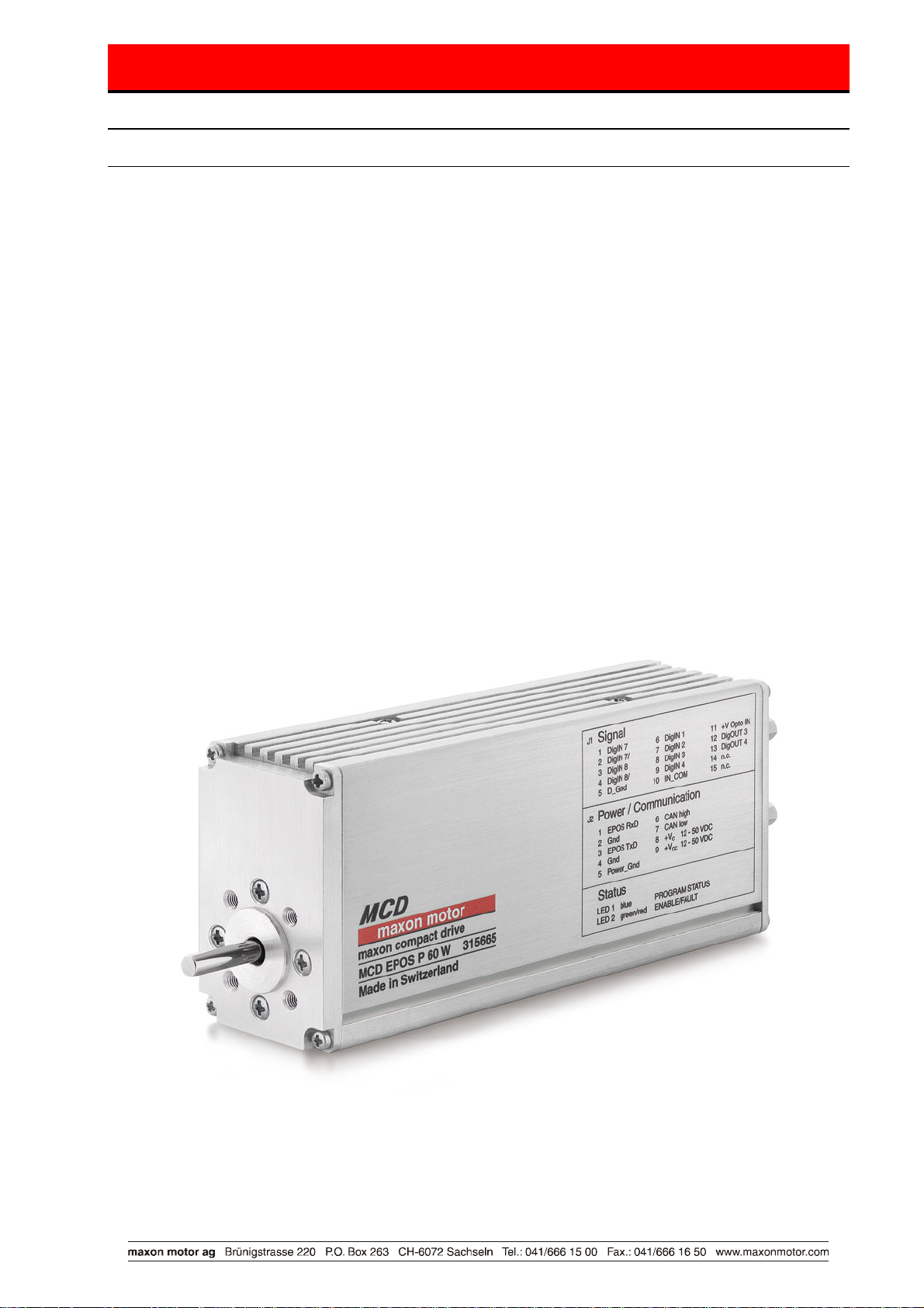
The maxon MCD EPOS P 60 W is a small-sized free
programmable compact drive. It contains a brushless EC motor
with Hall-sensors, digital Encoder and a digital position control
unit. The optimized commutation by space vector control offers to
drive the integrated brushless EC motor with minimal torque
ripple and low noise. The integrated position-, velocity- and
current control functionality allows sophisticated positioning
applications. The MCD EPOS P 60 W is programmable with a
very efficient software tool. The programming languages are
according to IEC 61131-3 standard. The built-in CANopen
interface allows the design of an easy-to-use standalone multiple
axis system, particularly with standard maxon MCD EPOS controllers or standard maxon EPOS
controllers. In addition the unit can be operated through any RS-232 communication port.
The latest edition of these “Hardware Reference”, additional documentation and software to the MCD
EPOS compact drive may also be found on the internet under
<Service & Downloads> or in the maxon motor e-shop http://shop.maxonmotor.com.
Figure 1: MCD EPOS P 60 W
http://www.maxonmotor.com category
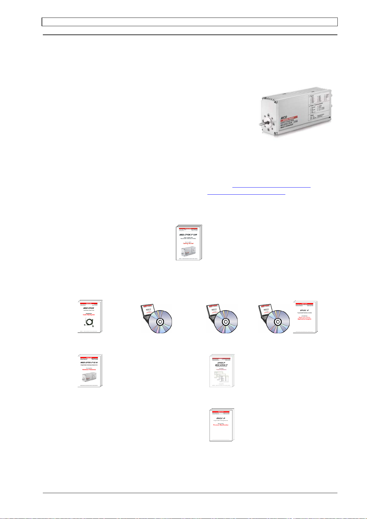
4 How to use this guide
Setup
Getting Started
Installation Configuration Programming Application
Cable Starting Set
Hardware Reference
EPOS Studio
EPOS Studio
Programming
Reference
Application Notes
Application Samples
Firmware
Specification
Figure 2: EPOS documentation hierarchy
April 2009 Edition / document number 787218-04 / subject to change maxon motor control 3
maxon motor
Hardware Reference MCD EPOS P 60 W
5 Safety Instructions
Skilled Personnel
Installation and starting of the equipment shall only be performed by experienced,
skilled personnel.
Statutory Regulations
The user must ensure that the compact drive and the components belonging to it
are assembled and connected according to local statutory regulations.
Load Disconnected
For primary operation the compact drive should be free running, i.e. with the load
disconnected.
Additional Safety Equipment
Any electronic apparatus is, in principle, not fail-safe. Machines and apparatus
must therefore be fitted with independent monitoring and safety equipment. If the
equipment breaks down, if it is operated incorrectly, if the control unit breaks down
or if the cables break, etc., it must be ensured that the drive or the complete
apparatus is kept in a safe operating mode.
Repairs
Repairs may be made by authorized personnel only or by the manufacturer.
Improper repairs can result in substantial dangers for the user.
Danger
During installation of the MCD EPOS P 60 W, make sure to disconnect all
apparatus from the electrical supply.
After switch-on, do not touch any life parts!
Max. Supply Voltage
Make sure that the supply voltage is between 12 and 50 VDC. Voltages higher than
55 VDC or of wrong polarity will destroy the unit.
Electrostatic Sensitive Device (ESD)
April 2009 Edition / document number 787218-04 / subject to change maxon motor control 4

maxon motor
Hardware Reference MCD EPOS P 60 W
6 Performance Data
6.1 Motor data
Nominal torque (max. continuous torque) .............. 54 mNm (Ta=25°C, 5000 rpm)
Max. torque ................................................................................................ 218 mNm
Max. permissible speed (restricted by Encoder) ..................................... 12000 rpm
Max. efficiency .................................................................................................. 70 %
Torque constant .................................................................................... 24.3 mNm/A
Speed constant ......................................................................................... 393 rpm/V
Speed / Torque gradient .................................................................... 20.6 rpm/mNm
Rotor inertia .............................................................................................. 21.9 gcm
Axial play at axial load < 6 N ....................................................................... 0 mm
> 6 N .................................................................. 0.14 mm
Radial play ................................................................................................ preloaded
Max. axial load (dynamic) ................................................................................. 5.5 N
Max. force for press fits (static) ....................................................................... 100 N
Max. radial loading, 5 mm from flange .............................................................. 25 N
6.2 Electrical data
Power supply voltage VCC (Ripple < 10%) .......................................... 12 … 50 VDC
Logic supply voltage V
Max. output voltage ..................................................................................... 0.9 · V
Max. output current I
Continuous output current I
Switching frequency ....................................................................................... 50 kHz
Max. efficiency .................................................................................................. 93 %
Sample rate PI - current controller ................................................................. 10 kHz
Sample rate PI - speed controller .................................................................... 1 kHz
Sample rate PID - positioning controller .......................................................... 1 kHz
Position resolution ............................................................................................ 0.09°
Position accuracy...................................................................................... typical ± 1°
Position reproducibility......................................................................... typical ± 0.09°
Hall sensor signals ................................. Hall sensor 1, Hall sensor 2, Hall sensor 3
Encoder signals .............................................................................. 1000 Increments
A, A\, B, B\, I, I\ (max. 200 KHz)
(Ripple < 10%) (optional) ............................. 12 … 50 VDC
C
....................................................................................... 9 A
max
...................................... 2.6 A (Ta=25°C, 5000 rpm)
cont
1)
2
CC
1)
6.3 Inputs
Digital input 1 (“General Purpose”) ............. opto-isolated ................ +9 ... +24 VDC
Digital input 2 (“Home Switch”) ................... opto-isolated ................ +9 ... +24 VDC
Digital input 3 (“Positive Limit Switch”) ....... opto-isolated ................ +9 ... +24 VDC
Digital input 4 (“Negative Limit Switch”) ...... opto-isolated ................ +9 ... +24 VDC
Digital input 7 (“High Speed Command”) ............ line receiver EIA standard RS-422
Digital input 8 (“High Speed Command”) ............ line receiver EIA standard RS-422
+V Opto IN ...................................................................................... +12 … +24 VDC
6.4 Outputs
Digital output 3 (“General Purpose”) ...... opto-isolated max. 24 VDC (IL < 350 mA)
Digital output 4 (“General Purpose”) ...... opto-isolated max. 24 VDC (I
1)
Valid at Ta =25°C, thermally isolated, no convection and 5000 rpm
Higher value (I
max.3A) possible with better ambient conditions for example:
cont
- free convection or forced air cooling
- thermal coupling
- lower speed
April 2009 Edition / document number 787218-04 / subject to change maxon motor control 5
< 350 mA)
L

maxon motor
Hardware Reference MCD EPOS P 60 W
6.5 Interfaces
RS-232 .............................. RxD; TxD ......................................... max. 115 200 bit/s
CAN (high speed) ............. CAN_H (high); CAN_L (low) .................... max.1 MBit/s
CAN-ID, no mechanical switch, configured according to ............ LSS CiA DSP-305
6.6 Memory Data
Total memory.............................................................................................. 512 kByte
Application memory (free programmable) ......................................... 256 kByte
Non-volatile memory ............................................................................ 512 Byte
6.7 LED indicator
Bi-colour LED .......................................................... green = ENABLE, red = FAULT
Blue LED .................................................................................. PROGRAM STATUS
6.8 Ambient temperature- / Humidity range
Protection class ......................................................................... IP42 (optional IP54)
Operating .............................................................................................. -20 ... +85°C
................................................................... power derating 1.4%/K above T
a
Storage ................................................................................................. -40 ... +85°C
Non condensating .................................................................................... 20 ... 80 %
Max. case temperature ................................................................................ < 100°C
=25°C
1)
6.9 Mechanical data
Weight ................................................................................................. approx. 495 g
Dimensions (L x W x H) ................................................................ 120 x 33 x 53 mm
Mounting plate ............................................................................. for M3x4.5 screws
6.10 Connections
J1 Signal ...................................... D-Sub connector High-Density 15 poles (female)
J2 Power / Communication .................................... D-Sub connector 9 poles (male)
6.11 Order number
MCD EPOS P 60 W ...................................................................................... 315665
Suitable plug: ............................................... D-Sub connector High-Density 15 poles (male)
Suitable plug: .................................................................... D-Sub connector 9 poles (female)
1)
Valid at Ta =25°C, thermally isolated, no convection and 5000 rpm
Higher value (I
max.3A) possible with better ambient conditions for example:
cont
- free convection or forced air cooling
- thermal coupling
- lower speed
April 2009 Edition / document number 787218-04 / subject to change maxon motor control 6
 Loading...