

Page 1

maxon motor ag Brünigstrasse 220 P.O.Box 263 CH-6072 Sachseln Phone +41 41 666 15 00 Fax +41 41 666 16 50 www.maxonmotor.com
Edition December 2017
EPOS4 Positioning Controller
Hardware Reference
maxon motor control
Extension Card
P/N 581245
Hardware Reference
Document ID: rel7777
Page 2

maxon motor control
A-2 Document ID: rel7777 EPOS4 Positioning Controller
Edition: December 2017 EPOS4 EtherCAT Card Hardware Reference
© 2017 maxon motor. Subject to change without prior notice.
1 About 3
1.1 About this Document . . . . . . . . . . . . . . . . . . . . . . . . . . . . . . . . . . . . . . . . . . . . 3
1.2 About the Device . . . . . . . . . . . . . . . . . . . . . . . . . . . . . . . . . . . . . . . . . . . . . . . 5
1.3 About the Safety Precautions. . . . . . . . . . . . . . . . . . . . . . . . . . . . . . . . . . . . . . 6
2 Specifications 7
2.1 Technical Data . . . . . . . . . . . . . . . . . . . . . . . . . . . . . . . . . . . . . . . . . . . . . . . . . 7
2.2 Dimensional Drawings . . . . . . . . . . . . . . . . . . . . . . . . . . . . . . . . . . . . . . . . . . . 8
2.3 Standards . . . . . . . . . . . . . . . . . . . . . . . . . . . . . . . . . . . . . . . . . . . . . . . . . . . . . 9
3Setup 11
3.1 Generally applicable Rules. . . . . . . . . . . . . . . . . . . . . . . . . . . . . . . . . . . . . . . 11
3.2 Connections . . . . . . . . . . . . . . . . . . . . . . . . . . . . . . . . . . . . . . . . . . . . . . . . . . 11
3.3 Installation . . . . . . . . . . . . . . . . . . . . . . . . . . . . . . . . . . . . . . . . . . . . . . . . . . . 13
3.3.1 EPOS4 Controllers with encased Housing . . . . . . . . . . . . . . . . . . . . . . . . . . . . . . . . . . 13
3.3.2 EPOS4 Modules . . . . . . . . . . . . . . . . . . . . . . . . . . . . . . . . . . . . . . . . . . . . . . . . . . . . . . 15
4 Motherboard Design Guide 17
4.1 Schematic Overview. . . . . . . . . . . . . . . . . . . . . . . . . . . . . . . . . . . . . . . . . . . . 17
4.2 Requirements for Components of Third-party Suppliers . . . . . . . . . . . . . . . . 18
4.2.1 Card Edge Connector & Socket Headers . . . . . . . . . . . . . . . . . . . . . . . . . . . . . . . . . . . 18
4.2.2 Supply Voltage. . . . . . . . . . . . . . . . . . . . . . . . . . . . . . . . . . . . . . . . . . . . . . . . . . . . . . . . 18
4.2.3 EtherCAT Status LEDs . . . . . . . . . . . . . . . . . . . . . . . . . . . . . . . . . . . . . . . . . . . . . . . . . 19
4.2.4 EtherCAT Port LEDs . . . . . . . . . . . . . . . . . . . . . . . . . . . . . . . . . . . . . . . . . . . . . . . . . . . 20
4.2.5 EtherCAT Connectors . . . . . . . . . . . . . . . . . . . . . . . . . . . . . . . . . . . . . . . . . . . . . . . . . . 21
4.2.6 Recommended Components and Manufacturers . . . . . . . . . . . . . . . . . . . . . . . . . . . . . 23
4.3 THT Footprint . . . . . . . . . . . . . . . . . . . . . . . . . . . . . . . . . . . . . . . . . . . . . . . . . 24
TABLE OF CONTENTS
READ THIS FIRST
These instructions are intended for qualified technical personnel. Prior commencing with any activities…
• you must carefully read and understand this manual and
• you must follow the instructions given therein.
Page 3
About
About this Document
maxon motor control
EPOS4 Positioning Controller Document ID: rel7777
1-3
EPOS4 EtherCAT Card Hardware Reference Edition: December 2017
© 2017 maxon motor. Subject to change without prior notice.
1 About
1.1 About this Document
1.1.1 Intended Purpose
Use the document
to…
–stay safe,
–be fast,
–end up with set
up and ready-to-go
equipment.
The purpose of the present document is to familiarize you with the EPOS4 EtherCAT Card. It will highlight the tasks for safe and adequate installation and/or commissioning. Follow the described instructions …
• to avoid dangerous situations,
• to keep installation and/or commissioning time at a minimum,
• to increase reliability and service life of the described equipment.
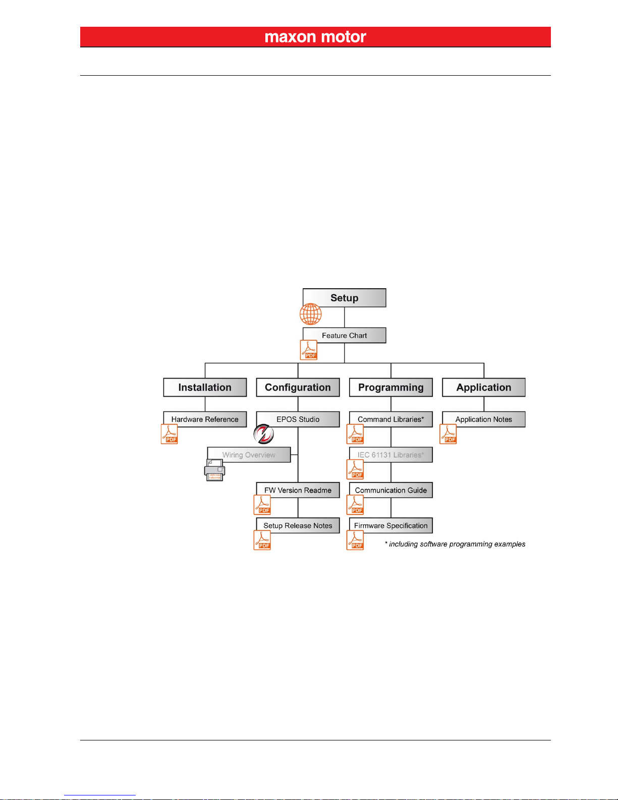
The present document is part of a documentation set and contains performance data and specifications,
information on fulfilled standards, details on connections and pin assignment, and wiring examples. The
below overview shows the documentation hierarchy and the interrelationship of its individual parts:
Figure 1-1 Documentation structure
1.1.2 Target Audience
The present document is intended for trained and skilled personnel. It conveys information on how to
understand and fulfill the respective work and duties.
Page 4
About
About this Document
maxon motor control
1-4 Document ID: rel7777 EPOS4 Positioning Controller
Edition: December 2017 EPOS4 EtherCAT Card Hardware Reference
© 2017 maxon motor. Subject to change without prior notice.
1.1.3 How to use
Throughout the document, the following notations and codes will be used.
Table 1-1 Notation used
1.1.4 Symbols & Signs
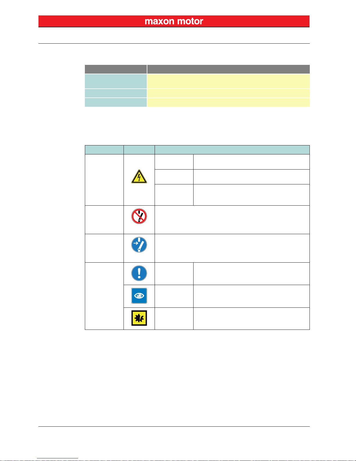
In the course of the present document, the following symbols and sings will be used.
Table 1-2 Symbols and signs
Notation Meaning
Module
refers to an EPOS4 Module (such as «EPOS4 Module 24/1.5», «EPOS4
Module 50/15»,and others)
(n) refers to an item (such as part numbers, list items, etc.)
denotes “see”, “see also”, “take note of” or “go to”
Typ e Symbol Meaning
Safety alert
(typical)
DANGER
Indicates an imminent hazardous situation. If not
avoided, it will result in death or serious injury.
WARNING
Indicates a potential hazardous situation. If not
avoided, it can result in death or serious injury.
CAUTION
Indicates a probable hazardous situation or calls
the attention to unsafe practices. If not avoided, it
may result in injury.
Prohibited
action
(typical)
Indicates a dangerous action. Hence, you must not!
Mandatory
action
(typical)
Indicates a mandatory action. Hence, you must!
Information
Requirement /
Note / Remark
Indicates an activity you must perform prior
continuing, or gives information on a particular item
you need to observe.
Best practice
Indicates an advice or recommendation on the
easiest and best way to further proceed.
Material
Damage
Indicates information particular to possible damage
of the equipment.
Page 5
About
About the Device
maxon motor control
EPOS4 Positioning Controller Document ID: rel7777
1-5
EPOS4 EtherCAT Card Hardware Reference Edition: December 2017
© 2017 maxon motor. Subject to change without prior notice.
1.1.5 Trademarks and Brand Names
For easier legibility, registered brand names are listed below and will not be further tagged with their
respective trademark. It must be understood that the brands (the list below is not necessarily concluding) are protected by copyright and/or other intellectual property rights even if their legal trademarks are
omitted in the later course of this document.
Table 1-3 Brand names and trademark owners
1.1.6 Copyright
© 2017 maxon motor. All rights reserved.
The present document – including all parts thereof – is protected by copyright. Any use (including reproduction, translation, microfilming, and other means of electronic data processing) beyond the narrow
restrictions of the copyright law without the prior approval of maxon motor ag, is not permitted and subject to prosecution under the applicable law.
1.2 About the Device
Capabilities of the
device, included features, and supported
controllers.
maxon motor control's «EPOS4 EtherCAT Card» is a plug-in extension card to provide complete EtherCAT communication capability for an EPOS4 positioning controller. It is optionally available to equip
either an EPOS4 encased housing variant or an EPOS4 Module with full EtherCAT functionality. For the
latter, development of an own motherboard as to particular guidelines is needed (for details chapter “4
Motherboard Design Guide” on page 4-17).
Find the latest edition of the present document as well as additional documentation and software for
EPOS4 positioning controllers also on the Internet: http://epos.maxonmotor.com
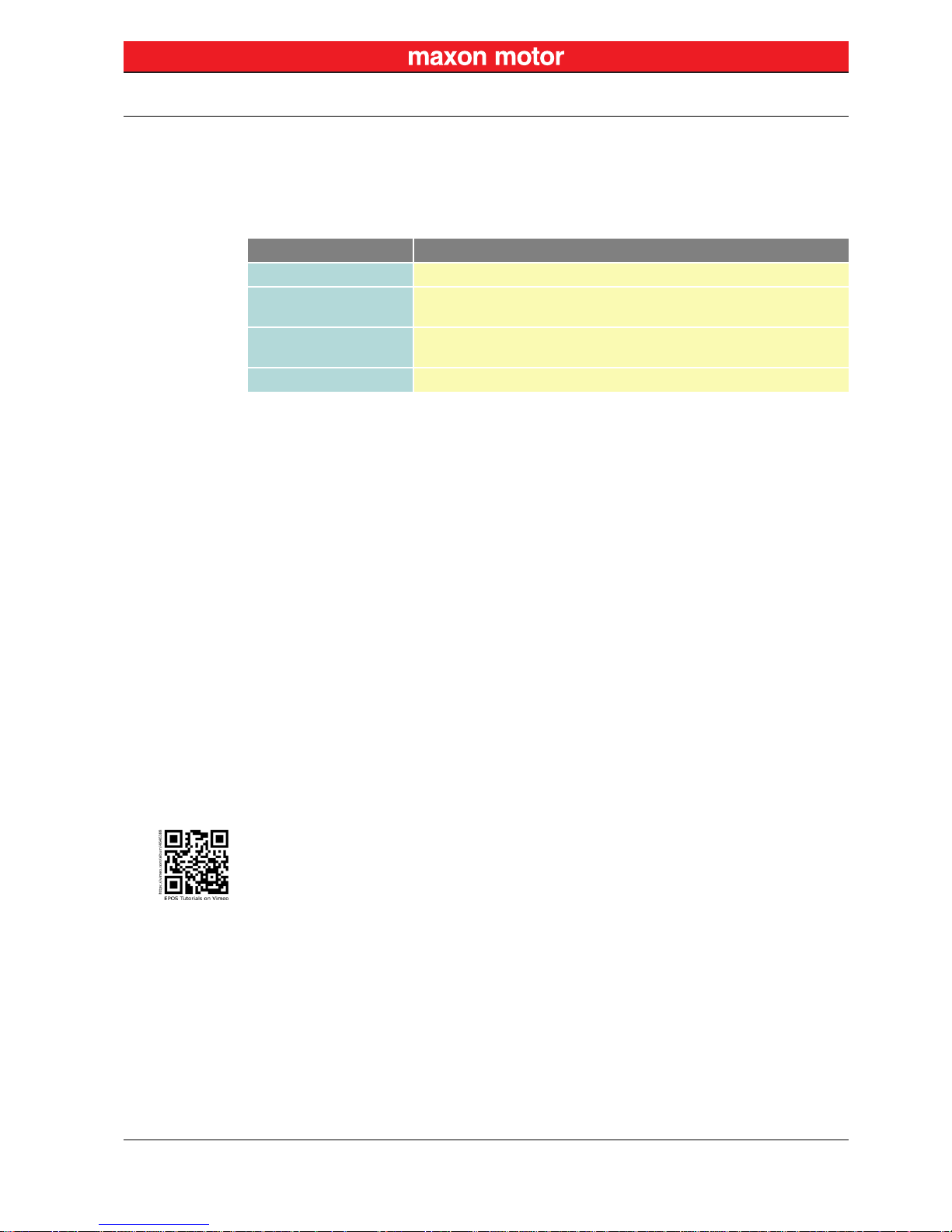
In addition, you may wish to browse the EPOS video library. It features video tutorials that provide easy
to follow instructions on how to get started with «EPOS Studio» and shows you tips and tricks on how to
setup communication interfaces, and so on. Explore on Vimeo: https://vimeo.com/album/4646388
Brand Name Trademark Owner
Adobe® Reader® © Adobe Systems Incorporated, USA-San Jose, CA
EtherCAT®
© EtherCAT Technology Group, DE-Nuremberg, licensed by Beckhoff
Automation GmbH, DE-Verl
PCI Express®
PCIe®
© PCI-SIG, USA-Beaverton, OR
Windows® © Microsoft Corporation, USA-Redmond, WA
maxon motor ag
Brünigstrasse 220
P.O.Box 263
CH-6072 Sachseln
Phone
Fax
Web
+41 41 666 15 00
+41 41 666 16 50
www.maxonmotor.com
Page 6
About
About the Safety Precautions
maxon motor control
1-6 Document ID: rel7777 EPOS4 Positioning Controller
Edition: December 2017 EPOS4 EtherCAT Card Hardware Reference
© 2017 maxon motor. Subject to change without prior notice.
1.3 About the Safety Precautions
Keep in mind:
Safety first! Always!
• Make sure that you have read and understood the note “READ THIS FIRST” on page A-2!
• Do not engage with any work unless you possess the stated skills (chapter “1.1.2 Target
Audience” on page 1-3)!
• Refer to chapter “1.1.4 Symbols & Signs” on page 1-4 to understand the subsequently used
indicators!
• You must observe any regulation applicable in the country and/or at the site of implementation
with regard to health and safety/accident prevention and/or environmental protection!
Requirements
• Make sure that all associated devices and components are installed according to local regulations.
• Be aware that, by principle, an electronic apparatus cannot be considered fail-safe. There fo re, you
must make sure that any machine/apparatus has been fitted with independent monitoring and safety
equipment. If the machine/ apparat us shoul d break down, if it is operated incorrectly, if the control unit
breaks down or if the cables break or get disconnected, etc., the complete drive system must return –
and be kept – in a safe operating mode.
• Be aware that you are not entitled to perform any repair on components supplied by maxon motor.
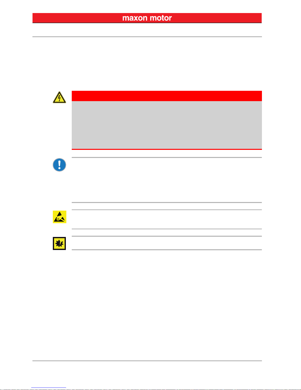
Electrostatic sensitive device (ESD)
• Wear working cloth and use equipment in compliance with ESD protective measures.
• Handle device with extra care.
Hot plugging/hot swapping the card may cause hardware damage
Switch off the controller’s power supply before removing or inserting an extension card.
DANGER
High voltage and/or electrical shock
Touching live wires causes death or serious injuries!
• Consider any power cable as connected to live power, unless having proven the opposite!
• Make sure that neither end of cable is connected to live power!
• Make sure that power source cannot be engaged while work is in process!
• Obey lock-out/tag-out procedures!
• Make sure to securely lock any power engaging equipment against unintentional engagement and
tag it with your name!
Page 7
Specifications
Technical Data
maxon motor control
EPOS4 Positioning Controller Document ID: rel7777
2-7
EPOS4 EtherCAT Card Hardware Reference Edition: December 2017
© 2017 maxon motor. Subject to change without prior notice.
2 Specifications
2.1 Technical Data
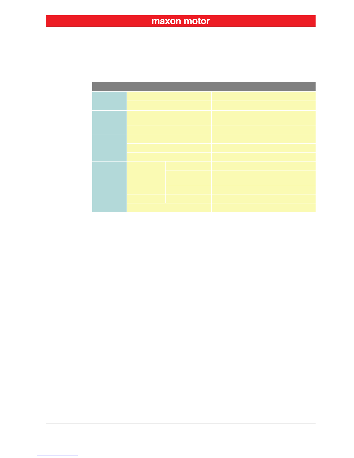
Table 2-4 Technical data
EPOS4 EtherCAT Card (581245)
Electrical
Rating
Nominal power supply voltage +V
CC
10…70 VDC
Absolute supply voltage +V
min
/ +V
max
8 VDC / 76 VDC
Interface
EtherCAT input
EtherCAT output
As to IEEE 802.3 100 Base T
Max. bit rate 100 Mbit/s (full duplex)
Physical
Weight approx. 7 g
Dimensions (L x W x H) 41 x 25 x 9.2 mm
Mounting Card edge connector, PCIe; 2x18 position
Environ-
mental
Conditions
Temperature
Operation −30…+60 °C
Extended range 1)
For details consult Hardware Reference of
respective EPOS4 controller
Storage −40…+85 °C
Altitude 2) Operation 0…10’000 m MSL
Humidity 5…90% (condensation not permitted)
Legend
1) Operation within the extended range is permitted. However, a respective derating (declination
of output current I
cont
) as to the stated values will apply.
2) Operating altitude in meters above Mean Sea Level, MSL.
Page 8
Specifications
Dimensional Drawings
maxon motor control
2-8 Document ID: rel7777 EPOS4 Positioning Controller
Edition: December 2017 EPOS4 EtherCAT Card Hardware Reference
© 2017 maxon motor. Subject to change without prior notice.
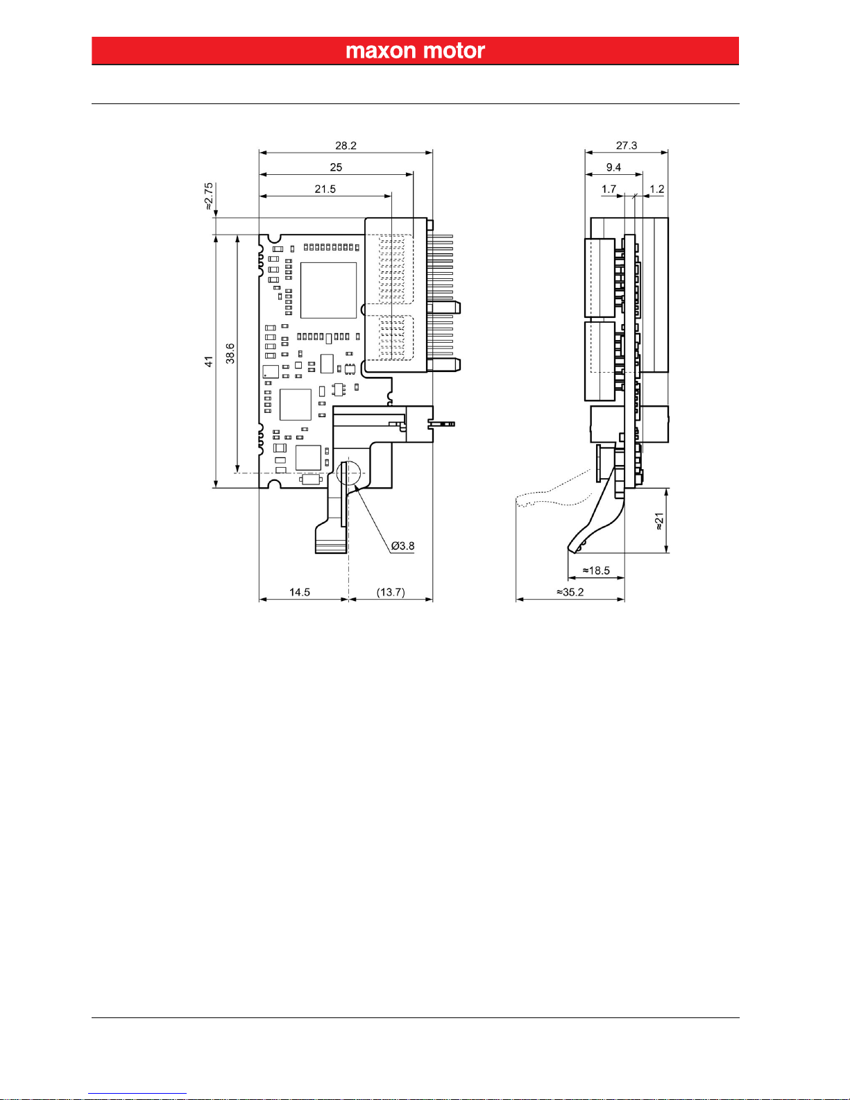
2.2 Dimensional Drawings
Figure 2-2 EPOS4 EtherCAT Card with card edge connector & retainer – Dimensional drawing [mm]
Page 9
Specifications
Standards
maxon motor control
EPOS4 Positioning Controller Document ID: rel7777
2-9
EPOS4 EtherCAT Card Hardware Reference Edition: December 2017
© 2017 maxon motor. Subject to change without prior notice.
2.3 Standards
The described device has been successfully tested for compliance with the below listed standards. In
practical terms, only the complete system (the fully operational equipment comprising all individual components, such as motor, servo controller, power supply unit, EMC filter, cabling etc.) can undergo an
EMC test to ensure interference-free operation.
Important notice
The device’s compliance with the mentioned standards does not imply its compliance within the final,
ready to operate setup. In order to achieve compliance of your operational system, you must perform
EMC testing of the involved equipment as a whole.
Table 2-5 Standards
Electromagnetic Compatibility
Generic
IEC/EN 61000-6-2 Immunity for industrial environments
IEC/EN 61000-6-3
Emission standard for residential, commercial and lightindustrial environments
Applied
IEC/EN 55022
(CISPR22)
Radio disturbance characteristics / radio interference
IEC/EN 61000-4-3
Radiated, radio-frequency, electromagnetic field immunity test
>10 V/m
IEC/EN 61000-4-4 Electrical fast transient/burst immunity test ±2 kV
IEC/EN 61000-4-6
Immunity to conducted disturbances, induced by radiofrequency fields 10 Vrms
Others
Environment
IEC/EN 60068-2-6
Environmental testing – Test Fc: Vibration (sinusoidal,
10…500 Hz, 20 m/s
2
)
MIL-STD-810F
Random transport (10…500 Hz up to 2.53 g
rms
)
Safety UL File Number Unassembled printed circuit board: E207844
Reliability MIL-HDBK-217F
Reliability prediction of electronic equipment
Environment: Ground, benign (GB)
Ambient temperature: 298 K (25 °C)
Component stress: In accordance with circuit diagram and
nominal power
Mean Time Between Failures (MTBF) 544’021 hours
Page 10

Specifications
Standards
maxon motor control
2-10 Document ID: rel7777 EPOS4 Positioning Controller
Edition: December 2017 EPOS4 EtherCAT Card Hardware Reference
© 2017 maxon motor. Subject to change without prior notice.
••page intentionally left blank••
Page 11

Setup
Generally applicable Rules
maxon motor control
EPOS4 Positioning Controller Document ID: rel7777
3-11
EPOS4 EtherCAT Card Hardware Reference Edition: December 2017
© 2017 maxon motor. Subject to change without prior notice.
3Setup
3.1 Generally applicable Rules
Maximal permitted supply voltage
• Make sure that supply power is between 10…70 VDC.
• Supply voltages above 76 VDC, or wrong polarity will destroy the unit.
Hot plugging/hot swapping the card may cause hardware damage
Switch off the controller’s power supply before removing or inserting an extension card.
3.2 Connections
Figure 3-3 EPOS4 EtherCAT Card – PCB with connector arrays
Page 12

Setup
Connections
maxon motor control
3-12 Document ID: rel7777 EPOS4 Positioning Controller
Edition: December 2017 EPOS4 EtherCAT Card Hardware Reference
© 2017 maxon motor. Subject to change without prior notice.
Table 3-6 Connector arrays – Pin assignment
Array
A
Array
B
Pin Signal Description Pin Signal Description
A1 –
Connect to
EtherCAT OUT X15 | 4
B1 TX+_OUT
EtherCAT OUT
Transmission Data+
A2 –
Connect to
EtherCAT OUT X15 | 5
B2 TX−_OUT
EtherCAT OUT
Transmission Data−
A3 –
Connect to
EtherCAT OUT X15 | 7
B3 RX+_OUT
EtherCAT OUT
Receive Data+
A4 –
Connect to
EtherCAT OUT X15 | 8
B4 RX−_OUT
EtherCAT OUT
Receive Data−
A5 –
Connect to
EtherCAT IN X14 | 4
B5 TX+_IN
EtherCAT IN
Transmission Data+
A6 –
Connect to
EtherCAT IN X14 | 5
B6 TX−_IN
EtherCAT IN
Transmission Data−
A7 –
Connect to
EtherCAT IN X14 | 7
B7 RX+_IN
EtherCAT IN
Receive Data+
A8 –
Connect to
EtherCAT IN X14 | 8
B8 RX−_IN
EtherCAT IN
Receive Data−
A9 LED_EtherCAT_OUT
Link activity of port
EtherCAT OUT X15
B9 LED_EtherCAT_IN
Link activity of port
EtherCAT IN X14
A10 – not connected B10 – not connected
A11 LED_Status_red EtherCAT status “Error” B11 LED_Status_green EtherCAT status “Run”
A12 Shield Cable shield B12 SPI_SOMI
SPI Slave output/Master
input
A13 GND Ground B13 SPI_SIMO
SPI Slave input/Master
output
A14 GND Ground B14 SPI_CLK SPI clock
A15 – not connected B15 SPI_CS2 SPI chip select 2
A16 – not connected B16 SPI_IRQ SPI interrupt request
A17 GND Ground B17 – not connected
A18
+V
CC
Nominal power supply
voltage (+10…+70 VDC)
B18 – not connected
Page 13

Setup
Installation
maxon motor control
EPOS4 Positioning Controller Document ID: rel7777
3-13
EPOS4 EtherCAT Card Hardware Reference Edition: December 2017
© 2017 maxon motor. Subject to change without prior notice.
3.3 Installation
The procedure varies depending on the type of controller you are using:
• EPOS4 controllers with encased housing feature two ready-to-use extension slots.
• EPOS4 Modules require a custom-made motherboard (for details on design and layout
chapter “4 Motherboard Design Guide” on page 4-17) with a PCIe card edge connector.
Hot plugging/hot swapping the card may cause hardware damage
Switch off the controller’s power supply before removing or inserting an extension card.
Electrostatic sensitive device (ESD)
• Wear working cloth and use equipment in compliance with ESD protective measures.
• Handle device with extra care.
3.3.1 EPOS4 Controllers with encased Housing
The controllers provide two extension slots (EXT1 & EXT2) located underneath the plastic lid at the
housing’s top face (Figure 3-4). The plastic lid will mechanically interlock the inserted extension card
in both horizontal and vertical direction.
• EXT1 hosts the «EPOS4 EtherCAT Card».
• EXT2 provides connectivity for advanced signal extension cards, such as for additional abso-
lute sensors or customized signal extensions.
Figure 3-4 Extension slots – as an example «EPOS4 50/5»
Continued on next page.
Page 14

Setup
Installation
maxon motor control
3-14 Document ID: rel7777 EPOS4 Positioning Controller
Edition: December 2017 EPOS4 EtherCAT Card Hardware Reference
© 2017 maxon motor. Subject to change without prior notice.
Figure 3-5 EPOS4 EtherCAT Card – Installation & removal
Switch off the controller’s power supply.
Comply with ESD protective measures.
Open plastic lid
1) Unlock the two latches (A) on the plastic lid.
2) Lift the plastic lid upward (B) and
remove.
Remove extension card, if necessary
3) Turn the plastic lid over and look for
the molded catch in one of its corners.
4) Insert the catch into the extension
card’s bore (C).
5) Pull both – the plastic lid together with
the extension card – straight upward
(D).
Make sure that the extension slots are
clean and free of any foreign objects.
Insert extension card
6) Align the extension card with the PCIe
card edge connector and keep it rightangled (E).
7) Carefully insert the extension card in
the extension slot EXT1 while keeping
it right-angled and press down all the
way into the PCIe card edge connector
(F).
Close plastic lid
8) Engage the plastic lid at its rear edge
(G).
9) Fold down the plastic lid (H), press it
down firmly, and let the two latches
snap into place.
Page 15

Setup
Installation
maxon motor control
EPOS4 Positioning Controller Document ID: rel7777
3-15
EPOS4 EtherCAT Card Hardware Reference Edition: December 2017
© 2017 maxon motor. Subject to change without prior notice.
3.3.2 EPOS4 Modules
The connection of the «EPOS4 EtherCAT Card» can be established via a custom-made motherboard
which defines the actual installation procedure.
Depending on the case of application (with possibly involved strong movements and high dynamic
accelerations) and to guarantee failsafe operation, you might wish to consider the use of a PCIe card
edge connector with retainer (Figure 3-6). The retainer will mechanically interlock the inserted extension card in both horizontal and vertical direction.
Figure 3-6 EPOS4 EtherCAT Card with PCIe card edge connector and retainer
Page 16

Setup
Installation
maxon motor control
3-16 Document ID: rel7777 EPOS4 Positioning Controller
Edition: December 2017 EPOS4 EtherCAT Card Hardware Reference
© 2017 maxon motor. Subject to change without prior notice.
••page intentionally left blank••
Page 17

Motherboard Design Guide
Schematic Overview
maxon motor control
EPOS4 Positioning Controller Document ID: rel7777
4-17
EPOS4 EtherCAT Card Hardware Reference Edition: December 2017
© 2017 maxon motor. Subject to change without prior notice.
4 Motherboard Design Guide
The «Motherboard Design Guide» provides helpful information on integrating the EPOS4 EtherCAT
Card on a printed circuit board. It contains recommendations for the motherboard layout and specifies
external components that may be required, pin assignments, and connection examples.
Get help
If you are not trained in the design and development of printed circuit boards, you will need additional
support for this point.
maxon motor will be happy to provide you with a quote for designing and manufacturing a motherboard
for your specific application.
4.1 Schematic Overview
Figure 4-7 Schematic overview
CAUTION
Dangerous action
Errors in implementing the design can result in serious Injury!
• Only proceed if you are skilled in electronics design!
• Designing a printed circuit board requires special skills and knowledge and may only be performed
by experienced electronic developers!
• This quick guide is only intended as an aid, does not make any claim to completeness, and will not
automatically result in a functional component!
Page 18

Motherboard Design Guide
Requirements for Components of Third-party Suppliers
maxon motor control
4-18 Document ID: rel7777 EPOS4 Positioning Controller
Edition: December 2017 EPOS4 EtherCAT Card Hardware Reference
© 2017 maxon motor. Subject to change without prior notice.
4.2 Requirements for Components of Third-party Suppliers
Best practice
For references and recommended components consult Table 4-11.
4.2.1 Card Edge Connector & Socket Headers
For implementation of the «EPOS4 EtherCAT Card», a PCIe 2x18 position connector is required.
EPOS4 modules are available with two different types of socket headers.
• EPOS4 Module 24/1.5 (536630) and EPOS4 Module 50/5 (534130) feature 1.27 mm box
headers.
• EPOS4 Module 50/8 (504384) and EPOS4 Module 50/15 (504383) have pin headers that per-
mit two ways of mounting. They can either be plugged in a socket header or be directly soldered to a printed circuit board.
Find further details on the hardware in the separate document «Hardware Reference» of th e respective EPOS4 Module.
4.2.2 Supply Voltage
For voltage supply of the «EPOS4 EtherCAT Card», you may employ the EPOS4 Module’s power supply. For details separate document «Hardware Reference» of the respective EPOS4 Module.
If you intend to use another source as power supply, we recommend to connect a TVS (transient voltage
suppressor) diode (D1) to the voltage supply line to protect against overvoltage resulting from voltage
transients or brake energy feedback.
Page 19

Motherboard Design Guide
Requirements for Components of Third-party Suppliers
maxon motor control
EPOS4 Positioning Controller Document ID: rel7777
4-19
EPOS4 EtherCAT Card Hardware Reference Edition: December 2017
© 2017 maxon motor. Subject to change without prior notice.
4.2.3 EtherCAT Status LEDs
The «EPOS4 EtherCAT Card» provides two outputs to display the actual status and possible errors of
the EtherCAT network with LEDs (D2):
• Green LED shows the RUN state
• Red LED indicates errors
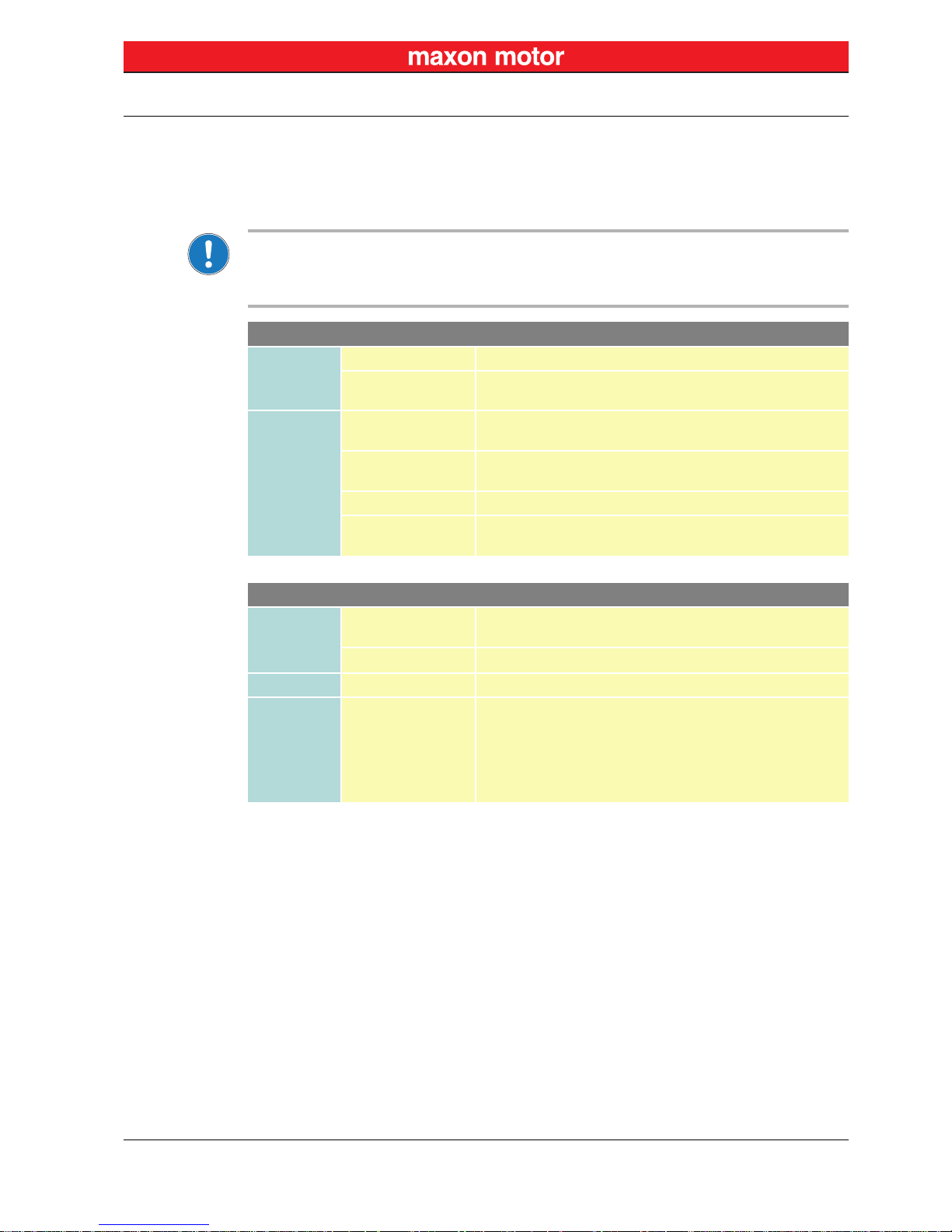
Table 4-7 EtherCAT status LEDs
The outputs are designed as open-collector circuit with internal series resistor of 150 Ohm. An external
LED can be mounted as long as the current is limited to less than 20 mA with an matching series resistor (Rs).
Figure 4-8 EtherCAT status LED “sinks” (analogously valid for B11)
LED
Description
Green Red
OFF — EPOS4 is in state INIT
Blink — EPOS4 is in state PRE-OPERATIONAL
Single flash — EPOS4 is in state SAFE-OPERATIONAL
ON — EPOS4 is in state OPERATIONAL
— OFF EPOS4 is in operating condition
— Double flash
An application watchdog timeout has occurred
Example: Timeout of Sync Manager Watchdog
— Single flash
EPOS4 has changed the COM state due to an internal error
Example: Change of state “Op” to “SafeOpError” due to Sync Error
—Blink
General Configuration Error
Example: State change commanded by master is not possible due to
actual settings (register, object, hardware configuration)
Blink = continuous blinking (≈2.5 Hz) Flash = Flashing (≈0.2 s), followed by pause of 1 s
Red/green EtherCAT status LED “sinks”
Max. input voltage +30 VDC
Max. load current 20 mA
Page 20

Motherboard Design Guide
Requirements for Components of Third-party Suppliers
maxon motor control
4-20 Document ID: rel7777 EPOS4 Positioning Controller
Edition: December 2017 EPOS4 EtherCAT Card Hardware Reference
© 2017 maxon motor. Subject to change without prior notice.
4.2.4 EtherCAT Port LEDs
The «EPOS4 EtherCAT Card» provides two outputs to display the EtherCAT port’s link activity (applies
for both ports, X14 “EtherCAT IN” and X15 “EtherCAT OUT”):
• Green LED indicates link activity
Table 4-8 EtherCAT port LEDs
The outputs are designed to drive integrated LEDs of standard modular port jacks according the following specification:
Figure 4-9 EtherCAT port activity LED “source”
LED
Description
Green
OFF Port is closed
Flicker Port is open / activity is present
ON Port is open
— Data rate is 100 Mbit/s
Flicker = Continuous flickering (≈10 Hz)
Green EtherCAT port activity LED “source”
Output voltage
U
Out
= 3.3 V − (I
Load
x 150 Ω)
Max. load current 10 mA
Page 21

Motherboard Design Guide
Requirements for Components of Third-party Suppliers
maxon motor control
EPOS4 Positioning Controller Document ID: rel7777
4-21
EPOS4 EtherCAT Card Hardware Reference Edition: December 2017
© 2017 maxon motor. Subject to change without prior notice.
4.2.5 EtherCAT Connectors
The «EPOS4 EtherCAT Card» provides both transmission and receive signals for input as well as output for an EtherCAT interface. Unused connections of the EtherCAT IN/OUT connectors (pins 4, 5, 7,
and 8) must be connected through to the PCIe plug-in contact.
In respect to short-term signal transmission and propagation times, sufficient short conducting paths and
isolation spacing must be provided.
Wrong plugging may cause hardware damage
Even though both sockets are prepared for identical external wiring, make sure to always connect them
as follows.
• Use only standard Cat5 cables with RJ45 plug, such as maxon’s «Ethernet Cable» (422827).
• Use EtherCAT IN as «Input».
• Use EtherCAT OUT as «Output».
For detailed information separate document «EPOS4 Communication Guide».
For detailed information separate document «EPOS4 Communication Guide».
Figure 4-10 EtherCAT connector
Table 4-9 EtherCAT connectors – Pin assignment
Continued on next page.
EtherCAT
EtherCAT Standard IEEE 802.3 100 Base Tx
Max. bit rate 100 Mbit/s (full duplex)
Pin Signal Description
1 TX+ Transmission Data+
2 TX− Transmission Data−
3 RX+ Receive Data+
4 TXCT not applicable
5 TXCT not applicable
6 RX− Receive Data−
7 RXCT not applicable
8 RXCT not applicable
Page 22

Motherboard Design Guide
Requirements for Components of Third-party Suppliers
maxon motor control
4-22 Document ID: rel7777 EPOS4 Positioning Controller
Edition: December 2017 EPOS4 EtherCAT Card Hardware Reference
© 2017 maxon motor. Subject to change without prior notice.
Table 4-10 Ethernet Cable
Ethernet Cable (422827)
Cross-section Cat. 5e SF/UTP (ISO/IEC 11801), 1:1 patch cable, green
Length 2 m
Head A RJ45 (8P8CS) EIA/TIA-568B
Head B RJ45 (8P8CS) EIA/TIA-568B
Page 23

Motherboard Design Guide
Requirements for Components of Third-party Suppliers
maxon motor control
EPOS4 Positioning Controller Document ID: rel7777
4-23
EPOS4 EtherCAT Card Hardware Reference Edition: December 2017
© 2017 maxon motor. Subject to change without prior notice.
4.2.6 Recommended Components and Manufacturers
Table 4-11 Motherboard Design Guide – Recommended components
Recommended components
Card Edge
Connector
(EXT1)
PCIe 2x18 Position, THT
• Amphenol FCI (10018784-10200TLF)
• Sullins Connector Solutions (NWE18DHHN-T911)
• TE Connectivity (7-1734774-6)
Retainer for Card
Edge Connector
(optional)
PCI express retainer
• Amphenol FCI (10042618-002LF)
EtherCAT Two Port
Modular Jack
(X14/X15)
• Amphenol (RJHSE-5381-02)
• Würth (615016137721)
TVS Diode
(D1)
• Vishay (SMBJ54A)
U
R
= 54 V, UBR = 60.0…66.3 V @ 1 mA, UC = 87.1 V @ 6.9 A
• Fairchild (SMBJ54A)
U
R
= 54 V, UBR = 60.0…66.3 V @ 1 mA, UC = 87.1 V @ 6.9 A
• Littelfuse (SMBJ54A)
U
R
= 54 V, UBR = 60.0…66.3 V @ 1 mA, UC = 87.1 V @ 6.9 A
LED
(D2)
Dual-sided SMT LED green/red
• Lite-On (LTST-S326KGJRKT)
• Dialight (597-2751-607F)
• Avago (HSMF-C144)
Decoupling
(Rp/Cp)
R/C chip combination
• Chip resistor 1 M Ω, 0.25 W, 500 V
• Chip capacitor 10 nF, 500 V
Page 24

Motherboard Design Guide
THT Footprint
maxon motor control
4-24 Document ID: rel7777 EPOS4 Positioning Controller
Edition: December 2017 EPOS4 EtherCAT Card Hardware Reference
© 2017 maxon motor. Subject to change without prior notice.
4.3 THT Footprint
Depending on your case of application and type of operation, considerable strong movements and high
dynamic accelerations may occur. If the case, you might wish to consider using a PCIe card edge connector with retainer which will then mechanically interlock the inserted extension card in both horizontal
and vertical direction.
Possible strong mechanical loads during operation may cause hardware damage
Operation involving strong movements and high dynamic accelerations can cause an unsecured extension card to shake loose. This can lead to serious damage of hardware or equipment and to complete
failure of the system. To avoid, use a PCIe card edge connector with retainer (Figure 4-11).
PCIe Card Edge Connector with Retainer
Figure 4-11 PCIe card edge connector with retainer – THT footprint [mm] – Top view
PCIe Card Edge Connector without Retainer
Figure 4-12 PCIe card edge connector – THT footprint [mm] – Top view
Page 25

maxon motor control
EPOS4 Positioning Controller Document ID: rel7777
Z-25
EPOS4 EtherCAT Card Hardware Reference Edition: December 2017
© 2017 maxon motor. Subject to change without prior notice.
Figure 1-1 Documentation structure. . . . . . . . . . . . . . . . . . . . . . . . . . . . . . . . . . . . . . . . . . . . . . . . . . . . . . . . . . . . . . . . . .3
Figure 2-2 EPOS4 EtherCAT Card with card edge connector & retainer – Dimensional drawing [mm] . . . . . . . . . . . . . .8
Figure 3-3 EPOS4 EtherCAT Card – PCB with connector arrays . . . . . . . . . . . . . . . . . . . . . . . . . . . . . . . . . . . . . . . . . .11
Figure 3-4 Extension slots – as an example «EPOS4 50/5» . . . . . . . . . . . . . . . . . . . . . . . . . . . . . . . . . . . . . . . . . . . . . .13
Figure 3-5 EPOS4 EtherCAT Card – Installation & removal . . . . . . . . . . . . . . . . . . . . . . . . . . . . . . . . . . . . . . . . . . . . . .14
Figure 3-6 EPOS4 EtherCAT Card with PCIe card edge connector and retainer . . . . . . . . . . . . . . . . . . . . . . . . . . . . . .15
Figure 4-7 Schematic overview . . . . . . . . . . . . . . . . . . . . . . . . . . . . . . . . . . . . . . . . . . . . . . . . . . . . . . . . . . . . . . . . . . . .17
Figure 4-8 EtherCAT status LED “sinks” (analogously valid for B11) . . . . . . . . . . . . . . . . . . . . . . . . . . . . . . . . . . . . . . .19
Figure 4-9 EtherCAT port activity LED “source”. . . . . . . . . . . . . . . . . . . . . . . . . . . . . . . . . . . . . . . . . . . . . . . . . . . . . . . .20
Figure 4-10 EtherCAT connector . . . . . . . . . . . . . . . . . . . . . . . . . . . . . . . . . . . . . . . . . . . . . . . . . . . . . . . . . . . . . . . . . . . .21
Figure 4-11 PCIe card edge connector with retainer – THT footprint [mm] – Top view . . . . . . . . . . . . . . . . . . . . . . . . . . .24
Figure 4-12 PCIe card edge connector – THT footprint [mm] – Top view . . . . . . . . . . . . . . . . . . . . . . . . . . . . . . . . . . . . .24
LIST OF FIGURES
Page 26

maxon motor control
Z-26 Document ID: rel7777 EPOS4Positioning Controller
Edition: December 2017 EPOS4 EtherCAT Card Hardware Reference
© 2017 maxon motor. Subject to change without prior notice.
Table 1-1 Notation used . . . . . . . . . . . . . . . . . . . . . . . . . . . . . . . . . . . . . . . . . . . . . . . . . . . . . . . . . . . . . . . . . . . . . . . . . . 4
Table 1-2 Symbols and signs . . . . . . . . . . . . . . . . . . . . . . . . . . . . . . . . . . . . . . . . . . . . . . . . . . . . . . . . . . . . . . . . . . . . . . 4
Table 1-3 Brand names and trademark owners . . . . . . . . . . . . . . . . . . . . . . . . . . . . . . . . . . . . . . . . . . . . . . . . . . . . . . . .5
Table 2-4 Technical data . . . . . . . . . . . . . . . . . . . . . . . . . . . . . . . . . . . . . . . . . . . . . . . . . . . . . . . . . . . . . . . . . . . . . . . . . 7
Table 2-5 Standards . . . . . . . . . . . . . . . . . . . . . . . . . . . . . . . . . . . . . . . . . . . . . . . . . . . . . . . . . . . . . . . . . . . . . . . . . . . . . 9
Table 3-6 Connector arrays – Pin assignment . . . . . . . . . . . . . . . . . . . . . . . . . . . . . . . . . . . . . . . . . . . . . . . . . . . . . . . .12
Table 4-7 EtherCAT status LEDs . . . . . . . . . . . . . . . . . . . . . . . . . . . . . . . . . . . . . . . . . . . . . . . . . . . . . . . . . . . . . . . . . .19
Table 4-8 EtherCAT port LEDs. . . . . . . . . . . . . . . . . . . . . . . . . . . . . . . . . . . . . . . . . . . . . . . . . . . . . . . . . . . . . . . . . . . .20
Table 4-9 EtherCAT connectors – Pin assignment . . . . . . . . . . . . . . . . . . . . . . . . . . . . . . . . . . . . . . . . . . . . . . . . . . . .21
Table 4-10 Ethernet Cable . . . . . . . . . . . . . . . . . . . . . . . . . . . . . . . . . . . . . . . . . . . . . . . . . . . . . . . . . . . . . . . . . . . . . . . . 22
Table 4-11 Motherboard Design Guide – Recommended components . . . . . . . . . . . . . . . . . . . . . . . . . . . . . . . . . . . . . .23
LIST OF TABLES
Page 27

maxon motor control
EPOS4 Positioning Controller Document ID: rel7777
Z-27
EPOS4 EtherCAT Card Hardware Reference Edition: December 2017
© 2017 maxon motor. Subject to change without prior notice.
A
alerts 4
applicable regulations
6
C
cables (prefab)
Ethernet Cable 22
connectors
EtherCAT IN
21
EtherCAT OUT
21
EXT1 13
EXT2
13
PCB connector arrays 11
PCIe card edge connector 15
country-specific regulations
6
E
ESD 6, 13
H
how to
get help in designing the motherboard
17
interpret icons (and signs) used in this document 4
I
informatory signs 4
L
LEDs
EtherCAT port activity
20
EtherCAT status
19
M
mandatory action signs 4
N
notations used 4
P
part numbers
422827 22
504383 18
504384
18
534130 18
536630 18
581245
7
performance data
7
pin assignment
12
precautions
6
prohibitive signs
4
protective measures (ESD)
6, 13
purpose
of the device
5
of the document
3
R
regulations, applicable 6
S
safety alerts 4
safety first!
6
signs used
4
standards, fulfilled
9
symbols used
4
T
technical data 7
INDEX
Page 28

maxon motor control
Z-28 Document ID: rel7777 EPOS4Positioning Controller
Edition: December 2017 EPOS4 EtherCAT Card Hardware Reference
© 2017 maxon motor. Subject to change without prior notice.
EtherCAT® is a registered trademark and patented technology, licensed by Beckhoff Automation GmbH, Germany
© 2017 maxon motor. All rights reserved.
The present document – including all parts thereof – is protected by copyright. Any use (including reproduction, translation,
microfilming, and other means of electronic data processing) beyond the narrow restrictions of the copyright law without the
prior approval of maxon motor ag, is not permitted and subject to prosecution under the applicable law.
maxon motor ag
Brünigstrasse 220
P.O.Box 263
CH-6072 Sachseln
Switzerland
Phone +41 41 666 15 00
Fax +41 41 666 16 50
www.maxonmotor.com
 Loading...