

Page 1
maxon motor
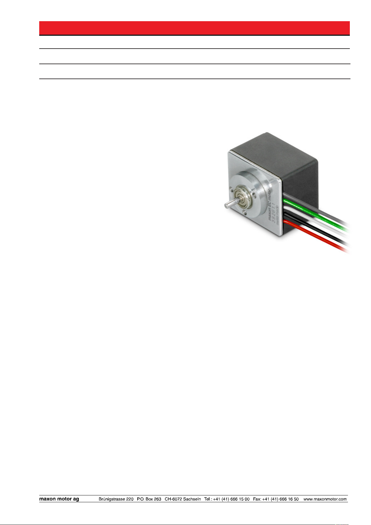
maxon EC motor EC 20 flat with integrated electronics
Doc. no. 903155
Operating Instructions Edition September 2010
Order Number: 350795, 350776, 350796, 350778, 350794, 349694, 370413, 370412, 350834, 350804,
350835, 350805, 350806, 349731, 370416, 370415
The EC 20 flat motor with integrated electronics is a brushless, speed-controlled 1-quadrant drive. The EC 20 flat
can be supplied in a 2 watt or 5 watt version.
Functions:
• Commutation with Hall sensors
• Digital speed control
• Speed range: 200 rpm – 7000 rpm (depends on version)
• Current restriction fixed
• Overvoltage and undervoltage switch-off
• Overvoltage protection
• Blockage protection, temperature monitoring
• Inverse polarity protection
2-wire version
• Speed proportional to input voltage
5-wire version
• Set value speed target through analog signal 0 ... 10 V
• 2-wire operation possible
• Versions: - «Enable» TTL level compatible
- Direction pre-selection «cw/ccw» TTL level compatible
• Speed monitor supplies frequency signal proportional to speed
Table of contents
1 Safety instructions ....................................................................................................................................... 2
2 Technical data .............................................................................................................................................. 3
3 Minimum external wiring .............................................................................................................................. 7
4 Description function of inputs and outputs 5-wire version ......................................................................... 10
5 Description function of 2-wire version ........................................................................................................ 13
6 Protective functions.................................................................................................................................... 14
7 Installation instructions .............................................................................................................................. 15
8 EMC-compliant installation ........................................................................................................................ 15
9 Trouble shooting ......................................................................................................................................... 16
10 Dimensions ................................................................................................................................................ 17
11 Glossary..................................................................................................................................................... 18
These instructions are available on the Internet as a PDF file at www.maxonmotor.com, under “Service & Downloads”. Doc. no. 903155_PDF_E.
Page 2
maxon motor
EC 20 flat with integrated electronics Operating Instructions
1 Safety instructions
Skilled personnel
Only skilled, experienced personnel should install and start the equipment.
Statutory regulations
The user must ensure that the EC 20 flat with integrated electronics and the
components belonging to it are assembled and connected according to local
statutory regulations.
Additional safety equipment
Any electronic equipment is, in principle, not fail-safe. Machinery and equipment should therefore be fitted with equipment-independent monitoring and
safety features. There must be guarantees that the drive or the entire piece of
equipment can be run safely if the equipment fails, if it is used incorrectly, if
the control unit fails, if the cable breaks etc.
Repairs
Repairs may only be carried out by authorised personnel or the manufacturer.
It is dangerous for users to open the unit or carry out any repairs.
Danger
Users must ensure that no apparatus is connected to the electrical supply
during installation of the EC 20 flat with integrated electronics! After switching
on, do not touch any live parts!
Max. supply voltage
Make sure that the supply voltage is between 10 VDC and 28 VDC. Permanently switched on voltages above 30 VDC destroy the unit.
Electrostatic sensitive components
During transportation, assembly and operation, contact of the EC 20 flat with
integrated electronics with electrostatically charged components or persons
must be avoided. The integrated electronics can be destroyed by electrostatic
discharges.
2 maxon EC motor
Temperature
The temperature of the housing, flange or components may exceed 60°C
during operation.
September 2010 Edition / document number 903155_PDF_E - 07 / subject to change
Page 3
maxon motor
Operating Instructions EC 20 flat with integrated electronics
2 Technical data
2.1 Order number
350795 (IP40), 350776 (IP00) 2-wire version, nominal speed 3000 rpm, 2 Watt
350796 (IP40), 350778 (IP00) 2-wire version, nominal speed 6000 rpm, 2 Watt
350794 (IP40), 349694 (IP00)
370413 (IP40), 370412 (IP00)
350834 (IP40), 350804 (IP00) 2-wire version, nominal speed 3000 rpm, 5 Watt
350835 (IP40), 350805 (IP00) 2-wire version, nominal speed 6000 rpm, 5 Watt
350806 (IP40), 349731 (IP00)
370416 (IP40), 370415 (IP00)
2.2 Motor data 2 Watt at 24VDC
Order number IP40 (with housing) 350795 350796 350794/370413
Order number IP00 (without housing) 350776 350778 350794/370412
Nominal voltage VDC 24 24 24
No load speed rpm 3000 6000 6000
No load current mA 14.5 19.8 19.8
Nominal speed rpm 3000 6000 6000
Nominal torque mNm 3.74 3.74 3.74
Nominal current mA 196 278 278
Max. torque mNm 5 5 5
Max. current mA 330 330 330
Max. efficiency % 25 37 37
-1
n [min
4000
3500
3000
2500
2000
1500
1000
500
]
Vcc = 28V
Vcc = 24V
Vcc = 18V
Vcc = 12V
Vcc = 10V
«Enable» 5-wire version, nominal speed 6000 rpm, 2 Watt
«cw/ccw» 5-wire version, nominal speed 6000 rpm, 2 Watt
«Enable» 5-wire version, nominal speed 6000 rpm, 5 Watt
«cw/ccw» 5-wire version, nominal speed 6000 rpm, 5 Watt
0.5 1 1.5 2 2.5 3 3.5 4 4.5 5 5.5 6
M [mNm]
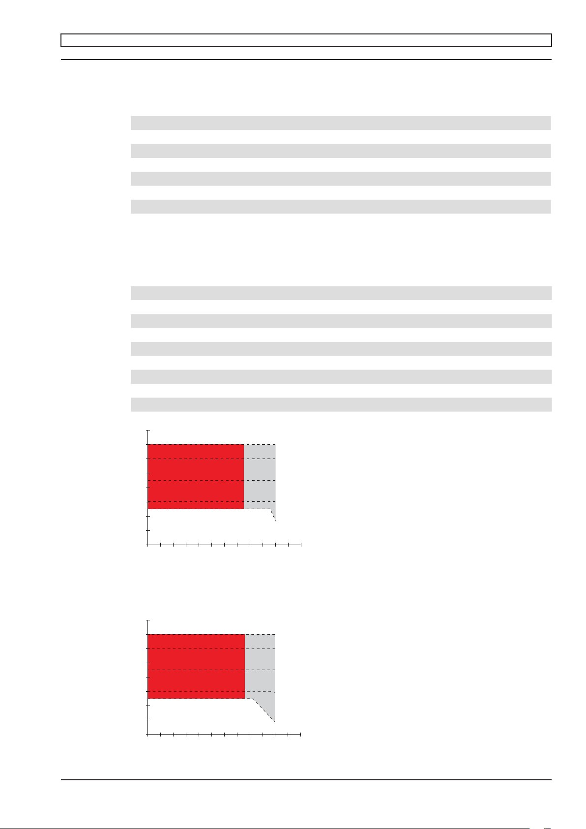
Picture 1: Operating range n = f (M)
2-wire version, nominal speed 3000 rpm, order number 350795, 350776
-1
n [min
8000
7000
6000
5000
4000
3000
2000
1000
]
Vcc = 28V
Vcc = 24V
Vcc = 18V
Vcc = 12V
Vcc = 10V
0.5 1 1.5 2 2.5 3 3.5 4 4.5 5 5.5 6
M [mNm]
Picture 2: Operating range n = f (M)
2-wire version, nominal speed 6000 rpm, order number 350796, 350778
September 2010 Edition / document number 903155_PDF_E - 07 / subject to change
maxon EC motor 3
Page 4
maxon motor
EC 20 flat with integrated electronics Operating Instructions
-1
]
n [min
7000
6000
set value = 10V
5000
4000
3000
2000
1000
set value = 5V
set value = 1V
0.5 1 1.5 2 2.5 3 3.5 4 4.5 5 5.5 6
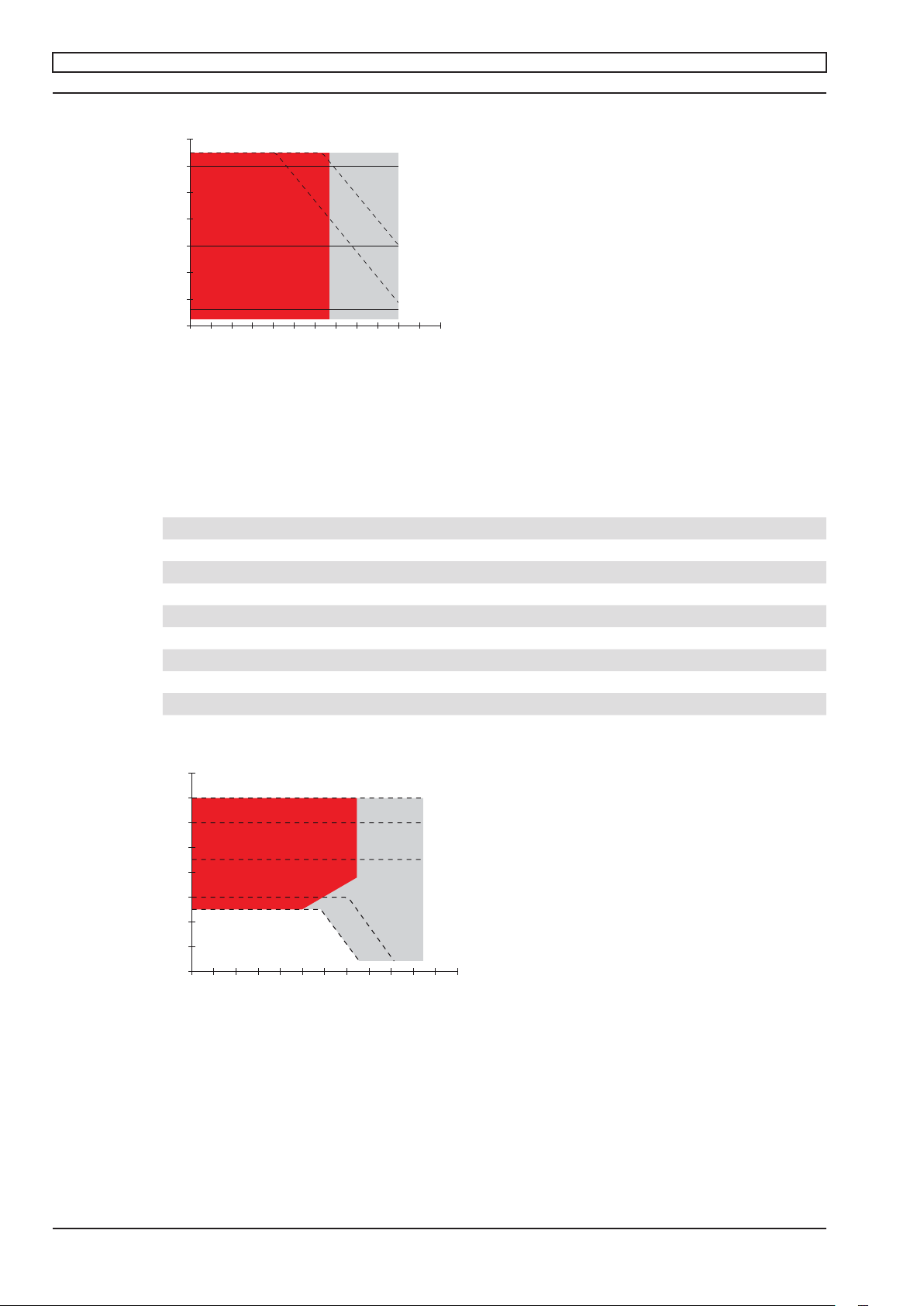
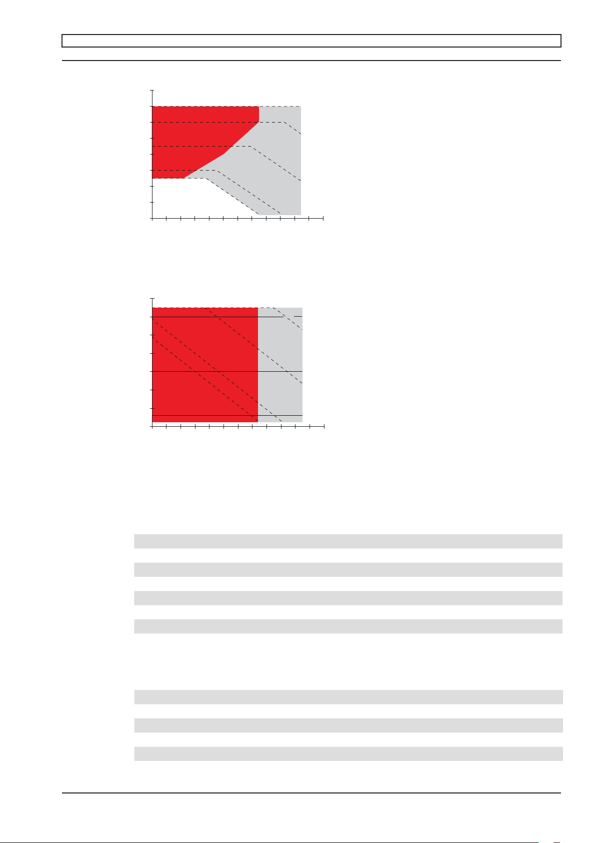
Picture 3: Operating range n = f (M)
5-wire version, order number 350794 and 349694, 370413, 370412
If the supply voltage is reduced, the torque and/or speed may change.
2.3 Motor data 5 Watt at 24VDC
Order number IP40 (with housing) 350834 350835 350806/370416
Order number IP00 (without housing) 350804 350805 349731/370415
Nominal voltage VDC 24 24 24
No load speed rpm 3000 6000 6000
No load current mA 18.8 23.1 23.1
Nominal speed rpm 3000 6000 6000
Nominal torque mNm 7.5 7.5 7.5
Nominal current mA 258 394 394
Max. torque mNm 10.3 10.3 10.3
Max. current mA 458 580 580
Max. efficiency % 42 55 55
Vcc = 12V
Vcc = 10V
M [mNm]
-1
]
n [min
4000
3500
3000
2500
2000
1500
1000
Vcc = 28V
Vcc = 24V
Vcc = 18V
Vcc = 12V
Vcc = 10V
500
1 2 3 4 5 6 7 8 9 10 11 12
M [mNm]
Picture 4: Operating range n = f (M)
2-wire version, nominal speed 3000 rpm, order number 350834, 350804
4 maxon EC motor
September 2010 Edition / document number 903155_PDF_E - 07 / subject to change
Page 5
maxon motor
Operating Instructions EC 20 flat with integrated electronics
-1
]
n [min
8000
7000
6000
5000
4000
3000
2000
1000
Vcc = 28V
Vcc = 24V
Vcc = 18V
Vcc = 12V
Vcc = 10V
Picture 5: Operating range n = f (M)
2-wire version, nominal speed 6000 rpm, order number 350835, 350805
n [min
7000
6000
5000
4000
3000
2000
1000
Picture 6: Operating range n = f (M)
5-wire version, order number 350806, 349731, 370416, 370415
If the supply voltage is reduced, the torque and/or speed may change.
2.4 Controller data
Version 2-wire 2-wire 5-wire
Nominal speed 3000 rpm 6000 rpm 6000 rpm
Control variable speed speed speed
Supply voltage V
Set value speed input V = VCC = VCC 0.33 … 10.8
Scale set value speed input rpm/V 125 250 600
Speed range rpm 1250 … 3500 2500 … 7000 200 … 6480
Max. acceleration rpm/s 3000 6000 6000
Direction of rotation (CW = clockwise) cw cw cw
Direction of rotation presetting «cw/ccw» cw/ccw
1 2 3 4 5 6 7 8 9 10 11 12
-1
]
set value = 10V
Vcc = 18V
set value = 5V
set value = 1V
1 2 3 4 5 6 7 8 9 10 11 12
Vcc = 12V
Vcc = 10V
CC
M [mNm]
Vcc = 24V
M [mNm]
V 10 … 28 10 … 28 10 … 28
2.5 Thermal data
Version 2 Watt 5 Watt
Thermal resistance housing-ambient K/W
Thermal resistance winding-housing K/W
Thermal time constant winding s 2.38 10.3
Thermal time constant motor s 133 72.6
Max. permissible winding temperature °C +125 +125
Max. temperature of electronics °C +105 +105
September 2010 Edition / document number 903155_PDF_E - 07 / subject to change
-1
-1
13 13
10 7.5
maxon EC motor 5
Page 6

maxon motor
EC 20 flat with integrated electronics Operating Instructions
2.6 Mechanical data (preloaded ball bearings)
Version 2 Watt 5 Watt
Rotor inertia gcm
2
3.2 5.1
Axial play at axial load < 2 N mm 0 0
> 2 N mm 0.14 0.14
Radial play preloaded preloaded
Max. axial load (dynamic) N 1.8 1.8
Max. axial load (static) N 20 20
static, shaft supported) N 200 200
Max. radial load 5 mm from flange N 11 12
Weight of motor gr 30 37
2.7 Connection (input/output)
Cable Description Connection Value
Red Supply voltage VCC Supply 10 … 28 VDC
Black Gnd Supply Ground
White (only 5-wire operation) Set value speed input Input 0.33 … 10.8 VDC
Green (only 5-wire operation) Monitor speed n Output 6 counts per turn
Version Enable
grey (only 5-wire operation) «Enable» Input 2.4 … 28 VDC
Version Direction
grey (only 5-wire operation) «cw/ccw» Input 2.4 … 28 VDC
Wire size AWG28 =ˆ 0.09 mm
2
2.8 Protective functions
Inverse-polarity protection up to max. 30 VDC
Blockage protection cut off with blocked motor shaft after 2 s
Low voltage protection cut off at V
High voltage protection cut off at V
Thermal control of the power stage cut off at T > 100 °C typ.
High voltage protection (transient) 150 mWs
2.9 Ambient conditions
Temperature range -40 ... +40 °C
Range with reduced performance +40 ... +85 °C
Temperature range bearing -40 ... +85 °C
Humidity range not condensing 20 … 80 %
2.10 Voltage supply
Ripple < 5%
Output current depending on the load, recommendation >_ 1 A
Max. output voltage 29 VDC
Min. output voltage 9.5 VDC
< 8.5 V
CC
> 29.5 V
CC
6 maxon EC motor
September 2010 Edition / document number 903155_PDF_E - 07 / subject to change
Page 7

maxon motor
Supply
voltage
10 ... 28 VDC
Set value
Speed
0 ... 10 VDC
red
black
white
green
grey
«Enable» or «cw»
2.4 ... 28 VDC
«Disable» or «ccw»
0.0 ... 0.8 VDC
Supply
voltage
10 ... 28 VDC
red
black
white
green
grey
Supply
voltage
10 ... 28 VDC
red
black
white
green
grey
«Enable» or «cw»
2.4 ... 28 VDC
«Disable» or «ccw»
0.0 ... 0.8 VDC
«Enable» or «cw» if closed
«Disable» or «ccw» if open
Operating Instructions EC 20 flat with integrated electronics
3 Minimum external wiring
3.1 5-wire version
Supply
voltage
10 ... 28 VDC
Set value
Speed
0 ... 10 VDC
green
grey
white
black
red
«Enable» or «cw»
2.4 ... 28 VDC
«Disable» or «ccw»
0.0 ... 0.8 VDC
Picture 7: Example for speed set value and release «Enable» or direction «cw/ccw» (depending
on the variant) through external power source.
Supply
voltage
10 ... 28 VDC
Set value
Speed
green
grey
white
black
red
0 ... 10 VDC
«Enable» or «cw» if closed
«Disable» or «ccw» if open
Picture 8: Example for speed set value with external power source and release «Enable» or
direction «cw/ccw» (depending on the variant) with potentional-free contact.
Supply
voltage
10 ... 28 VDC
14k / 0.1 W
Values for 24 VDC operating voltage
10k / 0.1 W
Picture 9: Example for speed set value with external potentiometer and release «Enable» or
direction «cw/ccw» (depending on the variant) with external power source.
September 2010 Edition / document number 903155_PDF_E - 07 / subject to change
green
grey
white
black
red
«Enable» or «cw»
2.4 ... 28 VDC
«Disable» or «ccw»
0.0 ... 0.8 VDC
maxon EC motor 7
Page 8

maxon motor
Supply
voltage
10 ... 28 VDC
red
black
white
green
grey
Supply
voltage
10 ... 28 VDC
Supply
voltage
10 ... 28 VDC
14k / 0.1 W
10k / 0.1 W
Values for 24 VDC operating voltage
red
black
white
green
grey
red
black
white
green
grey
«Enable» or «cw»
2.4 ... 28 VDC
«Disable» or «ccw»
0.0 ... 0.8 VDC
«Enable» or «cw» if closed
«Disable» or «ccw» if open
«Enable» or «cw»
2.4 ... 28 VDC
«Disable» or «ccw»
0.0 ... 0.8 VDC
Supply
voltage
10 ... 28 VDC
red
black
white
green
grey
Supply
voltage
10 ... 28 VDC
red
black
EC 20 flat with integrated electronics Operating Instructions
Supply
voltage
10 ... 28 VDC
14k / 0.1 W
Values for 24 VDC operating voltage
Picture 10: Example for speed set value with external potentiometer and release «Enable» or
direction «cw/ccw» (depending on the variant) with potentional-free contact.
3.2 5-wire version in 2-wire operating mode
2-wire operating mode can be simulated by short-circuiting the terminals set
value speed input and speed monitor output. Speed is proportional to the
supply voltage (see picture 17).
Supply
voltage
10 ... 28 VDC
10k / 0.1 W
green
grey
white
black
red
«Enable» or «cw» if closed
«Disable» or «ccw» if open
green
grey
white
black
red
Picture 11: Example for 5-wire version in 2-wire operating mode
Version direction «cw/ccw»: the direction of rotation can be selected at the
grey wire.
Supply
voltage
10 ... 28 VDC
«cw»
2.4 ... 28 VDC
green
grey
white
black
red
«ccw»
0.0 ... 0.8 VDC
Picture 12: Example for 5-wire version direction «cw/ccw» in 2-wire operating mode.
8 maxon EC motor
September 2010 Edition / document number 903155_PDF_E - 07 / subject to change
Page 9

maxon motor
Supply
voltage
10 ... 28 VDC
red
black
white
green
grey
Supply
voltage
10 ... 28 VDC
red
black
Supply
voltage
10 ... 28 VDC
red
black
white
green
grey
«cw»
2.4 ... 28 VDC
«ccw»
0.0 ... 0.8 VDC
Supply
voltage
10 ... 28 VDC
red
black
white
green
grey
Operating Instructions EC 20 flat with integrated electronics
Version direction «cw/ccw»: the direction of rotation can be selected at the
grey wire.
Supply
voltage
3.3 2-wire version
10 ... 28 VDC
green
grey
white
black
red
«cw» if closed
«ccw» if open
Picture 13: Example for 5-wire version direction «cw/ccw» in 2-wire operating mode.
Supply
voltage
10 ... 28 VDC
black
red
Picture 14: Example for 2-wire version
September 2010 Edition / document number 903155_PDF_E - 07 / subject to change
maxon EC motor 9
Page 10

maxon motor
12k
100k
grey
Enable
12k
grey
Direction «cw/ccw»
f
n
10
10
Monitor n
actual
actual Monitor n
$
=
=
EC 20 flat with integrated electronics Operating Instructions
4 Description function of inputs and outputs 5-wire version
4.1 Set value speed input
Motor speed is set with an analog voltage at the set value speed input.
The set value speed input is protected against overvoltage.
Pin allocation Cable white
Input voltage range 0 ... +10.8 V (based on GND)
Input impedance 62 kW (range 0 ... +21.9 V)
47 kW (range 21.9 V... +30 V)
Continuous overvoltage protection -30 V ... +30 V
set value speed
47k
white
15k
Picture 15: Wiring set value speed
1µF
The speed set value is set with the voltage at the speed set value input. The
set speed is controlled by the amplifier. Changes to speed set value are restricted by the maximum acceleration (see section 2.4).
To activate the output stage in the «enable» version, the voltage at the enable
input must be higher than 2.4 V, while the speed set value must be above
0.17 V.
With the «cw/ccw» direction pre-selection version, the output stage is activated when the speed set value is higher 0.17 V.
Set value input area Function Comments
0 V … 0.17 V «Disable» Power stage switched off.
0.17 V … 0.33 V Operation at minimum speed
(200 rpm)
0.33 V … 10.8 V Linear speed setting between
200 rpm and 6480 rpm
If «enable» higher than 2.4 V for version
«Enable».
If «enable» higher than 2.4 V. In speed
range between 200 rpm and 300 rpm,
control accuracy of the speed controller
n
=
target
600
V
target
is restricted. The speed can vary from
the specified set value depending on the
load and supply voltage.
10 maxon EC motor
= Set value voltage
V
target
n
= Desired speed
target
September 2010 Edition / document number 903155_PDF_E - 07 / subject to change
Page 11

maxon motor
47k
15k
1µF
white
set value speed
12k
100k
grey
7’000
Speed
[rpm]
0
0
28
2’500
10
6’000
24
Enable
3’500
3’000
Operating voltage [V]
Speed
[rpm]
12k
grey
Direction «cw/ccw»
12k
100k
grey
Direction «cw/ccw»
Operating Instructions EC 20 flat with integrated electronics
Speed
[rpm]
6’480
6’000
3’000
4.2 «Enable»
200
0
0
0.17 0.33
5
10.0
Operating voltage [V]
10.8
Picture 16: Speed as function of specified set value voltage.
Option
By connecting (short-circuiting) the two wires speed monitor (green wire) and
set speed value (white wire), control is set into 2-wire operating mode. It has
to be connected before the supply voltage is switched on.
The power stage is activated with the digital input enable.
The input enable is protected against overvoltage.
Pin allocation Cable grey
Input voltage range 0 ...+5.0 V (based on GND)
Input impedance 112 kW (range 0 ... +5.9 V)
12 kW (range 5.9 V... +30 V)
Continuous overvoltage protection -30 V ... +30 V
Input voltage range Function Comments
0 V … 0.8 V «Disable» Power stage switched off
2.4 V … 5.0 V «Enable» Power stage switched on if set value
September 2010 Edition / document number 903155_PDF_E - 07 / subject to change
Enable
12k
grey
100k
Picture 17: Enable wiring.
The power stage is activated by a voltage of more than 2.4 V. Speed is dependent on the connected voltage at the set value speed input. The power
stage is switched off by a voltage of less than 0.8 V, the motor gradually slows
down, irrespective of the connected voltage at the set value speed input.
higher than 0.17 V.
maxon EC motor 11
Page 12

maxon motor
EC 20 flat with integrated electronics Operating Instructions
4.3 «Enable» and direction version «cw/ccw»
The output stage is activated with the speed set value input. The output
stage is activated if the speed set value is higher than 0.17 V. The «cw/ccw»
direction is determined with the direction pre-selection digital input.
Pin allocation Cable grey
Input voltage range 0 … +5.0 V (based on GND)
Input impedance 112 kW (range 0 ... +5.9 V)
12 kW (range 5.9 V ... +30 V)
Continous overvoltage protection -30 V ... +30 V
Direction «cw/ccw»
grey
Picture 18: Direction wiring
12k
100k
The «cw» direction is activated by a voltage of more than 2.4 V. Speed is
dependent on the applied voltage at the speed set value input. If the direction
is changed during operation, the motor will run down to minimum speed and
then accelerates in requested direction.
Input Voltage range Function Comments
0 V … 0.8 V Sense of rotation «ccw» Motor turns direction «ccw»
2.4 V … 5.0 V Sense of rotation «cw» Motor turns direction «cw»
4.4 Monitor speed «Monitor n»
12 maxon EC motor
The actual speed of the motor shaft can be monitored at the speed monitor
output of the electronics. The actual speed is available as a digital signal
(high/low) and supplies 6 output pulses per mechanical revolution.
Pin allocation Cable green
Output voltage range 0 or +5 V (based on GND)
Output resistance 4.1 kW
Low level max. 0.5 V
High level max. 4.2 V
Duty cycle 50%
Continous overvoltage protection -30 V ... +30 V
September 2010 Edition / document number 903155_PDF_E - 07 / subject to change
Page 13

maxon motor
f
n
10
Monitor n
actual
=
7’000
Speed
[rpm]
0
0
28
2’500
10
6’000
24
Operating voltage [V]
Speed
12k
100k
grey
Direction «cw/ccw»
Speed
12k
100k
grey
Direction «cw/ccw»
Operating Instructions EC 20 flat with integrated electronics
Frequency at speed monitor output
n
f
Monitor n
f
= Frequency at speed monitor output [Hz]
Monitor n
n
= speed [rpm]
actual
=
actual
10
10
=
$
actual Monitor n
Note:
The speed monitor output also works in «disable» mode.
5 Description of function 2-wire version
5.1 Speed proportional to supply voltage V
– Motor speed is proportional to the supply voltage, independant of torque.
– Supply voltage can be varied within the permitted range.
– Speed at 24V supply voltage is:
3000 rpm for versions 350795 and 350776
6000 rpm for versions 350796 and 350778
3’500
3’000
1’250
[rpm]
0
0
10
Operating voltage [V]
28
24
Picture 19: 3000 rpm as function of the supplied voltage.
Picture 20: 6000 rpm as function of the supplied voltage.
CC
7’000
6’000
2’500
[rpm]
0
0
10
24
Operating voltage [V]
28
September 2010 Edition / document number 903155_PDF_E - 07 / subject to change
maxon EC motor 13
Page 14

maxon motor
EC 20 flat with integrated electronics Operating Instructions
6 Protective functions
6.1 Inverse polarity protection
The EC 20 flat with integrated electronics is protected against polarity reversal of the supply voltage VCC. This means that the negative input voltage must
not exceed the maximum permitted supply voltage VCC.
6.2 Undervoltage switch-off
The power stage is switched off if the supply voltage VCC falls below approx.
8.5 V to prevent the EC 20 flat with integrated electronics operating off the
specification.
As soon as the supply voltage exceeds the restart threshold of approx. 9 V,
the EC 20 flat with integrated electronics is ready for operation.
6.3 Overvoltage switch-off
The power stage is switched off if the supply voltage VCC exceeds approx.
29.5 V to prevent the EC 20 flat with integrated electronics operating of the
specification.
As soon as the supply voltage falls below the restart threshold of approx. 28.5 V,
the EC 20 flat with integrated electronics is ready for operation.
6.4 Blockage protection
6.5 Temperature monitoring
6.6 Current limiting
6.7 Overvoltage protection
The power stage is switched off if the rotor is blocked continiously for more
than 2 seconds.
The EC 20 flat with integrated electronics automatically attempts to restart
after 4 seconds.
The power stage is switched off if the PCB temperature exceeds approx. 100°C.
As soon as the PCB temperature has fallen below approx. 90°C, the EC 20
flat with integrated electronics is ready for operation.
The winding current is limited electronically to approx. 650 mA. The maximum
load torque is also limited accordingly.
If the motor shaft slows down completely due to current limitation, the blockage protection switches off after 2 s.
The overvoltage protection comprises a bi-directional transzorb diode (overvoltage protection diode) that can take a maximum peak energy of 150 mWs.
Continuous power loss is 1W. Threshold voltage is 36 V, independant of
polarity.
14 maxon EC motor
September 2010 Edition / document number 903155_PDF_E - 07 / subject to change
Page 15

maxon motor
Operating Instructions EC 20 flat with integrated electronics
7 Installation instructions
– Max. torque of flange screws is 0.3 Nm (screw strength category 8.8).
– Cooling improvement through mounting a large metallic part.
– Cable outlet preferably downwards.
8 EMC compliant installation
8.1 Cable length <_ 300 mm
– Normally no shielding is required.
– Star wiring recomended if several EC 20 flat with integrated electronics
are supplied by a common supply voltage.
8.2 Cable length > 300 mm
– The voltage drop in the connection cable must be minimised by choosing
a large enough wire cross section.
– The use of shielded cables connected to ground can improve immunity
against interference in electromagnetically harsh environments.
– Release cable shielding on one side if 50/60 Hz interference problems
occur.
– The irradiance surface for interference can be reduced by shortening the
unshielded original connection cable.
– Immunity against interference and speed stability when loads fluctua-
te can be achieved by routing the set speed value signal separately in
a shielded cable that is put to ground both sides. In addition to the set
speed value signal, a second ground (GND) line must also be carried in
this separate cable, but only connected on the motor side. The external
set value speed signal must be potential-free.
September 2010 Edition / document number 903155_PDF_E - 07 / subject to change
maxon EC motor 15
Page 16

maxon motor
EC 20 flat with integrated electronics Operating Instructions
9 Trouble shooting
9.1 2-wire version
– Is the supply voltage set between 10.0 and 28.0 VDC?
– Is the supply voltage connected to the red and black wire and switched
on?
– Is the voltage at the red motor wire positive compared to voltage at the
black wire?
– Is the power supply source in the current limitation?
– Is the motor blocked mechanically?
9.2 5-wire version
– Is the supply voltage set between 10.0 and 28.0 V?
– Is the supply voltage connected to the red and black wire and switched
on?
– Is the voltage at the red motor wire positive compared to voltage at the
black wire?
– Is the set value speed voltage set between 0.33 and 10.0 V?
– Is the set value speed voltage connected and set at the white and black
wire?
– Is the voltage at the white motor wire positive compared to voltage at the
black wire?
– «Enable» through power supply (only for version «Enable»)
– Is the enable voltage set between 2.4 and 28.0 VDC?
– Is the enable voltage connected to the grey and black wire and
switched on?
– Is the voltage at the grey motor wire positive compared to voltage at
the black wire?
– «Enable» through potential-free contact (only for version «Enable»)
– Is the grey enable connected directly to the red supply voltage wire?
– Is the grey enable wire connected through a switch with the red
supply voltage wire?
– Is the switch or loop closed?
– is the power supply source in the current limitation?
– Is the motor blocked mechanically?
– The green wire does not have to be connected!
9.3 5-wire version, 2-wire operating mode
– Is the white and green wire directly connected together?
– Was there a direct connection between the white and green wire before
the supply voltage has been connected?
– Are there any more connections to the green or white wire?
– Is the supply voltage set between 10.0 and 28.0 VDC?
– Is the supply voltage connected and switched on?
– Is the voltage at the red motor wire positive compared to the voltage at
the black wire?
– In «enable» version, the grey cable does not require to be connected.
– In «cw/ccw» direction pre-selection version, the grey cable can be used
to define the direction (see 3.2).
– Is the power supply source in the current limitation?
– Is the motor blocked mechanically?
16 maxon EC motor
September 2010 Edition / document number 903155_PDF_E - 07 / subject to change
Page 17

maxon motor
Operating Instructions EC 20 flat with integrated electronics
10 Dimensions
10.1 2 Watt Version
IP 40 IP 00
Picture 21: Dimensional drawing 2 Watt Version
10.2 5 Watt Version
IP 40 IP 00
Picture 22: Dimensional drawing 5 Watt Version
September 2010 Edition / document number 903155_PDF_E - 07 / subject to change
maxon EC motor 17
Page 18

maxon motor
EC 20 flat with integrated electronics Operating Instructions
11 Glossary
1-Q speed controller
Max. torque [mNm]
Max. current [A]
IP 00
IP 40
Rotation CW/CCW
The motor produces positive torque in the selected or
programmed direction. The load is not actively decelerated when the speed set value is reduced or the
direction changed (direction pre-selection version). The
speed control enters again as soon as the load has
reduced its speed through friction to the level specified
by the set value speed.
The peak torque the motor can deliver intermittently. It
is restricted by the electronics overload protection.
Supply current with which the peak torque is generated
at nominal voltage. With an active speed controller,
the supply current is not proportional to the torque, but
also depends on the supply voltage. As a result, this
value only applies at nominal voltage.
No protection against access to dangerous parts. No
protection against water.
Protected against access to dangerous parts with a
wire, tool or similar >_ Ø1 mm.
Protected against fixed foreign objects >_ Ø1 mm.
No protection against water.
cw = clockwise
ccw = counter-clockwise
(seen on the flange side)
18 maxon EC motor
September 2010 Edition / document number 903155_PDF_E - 07 / subject to change
 Loading...