

maxon motor ESCON 50/5, ESCON 70/10, 422969 Reference Manual
maxon motor ag Brünigstrasse 220 P.O.Box 263 CH-6072 Sachseln Phone +41 41 666 15 00 Fax +41 41 666 16 50 www.maxonmotor.com
Edition September 2013
ESCON Servo Controller
Hardware Reference
maxon motor control
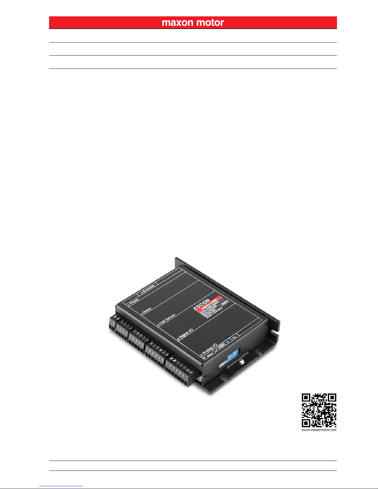
ESCON 50/5
Servo Controller
P/N 409510
Hardware Reference
Document ID: rel4285

maxon motor control
A-2 Document ID: rel4285 ESCON Servo Controller
Edition: September 2013 ESCON 50/5 Hardware Reference
© 2013 maxon motor. Subject to change without prior notice.
1 About 3
1.1 About this Document . . . . . . . . . . . . . . . . . . . . . . . . . . . . . . . . . . . . . . . . . . . . 3
1.2 About the Device . . . . . . . . . . . . . . . . . . . . . . . . . . . . . . . . . . . . . . . . . . . . . . . 4
1.3 About the Safety Precautions. . . . . . . . . . . . . . . . . . . . . . . . . . . . . . . . . . . . . . 5
2 Specifications 7
2.1 Technical Data . . . . . . . . . . . . . . . . . . . . . . . . . . . . . . . . . . . . . . . . . . . . . . . . . 7
2.2 Standards. . . . . . . . . . . . . . . . . . . . . . . . . . . . . . . . . . . . . . . . . . . . . . . . . . . . . 9
3 Setup 11
3.1 Generally applicable Rules. . . . . . . . . . . . . . . . . . . . . . . . . . . . . . . . . . . . . . . 11
3.2 Determination of Power Supply . . . . . . . . . . . . . . . . . . . . . . . . . . . . . . . . . . . 12
3.3 Connections . . . . . . . . . . . . . . . . . . . . . . . . . . . . . . . . . . . . . . . . . . . . . . . . . . 13
3.4 Potentiometers. . . . . . . . . . . . . . . . . . . . . . . . . . . . . . . . . . . . . . . . . . . . . . . . 26
3.5 Status Indicators. . . . . . . . . . . . . . . . . . . . . . . . . . . . . . . . . . . . . . . . . . . . . . . 26
4 Wiring 29
4.1 DC Motors . . . . . . . . . . . . . . . . . . . . . . . . . . . . . . . . . . . . . . . . . . . . . . . . . . . 30
4.2 EC Motors . . . . . . . . . . . . . . . . . . . . . . . . . . . . . . . . . . . . . . . . . . . . . . . . . . . 33
5Spare Parts 35
TABLE OF CONTENTS
READ THIS FIRST
These instructions are intended for qualified technical personnel. Prior comme ncing with any activities …
• you must carefully read and understand this manual and
• you must follow the instructions given therein.
The ESCON 50/5 is considered as partly completed machinery according to EU Directive 2006/42/EC, Article 2, Clause (g)
and is intended to be incorporated into or assembled with other machinery or other partly completed machinery or
equipment.
Therefore, you must not put the device into service, …
• unless you have made completely sure that the other ma chinery fully complies with the EU directive’s requirements!
• unless the other machinery fulfills all relevant health and safety aspects!
• unless all respective interfaces have been established and fulfill the herein stated requirements!
About
About this Document
maxon motor control
ESCON Servo Controller Document ID: rel4285
1-3
ESCON 50/5 Hardware Reference Edition: September 2013
© 2013 maxon motor. Subject to change without prior notice.
1 About
1.1 About this Document
1.1.1 Intended Purpose
The purpose of the present document is to familiarize you with the ESCON 50/5 Servo Controller. It will
highlight the tasks for safe and adequate installation and/or commissioning. Follow the described
instructions …
• to avoid dangerous situations,
• to keep installation and/or commissioning time at a minimum,
• to increase reliability and service life of the described equipment.
The document contains performance data and specifications, information on fulfilled standards, details
on connections and pin assignment, and wiring examples.
1.1.2 Target Audience
The present document is intended for trained and skilled personnel. It conveys information on how to
understand and fulfill the respective work and duties.
1.1.3 How to use
Take note of the following notations and codes which will be used throughout the document.
Table 1-1 Notation used
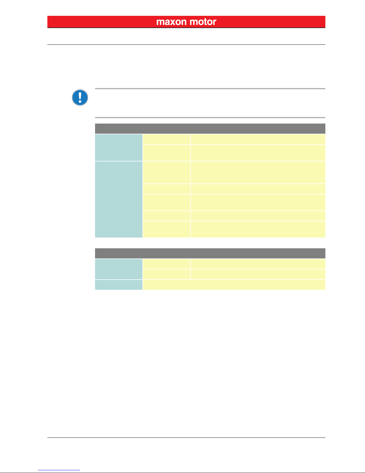
1.1.4 Symbols & Signs
In the course of the present document, the following symbols and sings will be used.
Notation Meaning
(n) refers to an item (such as order number, list item, etc.)
denotes “see”, “see also”, “take note of” or “go to”
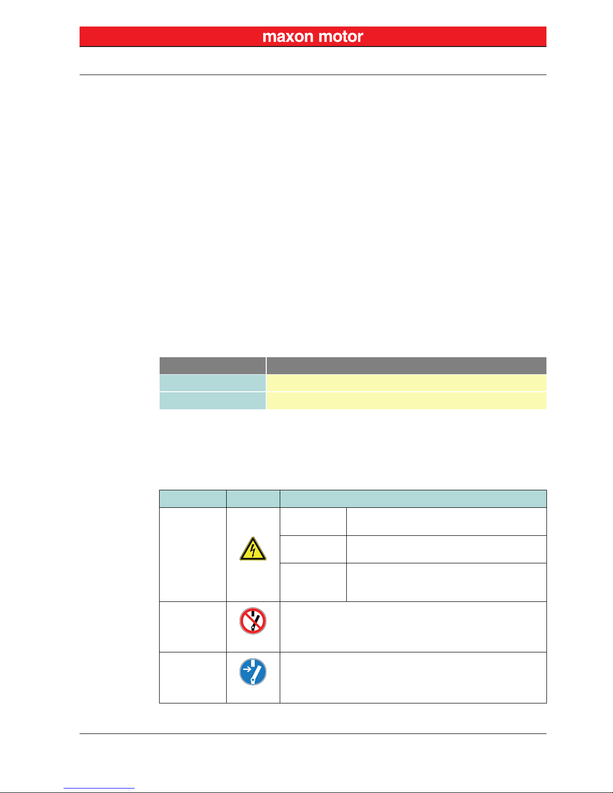
Type Symbol Meaning
Safety Alert
(typical)
DANGER
Indicates an imminent hazardous situation. If not
avoided, it will result in death or serious injury.
WARNING
Indicates a potential hazardous situation. If not
avoided, it can result in death or serious injury.
CAUTION
Indicates a probable hazardous situation or calls
the attention to unsafe practices. If not avoided, it
may result in injury.
Prohibited
Action
(typical)
Indicates a dangerous action. Hence, you must not!
Mandatory
Action
(typical)
Indicates a mandatory action. Hence, you must!

About
About the Device
maxon motor control
1-4 Document ID: rel4285 ESCON Servo Controller
Edition: September 2013 ESCON 50/5 Hardware Reference
© 2013 maxon motor. Subject to change without prior notice.
Table 1-2 Symbols & Signs
1.1.5 Trademarks and Brand Names
For easier legibility, registered brand names are listed below and will not be further tagged with their
respective trademark. It must be understood that the brands (the list below is not necessarily concluding) are protected by copyright and/or other intellectual property rights even if their legal trademarks are
omitted in the later course of this document.
Table 1-3 Brand Names and Trademark Owners
1.1.6 Copyright
© 2013 maxon motor. All rights reserved.
The present document – including all parts thereof – is protected by copyright. Any use (including repro-
duction, translation, microfilming, and other means of electronic data processing) beyond the narrow
restrictions of the copyright law without the prior approval of maxon motor ag, is not permitted and subject to prosecution under the applicable law.
1.2 About the Device
The ESCON 50/5 is a small-sized, powerful 4-quadrant PWM servo controller for the highly efficient control of permanent magnet-activated brushed DC motors or brushless EC motors up to approximately
250 Watts.
The featured operating modes – speed control (closed loop), speed control (open loop), and current
control – meet the highest requirements. The ESCON 50/5 is designed being commanded by an analog
set value and features extensive analog and digital I/O functionality.
The device is designed to be configured via USB interface using the graphical user interface «ESCON
Studio» for Windows PCs.
You can download the latest ESCON software version (as well as the latest edition of the documentation) from the internet under http://escon.maxonmotor.com.
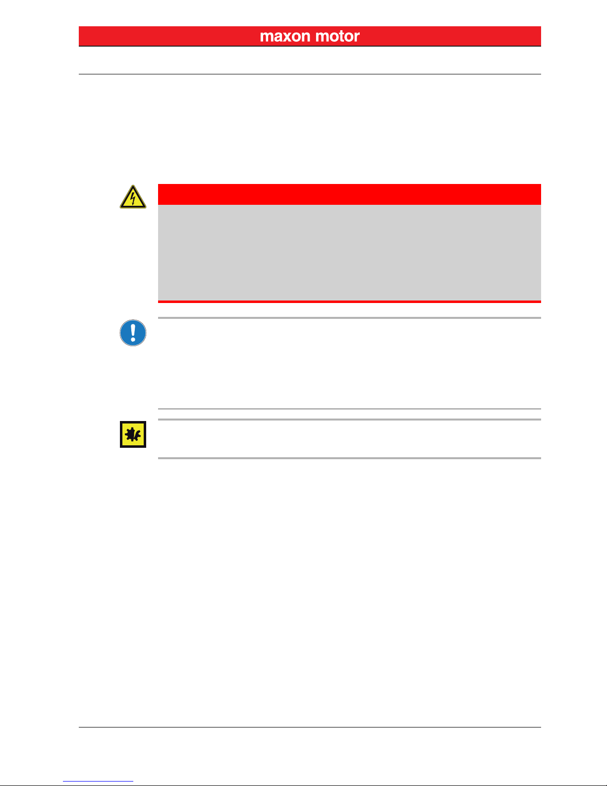
Information
Requirement /
Note / Remark
Indicates an activity you must perform prior
continuing, or gives information on a particular item
you need to observe.
Best Practice
Indicates an advice or recommendation on the
easiest and best way to further proceed.
Material
Damage
Indicates information particular to possible damage
of the equipment.
Brand Name Trademark Owner
Windows® © Microsoft Corporation, USA-Redmond, WA
maxon motor ag
Brünigstrasse 220
P.O.Box 263
CH-6072 Sachseln
Phone
Fax
Web
+41 41 666 15 00
+41 41 666 16 50
www.maxonmotor.com
Type Symbol Meaning
About
About the Safety Precautions
maxon motor control
ESCON Servo Controller Document ID: rel4285
1-5
ESCON 50/5 Hardware Reference Edition: September 2013
© 2013 maxon motor. Subject to change without prior notice.
1.3 About the Safety Precautions
• Make sure that you have read and understood the note “READ THIS FIRST” on page A-2!
• Do not engage with any work unless you possess the stated skills (chapter “1.1.2 Target
Audience” on page 1-3)!
• Refer to chapter “1.1.4 Symbols & Signs” on page 1-3 to understand the subsequently used
indicators!
• You must observe any regulation applicable in the country and/or at the site of implementation
with regard to health and safety/accident prevention and/or environmental protection!
Requirements
• Make sure that all associated devices and components are installed according to local regulations.
• Be aware that, by principle, an electronic apparatus can not be considered fail-safe. Therefore, you
must make sure that any machine/apparatus has been fitted with independent monitoring and safety
equipment. If the machine/apparatus should break down, if it is operated incorrectly, if the control unit
breaks down or if the cables break or get disconnected, etc., the complete drive system must return –
and be kept – in a safe operating mode.
• Be aware that you are not entitled to perform any repair on components supplied by maxon motor.
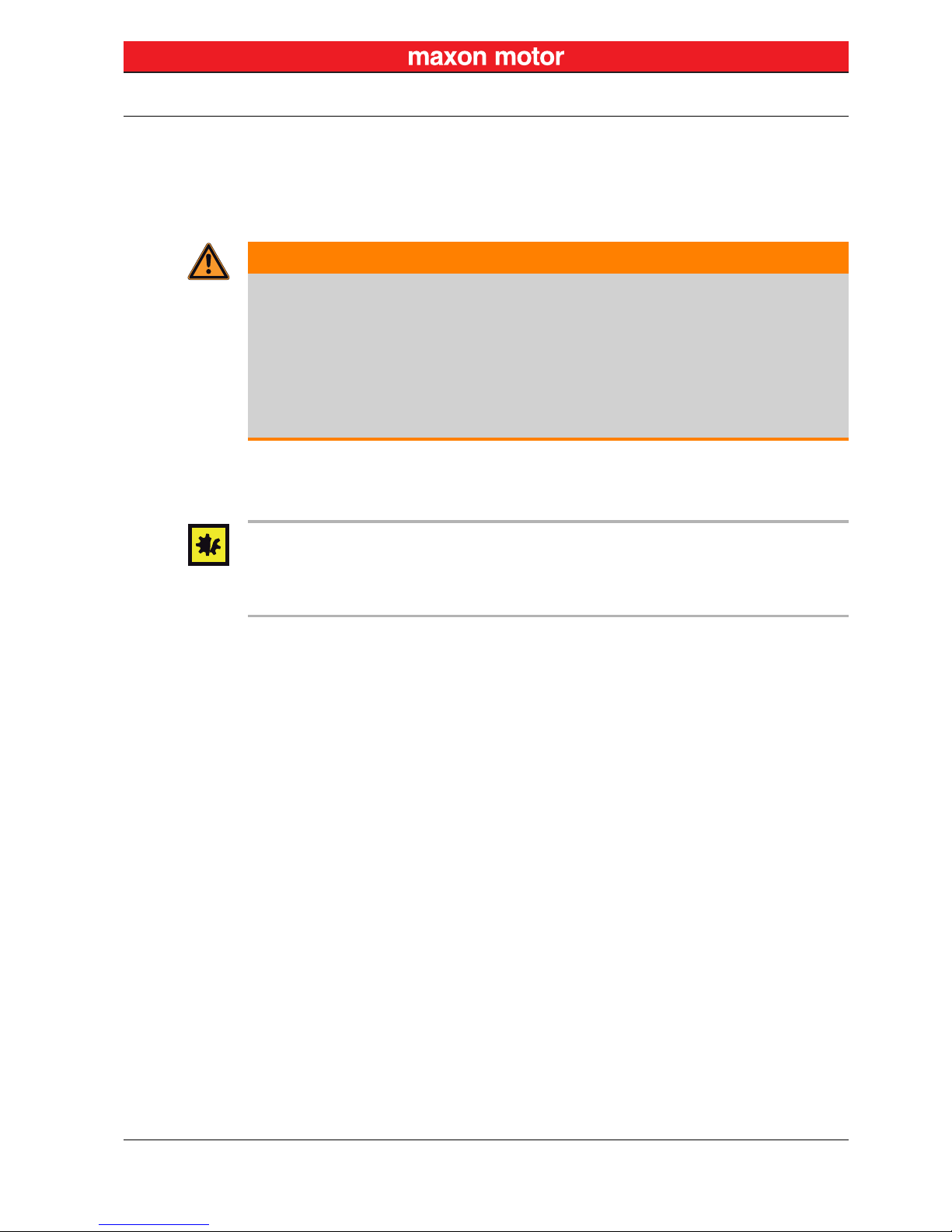
Electrostatic Sensitive Device (ESD)
• Make sure to wear working cloth in compliance with ESD.
• Handle device with extra care.
DANGER
High Voltage and/or Electrical Shock
Touching live wires causes death or serious injuries!
• Consider any power cable as connected to life power, unless having proven the opposite!
• Make sure that neither end of cable is connected to life power!
• Make sure that power source cannot be engaged while work is in process!
• Obey lock-out/tag-out procedures!
• Make sure to securely lock any power engaging equipment against unintentional engagement and
tag it with your name!

About
About the Safety Precautions
maxon motor control
1-6 Document ID: rel4285 ESCON Servo Controller
Edition: September 2013 ESCON 50/5 Hardware Reference
© 2013 maxon motor. Subject to change without prior notice.
••page intentionally left blank••
Specifications
Technical Data
maxon motor control
ESCON Servo Controller Document ID: rel4285
2-7
ESCON 50/5 Hardware Reference Edition: September 2013
© 2013 maxon motor. Subject to change without prior notice.
2 Specifications
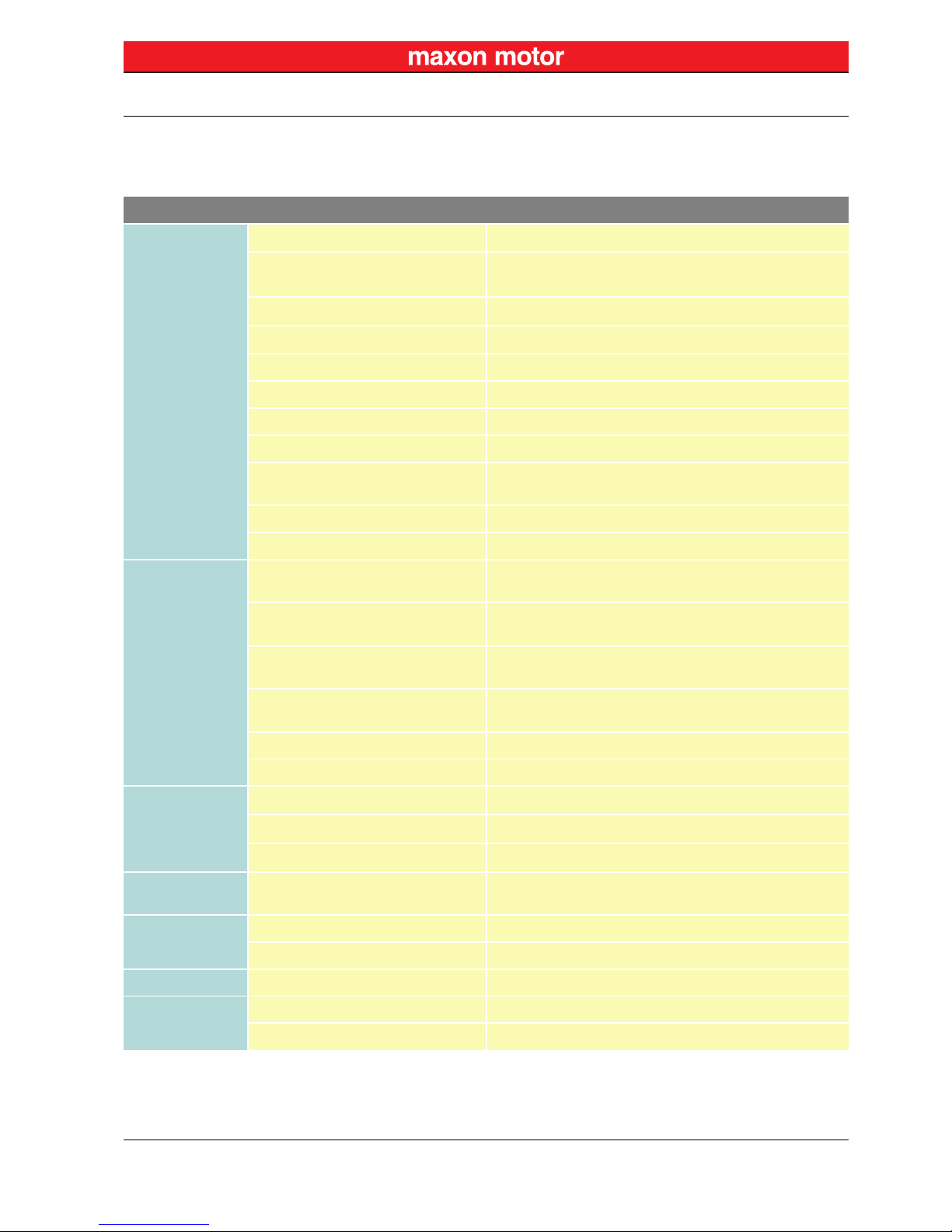
2.1 Technical Data
ESCON 50/5 (409510)
Electrical Rating
Nominal operating voltage +V
CC
10…50 VDC
Absolute operating voltage
+V
CC min
/ +V
CC max
8 VDC / 56 VDC
Output voltage (max.)
0.98 x +V
CC
Output current I
cont
/ I
max
(<20 s)
5 A / 15 A
Pulse Width Modulation frequency 53.6 kHz
Sampling rate PI current controller 53.6 kHz
Sampling rate PI speed controller 5.36 kHz
Max. efficiency 95%
Max. speed DC motor
limited by max. permissible speed (motor) and max. output
voltage (controller)
Max. speed EC motor 150’000 rpm (1 pole pair)
Built-in motor choke 3 x 30 μH; 5 A
Inputs & Outputs
Analog Input 1
Analog Input 2
resolution 12-bit; –10…+10 V; differential
Analog Output 1
Analog Output 2
resolution 12-bit; –4…+4 V; referenced to GND
Digital Input 1
Digital Input 2
+2.4…+36 VDC (Ri = 38.5 kΩ)
Digital Input/Output 3
Digital Input/Output 4
+2.4…+36 VDC (Ri = 38.5 kΩ) / max. 36 VDC (IL <500 mA)
Hall sensor signals H1, H2, H3
Encoder signals A, A\, B, B\, (max. 1 MHz)
Voltage Outputs
Auxiliary output voltage
+5 VDC (IL ≤10 mA)
Hall sensor supply voltage
+5 VDC (IL ≤30 mA)
Encoder supply voltage
+5 VDC (IL ≤70 mA)
Potentiometers
Potentiometer P1 (on board)
Potentiometer P2 (on board)
240°; linear
Motor
Connections
DC motor + Motor, – Motor
EC motor Motor winding 1, Motor winding 2, Motor winding 3
Interface USB 2.0 full speed (12 Mbit/s)
Status Indicators
Operation green LED
Error red LED
Specifications
Technical Data
maxon motor control
2-8 Document ID: rel4285 ESCON Servo Controller
Edition: September 2013 ESCON 50/5 Hardware Reference
© 2013 maxon motor. Subject to change without prior notice.
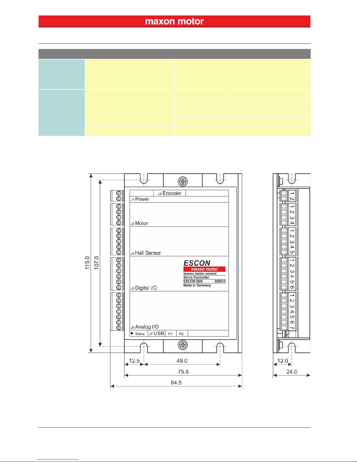
Table 2-4 Technical Data
Figure 2-1 Dimensional Drawing [mm]
Physical
Weight approx. 204 g
Dimensions (L x W x H) 115 x 75.5 x 24 mm
Mounting holes for M4 screws
Environmental
Conditions
Temperature
Operation –30…+45°C
Extended range
*1)
+45…+85°C
Derating: –0.113 A/°C
Storage –40…+85°C
Humidity 20…80% (condensation not permitted)
Remark: *1) Operation within the extended temperature range is permitted. However, a respective derating (declination of
max. output current) as to the stated value will apply.
ESCON 50/5 (409510)
Specifications
Standards
maxon motor control
ESCON Servo Controller Document ID: rel4285
2-9
ESCON 50/5 Hardware Reference Edition: September 2013
© 2013 maxon motor. Subject to change without prior notice.
2.2 Standards
The described device has been successfully tested for compliance with the below listed standards. In
practical terms, only the complete system (the fully operational equipment comprising all individual components, such as motor, servo controller, power supply unit, EMC filter, cabling etc.) can undergo an
EMC test to ensure interference-free operation.
Important Notice
The device’s compliance with the mentioned standards does not imply its compliance within the final,
ready to operate setup. In order to achieve compliance of your operational system, you must perform
EMC testing of the involved equipment as a whole.
Table 2-5 Standards
Electromagnetic Compatibility
Generic Standards
IEC/EN 61000-6-2 Immunity for industrial environments
IEC/EN 61000-6-3
Emission standard for residential, commercial and lightindustrial environments
Applied Standards
IEC/EN 61000-6-3
IEC/EN 55022
(CISPR22)
Radio disturbance characteristics / radio interference
IEC/EN 61000-4-2 Electrostatic discharge immunity test 8 kV/6 kV
IEC/EN 61000-4-3
Radiated, radio-frequency, electromagnetic field immunity
test >10 V/m
IEC/EN 61000-4-4 Electrical fast transient/burst immunity test ±2 kV
IEC/EN 61000-4-6
Immunity to conducted disturbances, induced by radiofrequency fields 10 Vrms
Others
Environmental
Standards
IEC/EN 60068-2-6 Environmental testing – Test Fc: Vibration (sinusoidal)
MIL-STD-810F Random transport
Safety Standards UL File Number E207844; unassembled printed circuit board

Specifications
Standards
maxon motor control
2-10 Document ID: rel4285 ESCON Servo Controller
Edition: September 2013 ESCON 50/5 Hardware Reference
© 2013 maxon motor. Subject to change without prior notice.
••page intentionally left blank••
Setup
Generally applicable Rules
maxon motor control
ESCON Servo Controller Document ID: rel4285
3-11
ESCON 50/5 Hardware Reference Edition: September 2013
© 2013 maxon motor. Subject to change without prior notice.
3Setup
IMPORTANT NOTICE: PREREQUISITES FOR PERMISSION TO COMMENCE INSTALLATION
The ESCON 50/5 is considered as partly completed machinery according to EU Directive 2006/42/EC,
Article 2, Clause (g) and is intended to be incorporated into or assembled with other machinery or
other partly completed machinery or equipment.
3.1 Generally applicable Rules
Maximal permitted Supply Voltage
• Make sure that supply power is between 10…50 VDC.
• Supply voltages above 56 VDC, or wrong polarity will destroy the unit.
• Note that the necessary output current is depending on the load torque. Yet, the output current limits
of the ESCON 50/5 are as follows; continuous max. 5 A / short-time (acceleration) max. 15 A.
WARNING
Risk of Injury
Operating the device without the full compliance of the surrounding system with the EU Directive 2006/42/EC may cause serious injuries!
• Do not operate the device, unless you have made completely sure that the other machinery fully
complies with the EU directive’s requirements!
• Do not operate the device, unless the other machinery fulfills all relevant health and safety
aspects!
• Do not operate the device, unless all respective interfaces have been established and fulfill the
requirements stated in this document!

Setup
Determination of Power Supply
maxon motor control
3-12 Document ID: rel4285 ESCON Servo Controller
Edition: September 2013 ESCON 50/5 Hardware Reference
© 2013 maxon motor. Subject to change without prior notice.
3.2 Determination of Power Supply
Basically, any power supply may be used, provided it meets the minimal requirements stated below.
1) Use the formula below to calculate the required voltage under load.
2) Choose a power supply according to the calculated voltage. Thereby consider:
a) During braking of the load, the power supply must be capable of buffering the recovered
kinetic energy (for example, in a capacitor).
b) If you are using an electronically stabilized power supply, make sure that the overcurrent
protection circuit is configured inoperative within the operating range.
Note
The formula already takes the following into account:
• Maximum PWM duty cycle of 98%
• Controller’s max. voltage drop of 1 V @ 5 A
K
NOWN VALUES:
• Operating torque M [mNm]
• Operating speed n [rpm]
• Nominal motor voltage U
N
[Volt]
• Motor no-load speed at U
N
, n0 [rpm]
• Speed/torque gradient of the motor Δn/ΔM [rpm/mNm]
S
OUGHT VALUE:
• Supply voltage +V
CC
[Volt]
S
OLUTION:
Power Supply Requirements
Output voltage
+VCC 10…50 VDC
Absolute output voltage min. 8 VDC; max. 56 VDC
Output current
Depending on load
(continuous max. 5 A; short-time (acceleration) max. 15 A (<20 s)
V
CC
U
N
n
O
-------
n
Δn
ΔM
-------- -
M⋅+
1
0.98
----------
⋅⋅1 V[]+≥
 Loading...