

maxon motor 380200 Instructions Manual
maxon motor
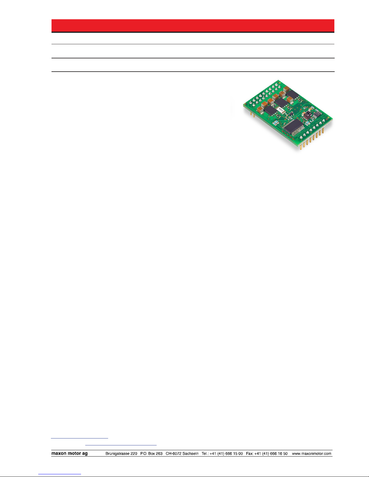
maxon motor control 1-Q-EC Amplifier DEC Module 50/5
Order number 380200
Operating Instructions Edition April 2015
The DEC Module 50/5 (Digital EC Controller) is a small
1-quadrant digital controller for the control of brushless DC motors
(Electronic Commutated motors) up to 250 W.
The used EC motor must be equipped with digital Hall sensors.
Features:
• Digital speed control
operates as «closed loop» or as «open loop» speed controller
• Maximum speed 80 000 rpm (motor with 1 pole pair)
• Set value input through external analogue voltage (0 ... +5 V)
• 3 different speed ranges selectable
• Direction of rotation preset by a digital signal
• The output stage can be enabled or disabled
• Maximum output current limit adjustable up to 10 A
• Motor speed can be monitored with the «Monitor n» output
• Status indication via «Ready»output
• Blockage protection (current limit for blocked motor)
• Protective functions: undervoltage, overvoltage and thermal overload
• Standardized connector strip, pitch 2.54 mm
Thanks to the wide input power supply range of 6...50 VDC (optional 5 VDC operation possible), the DEC Module
50/5 is very versatile and can be used with various power supplies.
A sturdy PI speed controller design is an ideal premise for immediate operation.
The well-priced and miniaturized OEM module seamlessly integrates into applications. Now the customer can
fully focus on developing his/hers own device - while being able to make use of maxon motor‘s vast drive knowhow. For start-up maxon motor offers a comprehensive Evaluation Board.
The latest edition of these operating instructions may be downloaded from the internet as a PDF-file under
www.maxonmotor.com, category «Service & Downloads», order number 380200 or
in the e-shop http://shop.maxonmotor.com.
Table of Contents
1 Safety Instructions ............................................................................................................................................. 2
2 Technical Data ................................................................................................................................................... 3
3 Pin assignment DEC Module 50/5 ..................................................................................................................... 5
4 Commissioning Instructions............................................................................................................................... 6
5 Functional Description of Inputs and Outputs.................................................................................................... 7
6 Protective functions ......................................................................................................................................... 14
7 Block Diagram ................................................................................................................................................. 15
8 Dimensional Drawing ....................................................................................................................................... 16
9 Accessories (not included in delivery) ............................................................................................................. 16
10 Appendix «Motherboard Design Guide» ....................................................................................................... 16

maxon motor
2 maxon motor control
1-Q-EC Amplifier DEC Module 50/5 Operating Instructions
April 2015 Edition / document number 1094861_PDF_E - 05 / subject to change
1 Safety Instructions
Skilled Personnel
Installation and commissioning of the equipment shall only be performed by
experienced, skilled personnel.
Statutory Regulations
The user must ensure that the amplifier and the components belonging to it
are assembled and connected according to local statutory regulations.
Disconnect Load
For primary operation the motor should be free running, i.e. with load disconnected.
Additional Safety Equipment
Any electronic apparatus is, in principle, not fail-safe. Machines and apparatus must therefore be fitted with independent monitoring and safety equipment. If the equipment breaks down, if it is operated incorrectly, if the control
unit breaks down or if the cables break, etc., it must be ensured that the drive
or the complete apparatus is kept in a safe operating mode.
Repairs
Repairs may be made by authorized personnel only or by the manufacturer.
Improper repairs can result in substantial dangers for the user
Danger
During installation of the DEC Module, make sure to disconnect all apparatus
from the electrical supply.
After switch-on, do not touch any life parts!
Wiring Procedure
All electrical connections should only be connected or disconnected when the
power is switched off.
Max. Supply voltage
Make sure that the supply voltage is between 6 and 55 VDC. Voltage higher
than 56 VDC or wrong polarity will destroy the unit.
Short Circuit and Earth Fault
The amplifier is not protected against winding short circuits against ground
safety earth and/or GND!
Electrostatic sensitive device (ESD)
a
a
a
a
a
a
a
a
a
a

maxon motor control 3
maxon motor
Operating Instructions 1-Q-EC Amplifier DEC Module 50/5
April 2015 Edition / document number 1094861_PDF_E - 05 / subject to change
2 Technical Data
2.1 Electrical data
Nominal supply voltage +VCC ..................................................................... 6 … 50 VDC (optional 5 VDC1)
Absolute minimum supply voltage +V
cc min
........................................................... 6 VDC (optional 5 VDC1)
Absolute maximum supply voltage +V
cc max
.................................................................................... 55 VDC
Max. output voltage ...................................................................................................................... 0.95 • V
CC
Continuous output current I
cont
................................................................................................................5 A
Max. output current I
max
.........................................................................................................................10 A
Switching frequency.......................................................................................................................46.8 kHz
Max. speed (motor with 1 pole pair) ......................................................................................... 80 000 rpm
2.2 Inputs
«Set value speed» ........................................................Analogue input (0 ... 5 V); Resolution: 1024 steps
«Enable» ......................................................................+2.4 … +55 V (Ri = 100 kΩ) or switch against V
CC
«Direction» ...................................................................+2.4 … +55 V (Ri = 100 kΩ) or switch against V
CC
Speed range «DigIN1 » ...............................+2.4 … +55 V (R
pull-up
= 47 kΩ at 5 V) or switch against Gnd
Speed range «DigIN2 » ...............................+2.4 … +55 V (R
pull-up
= 47 kΩ at 5 V) or switch against Gnd
«Set current limit» .............................................................................external resistor (1/16 W) against Gnd
Hall sensors ................................................................ «Hall sensor 1», «Hall sensor 2», «Hall sensor 3»
2.3 Output
Motor speed «Monitor n» ............................................................... Digital output signal, 5 V (Ro = 47 kΩ)
Status indication «Ready» .............................................................. Digital output signal, 5 V (Ro = 47 kΩ)
2.4 Voltage output
+5 VDC output voltage «VCC Hall» ............................................................................+5 VDC, max. 35 mA
2.5 Motor connections
Motor connections ...................................... «Motor winding 1», « Motor winding 2», « Motor winding 3»
2.6 Ambient temperature
Operation .................................................................................................................................-10 ... +45°C
Storage .....................................................................................................................................-40 ... +85°C
2.7 Humidity range
Non condensating .......................................................................................................................20 ... 80 %
2.8 Protective functions
Current limitation (cycle-by-cycle) ........................................................... adjustable up to maximum 10 A
Blockage ........................................................................Motor current limitation if motor shaft is blocked
Undervoltage shutdown ....................................................................................... shutdown if VCC < 6 VDC
Overvoltage shutdown ....................................................................................... shutdown if VCC > 56 VDC
Thermal overload protection of power stage ..............................................shutdown if T
power stage
> 100°C
2.9 Mechanical data
Weight ........................................................................................................................................ approx. 9 g
Dimensions (LxWxH). ......................................................................................... 43.18 x 27.94 x 12.7 mm
....................................................................................................................................... 1.7 x 1.1 x 0.5 Inch
2.10 Terminals
Pin header 1 ..................................................................................................................................2 x 9 pins
.......................................................................................................... double-row, pitch 2.54 mm (0.1 Inch)
Pin header 2 ....................................................................................................................................... 8 pins
............................................................................................................ single row, pitch 2.54 mm (0.1 Inch)
1 5V operating see chapter «10.8.2 Low Voltage +5V operation»

maxon motor
4 maxon motor control
1-Q-EC Amplifier DEC Module 50/5 Operating Instructions
April 2015 Edition / document number 1094861_PDF_E - 05 / subject to change
2.11 Standards
The described device has been successfully tested for compliance with the
below listed standards. In practical terms, only the complete system (the fully
operational equipment comprising all individual components, such as motor,
servo controller, power supply unit, EMC filter, cabling etc.) can undergo an
EMC test to ensure interference-free operation.
Important Notice
a The device’s compliance with the mentioned standards does not im-
ply its compliance within the final, ready to operate setup. In order to
achieve compliance of your operational system, you must perform EMC
testing of the involved equipment as a whole.
Electromagnetic compatibility
Generic
standards
IEC/EN 61000-6-2 Immunity for industrial environments
IEC/EN 61000-6-4
Emission standard for industrial environments
Applied
standards
IEC/EN 61000-6-4
EN 55011
(CISPR11)
RF disturbances
IEC/EN 61000-4-3 Radiated electromagnetic field > 10V/m
IEC/EN 61000-4-4 Electrical fast transient burst +/- 2 kV
IEC/EN 61000-4-6 RF conducted disturbances 10Vrms
IEC/EN 61000-4-8 Power frequency magnetic field 30A/m
Others
Safety
standards
UL File Number E172472, E92481 or E76251; unassembled
printed circuit board
Reliability MIL-HDBK-217F
Reliability prediction of electronic equipment
Environment: Ground, benign (GB)
Ambient temperature: 298 K (25°C)
Component stress: In accordance with circuit diagram and nominal power
Mean Time Between Failures (MTBF):
1‘434‘315 hours
maxon motor control 5
maxon motor
Operating Instructions 1-Q-EC Amplifier DEC Module 50/5
April 2015 Edition / document number 1094861_PDF_E - 05 / subject to change
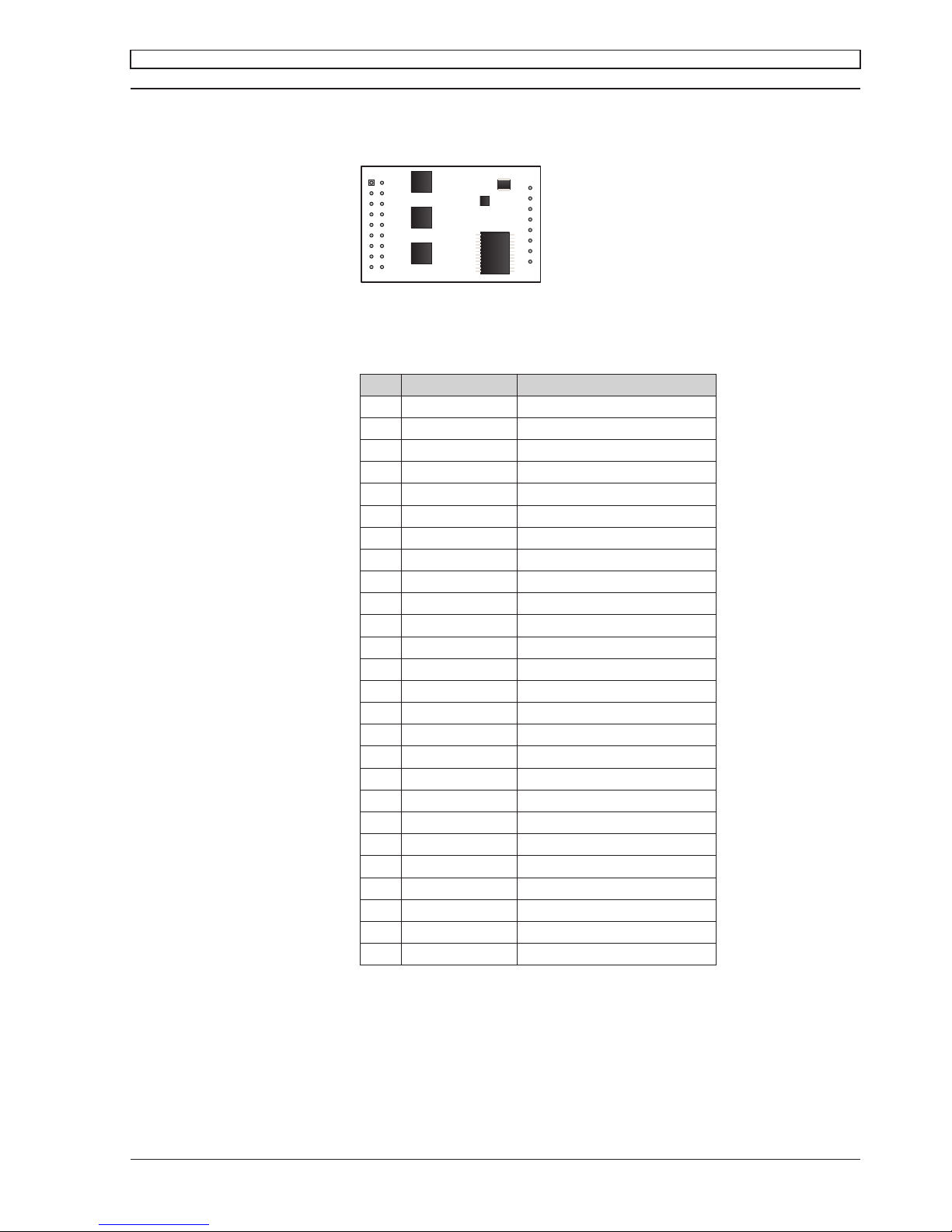
3 Pin assignment DEC Module 50/5
Top view
3.1 Pin assignment
Pin Signal Description
1 W1 Motor winding 1
2 W1 Motor winding 1
3 W2 Motor winding 2
4 W2 Motor winding 2
5 W3 Motor winding 3
6 W3 Motor winding 3
7 +V
cc
Supply voltage 6...50 VDC
8 +V
cc
Supply voltage 6...50 VDC
9 Gnd Ground
10 Gnd Ground
11 Vcc Hall +5 VDC output voltage
12 n.c. do not connect
13 H1 Hall sensor 1
14 Gnd Ground
15 H2 Hall sensor 2
16 Gnd Ground
17 H3 Hall sensor 3
18 Monitor n Speed monitor output
19 Ready Status indication output
20 DigIN1 Digital input 1
21 DigIN2 Digital input 2
22 Enable Enable input
23 Direction Direction input
24 Gnd Ground
25 Set current limit Set current limit input
26 Set value speed Set value speed input
1
2
17 18
19
26
DEC Module 50/5

maxon motor
6 maxon motor control
1-Q-EC Amplifier DEC Module 50/5 Operating Instructions
April 2015 Edition / document number 1094861_PDF_E - 05 / subject to change
4 Commissioning Instructions
4.1 Power supply layout
Any available power supply can be used, as long as it meets the minimum
requirements shown below.
During commissioning and adjustment phases, we recommend to mechanically separate the motor from the machine to prevent damage due to uncontrolled motion!
Power supply requirements
Nominal output voltage 6 VDC < V
CC
< 50 VDC
Absolute minimum output voltage 6 VDC
Absolute maximum output voltage 55 VDC
Output current depending on load, continuous max. 5 A
acceleration, short-time max. 10 A
The required supply voltage can be calculated as follows:
Known values
Ö Operating torque MB [mNm]
Ö Operating speed nB [rpm]
Ö Nominal motor voltage UN [V]
Ö Motor no-load speed at UN, n0 [rpm]
Ö Speed/torque gradient of the motor Dn/DM [rpm/mNm]
Sought value
Ö Supply voltage VCC [V]
Solution
VM
M
n
n
n
U
V
BB
o
N
cc
3.0
95.0
1
¸
¹
·
¨
©
§
'
'
Select a power supply capable of supplying this calculated voltage under
load. The formula takes into account a maximum PWM duty cycle of 95%
and a 0.3 V maximum voltage drop (at maximum output current) of the power
stage.
What speed can be reached with a given power supply:
»
¼
º
«
¬
ª
'
'
»
¼
º
«
¬
ª
B
N
ccB
M
M
n
U
n
VVn
0
3.095.0
Note
Ö During controlled deceleration, the power supply must be able to buffer
the back-fed energy e.g. in a capacitor.
Ö The under voltage protection switches off the DEC Module 50/5, as soon
as the supply voltage VCC drops below 6 V. Therefore, at low supply voltage VCC attention has to be payed to the voltage drop over the supplying
cables.

maxon motor control 7
maxon motor
Operating Instructions 1-Q-EC Amplifier DEC Module 50/5
April 2015 Edition / document number 1094861_PDF_E - 05 / subject to change
5 Functional Description of Inputs and Outputs
5.1 Inputs
5.1.1 Speed range and mode selection with «DigIN1» and «DigIN2»
The digital inputs «DigIN1» [20] and «DigIN2» [21] determine both, the operation mode (digital speed controller or digital speed actuator) and the speed
range in speed set value mode.
Motor type
DigIN1 DigIN2 1 pole pair 4 pole pair 8 pole pair
0 0
Open loop speed control, 0...95 % PWM
depending on the «Set value speed» input voltage
1 0
500...5 000 rpm 125...1 250 rpm 62...625 rpm
0 1
500...20 000 rpm 125... 5 000 rpm 62...2 500 rpm
1 1
500...80 000 rpm 125...20 000 rpm 62...10 000 rpm
Please note
Ö If the signal level of the digital inputs DigIN1 [20] and DigIN2 [21] are
changed, the new levels are adopted by a disable-enable procedure.
If the input «DigIN» is not connected (floating) or a voltage higher than 2.4 V
is applied, the input is active.
Logic 1
Input not connected (floating)
Input voltage > 2.4 V
Input active
If the input «DigIN» is set to ground potential or a voltage smaller than 0.8 V
is applied, the digital input is inactive
Logic 0 Input set to Gnd
Input voltage < 0.8 V
Input inactive
The inputs «DigIN1»and «DigIN2» are protected against overvoltage.
Digital input 1 Pin number [20] «DigIN1»
Digital input 2 Pin number [21] «DigIN2»
Input voltage range 0 ... +5 V
Input impedance 47 kΩ pull-up resistor against 5 V
Continuous overvoltage protection -55 ... +55 V
 Loading...