

Page 1

maxon motor
maxon motor control 1-Q-EC Amplifier DEC Module 24/2
Order number 367661
Operating Instructions Edition April 2015
The DEC Module 24/2 (Digital EC Controller) is a small
1-quadrant digital controller for the control of brushless DC motors
(Electronic Commutated motors) up to 48 W.
The used EC motor must be equipped with digital Hall sensors.
Features:
• Digital speed control
operates as «closed loop» or as «open loop» speed controller
• Maximum speed 80 000 rpm (motor with 1 pole pair)
• Set value input through external analogue voltage (0 ... +5 V)
• 3 different speed ranges selectable
• Direction of rotation preset by a digital signal
• The output stage can be enabled or disabled
• Maximum output current limit adjustable up to 3 A
• Status indication via «Ready»output
• Blockage protection (current limit for blocked motor)
• Protective functions: undervoltage, overvoltage and thermal overload
• Standardized connector strip, pitch 2.54 mm
Thanks to the wide input power supply range of 8...24 VDC (optional 5 VDC operation possible), the DEC Module
24/2 is very versatile and can be used with various power supplies.
A sturdy PI speed controller design is an ideal premise for immediate operation.
The well-priced and miniaturized OEM module seamlessly integrates into applications. Now the customer can
fully focus on developing his/hers own device - while being able to make use of maxon motor‘s vast drive knowhow. For start-up maxon motor offers a comprehensive Evaluation Board.
The latest edition of these operating instructions may be downloaded from the internet as a PDF-file under
www.maxonmotor.com, category «Service & Downloads», order number 367661 or
in the e-shop http://shop.maxonmotor.com.
Table of Contents
1 Safety Instructions ............................................................................................................................................. 2
2 Technical Data ................................................................................................................................................... 3
3 Pin assignment DEC Module 24/2 ..................................................................................................................... 5
4 Commissioning Instructions............................................................................................................................... 6
5 Functional Description of Inputs and Outputs.................................................................................................... 7
6 Protective functions ......................................................................................................................................... 13
7 Block Diagram ................................................................................................................................................. 14
8 Dimensional Drawing ....................................................................................................................................... 15
9 Accessories (not included in delivery) ............................................................................................................. 15
10 Appendix «Motherboard Design Guide» ....................................................................................................... 16
Page 2

maxon motor
2 maxon motor control
1-Q-EC Amplifier DEC Module 24/2 Operating Instructions
April 2015 Edition / document number 1002422_PDF_E - 04 / subject to change
1 Safety Instructions
Skilled Personnel
Installation and starting of the equipment shall only be performed by experienced, skilled personnel.
Statutory Regulations
The user must ensure that the amplifier and the components belonging to it
are assembled and connected according to local statutory regulations.
Load Disconnected
For primary operation the motor should be free running, i.e. with load disconnected.
Additional Safety Equipment
Any electronic apparatus is, in principle, not fail-safe. Machines and apparatus must therefore be fitted with independent monitoring and safety equipment. If the equipment breaks down, if it is operated incorrectly, if the control
unit breaks down or if the cables break, etc., it must be ensured that the drive
or the complete apparatus is kept in a safe operating mode.
Repairs
Repairs may be made by authorized personnel only or by the manufacturer.
Improper repairs can result in substantial dangers for the user
Danger
During installation of the DEC Module, make sure to disconnect all apparatus
from the electrical supply.
After switch-on, do not touch any life parts!
Wiring Procedure
All cable connections should only be connected or disconnected when the
power is switched off.
Max. Supply voltage
Make sure that the supply voltage is between 8 and 28 VDC. Voltage higher
than 30 VDC or wrong polarity will destroy the unit.
Short Circuit and Earth Fault
The amplifier is not protected against winding short circuits against ground
safety earth and/or GND!
Electrostatic sensitive device (ESD)
a
a
a
a
a
a
a
a
a
a
Page 3

maxon motor control 3
maxon motor
Operating Instructions 1-Q-EC Amplifier DEC Module 24/2
April 2015 Edition / document number 1002422_PDF_E - 04 / subject to change
2 Technical Data
2.1 Electrical data
Nominal supply voltage +VCC ..................................................................... 8 … 24 VDC (optional 5 VDC1)
Absolute minimum supply voltage +V
cc min
........................................................... 8 VDC (optional 5 VDC1)
Absolute maximum supply voltage +V
cc max
.................................................................................... 28 VDC
Max. output voltage .............................................................................................................................. +V
CC
Continuous output current I
cont
................................................................................................................2 A
Max. output current I
max
...........................................................................................................................3 A
Switching frequency.......................................................................................................................46.8 kHz
Max. speed (motor with 1 pole pair) ......................................................................................... 80 000 rpm
2.2 Inputs
«Set value speed» ........................................................Analogue input (0 ... 5 V); Resolution: 1024 steps
«Enable» ......................................................................+2.4 … +28 V (Ri = 100 kΩ) or switch against V
CC
«Direction» ...................................................................+2.4 … +28 V (Ri = 100 kΩ) or switch against V
CC
Speed range «DigIN1 » ...............................+2.4 … +28 V (R
pull-up
= 15 kΩ at 5 V) or switch against Gnd
Speed range «DigIN2 » ...............................+2.4 … +28 V (R
pull-up
= 15 kΩ at 5 V) or switch against Gnd
«Set current limit» .............................................................................external resistor (1/16 W) against Gnd
Hall sensors ................................................................ «Hall sensor 1», «Hall sensor 2», «Hall sensor 3»
2.3 Output
Status indication «Ready» ............................................................... Digital output signal, 5 V (Ri = 10 kΩ)
2.4 Voltage output
+5 VDC output voltage «VCC Hall» ............................................................................+5 VDC, max. 35 mA
2.5 Motor connections
Motor connections ...................................... «Motor winding 1», « Motor winding 2», « Motor winding 3»
2.6 Ambient temperature
Operation .................................................................................................................................-10 ... +45°C
Storage .....................................................................................................................................-40 ... +85°C
2.7 Humidity range
Non condensating .......................................................................................................................20 ... 80 %
2.8 Protective functions
Current limitation (cycle-by-cycle) ............................................................. adjustable up to maximum 3 A
Blockage ...................................... Motor current limitation if motor shaft is blocked for longer than 1.5 s
Undervoltage shutdown ....................................................................................shutdown if VCC < 6.5 VDC
Overvoltage shutdown ....................................................................................... shutdown if VCC > 30 VDC
Thermal overload protection of power stage ................................................ shutdown if T
power stage
> 95°C
2.9 Mechanical data
Weight ........................................................................................................................................ approx. 4 g
Dimensions (LxWxH). ............................................................................................24.2 x 20.38 x 12.7 mm
..................................................................................................................................... 0.95 x 0.8 x 0.5 Inch
2.10 Terminals
Pin header 1 ..................................................................................................................................... 9 poles
............................................................................................................ single row, pitch 2.54 mm (0.1 Inch)
Pin header 2 ..................................................................................................................................... 8 poles
............................................................................................................ single row, pitch 2.54 mm (0.1 Inch)
1 5V operating see chapter «10.8.2 Low Voltage +5V operation»
Page 4

maxon motor
4 maxon motor control
1-Q-EC Amplifier DEC Module 24/2 Operating Instructions
April 2015 Edition / document number 1002422_PDF_E - 04 / subject to change
2.11 Standards
The described device has been successfully tested for compliance with the
below listed standards. In practical terms, only the complete system (the fully
operational equipment comprising all individual components, such as motor,
servo controller, power supply unit, EMC filter, cabling etc.) can undergo an
EMC test to ensure interference-free operation.
Important Notice
a The device’s compliance with the mentioned standards does not im-
ply its compliance within the final, ready to operate setup. In order to
achieve compliance of your operational system, you must perform EMC
testing of the involved equipment as a whole.
Electromagnetic compatibility
Generic
standards
IEC/EN 61000-6-2 Immunity for industrial environments
IEC/EN 61000-6-3
Emission standard for residential, commercial and lightindustrial environments
Applied
standards
IEC/EN 61000-6-3
EN 55022
(CISPR22)
Radio disturbance characteristics/radio
interference
IEC/EN 61000-4-3 Radiated electromagnetic field > 10V/m
IEC/EN 61000-4-4 Electrical fast transient burst +/- 2 kV
IEC/EN 61000-4-6 RF conducted disturbances 10Vrms
IEC/EN 61000-4-8 Power frequency magnetic field 30A/m
Others
Safety
standards
UL File Number E76251; unassembled printed circuit board
Reliability MIL-HDBK-217F
Reliability prediction of electronic equipment
Environment: Ground, benign (GB)
Ambient temperature: 298 K (25°C)
Component stress: In accordance with circuit diagram and nominal power
Mean Time Between Failures (MTBF):
1'986'879 hours
Page 5
maxon motor control 5
maxon motor
Operating Instructions 1-Q-EC Amplifier DEC Module 24/2
April 2015 Edition / document number 1002422_PDF_E - 04 / subject to change
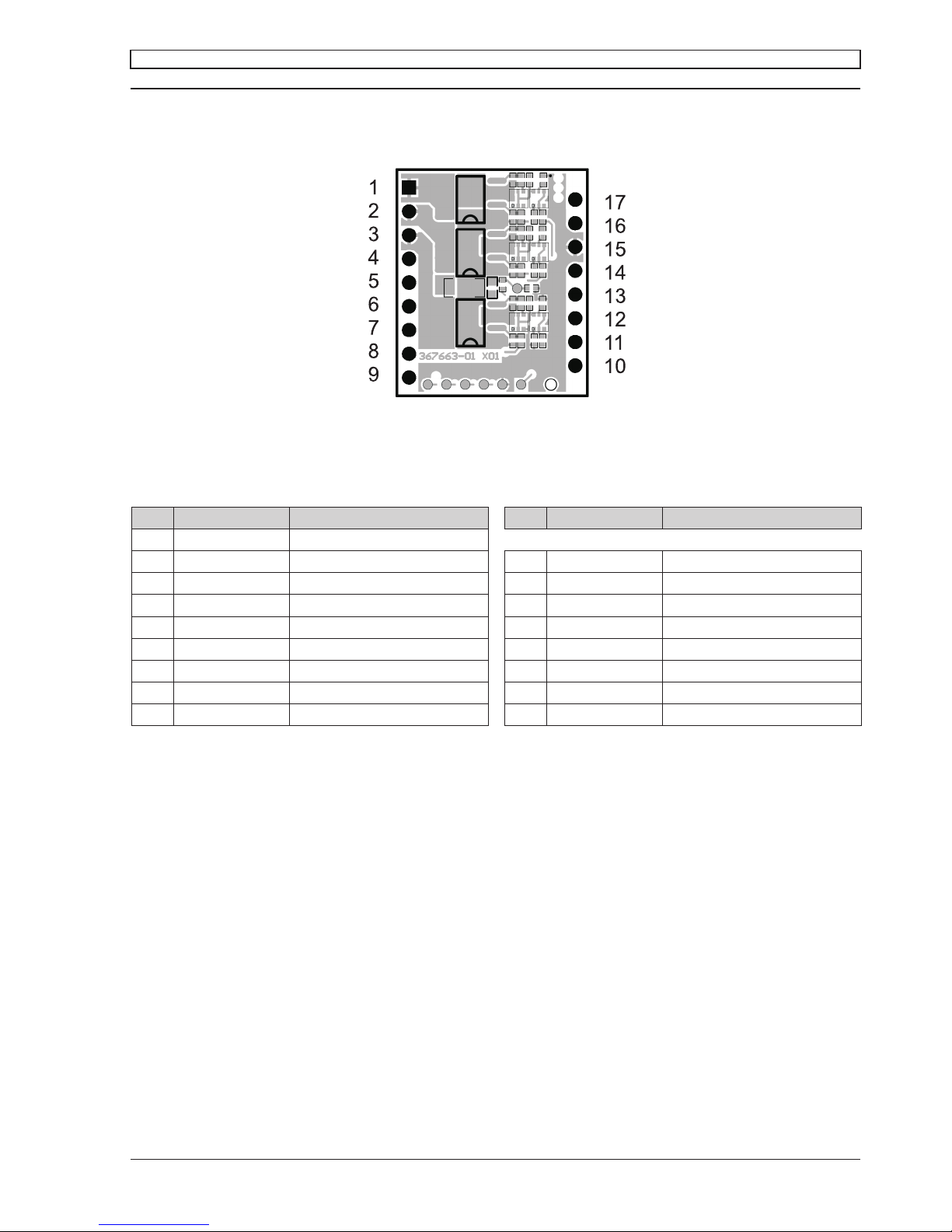
3 Pin assignment DEC Module 24/2
Top view
3.1 Pin assignment
Pin Signal Description Pin Signal Description
1 W1 Motor winding 1
2 W2 Motor winding 2 17 Set value speed Set value speed input
3 W3 Motor winding 3 16 Set current limit Set current limit input
4 +V
cc
Supply voltage 8...24 VDC 15 Gnd Ground
5 Gnd Ground 14 Direction Direction input
6 Vcc Hall +5 VDC output voltage 13 Enable Enable input
7 H1 Hall sensor 1 12 DigIN2 Digital input 2
8 H2 Hall sensor 2 11 DigIN1 Digital input 1
9 H3 Hall sensor 3 10 Ready Status indication output
Page 6

maxon motor
6 maxon motor control
1-Q-EC Amplifier DEC Module 24/2 Operating Instructions
April 2015 Edition / document number 1002422_PDF_E - 04 / subject to change
4 Commissioning Instructions
4.1 Power supply layout
Any available power supply can be used, as long as it meets the minimum
requirements shown below.
During set up and adjustment phases, we recommend to mechanically
separate the motor from the machine to prevent damage due to uncontrolled
motion!
Power supply requirements
Nominal output voltage 8 VDC < V
CC
< 24 VDC
Absolute minimum output voltage 8 VDC
Absolute maximum output voltage 28 VDC
Output current depending on load, continuous max. 2 A
acceleration, short-time max. 3 A
The required supply voltage can be calculated as follows:
Known values
Ö Operating torque MB [mNm]
Ö Operating speed nB [rpm]
Ö Nominal motor voltage UN [V]
Ö Motor no-load speed at UN, n0 [rpm]
Ö Speed/torque gradient of the motor Dn/DM [rpm/mNm]
Sought value
Ö Supply voltage VCC [V]
Solution
VM
M
n
n
n
U
V
BB
o
N
cc
5.0
¸
¹
·
¨
©
§
'
'
Select a power supply capable of supplying this calculated voltage under
load. The formula takes into account a 0.5 V maximum voltage drop (at maximum output current) of the power stage.
What speed can be reached with a given power supply:
»
¼
º
«
¬
ª
'
'
»
¼
º
«
¬
ª
B
N
ccB
M
M
n
U
n
VVn
0
5.0
Note
Ö The power supply must be able to buffer the back-fed energy e.g. in a
capacitor.
Ö The under voltage protection switches off the DEC Module 24/2, as soon
as the supply voltage VCC falls below 6.5 V. Therefore, at low supply voltage VCC attention has to be payed to the voltage drop over the supplying
cables.
Page 7

maxon motor control 7
maxon motor
Operating Instructions 1-Q-EC Amplifier DEC Module 24/2
April 2015 Edition / document number 1002422_PDF_E - 04 / subject to change
5 Functional Description of Inputs and Outputs
5.1 Inputs
5.1.1 Speed range and mode selection with «DigIN1» und «DigIN2»
The digital inputs «DigIN1» [11] and «DigIN2» [12] determine both, the operation mode (digital speed controller or digital speed actuator) and the speed
range in speed set value mode.
Motor type
DigIN1 DigIN2 1 pole pair 4 pole pair 8 pole pair
0 0
Open loop speed control, 0...100 % PWM
depending on the «Set value speed» input voltage
1 0
500...5 000 rpm 125...1 250 rpm 62...625 rpm
0 1
500...20 000 rpm 125... 5 000 rpm 62...2 500 rpm
1 1
500...80 000 rpm 125...20 000 rpm 62...10 000 rpm
Please note
Ö If the signal level of the digital inputs DigIN1 [11] and DigIN2 [12] are
changed, the new levels are adopted by a disable-enable procedure.
If the input «DigIN» is not connected (floating) or a voltage higher than 2.4 V
is applied, the input is active.
Logic 1
Input not connected (floating)
Input voltage > 2.4 V
Input active
If the input «DigIN» is set to ground potential or a voltage smaller than 0.8 V
is applied, the digital input is inactive
Logic 0 Input set to Gnd
Input voltage < 0.8 V
Input inactive
The inputs «DigIN1»and «DigIN2» are protected against over voltage.
Digital input 1 Pin number [11] «DigIN1»
Digital input 2 Pin number [12] «DigIN2»
Input voltage range 0 ... +5 V
Input impedance 15 kΩ pull-up resistor against 5 V
Continuous over voltage protection -28 ... +28 V
Page 8

maxon motor
8 maxon motor control
1-Q-EC Amplifier DEC Module 24/2 Operating Instructions
April 2015 Edition / document number 1002422_PDF_E - 04 / subject to change
5.1.2 Set value «Set value speed»
At the «Set value speed» input [17] the external analogue set value and
hence the rotational speed of the motor shaft is predetermined.
By adjusting the signal levels on digital inputs «DigIN1 [11]» and
«DigIN2 [12]» the speed range can be set in advance.
Motor type
DigIN1 DigIN2 1 pole pair 4 pole pair 8 pole pair
0 0
Open loop speed control, 0...100 % PWM
depending on the «Set value speed» input voltage
1 0
500...5 000 rpm 125...1 250 rpm 62...625 rpm
0 1
500...20 000 rpm 125...5 000 rpm 62...2 500 rpm
1 1
500...80 000 rpm 125...20 000 rpm 62...10 000 rpm
Note
Ö If the signal level of the digital inputs DigIN1 [11] and DigIN2 [12] are
changed, the new levels are adopted by a disable-enable procedure.
Set value voltage Description
0 V ... 0.1 V Operation at a minimum speed
0.1 V ... 5.0 V Linear speed adjustment
The actual speed value is calculated according the following formula:
Known values
Ö Minimum speed (see table above) n
min
[rpm]
Ö Maximum speed (see table above) n
max
[rpm]
Ö Set value voltage V
set
[V] respectively speed n [rpm]
Sought value
Ö speed n [rpm]
Sought value
Ö Set value voltage V
set
[V]
Solution
>@
>@
minminmax
9.4
1.0
nnn
V
VV
n
set
»
¼
º
«
¬
ª
Solution
>@
>@
VV
nn
nn
V
set
1.09.4
minmax
min
¸
¸
¹
·
¨
¨
©
§
The «Set value speed» input is protected against over voltage.
Set value speed input Pin number [17] «Set value speed»
Input voltage range 0 ... +5 V (referenced to Gnd)
Resolution 1024 steps (4.88 mV)
Input impedance 107 kΩ (in range 0 ... +5 V)
Continuous over voltage protection -28 ... +28 V
a The change rate of the set value signal is limited internally with a ramp
function. It nominally takes 1 s to reach the maximum speed for the
selected speed range. This time can be shortened proportionally by
defining smaller set value increments.
Page 9

maxon motor control 9
maxon motor
Operating Instructions 1-Q-EC Amplifier DEC Module 24/2
April 2015 Edition / document number 1002422_PDF_E - 04 / subject to change
Adjusting set values via PWM control
Instead of an analog voltage, a PWM signal with a fixed frequency and amplitude can be used to adjust the speed set value.
The desired change in the set value is achieved by variation of the duty cycle
in the range 0…100%. Both the amplitude and the duty cycle have an influence on the resulting speed. The mean value of the applied PWM voltage
corresponds to the analog input signal for the speed set value.
Nominal value amplitude PWM set value 0…5 V
Max. value amplitude PWM set value -28…+28 V
Frequency range PWM set value 500 Hz…20 kHz
Modulation PWM set value 0…100%
Continuous overvoltage protection -28…+28 V
Examples:
motor type: 1 pole pair
speed range: 500...20‘000 min
-1
>@
>@
minminmax
9.4
1.0
nnn
V
VV
n
set
»
¼
º
«
¬
ª
PWM cycle 1: 33 % PWM @ 0 V … 12 V à 4.0 V à 16'020 rpm
t [µs]
Voltage [V]
0
2.5
5
7.5
10
12.5
-2.5
20 40
60 80 100 120 140 160 180 200
220 240 260 280 300
PWM cycle 1
PWM cycle 2
PWM cycle 3
PWM cycle 4
PWM cycle 5
PWM cycle 2: 60 % PWM @ 0 V … 10 V à 6 V limited to 5 V (max. set value voltage) à 20'000 rpm
PWM cycle 5: 90 % PWM @ 0 V … 2.5 V à 2.25 V à 9'056 rpm
PWM cycle 4: 50 % PWM @ 0 V … 5 V à 2.5 V à 10'051 rpm
PWM cycle 3: 75 % PWM @ -2.5 V … 7.5 V à 5.0 V à 20'000 rpm
Page 10

maxon motor
10 maxon motor control
1-Q-EC Amplifier DEC Module 24/2 Operating Instructions
April 2015 Edition / document number 1002422_PDF_E - 04 / subject to change
5.1.3 «Enable»
The «Enable» input enables or disables the power stage.
If a voltage higher than 2.4 V is applied to the «Enable» input, the amplifier is
activated (Enable). A speed ramp will be performed during acceleration.
Enable Input voltage > 2.4 V Motor shaft running
If the input is not connected (floating) or ground potential is applied to the
«Enable» input, the power stage is high impedant and the motor shaft freewheels and slows down (Disable).
Disable Input not connected (floating)
Input set to Gnd
Input volatge < 0.8 V
Power stage switched off
The «Enable» input is protected against overvoltage.
Enable Pin number [13] «Enable»
Input voltage range 0 ... +5 V
Input impedance 100 kΩ (in range 0 ... +5 V)
Continuous over voltage protection -28 ... +28 V
Delay time max. 20 ms
Note
Ö If the signal level of the digital inputs DigIN1 [11] and DigIN2 [12] are
changed, the new levels are adopted by a disable-enable procedure.
5.1.4 «Direction»
The «Direction» input determines the rotational direction of the motor shaft.
When the level changes, the motor shaft slows down with a ramp to standstill,
and accelerates with a speed ramp in the opposite direction, until the nominal
speed is reached again.
If the input is not connected (floating) or ground potential is applied to the
«Direction» input, the motor shaft runs clockwise (CW).
CW Input not connected (floating)
Input set to Gnd
Input voltage < 0.8 V
Clockwise (CW)
If a voltage higher than 2.4 V is applied to the «Direction» input, the motor
shaft runs counter-clockwise (CCW).
CCW Input voltage > 2.4 V Counter-clockwise (CCW)
The «Direction» input is protected against overvoltage.
Direction Pin number [14] «Direction»
Input voltage range 0 ... +5 V
Input impedance 100 kΩ (in range 0 ... +5 V)
Continuous over voltage protection -28 ... +28 V
Page 11

maxon motor control 11
maxon motor
Operating Instructions 1-Q-EC Amplifier DEC Module 24/2
April 2015 Edition / document number 1002422_PDF_E - 04 / subject to change
5.1.5 «Set current limit»
The «Set current limit» inputs is used for setting the contiunuous output current limitation in the range of 0.5...3 A.
The current applied at the input «Set current limit» will stay available for an
indefinite period of time.
Note
Ö The limiting value should be below the rated motor current (max. continu-
ous current) as shown on the motor data sheet (corresponds to line 6 in
maxon catalogue).
Set value current Pin number [16] «Set current limit»
Referenced to Ground Pin number [15] «Gnd»
To parameterize the preferred current limiting value, an external resistor (at
least 62.5 mW) between current limiting input «Set current limit» Pin [16] and
ground «Gnd» Pin [15] must be added.
Current limit value Resistance value (E12 series)
3.0 A input floating
2.5 A 47 kΩ
2.0A 10 kΩ
1.5 A 4.7 kΩ
1.0 A 2.2 kΩ
0.5 A 470 Ω
Note
Ö Under unfavourable circumstances the actual motor peak current can not
be limited to the set current limit in all cases.
Unfavourable circumstances are given, if the current limit value is set
lower than 1.5 A, the supply voltage is higher than 15 V an the terminal
inductance is smaller than 0.3 mH at the same time.
5.1.6 «Hall sensor 1», «Hall sensor 2», «Hall sensor 3»
Hall sensors are needed for detecting rotor position and actual speed.
The Hall sensor inputs are protected against overvoltage.
Hall sensor 1 Pin number [7] «Hall sensor 1»
Hall sensor 2 Pin number [8] «Hall sensor 2»
Hall sensor 3 Pin number [9] «Hall sensor 3»
Input voltage range 0 ... +5 V
Input impedance 10 kΩ pull-up resistor to 5 V
Voltage level «low» max. 0.8 V
Voltage level «high» min. 2.4 V
Continuous over voltage protection -28 ... +28 V
Suitable for Hall sensor IC‘s with Schmitt-Trigger behavior and open collector
outputs.
Page 12

maxon motor
12 maxon motor control
1-Q-EC Amplifier DEC Module 24/2 Operating Instructions
April 2015 Edition / document number 1002422_PDF_E - 04 / subject to change
5.2 Outputs
5.2.1 +5 VDC output voltage «V
CC
Hall»
An internal auxiliary voltage of +5 VDC is provided for:
Ö Hall sensor supply voltage «VCC Hall»
Ö For external set value potentiometer (recommended value: 10 kΩ)
Ö Gating the signals: «Enable» and «Direction»
The output is thermal overload protected against short circuit.
+5 VDC output voltage Pin number [6] «VCC Hall»
Referenced to Ground Pin number [5] «Gnd»
Output voltage +5 VDC ± 5 %
Max. output current 35 mA
5.2.2 Status indication «Ready»
The «Ready» output can be used to report the state of operational readiness
or a fault condition to a master control unit.
In normal cases (no fault) the output is switched to 5V.
Ready (no fault) 5 V
In case of a fault the output is switched to Ground.
Fault (not ready) 0 V (Gnd)
Possible reason for a fault message:
Ö Undervoltage
Fault message occurs in case supply voltage +VCC < 6.5 VDC.
To reset the fault condition the amplifier must be disabled and the supply
voltage +VCC must be higher than 6.5 VDC.
Ö Overvoltage
Fault message occurs in case supply voltage +VCC > 30 VDC.
To reset the fault condition the amplifier must be disabled and the supply
voltage +VCC must be lower than 29 VDC.
Ö Thermal overload
Fault message occurs in case power stage temperature exceeds > 95°C.
To reset the fault condition the amplifier must be disabled and the power
stage temperature must fall below 75°C
Ö Invalid Hall sensor signals
The amplifier recognizes invalid conditions in the Hall sensor inputs
during the power-up. To reset the fault condition the amplifier must be
disabled and the Hall sensors must be wired correctly.
The output «Ready» is protected against short circuit.
Status indication Pin number [12] «Ready»
Output voltage range 0 ... +5 V
Output resistance 10 kΩ
Page 13

maxon motor control 13
maxon motor
Operating Instructions 1-Q-EC Amplifier DEC Module 24/2
April 2015 Edition / document number 1002422_PDF_E - 04 / subject to change
6 Protective functions
6.1 Undervoltage protection
The power stage will be disabled in case the supply voltage +VCC gets lower
than 6.5 VDC.
To reset the fault condition the amplifier must be disabled and the supply
voltage +VCC must be higher than 6.5 VDC.
6.2 Overvoltage protection
The power stage will be disabled in case the supply voltage +VCC gets higher
than 30 VDC.
To reset the fault condition the amplifier must be disabled and the supply
voltage +VCC must be lower than 29 VDC.
6.3 Thermal overload protection
The power stage will be disabled in case the power stage temperature exceeds higher than 95°C.
To reset the fault condition the amplifier must be disabled and the power
stage temperature must fall below 75°C.
6.4 Invalid Hall sensor signals
The power stage will be disabled in case invalid conditions in the Hall sensor
inputs during the power-up occurs.
To reset the fault condition the amplifier must be disabled and the Hall sensors must be wired correctly.
6.5 Blockage protection
If the motor shaft is blocked for longer than 1.5 s, the current limit is set at
2.5 A, provided the current limit was not set lower via «Set current limit»
input.
Definition «Motor shaft blocked»: A lower speed than 400 rpm (motor with
1 pole pair) occurs for longer than 1.5 s.
Note
Ö No fault message occurs at the «Ready» output if blockage protection is
active.
6.6 Current limitation
The motor current will be restricted to 0.5…3 A depending on the value
applied to the input «Set current limit» by means of a cycle-to-cycle limitation
(see chapter «5.1.5 «Set current limit»»).
Note
Ö No fault message occurs at the «Ready» output if current limitation is
active.
Page 14

maxon motor
14 maxon motor control
1-Q-EC Amplifier DEC Module 24/2 Operating Instructions
April 2015 Edition / document number 1002422_PDF_E - 04 / subject to change
7 Block Diagram
Page 15

maxon motor control 15
maxon motor
Operating Instructions 1-Q-EC Amplifier DEC Module 24/2
April 2015 Edition / document number 1002422_PDF_E - 04 / subject to change
8 Dimensional Drawing
Dimensions in [mm]
9 Accessories (not included in delivery)
maxon motor order number Designation
370652 DEC Module Evaluation Board
Page 16

maxon motor
16 maxon motor control
1-Q-EC Amplifier DEC Module 24/2 Operating Instructions
April 2015 Edition / document number 1002422_PDF_E - 04 / subject to change
10 Appendix «Motherboard Design Guide»
10.1 Introduction
The present documentation «Motherboard Design Guide» contains helpful
information on the integration of the DEC Modules 24/2 into printed circuit
boards. Contained therein are recommendations for possibly needed 3rd party components, suggestions on layout, terminal assignment as well as circuit
samples.
Warning:
a Development of printed circuits boards requires specific qualification
and should only be performed by experienced electronics engineers.
The present brief instruction is intended to serve as supporting aid only
and does not claim completeness. Upon request, maxon motor ag is
glad to assist and to offer customer-specific motherboard designs.
10.2 External components
10.2.1 Pin socket
The connector arrays used in the DEC Module 24/2 permits two possible
types of connections. The module can either be mounted on socket terminal
strips or soldered directly into the printed circuit board.
Pin socket recommendations:
Specifications:
– Pin socket vertical, single row, mates with pin header 0.63 x 0.63 mm,
pitch 2.54 mm, 2 A, contact material gold or brass
Pin socket 8 poles:
– Preci-Dip 801-87-008-10-001101
– Samtec SSW-108-01-F-S
– Harwin M20-7820846
Pin socket 9 poles
– Preci-Dip 801-87-009-10-001101
– Samtec SSW-109-01-F-S
– Harwin M20-7820946
10.2.2 Supply voltage
To protect the DEC module from damage an external fuse, a TVS-diode and
a capacitor in the power supply voltage line are recommended.
+
C1
100µ/35V
FU1
7A
D1
SMBJ26A
+VSupply
+Vcc Module2
+Vcc Module3
+Vcc Module1
FU4
2A
FU3
2A
FU2
2A
Gnd
Gnd
Page 17

maxon motor control 17
maxon motor
Operating Instructions 1-Q-EC Amplifier DEC Module 24/2
April 2015 Edition / document number 1002422_PDF_E - 04 / subject to change
Fuse FU1:
To protect against reverse polarity, place a fuse at the entry of the power
supply. Together with the TVS-diode, the fuse breaks an occurring reverse
current. The continuous current of the fuse depends on the number of the
DEC modules supplied and how much current each module needs.
Recommendations for the fuse:
– Littlefuse 154 Series OMNI-BLOK® fuse holder with SMD NANO
2 ®
Fuse
installed:
15402.5 for one module, 2.5 A very fast-acting
154005. for two modules, 5 A very fast-acting
154007. for four modules, 7 A very fast-acting
TVS-Diode D1:
To protect against overvoltage due to supply transients or the braking energy,
connect a transient voltage suppressor diode to the power supply voltage.
Recommendations for the TVS-diode:
– Vishay SMBJ26A
UR=26 V, UBR = 28.9...32.1 V @1mA, UC = 42 V @ 14.3 A
– Diotec P6SMBJ26A
UR=26 V, UBR = 28.9...32.1 V @1mA, UC = 42 V @ 14.3 A
Capacitor C1:
An external capacitor is not mandatory for the function of the DEC module.
To reduce the voltage ripple in addition a ceramic capacitor can be connect to
the power supply voltage.
The capacity needed depends on the following points:
– Power supply voltage
– Number of DEC modules
Recommendations for the capacitor (supplying one DEC module):
– Murata GRM32ER71H475KA88
C = 4.7 μF, X7R, 50 V, 1210
– Kemet C1210C475K5RAC
C = 4.7 μF, X7R, 50 V, 1210
Fuse FU2:
For protection against short circuit of the motor winding connections, it is
recommended to place additionally one fuse per module. The fuse must
stand 2 A continuously and 3 A during approx. 100 seconds with a typical
melt I2T smaller than 0.05 A2s.
Recommendations for the fuse:
– Bussmann 3216FF-2A, 3216FF Series, Fast acting, 2 A
– Wickmann FCD081200, SMD 0805 Series, Quick acting, 2 A
Page 18

maxon motor
18 maxon motor control
1-Q-EC Amplifier DEC Module 24/2 Operating Instructions
April 2015 Edition / document number 1002422_PDF_E - 04 / subject to change
10.2.3 Motor phase
The DEC Module 24/2 has no built-in choke per phase.
For the most motors and applications no additional motor chokes are necessary. In case of high power supply voltage +V
CC
and a motor with very low
inductance the current ripple will become too high, additional chokes on the
motherboard are needed. The minimum inductance of each choke can be
calculated with the formula below.
¸
¸
¹
·
¨
¨
©
§
t
Motor
NPWM
CC
Phase
L
If
V
L 3.0
62
1
L
Phase
[H] External inductance per phase
VCC [V] Power supply voltage +V
CC
f
PWM
[Hz] PWM frequency = 46 800 Hz
IN [A] Nominal motor current (correspond to line 6 in maxon
catalogue)
L
Motor
[H] Terminal inductance phase to phase of the motor
If the result of the calculation is negative, no additional chokes are necessary.
Nevertheless, the use of chokes in combination with additional filter components can be useful to reduce the emission of electromagnetic interference.
An additional choke must feature electromagnetic shielding, a high saturation
current, minimal losses, and a nominal current greater than the continuous
current of the motor. The below wiring example refers to an additional inductance of 22 μH. If a different additional inductance is required, also the
filter components must be adapted accordingly.
Should you need further help with the filter design, contact maxon Support at
http://support.maxonmotor.com.
L1
22uH
J2/31 Motorwinding 1
5GND
Motorwinding 1
560R
150p
68p
DEC Module 24/2 Motherboard (customer-specific) Motor
Wiring of Motor Winding 1 (analogously valid also for Motor Windings 2 & 3)
Recommendation for the motor choke:
– Coiltronics DR1040-220-R
LN = 22 μH, RDC = 54 mΩ, IDC = 2.5 A, I
sat
= 2.9 A, shielded
– Bourns SRU1038-220Y
LN = 22 μH, RDC = 54 mΩ, IDC = 2.2 A, I
sat
= 2.3 A, shielded
– Würth Elektronik WE-TPC-XLH 744066220
LN = 22 μH, RDC = 60 mΩ, IDC = 2.5 A, I
sat
= 2.2 A, shielded
Page 19

maxon motor control 19
maxon motor
Operating Instructions 1-Q-EC Amplifier DEC Module 24/2
April 2015 Edition / document number 1002422_PDF_E - 04 / subject to change
10.3 Design rules
To help customers designing an application specific motherboard and for
correct and save function of the DEC Module 24/2 these rules can be
followed.
10.3.1 Ground
The ground (Gnd) pins of the DEC Module are internally connected (same
electrical potential). It is common practice to place a ground plane on the
motherboard and it is necessary to connect pins [5] and [15] with thick tracks
to the power supply voltage ground
Pin Signals Description
5 Gnd Ground
15 Gnd Ground
If ground safety earth is available, connect the ground plane over some parallel capacitors to the ground safety earth. Capacitors with 47 nF and 100 V are
suggested.
10.3.2 Layout
Motherboard layouts for DEC Module 24/2 should follow these rules:
– Pin [4] +VCC: Use thick track to connect to the fuse.
– Pins [5] and [15]: Use thick tracks to connect to supply voltage‘s ground
(Gnd).
– The width and copper plating thickness of the power supply voltage and
motor winding traces depend on the maximum current expected in the
application. A minimum of 50 mil width at 35 μm thickness are recommended.
10.4 THT footprint
Top view
Dimensions in [mm]
10.5 Pin description
See chapter «3 Pin assignment DEC Module 24/2»
10.6 Performance data
See chapter «2 Performance data»
10.7 Dimensional drawing
See chapter «8 Dimensional drawing»
Page 20

maxon motor
20 maxon motor control
1-Q-EC Amplifier DEC Module 24/2 Operating Instructions
April 2015 Edition / document number 1002422_PDF_E - 04 / subject to change
10.8 Schematic examples
10.8.1 Minimum external wiring
Power supply (8...24 VDC); EC motor with Hall sensors; External set value
speed potentiometer (10 kΩ); Enable switch
Configuration: Speed controller (closed loop); Speed range 500...20 000 rpm.
Vcc Hall
P1
10k
Gnd
Motor Winding 1
Motor Winding 2
Motor Winding 3
+Vcc 8-24VDC
Gnd
Vcc Hall
Hall sensor 1
Hall sensor 2
Hall sensor 3
FU1
2.5A
D1
SMBJ26A
Gnd
Vcc Hall
S1
SW-SPST
speed range 500-20'000rpm
Vcc Hall
Gnd
Gnd
W1
1
W2
2
W3
3
+Vcc
4
Gnd
5
Hall sensor 3
9
Hall sensor 2
8
Hall sensor 1
7
Vcc Hall
6
Set value speed
17
Set current limit
16
Gnd
15
Direction
14
Enable
13
DigIN2
12
DigIN1
11
Ready
10
IC1
DEC Module 24/2
10.8.2 Low Voltage +5V operation
Alternatively, the DEC Module 24/2 can be operated with a supply voltage of
+5 VDC (±5 %). Thereby, the external +5 VDC power source must be connected to pin [4] «+VCC» and, in addition, also to pin [6] «VCC Hall».
Warning
a The supply voltage must be between +4.5 VDC and +5.5 VDC. Voltages
above +6.0 VDC or swapping poles will destroy the unit.
C1
10uF
Motor Winding 1
Motor Winding 2
Motor Winding 3
+Vcc 5VDC
Gnd
Vcc Hall
Hall sensor 1
Hall sensor 2
Hall sensor 3
FU1
2.5A
Gnd
Vcc Hall
Gnd
Gnd
W1
1
W2
2
W3
3
+Vcc
4
Gnd
5
Hall sensor 3
9
Hall sensor 2
8
Hall sensor 1
7
Vcc Hall
6
Set value speed
17
Set current limit
16
Gnd
15
Direction
14
Enable
13
DigIN2
12
DigIN1
11
Ready
10
IC1
DEC Module 24/2
Vcc Hall
P1
10k
Gnd
Vcc Hall
S1
SW-SPST
speed range 500-20'000rpm
Page 21

maxon motor control 21
maxon motor
Operating Instructions 1-Q-EC Amplifier DEC Module 24/2
April 2015 Edition / document number 1002422_PDF_E - 04 / subject to change
10.8.3 Maximum external wiring according to the DEC Module Evaluation Board order number 370652
For initial commissioning, maxon motor offers an Evaluation Board for a
single-axis system. The motherboard «DEC Module Evaluation Board» can
be ordered with order number 370652.
Evaluation Board schematic:
JP4
Setvalue speed
R1
220R
P1
10k
Ready
R11
10k
R12
10k
Direction
Enable
2
3
1
S2
SW-SPDT
2
3
1
S1
SW-SPDT
+VHall
+VHall
GND
GND
GND
DIP-SW 5DIP-SW6
DigIN2 DigIN1
ON
OFF OFF OFF OFF
Setcurrent limit 24/2 (examples)
ON ON ON
ON ON ON
ON OFFON
ON ON
ON ON ON
OFF
OFFOFF
OFF
OFF
Speedrange
ON ON
ON
ON
OFF
OFF
OFFOFF
1 pole pair
Open loop speed control, 0...100% PWM
4 pole pairs
8 pole pairs
500...5'000 rpm
500...20'000 rpm
500...80'000 rpm
125...1'250 rpm
125...5'000 rpm
125...20'000 rpm
62...625 rpm
62...2'500 rpm
62...10'000 rpm
DIP-SW 1DIP-SW4DIP-SW 3DIP-SW 2
0.5A
1A
3A
2.5A
2A
1.5A
R15 470R
+VHall
T1BC
847BPN
R14 470R
R13
10k
+VHall
D4 green
D3 red
9 10S3
ED
IP_SW5
11 12
S3
FD
IP_SW6
+VHall
H1
H2
H3
GND
+24V
C_W3
C_W2
C_W1
GND
GND
Setcurrent limit 24/2
W2
2
H2
8
W1
1
W3
3
+Vcc
4
Gnd
5
Vcc H all
6
H1
7
H3
9
Setvalue speed
17
Setcurrent limit
16
Gnd
15
Direction
14
Enable
13
DigIN2
12
DigIN1
11
Ready
10
IC1
DEC Module 24/2
R3
33k
R4
6k2
R5
2k2
R2
100k
GND
GND
1 2S3
AD
IP_SW1
3 4S3
BD
IP_SW2
5 6S3
CD
IP_SW3
7 8S3
DD
IP_SW4
Setvalue speed
Setcurrent limit 24/2
Direction
Enable
Ready
GND
1
2
3
J1
ECH350R-03P
1
2
3
4
5
6
7
8
J6
ECH350R-08P
W1
W2
W3
+VHall
GND
H1
H2
H3
1
2
3
4
5
6
7
8
J5
Molex-52745-0896
GND
H2
Chassis_GND
C5
470n
GND
H3
Chassis_GND
C4
470n
GND
H4
Chassis_GND
C6
470n
H1
Chassis_GND
GND
C3
470n
GND
C7
2µ2
GND
C8
2µ2
GND
C9
2µ2
GND
C10
2µ2
F1 3A
+24V
D2
SMBJ26A
GND GND
GND
L1
22uH
L2
22uH
L3
22uH
JP1W1
JP2W2
JP3W3
W3
W2
W1
H3
H2
H1
1
2
3
4
5
6
7
8
9
10
11
J4
Molex-52207-1185
H3
H1
H2
W3
W2
W1
1
2
3
4
5
6
7
8
J3
2.5-MSFW/O-08
W1
W2
W3
+VHall
H1
H2
H3
1
2
3
4
5
6
7
8
ECH350R-08P
J2
Motor
+VHall
+VHall
GND
GND
GND
W3
W2
W1
R16
560
C11
68p
C12
150p
R17
560
C13
68p
C14
150p
R18
560
C15
68p
C16
150p
GND
GND
GND
C9
4µ7/50V
Attention:
If the additionalmotor choke L1 is not
mounted or bypassed by jumper JP1, do
not mount themotor filter components
(C11, C12, R16) !
A
nalogously valid for L2 and L3.
Page 22

maxon motor
22 maxon motor control
1-Q-EC Amplifier DEC Module 24/2 Operating Instructions
April 2015 Edition / document number 1002422_PDF_E - 04 / subject to change
Picture of Evaluation Board with DEC Module 24/2:
 Loading...