

Page 1

CINEMA 4D Release 9
Quickstart Manual
ICINEMA 4D R9 Quickstart
Programming Christian Losch, Philip Losch, Richard Kurz, Tilo Kühn, Thomas Kunert, David O’Reilly,
Plugin programming Sven Behne, Wilfried Behne, Michael Breitzke, Kiril Dinev, Per-Anders Edwards, David
Produc t Manager Marco Tillmann.
Writers Glenn Frey, Sven Hauth, Dirk Beichert.
Layout Oliver Becker.
Translation Scot Wardlaw, OneLabel.com
Copyright © 2004 by MAXON Computer GmbH All rights reserved.
This manual and the accompanying software are copyright protected. No part of this document may be translated, reproduced,
stored in a retrieval system or transmitted in any form or by any means, electronic or mechanical, for any purpose, without
the express written permission of MA XON Computer.
Although every precaution has been taken in the preparation of the program and this manual, MAXON Computer assumes
no responsibilit y for errors or omissions. Neither is any liability assumed for damages resulting from the use of the program
or from the information contained in this manual.
This manual, as well as the software described in it, is furnished under license and may be used or copied only in accordance
with the terms of such license. The content of this manual is furnished for informational use only, is subject to change without
notice, and should not be construed as a commitment by MAXON Computer. MA XON Computer assumes no responsibility
or liability for any errors or inaccuracies that may appear in this book.
MAXON Computer, the MAXON logo, Sketch and Toon, CINEMA 4D, Hyper NURBS, C .O.F.F.E.E. are trademarks of MAXON
Computer GmbH or MAXON Computer Inc. Acrobat, the Acrobat logo, PostScript, Acrobat Reader, Photoshop and Illustrator
are trademarks of Adobe Systems Incorporated registered in the U.S. and other countries. Apple, AppleScript, AppleTalk,
ColorSync, Mac OS, QuickTime, Macintosh and TrueType are trademarks of Apple Computer, Inc. registered in the U.S. and
other countries. QuickTime and the QuickTime logo are trademarks used under license. Microsof t, Windows, and Windows
NT are either registered trademarks or trademarks of Microsoft Corporation in the U.S. and /or other countries. LightWave is
a registered trademark of NewTek. 3D studio max and 3ds max are registered trademarks of Autodesk /Discreet Inc. UNIX is
a registered trademark only licensed to X/Open Company Ltd. All other brand and product names mentioned in this manual
are trademarks or registered trademark s of their respec tive companies, and are hereby acknowledged.
Cathle en Poppe
Farmer, Jamie Halmick, Reinhard Hintzenstern, Jan Eric Hoffmann, Eduardo Olivares,
Nina Ivanova, Markus Jakubietz, Eric Sommerlade, Hendrik Steffen, Jens Uhlig, Michael
Welter, Thomas Zeier
Page 2

II CINEMA 4D R9 Quickstart
IIICINEMA 4D R9 Quickstart
MAXON Computer End User License Agreement
NOTICE TO USER
WITH THE INSTALL ATION OF CINEMA 4D AND ALL ITS COMPONENTS AND PLUGINS (THE “SOFTWARE”) A
CONTR ACT IS CONCLUDED BET WEEN YOU (“YOU” OR THE “USER”) AND MAXON COMPUTER GMBH ( THE
“LICENSOR”), A COMPANY UNDER GERMAN LAW WITH RESIDENCE IN FRIEDRICHSDORF, GERMANY.
WHEREAS BY USING AND/OR INSTALLING THE SOFTWARE YOU ACCEPT ALL THE TERMS AND CONDITIONS OF
THIS AGREEMENT. IN THE CASE OF NON-ACCEPTANCE OF THIS LICENSE YOU ARE NOT PERMIT TED TO INSTALL
THE SOFTWARE.
IF YOU DO NOT ACCEPT THIS LICENSE PLEASE SEND THE SOFTWARE TOGETHER WITH ACCOMPANYING
DOCUMENTATION TO MAXON COMPUTER OR TO THE SUPPLIER WHERE YOU BOUGHT THE SOFTWARE.
1. General
Under this contract the Licensor grants to you, the User, a non-exclusive license to use the Soft ware and its associated
documentation. The Software itself, as well as the copy of the Software or any other copy you are authorized to make
under this license, remain the proper ty of the Licensor.
2. Use of the Software
(1) You are authorized to copy the Software as far as the copy is necessary to use the Software. Necessary copies are the
installation of the program from the original disk to the mass storage medium of your hardware as well as the loading of
the program into RAM.
(2) Furthermore the User is entitled to make a backup copy. However only one backup copy may be made and kept. This
backup copy must be identied as a backup copy of the licensed Software.
(3) Further copies are not permitted; this also includes the making of a hard copy of the program code on a printer as well
as copies, in any form, of the documentation.
3. Multiple use and network operation
(1) You may use the Software on any single hardware platform, Macintosh or Windows, and must decide on the platform
(Macintosh or Windows operating system) at the time of installation of the Sof tware. If you change the hardware you
are obliged to delete the Sof tware from the mass storage medium of the hardware used up to then. A simultaneous
installation or use on more than one hardware system is not permitted.
(2) The use of the licensed Software for network operation or other client server systems is prohibited if this opens the
possibility of simultaneous multiple use of the Software. In the case that you intend to use the Software within a network
or other client server system you should ensure that multiple use is not possible by employing the necessary access
security. Otherwise you will be required to pay to the Licensor a special network license fee, the amount of which is
determined by the number of Users admitted to the network.
(3) The license fee for network operation of the Software will be communicated to you by the Licensor immediately after
you have indicated the number of admitte d users in writing. The correct address of the Licensor is given in the manual
and also at the end of this contract. The network use may star t only af ter the relevant license fee is completely paid.
Page 3

IIICINEMA 4D R9 Quickstart
4. Transfer
(1) You may not rent, lease, sublicense or lend the Sof tware or documentation. You may, however, transfer all your rights
to use the Software to another person or legal entity provided that you transfer this agreement, the Software, including
all copies, updates or prior versions as well as all documentation to such person or entit y and that you retain no copies,
including copies stored on a computer and that the other person agrees that the terms of this agreement remain valid and
that his acceptance is communicated to the Licensor.
(2) You are obliged to carefully store the terms of the agreement. Prior to the transfer of the Software you should inform
the new user of these terms. In the case that the new user does not have the terms at hand at the time of the transfer of
the Software, he is obliged to request a second copy from the Licensor, the cost of which is born by the new licensee.
(3) After transfer of this license to another user you no longer have a license to use the Software.
5. Updates
If the Sof tware is an update to a previous version of the Software, you must possess a valid licence to such previous
version in order to use the update. You may continue to use the previous version of the Soft ware only to help the
transition to and the installation of the update. After 90 days from the receipt of the update your licence for the previous
version of the Sof tware expires and you are no longer permitted to use the previous version of the Sof tware, except as
necessary to install the update.
6. Recompilation and changes of the Software
(1) The recompilation of the provided program code into other code forms as well as all other types of reverse engine ering
of the different phases of Software production including any alterations of the Sof tware are stric tly not allowed.
(2) The removal of the securit y against copy or similar safety system is only permitted if a faultless performance of the
Software is impaired or hindered by such security. The burden of proof for the fact that the performance of the program
is impaired or hindered by the security device rests with the User.
(3) Copyright notices, serial numbers or other identications of the Software may not be removed or changed. The
Software is owned by the Licensor and its structure, organization and code are the valuable trade secrets of the Licensor.
It is also protected by United States Copyright and International Treat y provisions. Except as stated above, this agreement
does not grant you any intellec tual propert y rights on the Software.
7. Limited warranty
(1) The parties to this agreement hereby agree that at present it is not possible to develop and produce software
in such a way that it is t for any conditions of use without problems. The Licensor warrants that the Software will
perform subst antially in accordance with the documentation. The Licensor does not warrant that the Sof tware and the
documentation comply with certain requirement s and purposes of the User or works together with other sof tware used
by the licensee. You are obliged to check the Software and the documentation carefully immediately upon receipt and
inform the Licensor in writing of apparent defects 14 days after receipt. Latent defects have to be communicated in
the same manner immediately after their discovery. Otherwise the Sof tware and documentation are considered to be
faultless. The defects, in particular the symptoms that occurred, are to be described in detail in as much as you are able to
do so. The warranty is granted for a period of 6 months from delivery of the Software (for the date of which the date of
the purchase according to the invoice is decisive). The Licensor is fre e to cure the defects by free repair or provision of a
faultless update.
Page 4

IV CINEMA 4D R9 Quickstart
VCINEMA 4D R9 Quickstart
(2) The Licensor and its suppliers do not and cannot warrant the performance and the results you may obtain by using
the Software or documentation. The foregoing states the sole and exclusive remedies for the Licensor’s or it s suppliers’
breach of warranty, except for the foregoing limited warranty. The Licensor and its suppliers make no warranties, express
or implie d, as to noninfringement of third part y rights, merchantability, or tness for any par ticular purpose. In no event
will the Licensor or its suppliers be liable for any consequential, incidental or special damages, including any lost prots or
lost savings, even if a representative of the Licensor has been advised of the possibility of such damages or for any claim
by any third party.
(3) Some states or jurisdictions do not allow the exclusion or limitation of incidental, consequential or special damages, or
the exclusion of implied warranties or limitations on how long an implied warrant y may last, so the above limitations may
not apply to you. In this case a special limited warranty is attached as exhibit to this agreement, which becomes par t of
this agre ement. To the extent permissible, any implied warranties are limited to 6 months. This warranty gives you specic
legal rights. You may have other rights which vary from state to state or jurisdiction to jurisdiction. In the case that no
special warrant y is attached to your contract please contact the Licensor for further warranty information.
8. Damage in transit
You are obliged to immediately inform the transport agent in writing of any eventual damages in transit and you should
provide the Licensor with a copy of said correspondence, since all transportation is insured by the Licensor if shipment
was procured by him.
9. Secrecy
You are obliged to take careful measures to protect the Software and its documentation, in particular the serial number,
from access by third parties. You are not permitted to duplicate or pass on the Software or documentation. These
obligations apply equally to your employees or other persons engaged by you to operate the programs. You must pass on
these obligations to such per sons. You are liable for damages in all instances where these obligations have not been met.
These obligations apply equally to your employees or other persons he entrusts to use the Software. The User will pass
on these obligations to such persons. You are liable to pay the Licensor all damages arising from failure to abide by these
terms.
10. Information
In case of transfer of the Soft ware you are obliged to inform the Licensor of the name and full address of the transferee in
writing. The address of the Licensor is stated in the manual and at the end of this contract.
11. Data Protection
For the purpose of customer registration and control of proper use of the programs the Licensor will store personal data
of the Users in accordance with the German law on Data Protection (Bundesdatenschutzgeset z). This data may only be
used for the above -mentioned purposes and will not be accessible to third parties. Upon request of the User the Licensor
will at any time inform the User of the data stored with regard to him.
12. Other
(1) This contrac t includes all rights and obligations of the parties. There are no other agreements. Any changes or
alterations of this agreement have to be performed in writing with reference to this agreement and have to be signed by
both contracting parties. This also applies to the agre ement on abolition of the written form.
Page 5

(2) This agreement is governed by German law. Place of jurisdic tion is the competent court in Frankfurt am Main. This
agreement will not be governed by the United Nations Convention on Contracts for the International Sale of Goods, the
application of which is expressly excluded.
(3) If any part of this agreement is found void and unenforceable, it will not affect the validity of the balance of the
agreement which shall remain valid and enforceable according to its terms.
13. Termination
This agreement shall automatically terminate upon failure by you to comply with its terms despite being given an additional
period to do so. In case of termination due to the aforementioned reason, you are obliged to return the program and all
documentation to the Licensor. Furthermore, upon request of Licensor you must submit written declaration that you are not in
possession of any copy of the Software on data storage devices or on the computer itself.
14. Information and Notices
Should you have any questions concerning this agreement or if you desire to contac t MAXON Computer for any reason
and for all notications to be performed under this agreement, please write to:
MAXON Computer GmbH
Max- Planck-Str. 20
D- 61381, Friedrichsdorf
Germany
or for Nor th and South America to:
MAXON Computer, Inc.
2640 Lavery Court Suite A
Newbury Park, CA 91320
USA
or for the United Kingdom and Republic of Ireland to:
MAXON Computer Ltd
The Old School, Greeneld
Bedford MK45 5DE
United K ingdom
We will also be pleased to provide you with the address of your nearest supplier.
VCINEMA 4D R9 Quickstart
Page 6

VI CINEMA 4D R9 Quickstart
VIICINEMA 4D R9 Quickstart
Contents
MAXON Computer End User License Agreement .................................................................. II
Welcome to CINEMA 4D ..................................................................... 1
1. Introduction .............................................................................................................................. 1
2. General Information/Interface ................................................................................................... 1
3. Sample Images ........................................................................................................................ 12
4. Quick Tutorial – Arranging Objects
5. Quick Tutorial – Modeling
6. Quick Tutorial – Materials
7. Quick Tutorial – Light
8. Quick Tutorial – Animation
9. Quick Tutorial – Rendering
10. Quick Tutorial – Multipass Rendering
11. Quick Tutorial – XPresso
12. Tips & Tricks
.......................................................................................................................... 67
....................................................................................................... 21
........................................................................................................ 29
.............................................................................................................. 37
...................................................................................................... 41
...................................................................................................... 48
....................................................................................................... 63
Welcome to Advanced Render ......................................................... 70
1. Introduction ............................................................................................................................ 70
2. General Information/Interface ................................................................................................. 70
3. Sample Images ........................................................................................................................ 72
4. Quick Tutorial – Radiosity
5. Quick Tutorial – Caustics
6. Quick Tutorial – Depth of Field
7. Tips & Tricks ............................................................................................................................ 82
........................................................................................................ 74
.......................................................................................................... 77
Welcome to Sketch and Toon ........................................................... 83
1. Introduction ............................................................................................................................ 83
2. General Information/Interface ................................................................................................. 83
3. Sample Images ........................................................................................................................ 86
4. Quick Tutorial – Outlines
5. Quick Tutorial – Shaders and Tags ........................................................................................... 91
6. Tips & Tricks ............................................................................................................................ 95
......................................................................................................... 87
Welcome to PyroCluster ................................................................... 96
1. Introduction ............................................................................................................................ 96
2. General Information/Interface ................................................................................................. 97
3. Sample Images ........................................................................................................................ 98
4. Quick Tutorial – 10 steps to glory
5. Quick Tutorial – optimize and animate .................................................................................. 102
6. Tips & Tricks .......................................................................................................................... 104
7. In closing ............................................................................................................................... 104
.......................................................................................... 14
.................................................................................... 55
................................................................................................ 80
............................................................................................ 98
Page 7

VIICINEMA 4D R9 Quickstart
Welcome to NET Render ................................................................. 106
1. Introduction .......................................................................................................................... 106
2. General Information/Interface ............................................................................................... 106
3. Sample Images ...................................................................................................................... 107
4. Quick Tutorial – Installation/Interface
5. Quick Tutorial – Jobs and Administration
6. Tips & Tricks
.......................................................................................................................... 110
.................................................................................... 108
.............................................................................. 109
Welcome to Dynamics .................................................................... 111
1. Introduction .......................................................................................................................... 111
2. General Information/Interface ............................................................................................... 111
3. Sample Images ...................................................................................................................... 112
4. Quick Tutorial – Rigid Bodies
5. Quick Tutorial – Soft Bodies
6. Tips & Tricks
.......................................................................................................................... 118
................................................................................................. 113
................................................................................................... 116
Welcome to BodyPaint 3D .............................................................. 120
1. Introduction .......................................................................................................................... 120
2. General Information/Interface ............................................................................................... 120
3. Sample Images ..................................................................................................................... 122
4. Quick Tutorial – the Wizard
5. Quick Tutorial – First Painting Lesson
6. Tips & Tricks
.......................................................................................................................... 130
................................................................................................... 123
..................................................................................... 126
Welcome to MOCCA ....................................................................... 133
1. Introduction .......................................................................................................................... 133
2. General Information/Interface ............................................................................................... 134
3. Kinematics ............................................................................................................................. 138
4. Quick Tutorial – PoseMixer
5. Quick Tutorial – Motion Blending .......................................................................................... 144
6. Quick Tutorial – FBX import ................................................................................................... 149
7. Quick Tutorial – Dressing
..................................................................................................... 141
....................................................................................................... 151
Welcome to Thinking Particles ....................................................... 155
1. Introduction .......................................................................................................................... 155
2. General Information/Interface ............................................................................................... 156
3. Quick Tutorial – Particle Snow
4. Quick Tutorial – Objects as Particles ....................................................................................... 161
5. Tips & Tricks .......................................................................................................................... 166
6. In Closing .............................................................................................................................. 166
............................................................................................... 158
Page 8

VIII CINEMA 4D R9 Quickstart 1CINEMA 4D R9 Quickstart – Interface
Page 9

Welcome to CINEMA 4D
This is the CINEMA 4D Quickstart Tutorial. We want to help you enter the 3D world with this
short and easy to understand tutorial. After you have worked through this tutorial you will have a
good basic user knowledge which you can apply to future projects.
1. Introduction
Unfortunately books haven’t yet reached the point where they can play an opening melody as
soon as you ip them open. Just use your imagination this time as we “congratulate you to the
testing of the demo version of CINEMA 4D or the purchase of CINEMA 4D!“ No matter if you’re
just checking CINEMA 4D out or if you already own your own copy of CINEMA 4D or one of its
complete XL or Studio Bundle packages, you already know about the incredible things
CINEMA 4D can do. We have been working very closely with our customers for several years now
in order to satisfy their needs and wishes. This has lead to the creation and introduction of new
functionality, according to their needs. These ideas and concepts are then creatively implemented
to satisfy the needs of our customers and those of the 3D markets. No matter if you work in
the eld of print, advertising, design, visualization or lm, CINEMA 4D gives you all the tools
you need to make your ideas reality. The intuitive interface and the ease with which CINEMA 4D
can be learned makes entering the versatile world for 3D a snap. Whether you need character
animation (MOCCA module) or a cartoony look of your renderings (Sketch and Toon module)
– CINEMA 4D’s modular setup lets you customize it to suit your needs. CINEMA 4D places a
link between your job or hobby, and your creativity in the palm of your hand. You can create
what your fantasy demands. CINEMA 4D will be your dependable partner. In order to give you
an impression of what to expect from the interface we’ll go straight to Part 2 of the Quickstart
Tutorial – the interface.
2. General Information/Interface
Let’s start with the most important step – starting CINEMA 4D. After starting CINEMA 4D you will
see an image similar to the following screenshot.
Page 10

2 CINEMA 4D R9 Quickstart – Interface
3CINEMA 4D R9 Quickstart – Interface
CINEMA 4D is divided into different working areas as follows: (starting at the top left clockwise)
Page 11
The Editor Window shows all objects contained in the scene, for example polygon objects,
cameras, lights and bones and other deformers. You can render any view at any time to check
your work.
3CINEMA 4D R9 Quickstart – Interface
A Group Icon contains several attributes for one group which can be accessed by clicking with
the left mouse button on the main icon. The group icon differs from normal icons in that you will
see a small arrow in the lower-right corner.
A Tab indicates different windows or managers which are layered over each other. In each
window or manager you will nd different settings or attributes.
Page 12

4 CINEMA 4D R9 Quickstart – Interface
5CINEMA 4D R9 Quickstart – Interface
The Object Manager contains all of the scene’s objects. You use the Object Manager to set up a
hierarchy, assemble objects, set tags for objects (small icons to the right of the Object Manager
let you assign an object certain attributes), or to name objects. Included are polygon objects,
lights, cameras, bones, deformers, splines and null objects (objects without geometry).
The Attributes Manager manages the attributes of each object or tool. This is where you can
change the strength of the HyperNURBS subdivision (more about that later) or an object’s
visibility in the editor window. The object’s coordinates can be found here as well as the tool
setting such as the radius of the live selection and the “Only Select Visible Elements“ option.
The Coordinates Manager lets you place, rotate or scale your objects. Enter the values in the
given elds and conrm your entry with the “apply“ button or simply press the return key.
Page 13
The Material Manager contains all of your materials, including shaders, textures and other
properties. Just click on the material to see its properties in the Attributes Manager. Double-click
the material to open the material editor to make changes to its individual material channels.
Illumination strength, type of specular, strength of bump and more can be adjusted here as well.
We’ll cover this in detail in a later chapter.
5CINEMA 4D R9 Quickstart – Interface
You can open up to 4 Editor Views simultaneously, giving you an overview of your scene from
different perspectives. You can view your scene in different modes ranging from gourard shading
(includes any lights you have placed into the scene) to quick shading (displays your scene using
only a default light, not lights you have placed into the scene), wire frame and more. This lets you
adapt your editor window layout to your needs or your computer’s processor speed.
The Icon Palettes stretch down the left side and across the top of the editor window. The
horizontal palette contains the tools you will be using most often, depending on which module
you are using at the moment. If you are using the MOCCA layout, for example, tools needed to
work with bones and soft IK will be displayed. You can use one of the standard layouts or create
your own Icon Palette. CINEMA 4D lets you choose which layout you want to work with.
Page 14

6 CINEMA 4D R9 Quickstart – Interface
7CINEMA 4D R9 Quickstart – Interface
Now we will concentrate more on CINEMA 4D’s icon palettes to get you a little more familiar
with them. The following explanation will refer to the colored icons on the next screenshot.
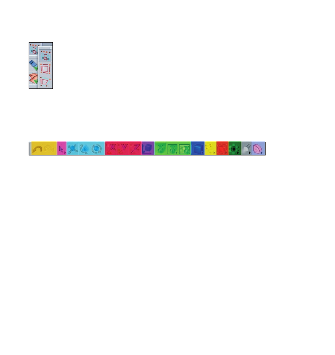
The image shows the left icon palette. At the very top you can see the previously mentioned
predened layouts. Below that we have the (green) “Make Object Editable” button. This function
lets a primitive be transformed using points, polygon or edges. The editability of a primitives is
limited until it is transformed! You can determine size and number of segments but you cannot
make any polygonal transformations. Next we have the “Use Model Tool” and “Use Object Axis
Tool” (red icons). You can move, scale or rotate a selected object or rotate it around its own axis.
The next three (blue) icons represent the “Use Point Tool”, “Use Edge Tool” and “Use Polygon
Tool”. In each of these modes you can either move, scale or rotate an object’s points, edges or
polygons or edit the object with CINEMA 4D’s integrated tools. The next (purple) icon lets you
choose between point, edge or polygon selection.
Page 15
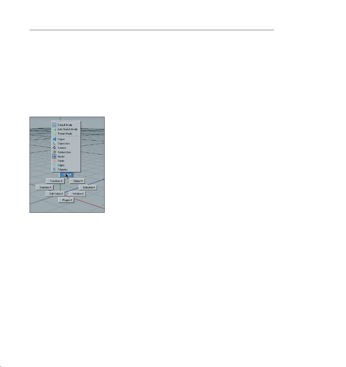
You select your points, edges or polygons in “Default Mode” by simply activating the
corresponding points, edges or polygons. In the “Auto Switch Mode“ CINEMA 4D recognizes
whether your cursor is over a point, edge or polygon. A click of the left mouse button selects the
correct mode automatically. The “Tweak Mode“ lets you do the same with an active move, scale
or rotate tool. Now you know the most important functions of the icon palette.
Now we will turn our attention to the most used icons on the top palette.
On the left you will nd the “Undo/Redo“ arrows (orange). This lets you reverse or repeat each
step. You can determine how many steps CINEMA 4D lets you undo by changing the presets in
the main menu (edit/preferences/document).
Next to the Undo/Redo icons you will see the (pink) “Live Selection“ tool. This lets you select
your points, edges or polygons for editing. The next three (turquoise) icons are pretty much selfexplanatory. Use these to move, scale or rotate your object or your object’s selected points, edges
or polygons. When rotating, please note that the center of the rotation will always be that of the
active object (or camera).
The following three (red) icons let you lock/unlock the X, Y or Z Axis. These settings let you
determine the direction in which your object will be edited. If only one of these icons has been
activated it will only be possible to move the object in that particular direction, unless you are
using the object axis arrows, which are always independent of the locked/unlocked X, Y or Z
directions.
The next (purple) function lets you switch between the “Use World/Object Coordinate
System“. Let’s assume the object axis of your wonderfully modeled head is slanted (whereas the
term “wonderfully modeled“ is open to interpretation in this case ;o). If you lock the X and Y axis,
make the head active and move it, you will notice that your model is moving in the X-direction of
the object axis.
7CINEMA 4D R9 Quickstart – Interface
Page 16
8 CINEMA 4D R9 Quickstart – Interface
9CINEMA 4D R9 Quickstart – Interface
Now select the world-coordinates instead and see how the object moves on the X axis parallel to
the world coordinate system.
This function can be very useful in modeling or animating your scene.
Now to the next group of three, the (red) Render Icons. The rst function (Render Active View),
with a vase as a symbol, renders the image in the editor view. The rendering will be made using
the settings you have specied, with exception of image size and several post effects. Icon
number 2 renders the image in the “picture viewer” using the settings you have specied in icon
number 3’s “Render Settings”. You can also render animations in the picture viewer since the
function “Render Active View” (as the name states) is only meant for checking the scene in the
active view.
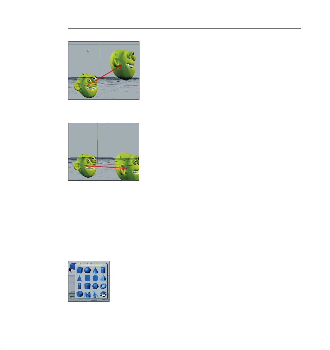
The next symbol is the (blue) group window “Add Cube Object“. It contains all of CINEMA 4D’s
available predened parametric objects.
Page 17
9CINEMA 4D R9 Quickstart – Interface
One click and the world’s most used object is created – the cube. Click and hold to see all
available parametric objects. This is where you choose the initial shape you will need. And don’t
forget! “Only parametric objects that have been converted to polygon objects can be edited at a
polygon, point or edges level!“
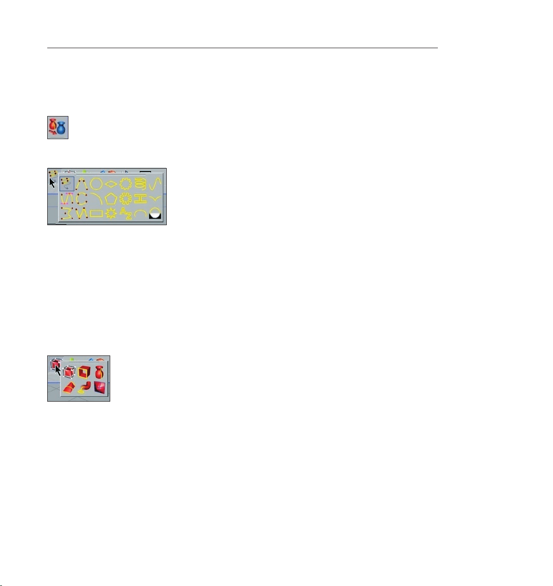
The yellow icon represents spline objects.
The term “spline“ has its origin in ship building. The wooden slats which were elastic enough to
conform to the shape of the ships hull were called splines. In the 3D world splines can be dened
as “point based curves“. A spline “follows” several previously dened points while still retaining
a curved form. This group window offers several tools for drawing splines, as well as predened
shapes from which to choose. A spline can act as a path for a camera to move along. Just draw a
spline and let the camera move along its path. Splines can also be used to model. To put it simply,
splines are placed in a row as a wire frame over which a skin is stretched using “Loft NURBS“, for
example.
The next (dark orange) group icon hosts probably the most important CINEMA 4D object, the
“HyperNURBS object“.
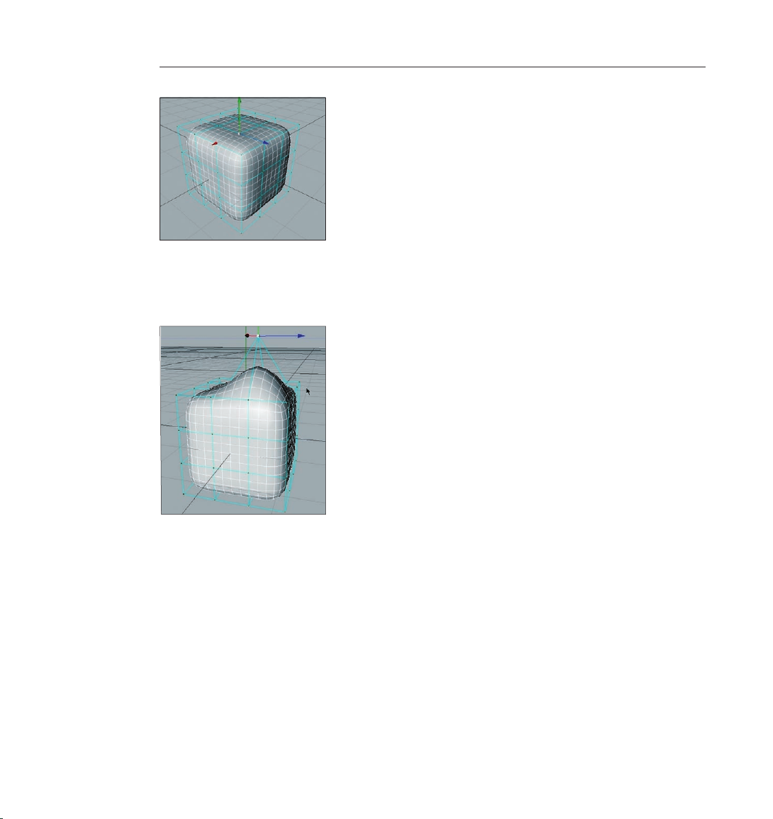
If a polygon object is a sub-object of a HyperNURBS object its polygon wire frame (mesh) will be
subdivided to a higher degree. Visually it will be comprised of many more smaller polygons than
before the subdivision (the object automatically looks softer/rounder) without losing the original
mesh. As you can see in the next screen shot: The outer mesh (turquoise) shows the polygon
cube’s actual subdivision. The ner inner mesh (white) shows the subdivision of the HyperNURBS
object.
Page 18
10 CINEMA 4D R9 Quickstart – Interface
11CINEMA 4D R9 Quickstart – Interface
The advantages, especially in modeling, are obvious. Since the object contains few points (edges/
polygons) that can be edited it remains very managable. You can drag just one point of the
original wire frame and the HyperNURBS mesh, with its ner subdivision, will follow the point
being dragged (see next screenshot).
If the polygon object were made up of such ne subdivision modeling, it would be much
more complicated. You would pull one point and only one point would be moved. All other
surrounding points would retain their position. You would have to move each one by hand in
order to achieve the desired shape. Haven’t quite understood? No problem, in part 2 of our
Quick Tutorial you will try modeling like this yourself so you can learn the functions rst-hand. Of
course this group window contains several NURBS objects, of which you have already gotten to
know the loft and HyperNURBS.
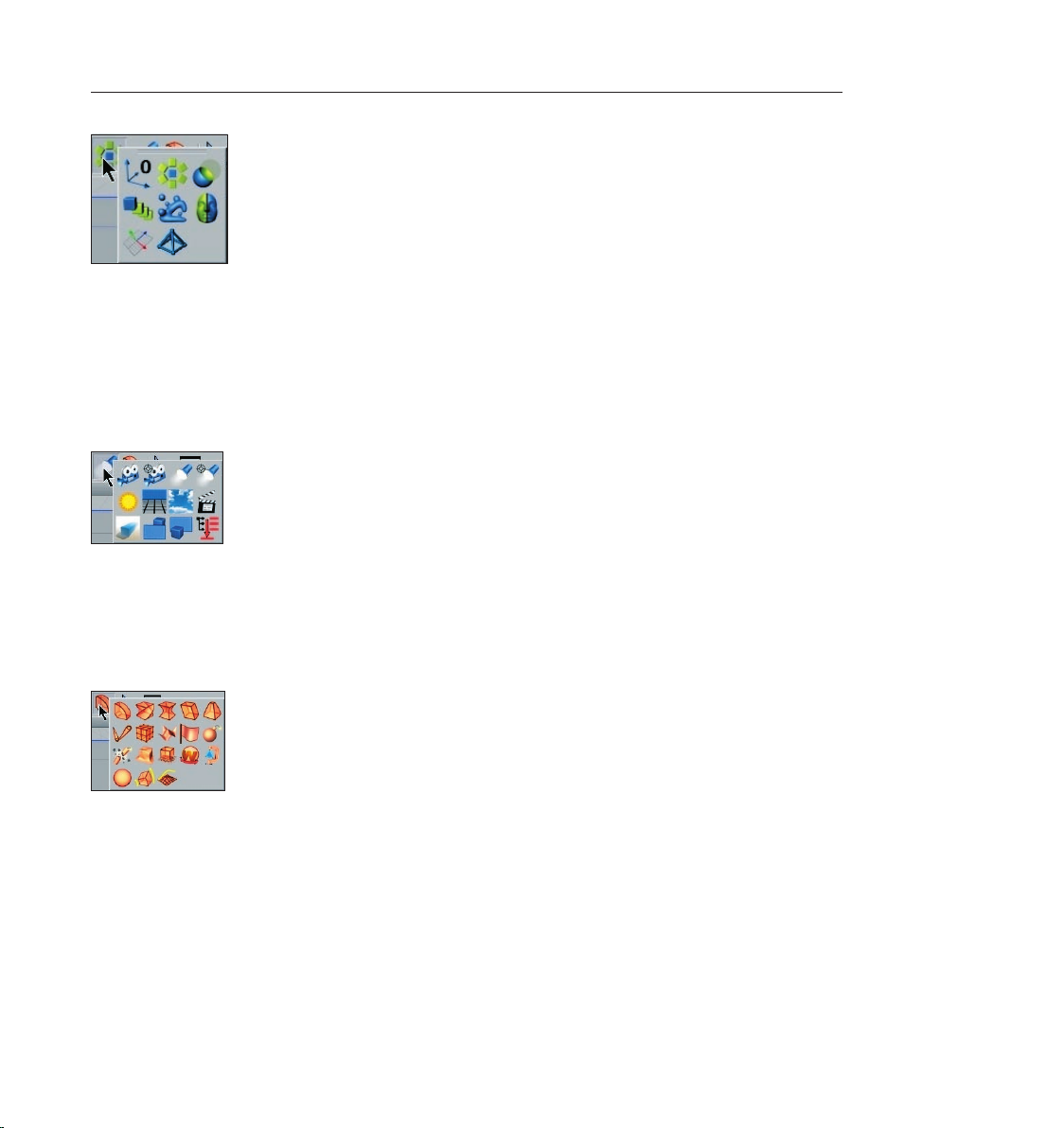
Let’s take a look at the objects behind the (green) “Function Objects“.
Page 19
11CINEMA 4D R9 Quickstart – Interface
Here you will nd, for example, the null object (object without geometry), the boolean object
for boolean operations (parametric and polygon objects can cut/slice each other), as well as the
symmetry object, which can be unbelievably helpful in character modeling. You simply model one
half of the gure and use the symmetry object function to mirror it to create the other half of
the gure.
The second-to-last icon contains at least one object without which the best model would appear
inconspicuous and at: the light (black & white).
The proper lighting of a scene is at least as important as the scene itself. You can make a better
impression with simple models and great lighting than you can with a fantastic model lit by a
default light. We’ll go more into detail about that later. Here you will nd camera objects, the sun
object and the environment object among others (adds a general color and / or fog to the scene).
The “Deformers“ can be applied with the objects of the last icon (light blue).
Use these to bend, deform or squash objects for modeling or animation. There are several helpful
tools in this group window. After you have worked your way through this tutorial you can try
some of these yourself. You can deduce what most of them do by their names (which appear at
the lower left of your monitor when you place the cursor over each icon).
Page 20
12 CINEMA 4D R9 Quickstart – Interface
13CINEMA 4D R9 Quickstart – Interface
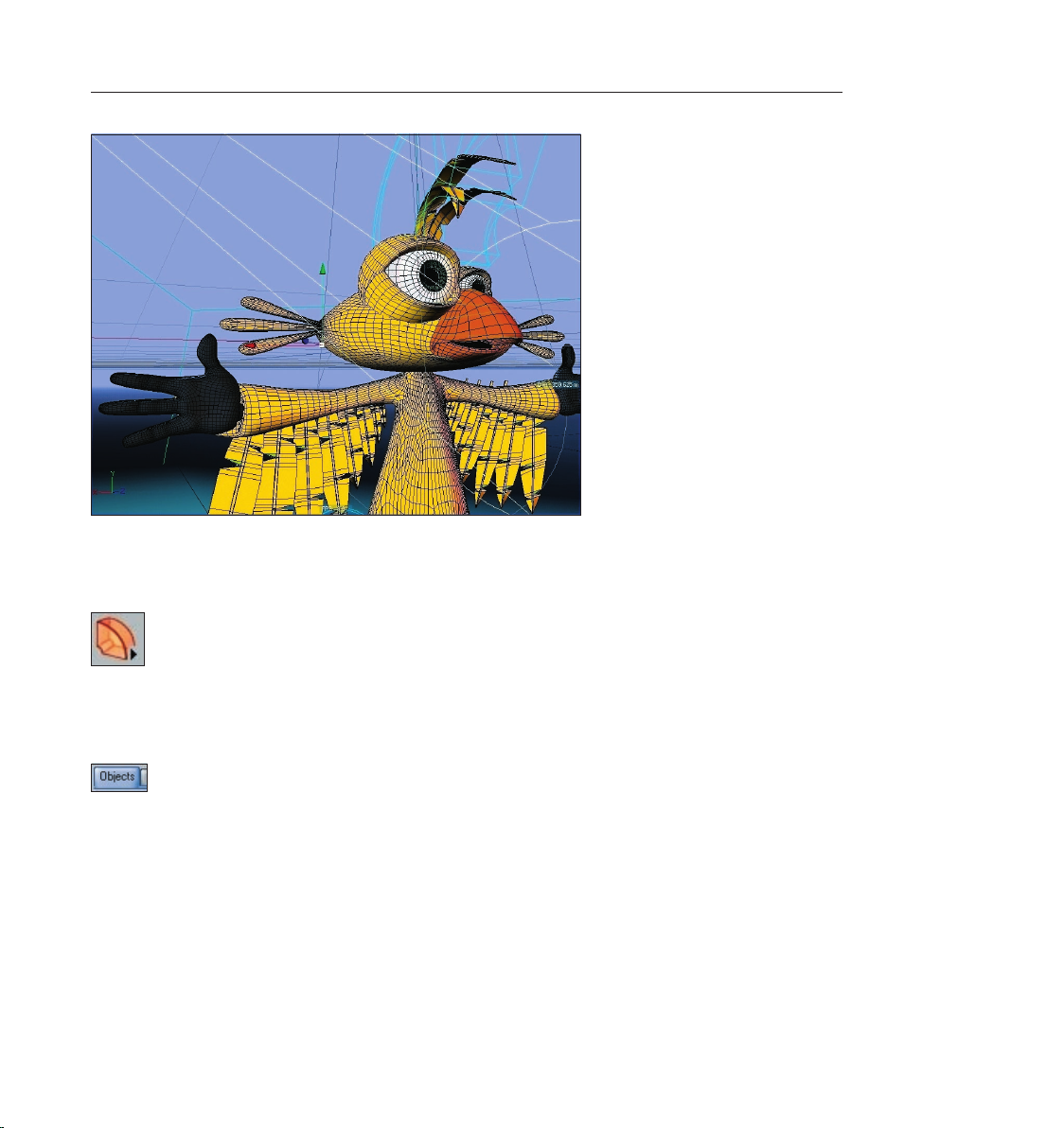
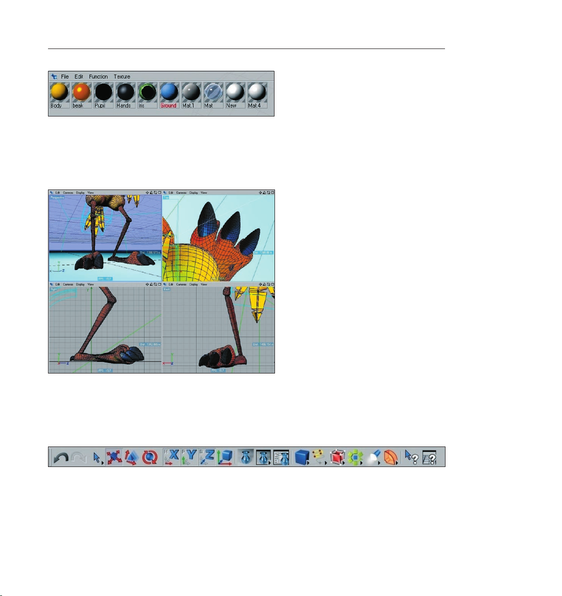
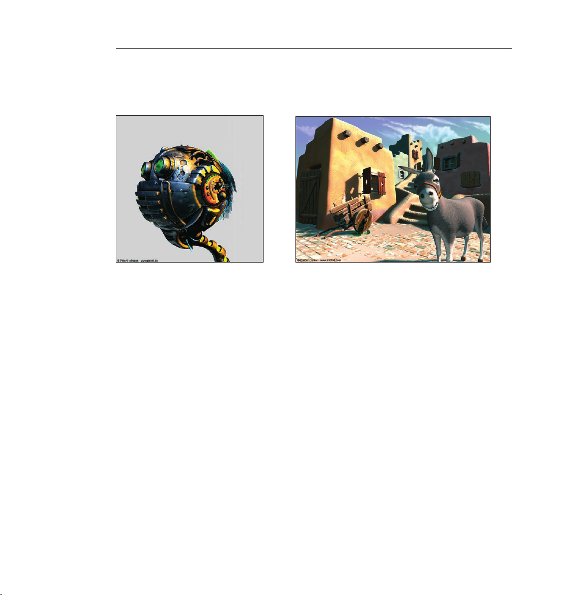
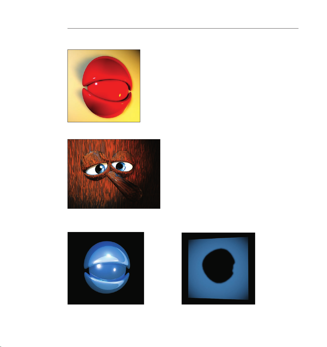
3. Sample Images
This is where we could use a little fanfare. Think about it and let these images inspire you a little
before we move on to the hands-on part of this tutorial.
Page 21

13CINEMA 4D R9 Quickstart – Interface
Page 22
14 CINEMA 4D R9 Quickstart – Arranging
15CINEMA 4D R9 Quickstart – Arranging
4. Quick Tutorial – Arranging Objects
In order to give you a feeling of how CINEMA 4D works we will begin with the simple creation of
a couple of basic objects.
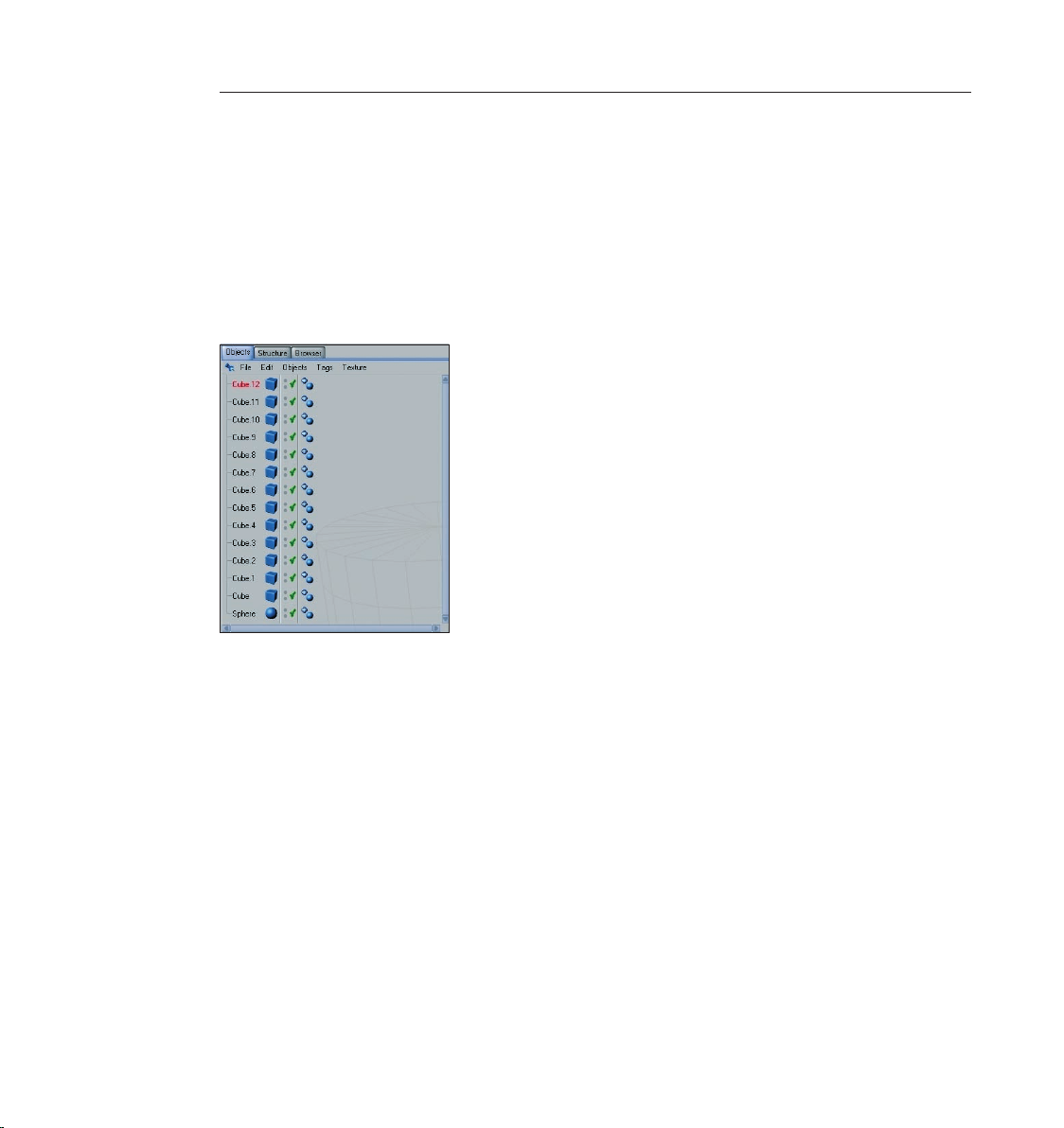
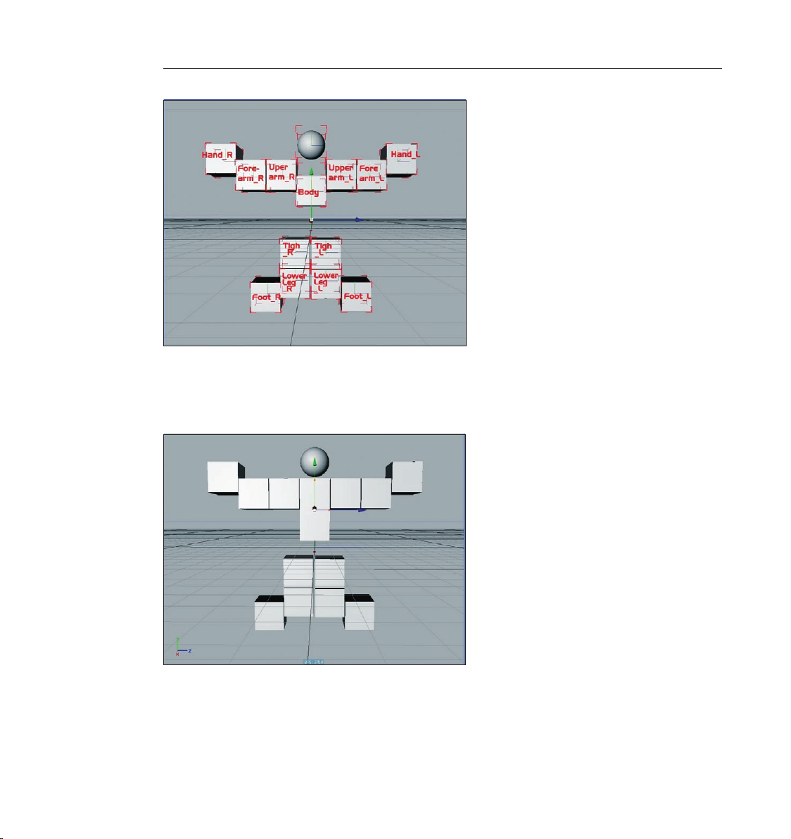
Create 13 cubes and one sphere using the main menu (objects/primitive/cube/sphere) or the
group icon “Add Cube Object“.
“13 cubes“ may give you the impression that we are preparing to create a mammoth project
but don’t worry, we are going to arrange the cubes into a little gure. When you’ve created the
cubes you can see their alignment in the Object Manager at the right.
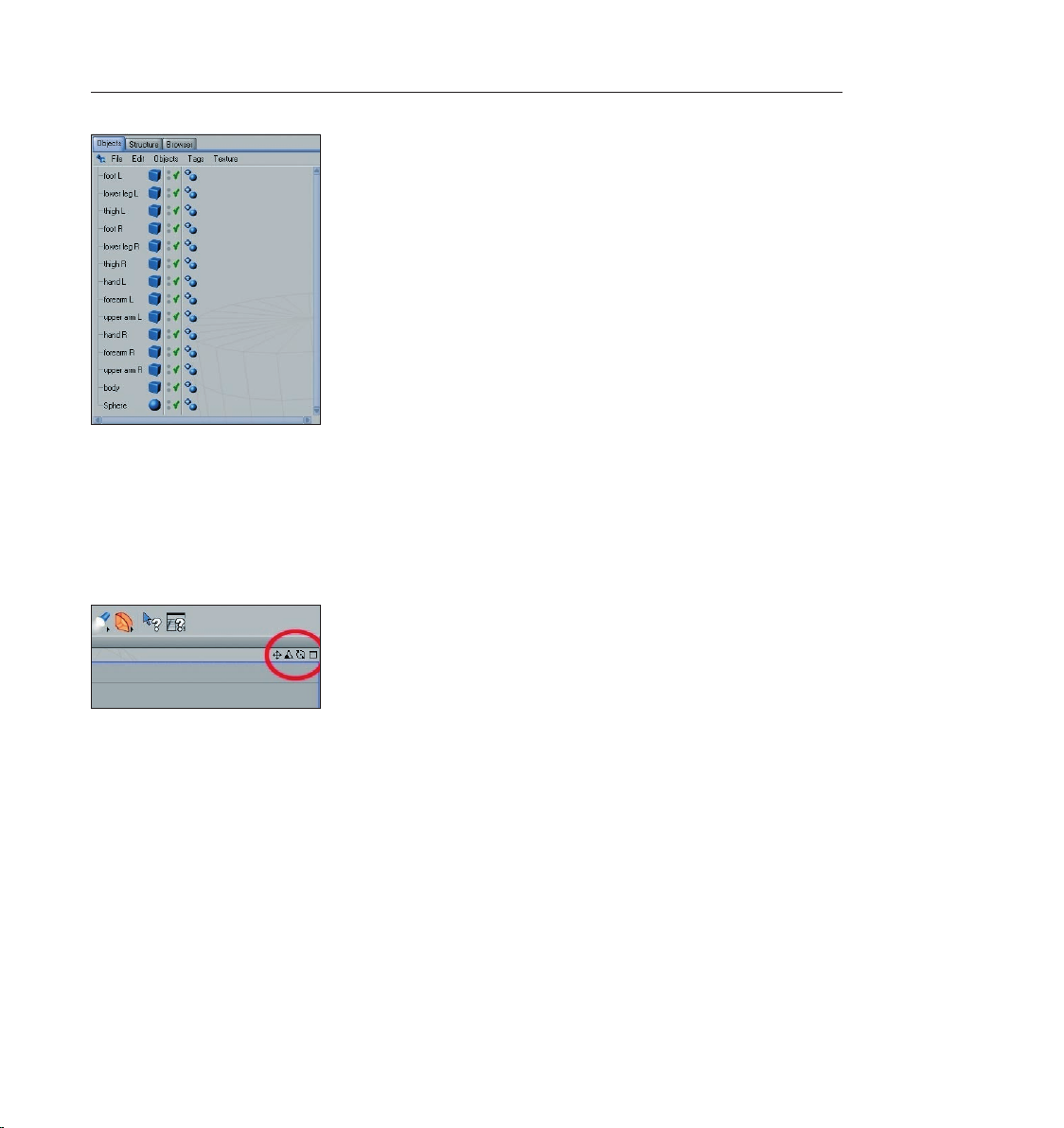
For better reference, give each cube a unique name (double click the current object name in the
Object Manager to open the context window for renaming the object). You can simply refer to
the next screenshot.
Page 23
15CINEMA 4D R9 Quickstart – Arranging
As you can see in the editor window, only one cube is visible. That’s because all cubes are located
at the same coordinates and are the same size with the sphere in the center. Of course we will
want to change this state now. But rst a quick introduction to navigating the editor window.
How do I rotate and move my point of view? Simple. Take a glance at the top right corner of the
editor window. Here you will nd four small symbols with which you can change your point of
view (of course we mean the point of view of the editor window, not your personal point of view.
We can have little inuence on the latter.)
The rst symbol (click – hold – move mouse) moves the view. The second symbol (triangle) lets
you zoom in and out and the third (circle) lets you rotate the scene. Selecting the little rectangle
to the right will divide the entire viewport into four views, giving you a better overall view of
the scene. Each of the four views has its own little rectangle which, when clicked, enlarges the
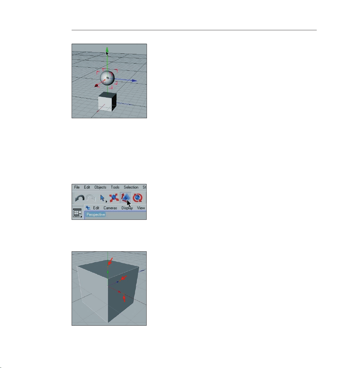
respective window. Zoom out a little and select the object “Head“ in the Object Manager. The
head‘s axis will be visible in the editor window. Drag the head‘s green object axis to a point over
the cubes.
Page 24
16 CINEMA 4D R9 Quickstart – Arranging
17CINEMA 4D R9 Quickstart – Arranging
Each of the axis‘ arrows can be selected and dragged in its respective direction. This prevents the
object from being dragged in the wrong direction in the editor view (as opposed to clicking on
the object itself and dragging it). It is often impossible to see in which direction an object is being
dragged in a 3D view. A similar method of moving an object in a single direction is the previously
mentioned locking of a specic axis in the command palette. This prevents an object from being
moved in the direction of an axis that has been locked unless you click and drag one of the
object’s own axis arrows. If no axis are locked, click on the “Scale“ tool on the icon palette at the
top.
The ends of the axis‘ arrows have changed form arrows to boxes. Dragging these boxes will scale
the object along that particular axis. Parametric objects (not converted polygon objects) will
display little orange handles.
Page 25
17CINEMA 4D R9 Quickstart – Arranging
They make it possible to stretch and squash the parametric object on the respective axis
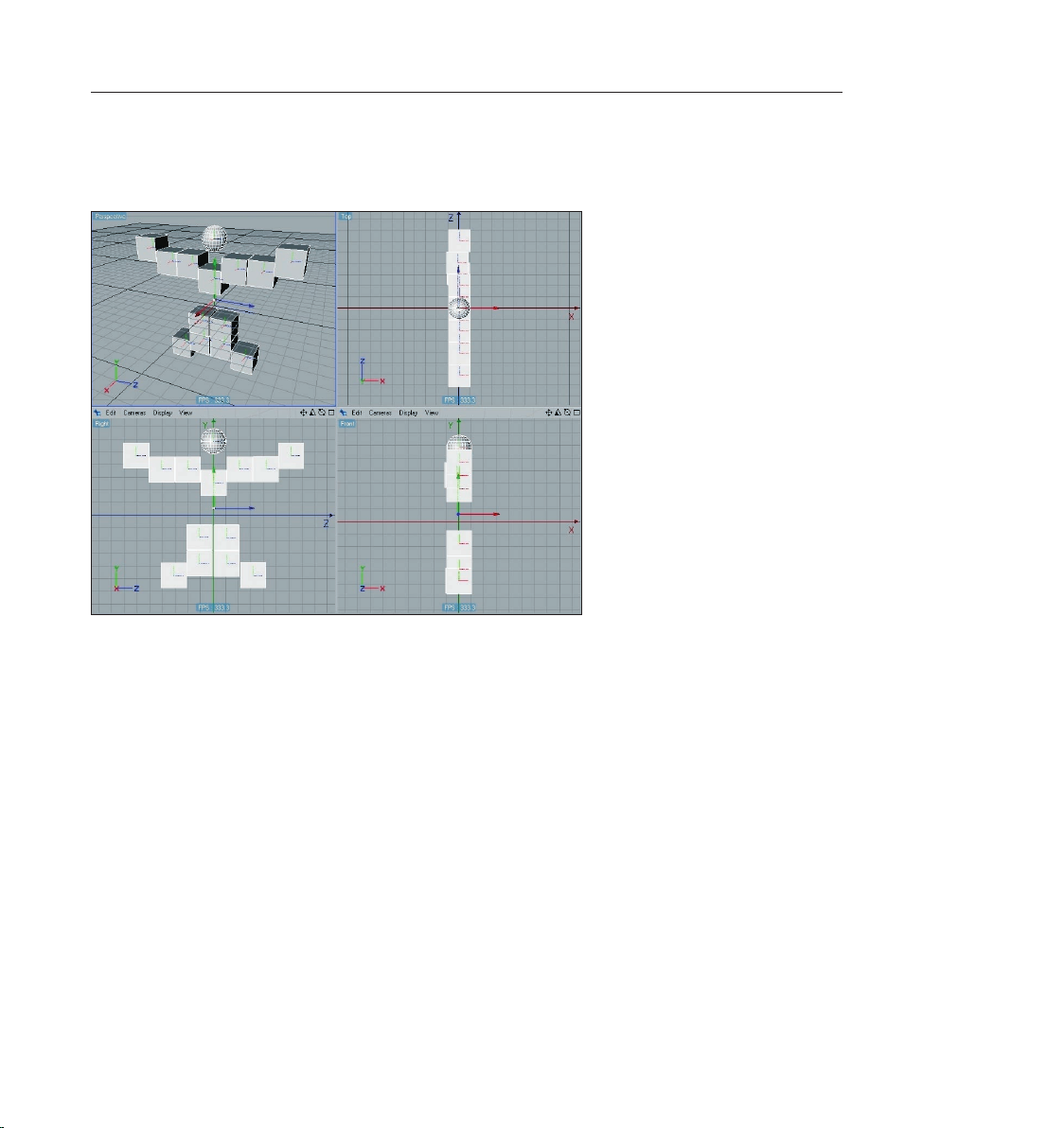
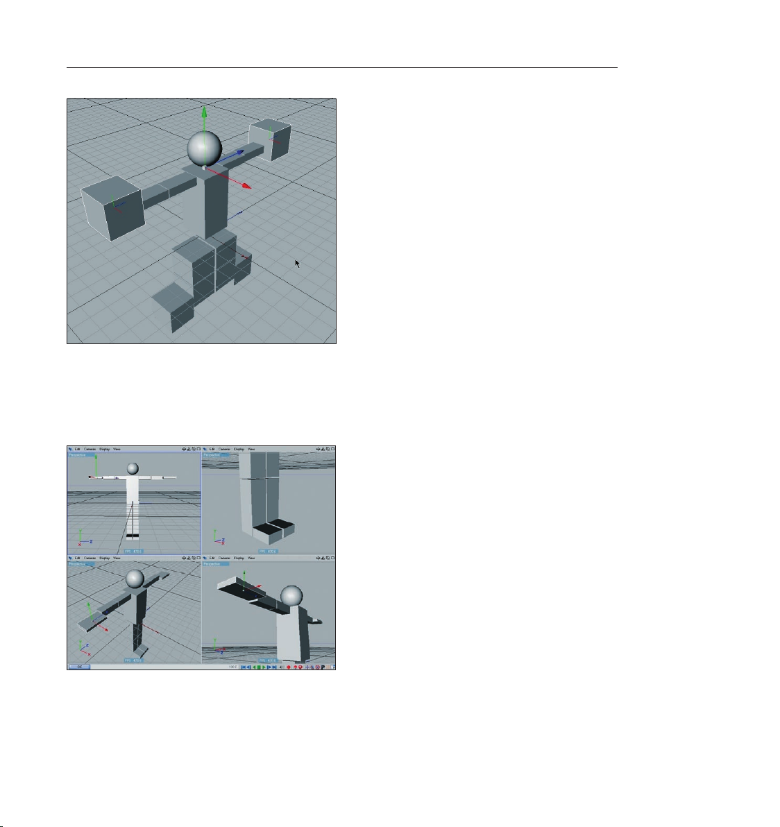
Now we’ll get to the nitty gritty part of this project. You now have enough basic knowledge to be
able to arrange the objects according to the following screenshots.
If you prefer, you can switch to a four viewport mode (click the little rectangle at the top right of
the editor window). If the objects are displayed as wire frame objects you can switch to “Quick
Shading“ or “Gouraud Shading“ under “View“ in the editor’s menu. Now let’s get to work. Here’s
a screenshot of the gure from the front for reference.
Page 26
18 CINEMA 4D R9 Quickstart – Arranging
19CINEMA 4D R9 Quickstart – Arranging
After you have arranged the cubes it still looks nothing like a “human character“. We have to
rotate and stretch the gure a little. Click on “Figure“ in the Object Manager and select the
orange handle on the (green) Y axis. Drag this handle until the top edge of the cube lies even
with the arms.
Using the orange handles, select the cubes that make up the arms and adjust their size and
position as shown in the next screenshots.
Page 27
19CINEMA 4D R9 Quickstart – Arranging
If you want to scale all cubes of the arms at once you can do this as follows: with the shift button
pressed, select the objects “Lowerarm_L“, Upperarm_R“, Lowerarm_R“ and “Upperarm_R“ and
press “C“ on you keyboard to proceed with the “Scale“ function in the Y and X axis. As you can
see, the orange handles are not visible. Squash and move the gures arms and legs until it looks
like the following image.
This should be no problem with the knowledge you have gained up to this point. To squash the
legs, for example, you can squash several objects at once instead of each one individually (as was
the case with the arms).
Page 28
20 CINEMA 4D R9 Quickstart – Modeling
21CINEMA 4D R9 Quickstart – Modeling
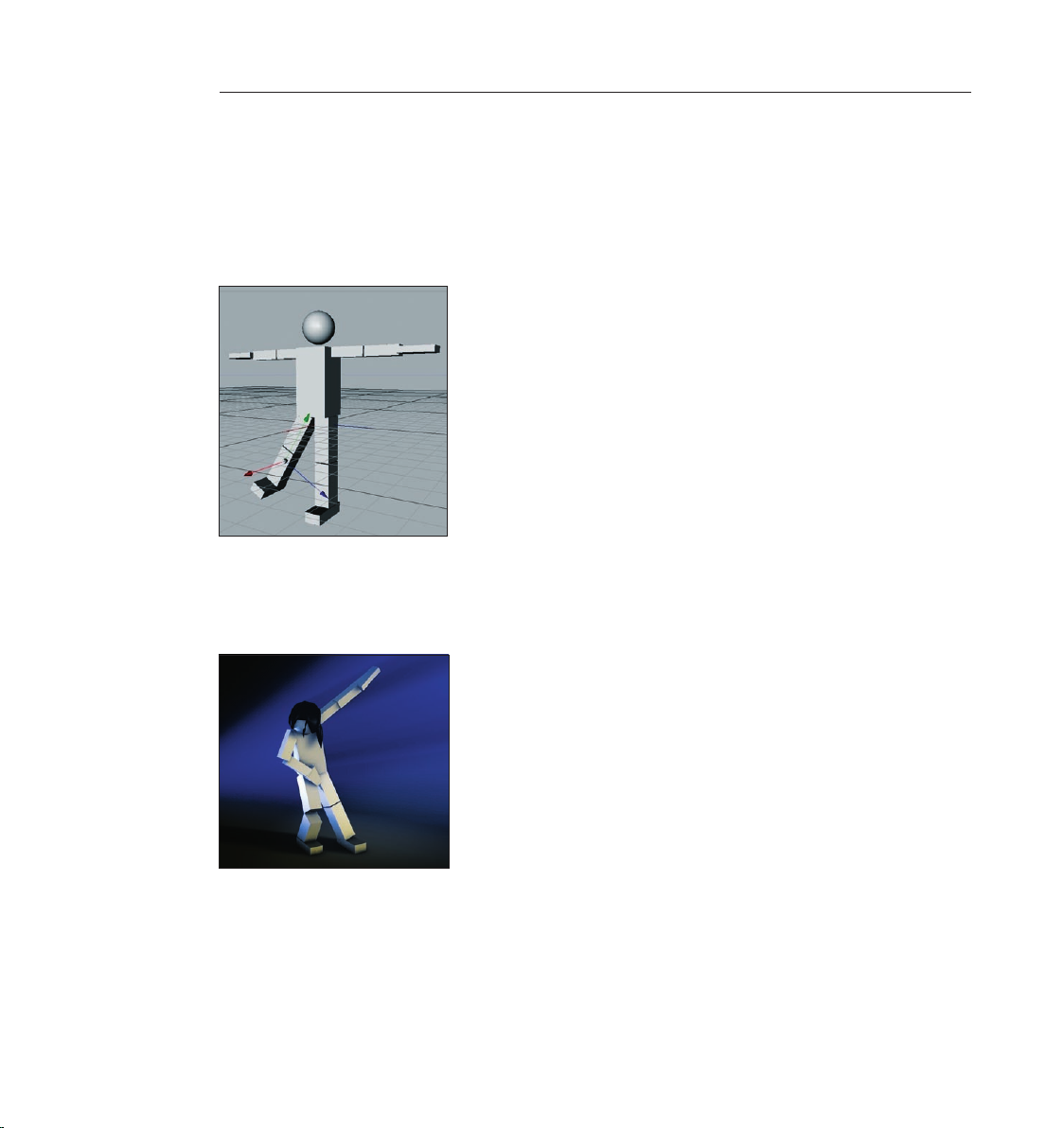
When you’re nished select the objects “Upperleg_R“, “Lowerleg_R“ and “Foot_R“. Once they
are highlighted in red in the Object Manager press the “G“ key on your keyboard. This groups all
makes all selected objects children of a Null object. If you look at the Object Manager you will see
the newly created Null object. Clicking on the “+“ symbol will open the hierarchy and the objects
we just selected will be shown. When the Null object is selected, the axis of this Null object serves
as the axis for all three leg objects. If this axis is rotated all children of this Null object will be
rotated. Move and rotate the Null object a little and you can make the gure stick its leg out.
After you have selected the “Rotate“ function you can select the axis rings of the rotation sphere
and rotate the object into position. Try changing the gure’s position by using these different
“moving“ functions. If necessary, group objects into a Null object or select several objects at once
in order to bring them into position.
Page 29
5. Quick Tutorial – Modeling
This is the most important part of this tutorial: How is a model built?
There have been several new tools added to CINEMA 4D’s release 9 that will make modeling
easier and improve your workow quite a bit. For example the knife tool has received a general
overhaul and now offers as one of its new knife tool functions the “Loop“ which makes it
possible to make a circular cut around the object. The new “Close Polygon Hole“ function is also
very helpful. It recognizes a hole in a mesh automatically and lls it without assigning points. An
additional new feature for quick navigation is the “General Popup“ which you can activate by
pressing “V“ on your keyboard.
21CINEMA 4D R9 Quickstart – Modeling
A circular menu lets you choose from several menus in which sub-menus appear when the cursor
is placed over them. Play with the menu a little and nd out how it can improve your workow.
In order to show you the basic functions and the most common way to work with the modeler
we will create an eye for a comic character.
Let’s start with the creation of a cube, which happens to be the most-used primitive for modeling
(Objects/Primitive/Cube). Press the “C“ key on your keyboard. By doing this you have just
converted the parametric to a polygon object. Most commands can be reached via so-called “hot
keys“ which, when used heavily, can speed up your work in CINEMA 4D quite a bit.
Switch to the “Use Polygon Tool“ mode (on the command palette on the left) and select the
“Live Selection“ tool (upper command palette). Make sure that “Only Select Visible Elements“
is active in the Attributes Manager. Mark the cube’s top polygon which will turn yellow when
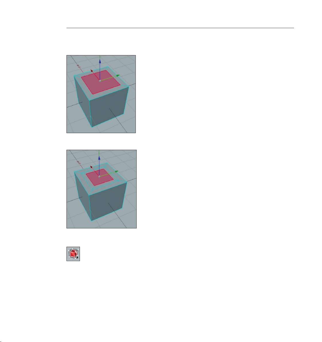
you place the cursor over it and turn red when you have selected it. Click on this polygon with
the right mouse button. Choose “Extrude Inner“ from the menu that appears (hot key “I“). Click
with the left mouse button on the top red polygon, hold the left mouse button pressed and drag
Page 30
22 CINEMA 4D R9 Quickstart – Modeling
23CINEMA 4D R9 Quickstart – Modeling
the mouse a little to the left. A second square should have been created, as seen on the next
screenshot.
Repeat this procedure to create another square on the top of the cube.
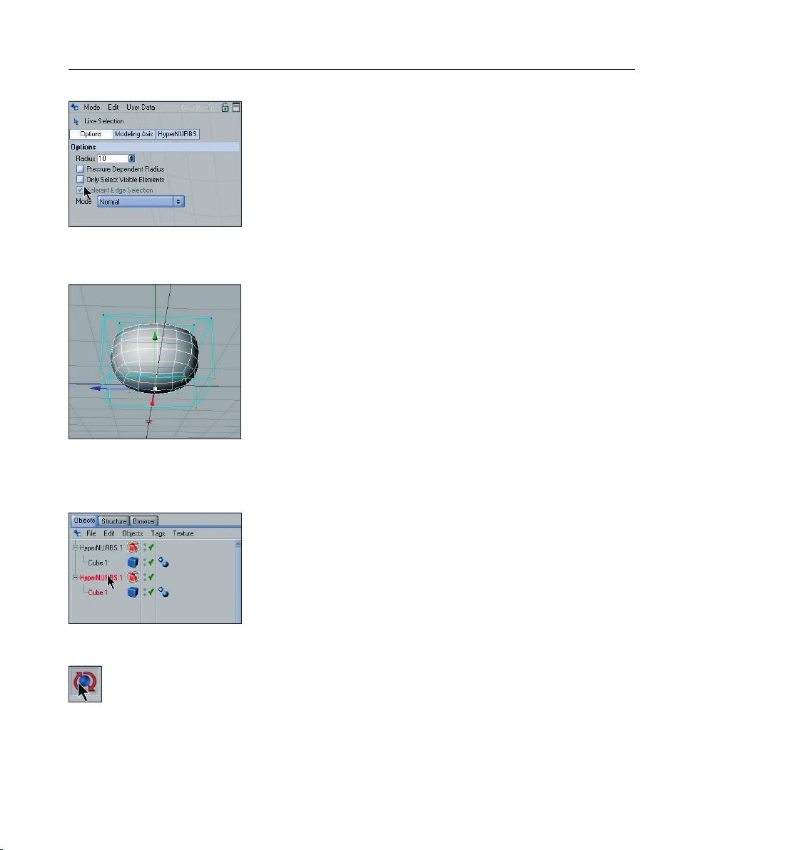
Create a HyperNURBS object using the top command palette
and make the cube a sub-object of the HyperNURBS object. This will serve to subdivide our
polygon object without us having to subdivide the original mesh. (Select the cube in the Object
Manager and drag it onto the HyperNURBS object and let go when the little arrow points down.)
Your cube will now look like this:
Page 31

23CINEMA 4D R9 Quickstart – Modeling
Grab the blues Z-axis in the editor window and drag it down until a relative large indentation has
been made.
Rotate your view until you have a good view of the underside of the cube and switch to the “Use
Point Tool“ mode. Now, using the “Live Selection“ tool, select all four points on the underside,
Page 32

24 CINEMA 4D R9 Quickstart – Modeling
25CINEMA 4D R9 Quickstart – Modeling
switch to the side view and drag these four points using the green Y-axis – drag them until the
four inner points of the indentation can be seen.
If you created the indentation deep enough you may have already been able to see these four
inner points. (In the next screenshot you can see an X-ray view of the cube in which you can see
the hidden points very well. More on “X-ray“ at the end of this chapter).
We want to round off the shape a little more and to do that we will select the inner points. Even
though they are visible you won’t be able to select them with the “Live Selection“ tool. This is
due to the fact that “Only Select Visible Elements“ in the “Options“ menu of the “Live Selection“
tool in the Attributes Manager is active. Deactivate this option and try the selection again. Now
it’s possible to select the points. But careful! If you forget to turn this option off you might select
all the points in the front of the object and accidentally select all points at the backside of the
object as well. The surface on the backside will be altered and you won’t notice until you rotate
the object at a later point. So always be aware of this option in the Attributes Manager!
Page 33
25CINEMA 4D R9 Quickstart – Modeling
Once you have selected all eight points on the object’s underside drag them along the green Yaxis a little to the top to give the object a rounder look.
Click on the HyperNURBS object in the Object Manager and drag it down a bit while
pressing the “Ctrl“ button on your keyboard. We have now duplicated the hemisphere. The same
object is now visible in the Object Manager twice.
Now select one of the HyperNURBS objects and select the “Rotate“ tool.
You can now adjust the object’s angle by using the “Rotation Rings“ on the “Rotation Ball“. Drag
the blue Z-axis ring down 150 degrees.
Page 34

26 CINEMA 4D R9 Quickstart – Modeling
27CINEMA 4D R9 Quickstart – Modeling
Repeat this step for the other HyperNURBS object but only to 50 degrees.
Position both hemispheres as pictured below using the “Move“ function:
Page 35

Here you can use the aforementioned locking of the axis function and switch to using the world/
object coordinate system.
27CINEMA 4D R9 Quickstart – Modeling
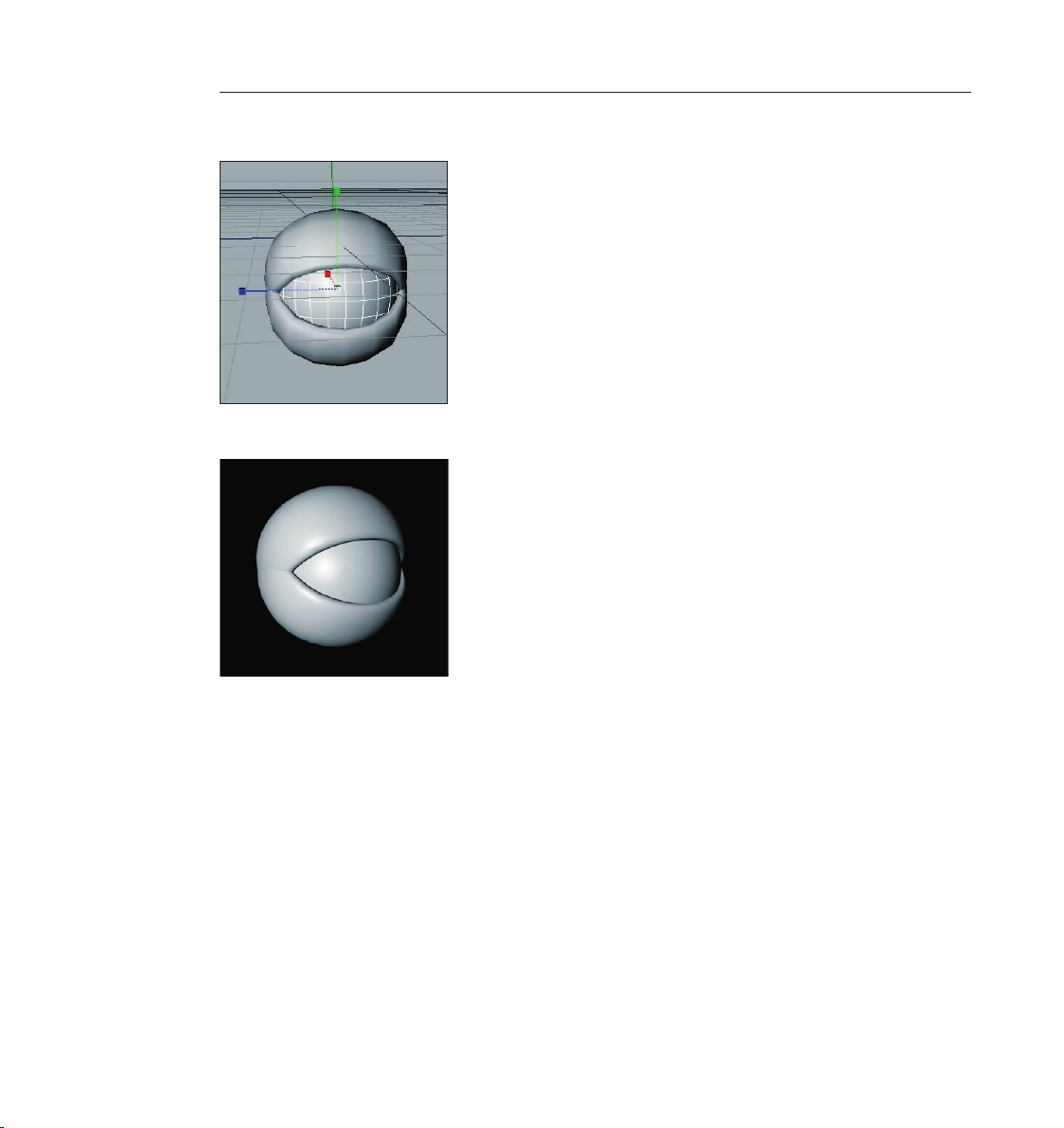
Now create a sphere and move it into a position almost completely covering both our
hemispheres.
Page 36
28 CINEMA 4D R9 Quickstart – Modeling 29CINEMA 4D R9 Quickstart – Materials
Using the “Scale“ function you can resize the sphere to t inside our two hemispheres.
Congratulations! You have just created your rst modeled object.
You can increase the HyperNURBS object’s subdivision to give our model a smoother look. Simply
select the respective HyperNURBS object you want to smooth and set the “Subdivision Editor“ in
the Attributes Manager’s “Object“ menu to a higher value. The parameter “Subdivision Renderer“
is only responsible for renderings in the picture viewer.
Our eye still looks a little blind. We’ll change this in the next chapter by adding a pupil texture.
Before we do that, though, we’d like to give you some more modeling tips.
Adjust the inuence of HyperNURBS: Select both cubes and several polygons in the Object
Manager. Press the “V“ key on your keyboard, select the menu “Structure“ and click on the
“Weight HyperNURBS“. If you now click anywhere in the editor window with the left mouse
button and drag the mouse to the right you can determine the strength of the HyperNURBS for
the selected polygons. If you are not satised with the result and have unclean edges try this
function in the “Use Edge Tool“ mode. This will give you better results.
If you should want to select points that lie within an object or if you have “Only Select Visible
Elements“ deactivated and want to avoid accidentally selecting points on the backside of the
Page 37

object simply activate “Use X-ray“. You will nd this function under display/use x-ray. This lets you
see through the object and see every point (Polygon/Edge). Accidental selection of hidden points
is thus not possible and you have an excellent overview of the inner points of the object which
would normally not be visible from the outside.
6. Quick Tutorial – Materials
A well-modeled object can make a mediocre impression if the right textures aren’t used. Textures
give a model color, highlights, structure and other important surface properties. A texture placed
into the bump channel, for example, gives the object’s surface an uneven, bumpy look. This
effect can be used to imitate skin wrinkles, scars or the surface of an orange. Using the luminance
channel you can give an object’s surface a self-illuminating property or integrate a SSS effect
(sub-surface scattering) which lends the surface a slight translucent / reective look, like human
skin or candle wax, for example. In short: Textures have the same signicance as the outer shape
of an object because they are necessary for achieving the desired atmosphere, coloring and
surface structure.
We will begin with a brief introduction to the individual material channels:
Color: This is where the material’s color or the base color for the texture is set.
Diffusion: This channel makes your texture “irregular“. Through the application of a noise shader
or a texture your object receives a dirty or dusty look. If desired it can also inuence the specular,
reection and luminance channels respectively.
Luminance: The material is given an illuminative property which is also taken into account in the
radiosity calculation.
Transparency: This is where you determine the material’s opacity.
Reection: Gives the material a reective characteristics.
Environment: A material is used to simulate an environment reection.
Fog: This channel lets you apply a fog or cloud property to a material.
Bump: Translates light and dark elements of a texture or a shader to simulate the height and
depth of an uneven surface. Scars, wrinkles or scratches can be simulated using this channel.
Alpha: A texture’s transparency is determined by a material’s light and dark areas. Black equals a
transparency of 100% and white makes it opaque.
Specular: This determines a material’s specular properties.
Specular Color: This determines the color of the material’s specularity and can be inuenced by
a texture.
Glow: Gives the object a self-emitting glow.
Page 38
30 CINEMA 4D R9 Quickstart – Materials
31CINEMA 4D R9 Quickstart – Materials
Displacement: Deforms an object using light and dark values (calculates differences in height).
Do not confuse this with the relief channel which only imitates an uneven surface.
Since our eye still looks a little pale we will liven it up a little with the application of textures and
shaders. If you skipped the modeling chapter simply open the C4D_eye_Texture.c4d le. Now we
have the eye we created in the previous chapter. You can see in the Object Manager to the right
that the object does not yet have a texture applied to it. We will do something about that now.
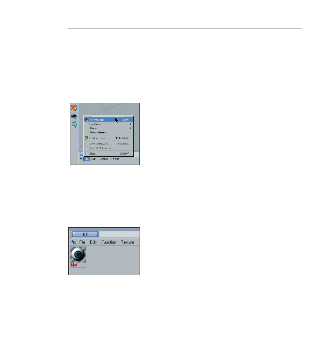
Click on le/new material in the Material Manager at the lower left.
A standard material has been created. If you click on this material its properties will be made
visible in the Attributes Manager to the right. In the “Basic“ menu you can determine which
channels should be activated for this material. Go ahead and activate the Bump channel. As soon
as you have done that a new menu button, “Bump“ will appear. Now click on the menu button
“Color“ load a texture into the material by clicking on the small arrow next to “Texture“. Choose
“Load Image“ and load Iristexture.jpg. In the mini-preview of the Material Manager at the lower
left of your screen you will see the texture displayed as soon as it has been loaded. This gives you
a good overview of the materials being used in the scene.
Repeat this procedure for the “Bump“ channel and load Iristexture_bump.jpg into the channel.
This JPEG contains the gray scale version of the iris texture which we need to create a relief effect
for the surface. You can also choose “Filter“ and load the color texture here and set its saturation
to 100%. This saves you from having to load a second image. The bright areas of the image
will later appear to be raised on the object and the dark areas of the image will appear to be
Page 39

31CINEMA 4D R9 Quickstart – Materials
somewhat indented. A true deformation of the object will only take place in the “Displacement“
channel. The “Bump“ channel does not alter the polygon’s surface but uses an optical illusion to
give the surface its structure.
Click on the material in the Material Manager with the left mouse button and drag it onto the
object eyeball in the Object Manager. (When you drag the material over the object you can let go
once the little black arrow points to the left).
You have probably noticed that the eyeball brightened somewhat after you applied the material
but you aren’t able to see the actual texture. We still have to change the offset properties and
the mapping size so the texture will be aligned properly on our object. At the moment the actual
image of the iris is lying distorted on the left side of the eyeball. You can check this by making
both HyperNURBS eyelid objects invisible for the editor. To do this click on the top gray dot to the
right of the object at the top of the Object Manager.
Click on the dot again and it will turn green, which makes the objects visible again independent
of the visibility settings of any parent object. The dot directly below has the same function except
that it affects the rendering.
Once you have made the eyelids invisible and have rotated the view a little the eyeball should
look as follows:
Page 40
32 CINEMA 4D R9 Quickstart – Materials
33CINEMA 4D R9 Quickstart – Materials
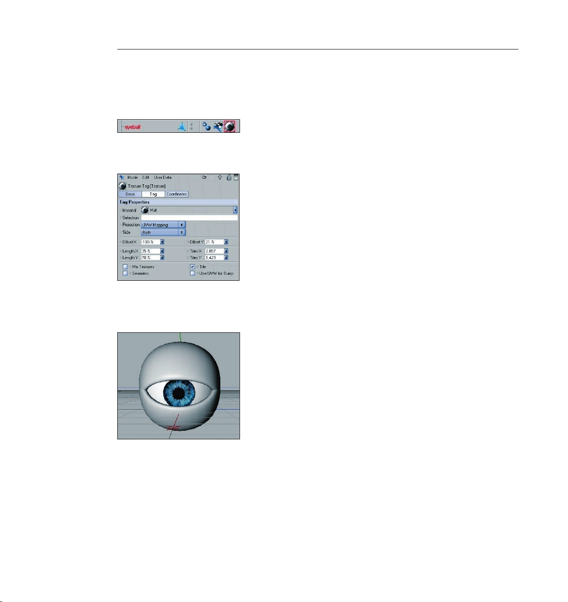
Switch the visibility of the HyperNURBS objects back by clicking again on the dots next to the
object in the Object Manager, making them gray. Click on the “Texture Tag“ at the right of the
Object Manager next to the object. It’s the material that we applied to the eyeball. You can
recognize it by the mini-preview of the texture in the Object Manager.
Once you have selected it you will see its parameters in the Attributes Manager. Adopt the
settings you see in the next screenshot:
We have just aligned the texture on the eyeball mesh by changing the “Length X“ and “Length
Y“ parameters. The offset setting put the texture in the correct position. If you rotate your view
again you will see that the iris texture is positioned correctly.
(Tip: If you want to undo an accidental change to the view just press “Ctrl+Shift+Z“). This
function is useful if you have inadvertently rotated the perspective view instead of the editor
view. You can also select edit/undo view in the main menu of the editor view.
Our eye may be able to look at us now but the eyelids still make it look a little too gray. We will
change a couple of settings that will give the eye a reptile look.
Create a new material (Material Manager/File/New material) and double click the new material.
This will open a dialog window for the material where we can make the necessary changes to
Page 41

33CINEMA 4D R9 Quickstart – Materials
this material. Click on “Color“ in the material channel and copy the settings of in the following
screenshot.
Click on “Color“ in the material channel and copy the settings in the following screenshot.
We will give the material a green tone and lower its brightness to 50%. Check the box next to the
“Bump“ channel. Click on the little black arrow next to the word “Texture“ and select the word
“Noise“.
Click on the button “Noise“ and on the following dialog page set the global and relative scales
each to 30%. This reduces the size of the bump-noise mapping which will result in a ner
depiction of the bump map.
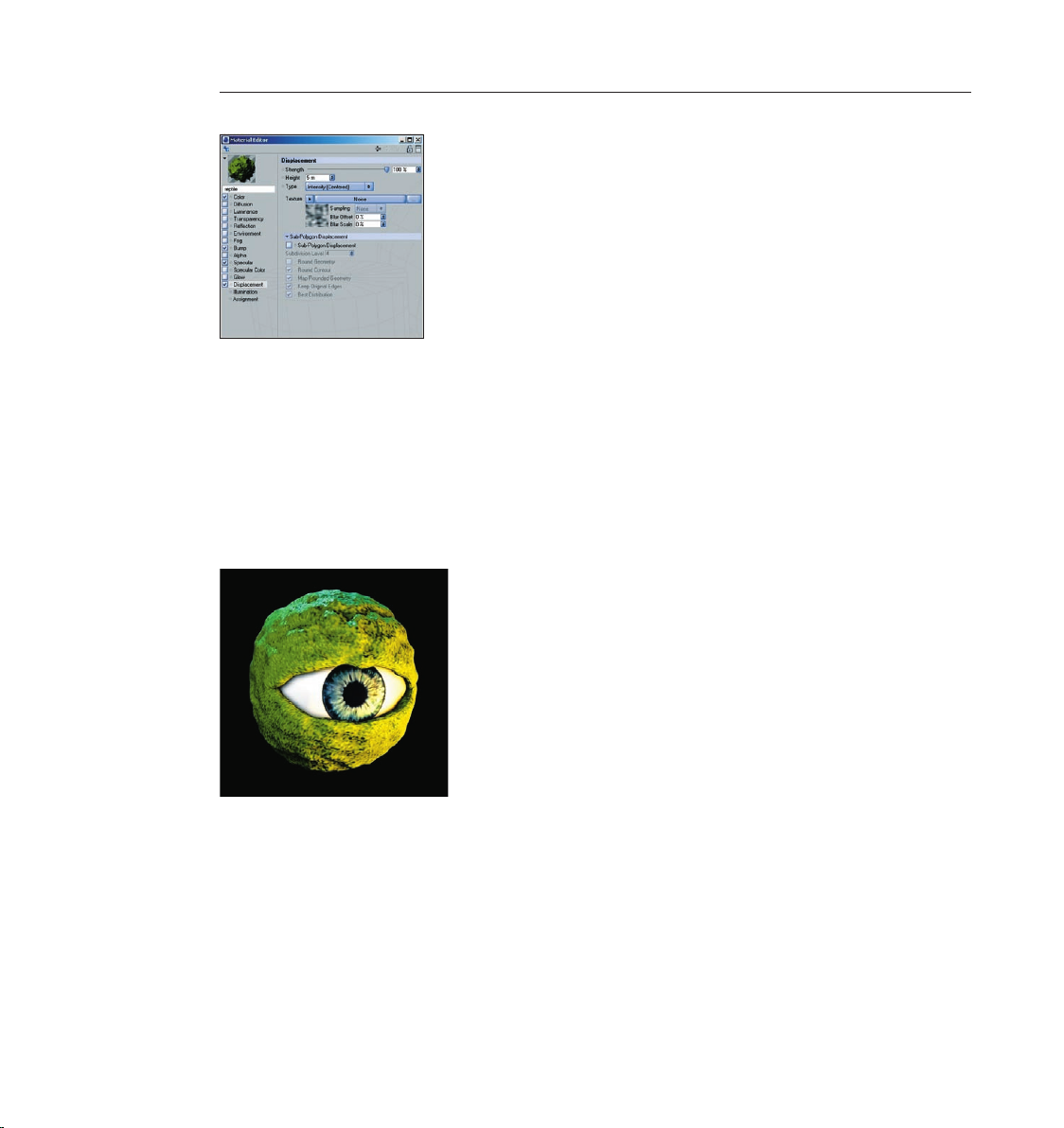
Check the box next to “Displacement“ and repeat the previously mentioned steps for the bump
channel but set the global and relative scales each to 150%. This will increase the size of this
channel. Click on the word “Displacement“ to return to the displacement channel’s main menu.
Page 42
34 CINEMA 4D R9 Quickstart – Materials
35CINEMA 4D R9 Quickstart – Materials
The displacement channel deforms the polygon mesh according to the bright and dark areas of
an image. Bright areas of the texture raise the polygon mesh and dark areas lower the mesh. This
lets you create a wide variety of shapes without having to model such a complex surface, thus
saving you a lot of time. The ornamental facade of a house or the relief of a sword handle are
good examples. The possibilities are endless.
Close the material editor window and set the HyperNURBS subdivision of the eyelids to at least 4
in the editor (Click on the respective HyperNURBS object and change the settings in the Attributes
Manager) and apply the new material to the eyelid objects. Render the view (Ctrl+R). The result
should be at least somewhat similar a reptile’s eye.
You have seen how you can get quick results without having to create a complex texture.
CINEMA 4D’s integrated shaders and channels offer so many possible variations that you will
never be able to try them all. Play around with some of the parameters, add a couple of channels
and nd out how they inuence your renderings.
Here are some more tips about channels for you to try:
Most objects in the real world are not as clean and immaculate as they might appear in
CINEMA 4D. Real stone gures show signs of weathering over the years and dirt has settled
in the wrinkles and cracks. You can simulate such “dirt“ very easily with CINEMA 4D by using
Page 43

35CINEMA 4D R9 Quickstart – Materials
the Dirtshader. The “Diffusion“ channel is ideal for this purpose. Just load the shader into the
diffusion channel of your chosen material (Effects/Dirt). Render the image and click on the “Dirt“
entry to apply your settings. The higher the “Number of Rays“ the ner the grain. The dirt shader
is not ideal for use in animations as a ickering noise may appear). For animations use the render
menu (Render/Calculate Dirt). Now the effect will be applied using calculated texture maps
(generators such as HyperNURBS objects will be turned off during the calculation. Only polygon
objects will be used in the calculation).
If you own the “Advanced Render“ module (or are testing the CINEMA 4D demo version) you
can render human skin, for example, very realistically. The shader Surface Scattering makes it
possible. By placing this shader in the luminance channel (effects/sub-surface scattering) the
effect is created when rays of light meet a slightly transparent object. Some rays inltrate the
object further and are dispersed, others are directly absorbed or bounce off. Further possible uses
for this effect would be for materials such as plastic, milk, candle wax or gurines made of jade.
You can load black & white textures into the alpha channel to inuence the material based on
the texture’s brightness, similar to the way you would use them for the bump or displacement
channels. The texture’s black areas would be rendered with a transparency of 100%. As
the texture becomes brighter the transparency is reduced accordingly. White would have a
transparency of 0%
If you choose “Shader“ instead of “New Material“ under “File“ in the Material Manager you will
see a list of bhodiNUT 3D shader presets. The advantage of these shaders is that you don’t
have to worry about mapping your texture or seams in your texture because a 3D shader will be
calculated for the 3D space. Here are a couple described in detail:
Cheen: Generates an electron microscope effect good for the depiction of bacteria or mites.
Page 44
36 CINEMA 4D R9 Quickstart – Materials 37CINEMA 4D R9 Quickstart – Lighting
Danel: Very good for simulating high-gloss nish
Banzi: Lets you depict various types of wood.
Banji: Calculates complex lighting situations with glass and even makes rear-projection (shadow
casting) on partially transparent materials such as rice or canvas paper possible.
Page 45
7. Quick Tutorial – Light
If you are already familiar with lighting a scene in the “real world“ then you will feel right at
home with the CINEMA 4D light objects. They can do everything “real“ lights can do – and
quite a bit more. In this tutorial we will set up a 3-point lighting arrangement. This type of
arrangement is used often in portrait photography to achieve an even lighting and is an excellent
method for lighting an object quickly and professionally in the 3D world
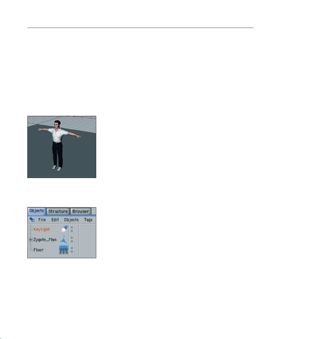
Open a new (empty) scene. Create a oor object (Objects/Scene/Floor). Our Zygote man will
be our lighting victim. You can nd him under (Objects/Object Library/Zygote Man). Adjust his
position so he’s standing on the oor.
Adjust your editor view so the entire gure is visible to you.
A 3-point lighting arrangement begins with setting a key light. As the name suggests, this light
emits the main lighting for the scene and will cast the main shadows. Create a light object
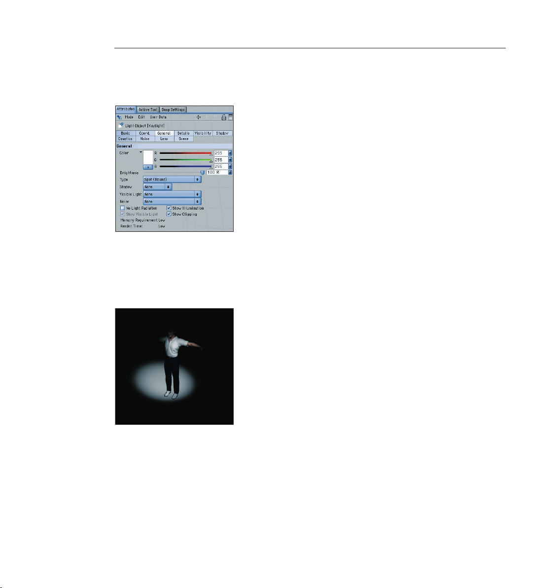
(Objects/Scene/Light). Name it “Main_Light“ in the Object Manager.
CINEMA 4D has several different types of light sources. The key light will always be created by
default. A point light emits from its center in all directions. For our key light we will need a spot
light which we can aim directly onto the object.
Page 46
38 CINEMA 4D R9 Quickstart – Lighting
39CINEMA 4D R9 Quickstart – Lighting
To make the key light a spot simply go to the Attributes Manager and switch the light from
“Point“ to “Spot (round)“.
Now our light source has been transformed to a spot. A spot acts like a ashlight. CINEMA 4D
offers spots with square and round cones of light. This cone is visible in the editor and can be
manipulated. Now we will aim the spot at our gure.
Position the light at the following coordinates in the Attributes Manager: X=300, Y=580,
Z=-300 at an angle of H=45, P=-45 degrees. Render the scene.
The light is now falling at an angle onto our object. Of course the exact position of the light is
strongly dependent upon the camera’s angle. Unfortunately the light is not casting a shadow,
letting the gure look like it’s oating. CINEMA 4D’s lights have an advantage over real light
in that you can choose which kind of shadow, if any, they should cast - a plus for any studio
photographer.
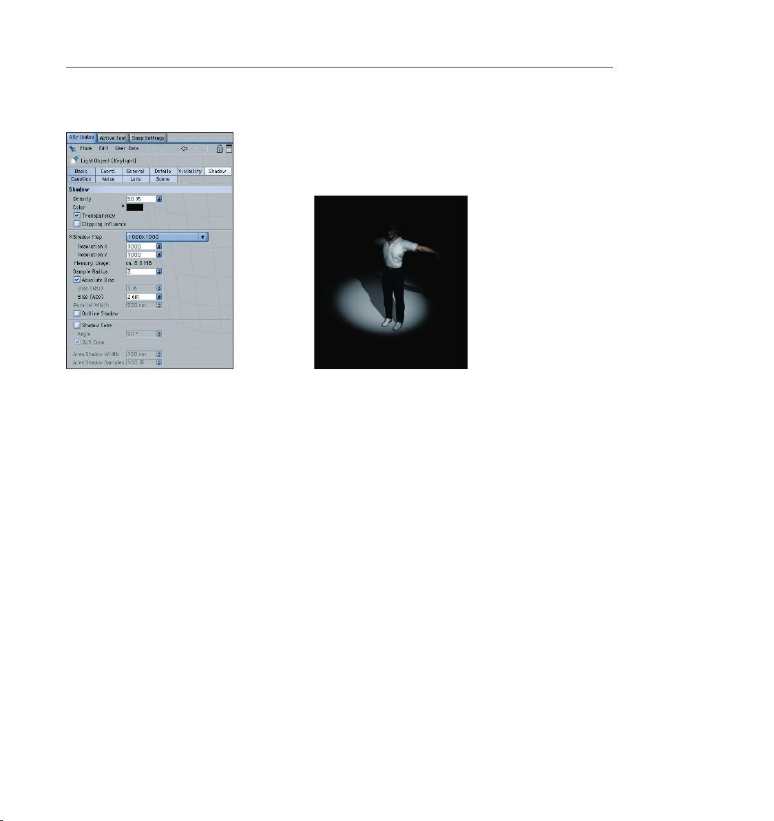
In the “General“ menu of the Attributes Manager, set the light’s shadow to “Soft“. We don’t
want the shadow to be completely black so we’ll make it a little transparent.
Page 47
39CINEMA 4D R9 Quickstart – Lighting
In the “Shadow“ menu, set the shadow density to 50%. Select “1000 x 1000“ as the shadow
map. Render the scene.
CINEMA 4D offers three types of shadows: “Hard“ – a shadow with sharp edges, “Soft“ – a
shadow with soft edges and “Area“ – a shadow that becomes softer the further it’s away from
the object, resulting in the most realistic shadow effect. Try the other two shadow types. Careful,
though, the area shadow can take a long time to render! The larger shadow map allows the
shadow to be rendered more accurately.
Surely you’ve noticed that the light’s cone has not enclosed the entire object. The right arm in
particular is still in the dark.
Switch to the details menu in the Attributes Manager and set the “Inner Angle“ to 30 degrees
and the “Outer Angle“ to 100 degrees.
Page 48

40 CINEMA 4D R9 Quickstart – Lighting 41CINEMA 4D R9 Quickstart – Animation
You will see the result in the editor right away. You can also edit the light’s cone by dragging the
orange handles.
Now we’re happy with our key light. Next we will create a more even lighting by brightening our
gure a little from the other side.
Create another light source in the scene and name it “Brightener“. Place it at the following
coordinates: X=0, Y=225, Z=-150 and at an angle of H=-20, P=-10 degrees. Select “Area“ as
the type of light.
Since the brightness of the lights in the scene is additive, we must “dim“ the brightener a little.
Reduce the “Brightness“ in the “General“ menu to 30%.
This area light illuminates the gure from a different angle and softens the contrast somewhat. It
won’t cast a shadow since this would cause “crossing“ of the shadows and make the object look
bad.
Page 49
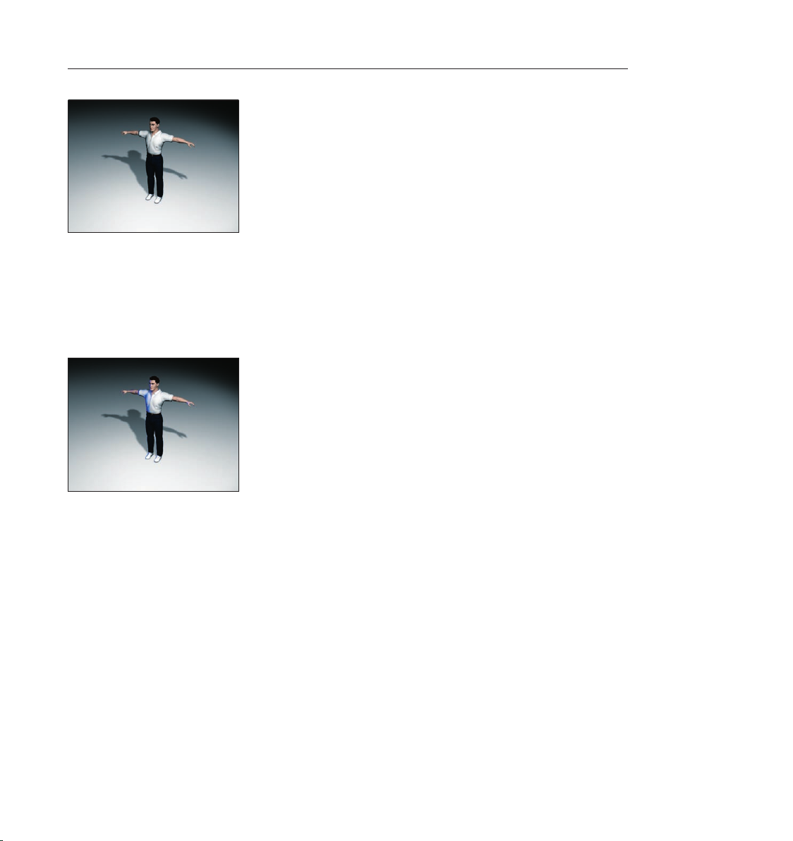
The scene is now pretty evenly lit, but we want to give it a little more pep. Create another light
source, name it “Color“ and, in the Attributes Manager, set its type to “Distant“. Set its color to
royal blue and set its H angle to –90.
The position of a distance light is irrelevant since it always lights your scene in the direction of the
Z axis. This is why we will leave it at the point at which it was created. It gives our Zygote man an
interesting color edge and sets him off of the background a little.
That completes our classic 3-point lighting arrangement. Now the real work starts. If the scene
has a background, which is often the case, it will have to be lit as well. With the proper use of
point lights details in the scene can be “brought to light“ very nicely. But don’t overdo it. With
good lighting, less is often more. Only add lights when necessary and if the scene can actually
benet from them. One more tip before we end: If you have several lights in a scene and are not
sure which light is lighting what, simply make all other lights invisible in the Object Manager. The
light which remains will be the only one visible in the editor.
8. Quick Tutorial – Animation
With but a few exceptions CINEMA 4D lets you animate every attribute of an object. This means
you can alter any attribute in the Attributes Manager over time, whether it’s an object’s Ycoordinates, the color of a light or the strength of an explosion object. By animating different
attributes you can easily add complex animation effects and visually attractive scenes.
Page 50

42 CINEMA 4D R9 Quickstart – Animation
43CINEMA 4D R9 Quickstart – Animation
Just to demonstrate the basic principles of animation, let’s look at a “quick & easy“ example.
Begin by opening a new (empty) scene. Create a cube (Objects/Primitive/Cube).
You will see a blue slider at the bottom of the editor window on which the frame (time) is shown.
This is known as the time slider. By moving this slider you can jump to a different point (time) in
the animation, similar to fast-forwarding or rewinding a lm. You can also use the green arrows
to the right of the slider to play the lm at a predetermined speed.
Further to the right you will see the “record“ button (the red button furthest to the left). You
can use this button to record certain object attributes. Use the buttons to the right of the record
button to set these attributes. With these buttons you can “key“ (record) the position, size,
rotation, attribute and/or point-level-animation of an object at any given time in the
animation.
Make sure the time slider is to the left on 0. Deactivate all symbols to the right of the red
buttons, except the rst (position), and click on the record button.
We have now told the cube that it should stay at its position of 0/0/0 starting at time/frame 0.
In other words, we have generated a key that contains the information on the position of the
cube at time/frame 0. We will tell you later what exactly a keyframe is. Where can you nd this
ominous key? It’s located in CINEMA 4D’s “timeline“. The timeline is where you can change the
position of the keys on the timeline, change the values they contain, delete them, set new keys
and much more.
Switch to CINEMA 4D’s animation layout (Window/Layout/Animation).
Take a look at the timeline at the bottom of your screen. You will see the cube along with a
“track“ for its position. This track contains three “sequences“ (one for every recorded coordinate)
with a gray box at time/frame 0 – a key.
Slide the time slider to frame 90. Move the cube along its blue Z-axis (back) a little. Click on the
record button. Three more keys will appear on the timeline, this time at frame/time 90.
When you move the time slider you can see the cube move between the two recorded points.
Congratulations, you’ve animated the cube! Using the red button to record an object’s changing
Page 51

43CINEMA 4D R9 Quickstart – Animation
attributes is the quickest and easiest way to generate keys. There is a disadvantage, though.
Often, altered attributes will be recorded even if they had not been altered at all. In the case of
the cube it was the X and Y positions. There are other ways in which animation keys can be set.
We will now look at how you can select and animate specic attributes.
Open a new (empty) scene. Create a oor object (objects/scene/oor) and a cone (objects/
primitives/cone). Move the cone up a little along its green Y-axis so that it’s standing on the oor.
The cone has a lot of attributes that we can change using the Attributes Manager. We will now
animate two of these attributes - the upper radius and the number of segments of the cone.
Make sure that your scene is set to frame 0. Hold down the Ctrl key and click on the small gray
circle in front of “Top Radius“. It will turn red.
We just told CINEMA 4D that the “Top Radius“ attribute of the cone at point 0 of the animation
should have a value of 0. Of course we haven’t created an animation yet, only a starting point
for the animation. The lled red circle in front of the attribute name tells us that a key has been
set at this point in time in the animation. This is an easy way to see if an attribute has been
animated. A further ctrl-click on this circle would delete the key.
Go to frame 50.
The lled red circle is now empty. This means that the attribute has been animated at some point
in the timeline but no key exists at this particular point.
Page 52

44 CINEMA 4D R9 Quickstart – Animation
45CINEMA 4D R9 Quickstart – Animation
Change the “Top Radius“ value to 200 and set a second key using the method described above.
Play the scene in the editor and watch how the cone and the value in the Attributes Manager
change.
The cone now knows that at frame/time 50 the top radius has to have a value of 200. All changes
to this attribute between frames 0 and 50 will be ““interpolated”. Interpolated means that
CINEMA 4D automatically calculates the necessary values in between. This means the value at
frame/time 25 of the animation will be exactly 100 since half the time equals half the altered
value of the attribute. The attribute’s value changes over time – it has been animated.
Go back to frame 0. Set a key for the “Bottom Radius“ attribute. Go to frame/time 90. Reduce the
number of segments to 3 and set another key. Play the animation.
Now two of the cone’s attributes have been animated. One changes between frames 0 and 50
and the other between frames 0 and 90. For an overview of the keys that have been set we us the
timeline.
If the timeline is not yet visible, simply open it (window/timeline) or switch to the
predened animation layout (window/layout/animation). In the timeline you can see the cone, its
animated attributes and the keys that were set.
Page 53

At the end of the animation the cone looks completely different. A nice animation such as ours
deserves dramatic lighting so let’s not dwell on the cone anymore and move on to other objects.
Make sure you’re at frame/time zero. Create a light source (objects/scene/light) and position it at
X=200, Y=250. Set the color to a light yellow in the “General“ menu of the Attributes Manager.
Set a key for the color value by ctrl-clicking on the gray circle in front of “Color“.
Go to frame/time 50 and set the color to pink and set a key.
45CINEMA 4D R9 Quickstart – Animation
Now go to frame/time 90, set the color to a friendly blue and set a third key. Play the animation.
Page 54

46 CINEMA 4D R9 Quickstart – Animation
47CINEMA 4D R9 Quickstart – Animation
The cone metamorphosis now takes place in animated light. The color sliders change as the
animation plays and CINEMA 4D interpolates the colors between the keys that were set. Our
animation is becoming more and more interesting. That’s why we don’t want to see it from only
one perspective, but we want to let a camera y around it.
Create a target camera (objects/scene/target camera). Rename the camera in the Object Manager
to “Animated Camera“.
A target camera differs from a normal camera in that it focuses on a specic object. This has the
advantage that the camera can be moved freely within a scene, without “losing sight“ of your
targeted object. When a target camera is created, it places with it into the scene an additional
object, a Null Object named “Camera Target“. This is the object upon which this camera is
targeted by default. In this case we don’t need it because we want to target the camera onto
the cone. Delete the “Camera Target“ in the Object Manager. Click on the cross hairs next to the
camera. Now drag the cone from the Attributes Manager into the “Target Object“ eld in the
“Tag Properties“ below.
Page 55

47CINEMA 4D R9 Quickstart – Animation
In order to view the scene from the new camera’s perspective simply switch to the camera
“Animated Camera“ in the editor menu under “Cameras“. The camera is looking at the scene
from above but is not living up to its name since it’s not animated – yet. We would like to
animate the camera along a circular path around the scene. For this we will need a circle. Create
a circular spline (objects/spline primitive/circle). Set the radius to 1000 and the plane to “XZ“. Set
the spline’s coordinates to Y=20 so the circle is above the oor and angle the spline a little by
setting the P-angle to 30 degrees.
Now we have a circle that encompasses our scene – a track for our camera. We just have to tell
the camera to follow this circle. This is done with a special CINEMA 4D tag.
Using the right mouse button, click on “Animated Camera“ in the Object Manager and select
“CINEMA 4D tag/Align to Spline“ from the menu that appears. A further tag will appear next to
the camera.
This tag has a text eld named “Spline Path“ in the Attributes Manager. Drag the circle from the
Object Manager into this text eld.
Page 56

48 CINEMA 4D R9 Quickstart – Rendering
49CINEMA 4D R9 Quickstart – Rendering
Now the camera is positioned on the circular path. If we play the animation, though, we will be
disappointed because the camera doesn’t move even one millimeter. That’s because we haven’t
yet told it to move along the circular path.
Make sure you set the animation back to 0 and the circle is the active object. In the Attributes
Manager under “Align to Spline“ you will see an attribute called “Position“ which is set to 0% by
default. Set a key for this attribute. Go to frame 90 and set this attribute’s value to 100%. Set
another key and play the animation.
The attribute “Position“ determines how much of the path, in %, will be completed within a
given amount of time (frames). This means that the camera followed 0% of the path at frame
0 and 100% of the path at frame 90. It followed the entire length of the path once.
Make sure you set the animation back to 0. In the “Coordinates“ menu of the Attributes
Manager, set a key for the Y position.
Go to frame 90. In the editor, move the circular path up along its green Y-axis until the camera
has a bird’s eye view of the cone. Key the new Y position.
Now the circular path and the camera move together on the Y-axis in the course of the
animation. With just a few animated attributes we have managed to create a complex animation.
9. Quick Tutorial – Rendering
You’ve been a busy bee. You have created a scene, set up the lighting, animated objects and
assigned materials to them. Now we want to see the result of all this work. What you have to do
is to transform this 3-dimensional scene into a 2-dimensional image (in the case of an animation
it would be an entire series of images. We will “render“ the images. CINEMA 4D offers a wide
variety of options for rendering your 3D scene. We will use a scene from the animation chapter as
our source and we will add a transparent sphere and a bright background to the scene.
Page 57
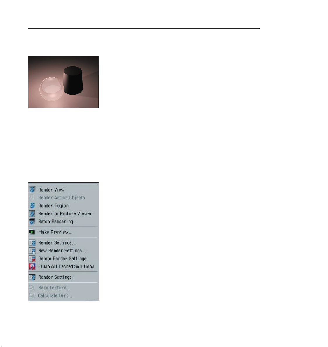
Open the scene “rendering.c4d“ (le/open). Slide the time slider to frame 20 and click on
“Render/Render View“.
We will render frame 20 using CINEMA 4D’s standard settings to give you a quick impression of
how our nal scene will look. This method of rendering is probably the most widely used since it
can be used to make sure the scene “is on the right path“.
Slide the time slider to frame 0 and press “Ctrl+R“ on your keyboard.
The view has been rendered again. There are three ways you can render the active view.
1. Using the main menu
2. The keyboard shortcut “Ctrl+R“
3. By clicking on the icon in the editor window
49CINEMA 4D R9 Quickstart – Rendering
Page 58

50 CINEMA 4D R9 Quickstart – Rendering
51CINEMA 4D R9 Quickstart – Rendering
Use the method with which you feel most comfortable.
Often we don’t necessarily want to render the complete editor view but only a small part of it.
This is also no problem. Select “Render/Render Region“. The cursor will be transformed into a
cross. Drag a frame around the region you wish to render.
The second possibility is to render only a single object.
Select the sphere and the cone in the Object Manager. Select the command (Render/Render
Active Objects).
Only the selected objects will be rendered. You can also access both commands by clicking on
their respective icons.
Rendering the editor view gives us a quick overview of the scene but it does not offer the
possibility to process this image further, to save it to the hard drive, for example. What good is
Page 59

the best rendering if you can’t save the images it generates? Of course there is a command with
which you can do this.
Select “Render/Render to Picture Viewer“ or press “Shift+R“. The picture viewer will open in a
separate window in which the scene will be rendered. When the image has been rendered select
“File/Save Picture As“. A further window will open. Conrm the location with “OK“. (If you are
using CINEMA 4D’s demo version this function will not be available to you).
51CINEMA 4D R9 Quickstart – Rendering
Now you can save any image to your hard drive so you can edit them in an image editing
program or just send them to your grandma via email if you want. Rendering to the Picture
Viewer has the additional advantage that you can continue working on your scene if the image
should take a while to render. You have probably noticed that the image which is rendered to the
picture viewer is very small. 320 x 240 pixels to be exact. Why this size? And what should you do
if you need a larger format? The time has come to make use of the render settings.
Close the picture viewer and open the render settings (Render/Render Settings).
Page 60
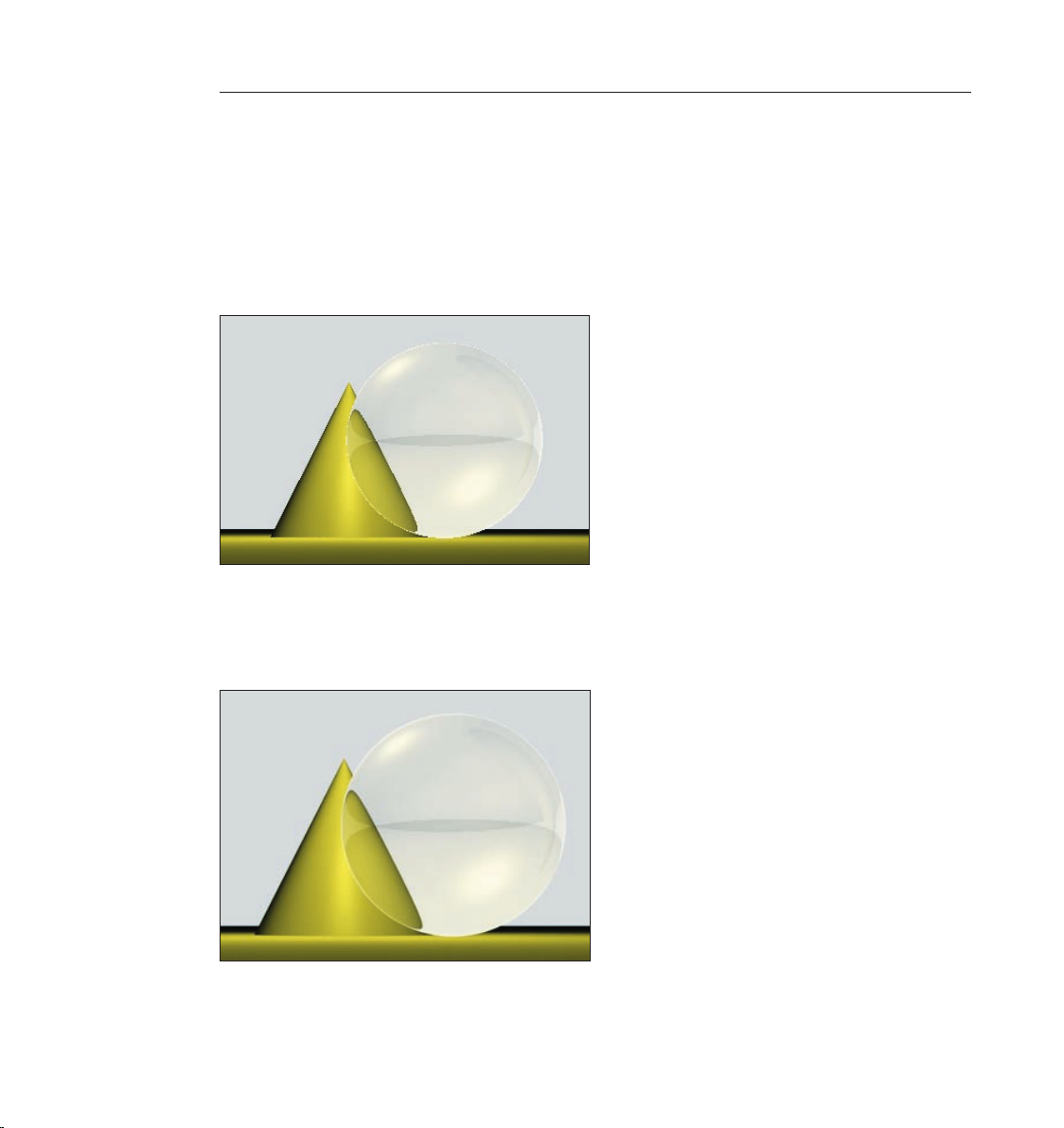
52 CINEMA 4D R9 Quickstart – Rendering
53CINEMA 4D R9 Quickstart – Rendering
You use the render settings to determine what our nal image will look like. Everything from size,
quality, single image or animation can be set here.
In the rst menu, “General“ we can already make settings that will inuence the quality of our
rendering. Take a closer look at the editor rendering of the scene. You can see the cone’s edge
behind the sphere. It looks a little pixelated. You can see a similar effect along the edge of
the sphere. This is called “anti-aliasing“. This term refers to how smoothly an edge has been
rendered.
Set Anti-aliasing to “None“ in the “Render Settings“.
The effect is much worse without anti-aliasing. You can plainly see pixelation along the left edge
of the cone now as well.
Set anti-aliasing to “Best“ and render the scene again. All edges have been rendered sharp as a
knife.
Page 61
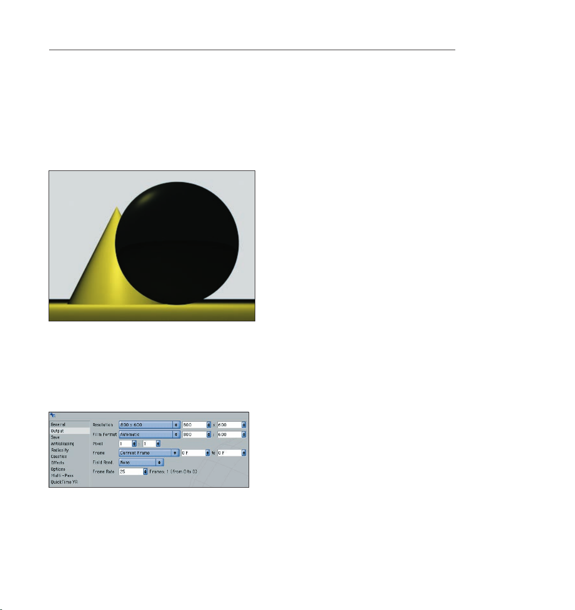
To quickly check the scene you can leave the anti-aliasing set to “None“ or “Geometry“. “None“
renders the edges without anti-aliasing and very quickly. “Geometry“ renders the image with
sufcient smoothing and offers a good compromise between quality and speed. You can select
the best quality when you render the nal image. You can select additional types of anti-aliasing
in the “Filter“ menu. More ne-tuning is possible in the render settings menu.
The render settings “Transparency“, “Reection“ and “Shadow“ can be set depending on how
they are needed. Switch the transparency to “None“ and render the scene. You will see that the
sphere is no longer transparent.
53CINEMA 4D R9 Quickstart – Rendering
Select “Render/Delete Render Settings“. The render settings will be set back to the default
settings. Switch to “Output“ in the render settings.
This is where we will nd out why the image in the picture viewer is being rendered so small.
“Resolution“ lets you choose from a wide variety of image resolutions. You can also simply enter
the desired image size. Slide the time slider back and forth until you nd a frame you would like
to render. Set the size to “800 x 600“ and render the image in the picture viewer.
Now you can see a lot more of the scene. We’ve done enough with single images and want to
move on to an animated scene. We want to set everything in motion. Set the render size back to
“320 x 240“ and “Frame“ to “All Frames“.
Page 62

54 CINEMA 4D R9 Quickstart – Rendering 55CINEMA 4D R9 Quickstart – Multipass-Rendering
CINEMA 4D will now render all of the scene’s pictures. The scene’s length is determined in
the preferences (Edit/Preferences) menu. Our scene runs from frames 0 to 90. We just have to
determine which le format our images will have and where they will be saved.
Switch to “Save“ in the render settings, click on “Path“ and choose a name and a place to save
your lm. Now choose a format – you can use “Quicktime“ or “AVI“.
You can also choose single image formats such as TIFF, for example. CINEMA 4D will then save
90 images for this particular animation. You can then create a lm from these single images
using editing software. Some formats even allow you to save an alpha channel with the image.
Alpha channels help you to cut out objects in the image in an image editing program, letting you
change the background, for instance.
Select “Render/Render in Picture Viewer“ and watch CINEMA 4D work.
In the “Options“ menu of the render settings you will nd further settings that inuence your
rendering. Here you can turn textures off, generate a protocol as a text le and regulate the level
of detail.
Page 63

If all you need is a quick preview of your animation you can save yourself the trouble of always
opening and changing the render settings by selecting the preview function (Render/Make a
Preview). The settings used here are kept to a minimum.
Of course the “Output“ and “Save“ settings depend on the requirements of your scene.
If you render a single image that will be printed with a resolution of 300dpi on a 8.5x11 size
page you should render the image with a resolution of at least 2550 x 3300. If you want to print
the image in a picture size of 3x5, a render resolution of 1000 x 1500 will be more than enough.
By the way, there are many services that will print your digital images. Maybe you can send us
your rst CINEMA 4D work of art as a Holiday card!
Animation is a different story. The frame rate, which is also editable in the “Output“ menu of
the render settings, plays an important role in animation. The frame rate is the speed at which
the animation plays. A frame rate of 25 means that 25 images per second will be played. If you
produce an animation for the European market you will have to adhere to the PAL standard
which uses an output size of 768 x 576 pixels and a frame rate of 25. If you produce a lm the
frame rate must be set to 24 and a much higher resolution that for television.
10. Quick Tutorial – Multi-Pass Rendering
As you have read in the previous chapter rendering can take up a lot of time. The last thing you
want to have to do is render a long animation a second time because you accidentally set a
wrong property. Let’s say you look at your lm again the next day and realize the specular light
on the sphere was set much too bright. Or worse, you’re a 3D professional and a client is looking
over your shoulder telling you he would rather have the pink panther dove blue! Now you have
to create a new texture for the character and render the entire animation again – unless you
had secretly activated multipass rendering. With the help of multipass rendering you can place
3D objects in front of a real background (keyword: compositing) or you can use lters in postproduction to make the images more attractive. In this chapter we will show you how to use
Page 64

56 CINEMA 4D R9 Quickstart – Multipass-Rendering
57CINEMA 4D R9 Quickstart – Multipass-Rendering
multipass rendering so we can take away the hassle of clients who want you to make unexpected
changes to a project ASAP.
Open the le “multipass_e.c4d“. The time slider is set to frame 15. We want to render this frame
and subsequently make changes to it using an image editing software. Open the render settings
(Render/Render Settings) and select multipass.
Multipass rendering means that not only the actual image will be saved but also the individual
channels (passes) which comprise such an image. A channel can, for example, contain an
image’s environment light, specular light, transparency or even single objects. This information
is output as a separate image. These images can be edited individually using an image editing
software and brought together to a single image after editing. In the top right corner of the
multipass settings there is a menu which you can call up by clicking on the arrow which shows all
renderable channels.
Page 65
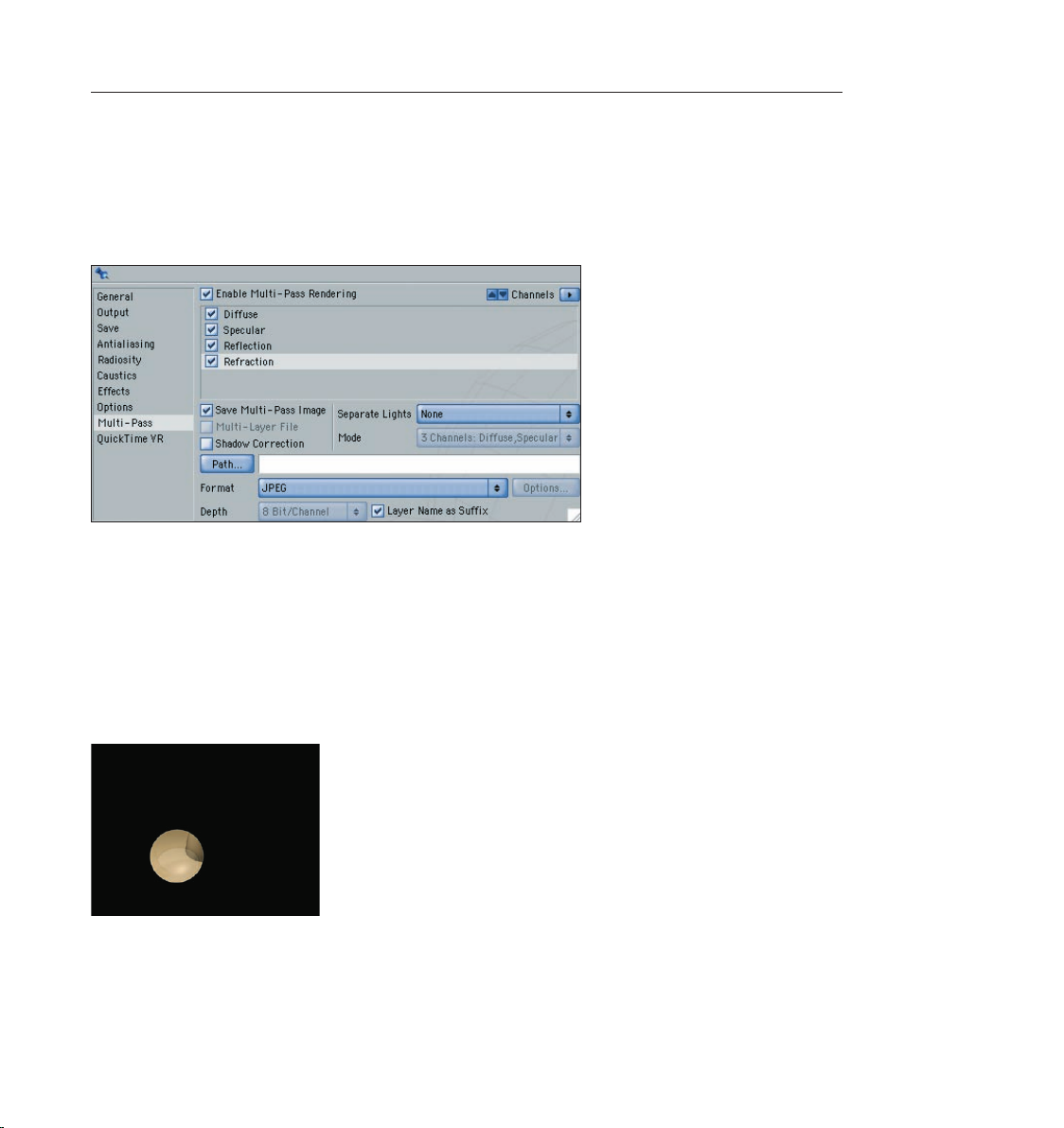
57CINEMA 4D R9 Quickstart – Multipass-Rendering
Set the format to “JPG“ and click on the “Path“ button. Find a place to save the image on your
hard drive and name the image “Multipass_Scene“. (In case you are working with a demo version
you will nd the result of this function in the following les: “scene_diffuse0015.jpg“, “scene_
specular0015.jpg“, “scene_trans0015.jpg“ and “scene_re0015.jpg“. Add the channels “Diffuse“,
“Reection“, “Specular“ and “Refraction“ and render the scene using the command “Render/
Render To Picture Viewer“.
You will not notice anything special when the image is rendered. When you look into the
“channel“ menu of the image viewer you will see that you can call up each of the channels you
just rendered individually. If you now look on your hard drive where you saved the image you
will see four les. Since “Layer Name as Sufx“ was activated in the multipass window each
image was given a name according to its channel: “Diffuse” for the diffuse lighting, “re“ for the
reection, “specular“ for the specular light and “trans“ for the transparency/refraction, each with
the frame number. If you take a look at each image you will see that only the information from
the individual channel is contained in the respective image. In the “trans“ image only the sphere
can be seen since it is the only transparent object in the scene.
But how can we use these images to manipulate our scene after it’s been rendered? By using
an image editing software such as Photoshop. Photoshop is a very popular program which
has established itself as the standard image editing software. If you don’t own a version of
Page 66

58 CINEMA 4D R9 Quickstart – Multipass-Rendering
59CINEMA 4D R9 Quickstart – Multipass-Rendering
Photoshop you can download a demo version from their web site at www.adobe.com. Photoshop
can split an image into several layers. These layers can be mixed in various ways but it would be a
lot of work if we had to open each of our images in Photoshop and mix them manually.
CINEMA 4D makes it possible for you to integrate all layers into one le. This function does not
work for every le format, such as JPEG for example. Since we want to work with Photoshop it
makes sense that we use Photoshop’s own format “PSD“ (Photoshop Document).
Set the format to “Photoshop (PSD)“ in the multipass window. If you have Photoshop 7.0 or
newer, activate the checkbox under “Options“ at the bottom right of the window. Render the
image.
“Multi Layer File“ is automatically activated in the multipass window as soon as we select PSD
as our format. This simply means that all four images will be contained in one image le as
separate layers. Convince yourself: On your hard drive you will see a le named “Multipass_
scene0015.psd“. Users of the demo version will nd this le alongside with the Quickstart PDFdocument. Open the le in Photoshop. The image you just opened looks like the rendered image
in CINEMA 4D. Take a look at Photoshop’s layer palette and you will see our channels, properly
named and linked with each other.
The great thing is that we can change the layers in Photoshop and at the same time the channels
of our rendering. Remember the specular light we mentioned at the beginning of the chapter?
We think it can be a little brighter.
Select the “Specular“ layer in Photoshop and call up the “Levels“ function (Image/Adjustments/
Levels).
Now you’ve already made the specular light brighter without having to render the image again.
Page 67

59CINEMA 4D R9 Quickstart – Multipass-Rendering
You may have noticed that there was a shadow in the original scene that is not visible in the
Photoshop le. This is because the shadow has its own channel and we simply did not activate it
in the multipass rendering menu.
Add this channel in CINEMA 4D, render the image and open it in Photoshop. (For the users of our
demo version: The result reects what you see in “MultipassShadow_Scene0015.psd“). Now the
shadow has its own Photoshop layer. The shadow is very dark and the right edge of the cone can
barely be seen. We want to change that now. Select the shadow layer in Photoshop and set its
“Opacity“ to 50%.
Page 68

60 CINEMA 4D R9 Quickstart – Multipass-Rendering
61CINEMA 4D R9 Quickstart – Multipass-Rendering
The image already looks brighter. And what should we do with the client who wants his pink
panther dove blue? Aside from the fact that our scene contains neither the color pink nor a
panther, what should we do when we want to change the color of the cone only? How do we
change the color of a single object in the scene? For this we have to prepare a little in CINEMA 4D
rst.
Assign a compositing tag to the sphere in CINEMA 4D’s Object Manager under “CINEMA 4D tags/
compositing”. Switch to the “Object Buffer“ menu of the Attribute Manager and activate “Buffer
1“.
The compositing tag makes it possible to assign an image buffer to one or more objects in the
scene. Assign a compositing tag to the cone as well. Activate the second buffer.
Page 69
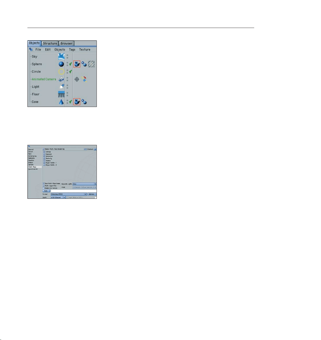
61CINEMA 4D R9 Quickstart – Multipass-Rendering
The sphere and cone are now in two separate image buffers, 1 and 2. Now we have to activate
these buffers in the render settings.
Add 2 “Object Buffers“ in the multipass settings window. For the rst, set the “ID“ to “1“ and for
the second to “2“. Render the scene and open the new le in Photoshop.
At rst glance nothing has changed in the Photoshop le. There are still only ve layers. Where
are the new objects? They can be found in the channel palette. An “Alpha Channel“ was created
for each object. An alpha channel is a gray scale image used to cut out objects in the image.
Page 70

62 CINEMA 4D R9 Quickstart – Multipass-Rendering 63CINEMA 4D R9 Quickstart – XPresso
Select the “Refraction“ layer in Photoshop. Choose select/load selection. Set “Channel“ to “Object
Buffer 1“.
We just loaded the buffer channel as the selection. Various image editing options will now be
limited to the area within this selection – the sphere.
Call up “image/adjustments/hue/saturation. Click on “Colorize“ and set the “Hue“ to 240 and the
saturation to 100.
Page 71

Only the sphere will be colored. Since it consists mainly of refractions, we chose the respective
layer in advance.
Multipass really comes to shine when it’s used with animated scenes. What Photoshop does for
single images, compositing programs do for animations. After Effects and Combustion are two of
these programs. Editing software such as Final Cut lets you edit image layers as well.
CINEMA 4D works with all of these programs, partly over special export plugins which offer an
extensive number of settings. You can change a color in a 15-minute animation in seconds.
11. Quick Tutorial – XPresso
Expressions let you set dependencies for object properties. In other words, you can use rules
to automate a scene: “When object A performs action B object C should perform action D.“
So you don’t have to enter these expressions manually MAXON created XPresso. XPresso is a
graphic interface which puts an end to the cumbersome act of typing code. XPresso lets you
create expressions using drag & drop which is simple (and can even be fun) and offers enough
functionality to be able to solve just about any problem. We will now take a look at what this
problem solving looks like. In this tutorial we will build a kind of telescopic arm.
Open a new scene. Create three cylinders (objects/primitives/cylinder). Rename them into
“cylinder_small”, “cylinder_medium” and “cylinder_big”. In the Attributes Manager set the radius
of “cylinder_medium” to 45, the radius of “cylinder_small” should be 40.
Page 72
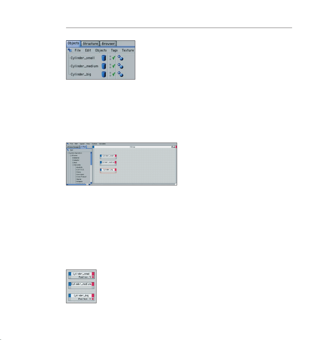
64 CINEMA 4D R9 Quickstart – XPresso
65CINEMA 4D R9 Quickstart – XPresso
We now have three cylinders with different radii in the scene. Our goal will be a telescopic effect
by pulling the smallest cylinder up while keeping the medium cylinder dead center as it moves
with the smallest cylinder. This is a case for XPresso!
Apply a new XPresso tag. The quickest way to do this is to click on one of the cylinders in the
Object Manager with your right mouse button. Select CINEMA 4D Tag/XPresso. By the way, it
doesn’t matter which object you apply the tag to. The XPresso editor will open. Drag all three
cylinders from the Object Manager onto the empty surface of the XPresso editor. The objects will
be transformed into little boxes, so-called “Nodes“.
Nodes are XPresso’s cornerstones. They represent objects or functions. Nodes have an input and
an output which allow them to exchange information with other nodes. You can view a node’s
complete input by clicking on the little blue box in the top left corner of the node. A node’s
output can be viewed by clicking on the red box. Take a look at the exits of the cylinder’s nodes.
Some of them will surely be familiar to you (Attributes Manager).
Think about what it is we want to happen. We want to pull the small cylinder up, ie; change a Yvalue. This movement should in turn inuence the Y-value of the medium cylinder which should
stay exactly in the center of the Y-positions of the big and small cylinders. We can say that we
want to set the medium cylinder to an average value of the other two cylinders.
Click on “Cylinder_big’s“ red corner and select Coordinates/Position/Position Y. Do the same for
“Cylinder_small“.
Page 73
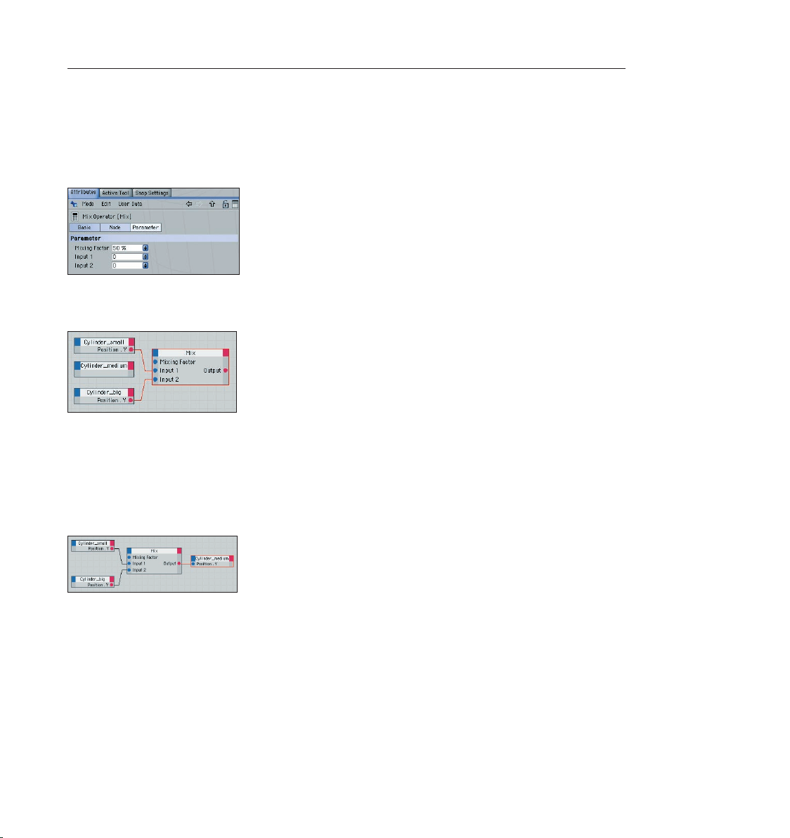
65CINEMA 4D R9 Quickstart – XPresso
Both cylinders can now pass on their respective Y-position. We will use a special node to calculate
the average between these two points.
Switch to the X-Pool tab and drag a “Mix Operator“ node from System Operators/XPresso/
Calculate/Mix onto the surface where the other nodes are. Set the “Mix“ node’s “Mixing Factor”
to 50% in the Attributes Manager.
Connect the “Cylinder_small“ “Position.Y“ output to the “Mix“ node’s input 1 and the “Cylinder_
big“ exit to the “Mix“ node’s input 2.
Both Y-positions will now be transmitted to the “Mix“ node which will now calculate their
average of their respective values. The 50% setting makes sure the values will be mixed evenly.
The result will be the Y-position of the medium cylinder.
Click on the blue corner of the “Cylinder_medium“ node and open an input for the Y-position
(Coordinates/Position/Position.Y). Connect the “Mix“ node’s output with the input of “Cylinder_
medium“ node.
Now gaze in amazement at the result in the editor window. Move the small cylinder along its
green Y-axis. The center cylinder aligns itself automatically.
Page 74

66 CINEMA 4D R9 Quickstart – XPresso 67CINEMA 4D R9 Quickstart – Tips & Tricks
We still have one problem: you can still drag the cylinder so far that our telescope comes apart.
It would be nice if we could restrict the movement a little. Needless to say XPresso also has a
solution for this!
Go back to X-Pool and drag a “Clamp“ node into the XPresso editor. Set its “Max“ value to 300 in
the Attributes Manager.
The “Clamp“ node restricts various properties that are transferred to its “Value“ input to a range
between 0 and 300. Now we just have to connect the node to the rest of the setup.
Click on the blue corner of the “Cylinder_small“ node and open an output for the
Y-position (Coordinates/Position/Position.Y). Drag “Cylinder_small“ from the Object Manager
into the XPresso editor again and open an output for the Y-position. Connect this output to the
“Value“ input of the “Clamp“ node. Connect the output of the “Clamp“ node to the “Position.Y“
input of the “old“ “Cylinder_small“ node.
Page 75

Now the cylinders can only be moved a limited distance in the Y-direction, just like a real
telescope.
12. Tips & Tricks
CINEMA 4D has been able to build a large community of users around it who are more than
happy to help newcomers in any way possible, be it through the use of home-made tutorials,
directly in one of the many forums or by offering free models, plugins, expressions or textures.
One of the main sources of information, of course, is the MAXON web site www.maxon.net.
Here you will nd news, interesting projects that were done with CINEMA 4D, an extensive
CINEMA 4D link library and even a form for questions for our support department. You can even
get information about third party seminars and training.
The Plugin Cafe is a sister site to the MAXON web site www.plugincafe.com.
If you’ve pushed your skills to the limit or if you are looking for a specic tool you can probably
nd what you need at this site. You will nd an extensive collection of plugins, expressions,
interfaces and BodyPaint brushes, many of them free. There is even access to CINEMA 4D’s
Software Development Kit (SDK) for those who would like to program their own plugins. The SDK
documents how CINEMA 4D works and how you can expand it.
A large selection of books is also available for those who would like to expand their CINEMA 4D
library. There are books from the basics to specialization such as character animation. Just enter
the keyword CINEMA 4D into the search engine of your favorite online book store.
Flipping through books which don’t have anything to do with computer graphics can also be
helpful. 3D is a complex eld in which many of the classic arts and techniques are combined.
Books about photography, lighting, direction, acting, image creation and painting should
be part of every serious 3D artist’s library. In addition, you will nd a wealth of information on all
of these topics online.
Eadweard Muybridge’s photo books are especially good for character animators. Muybridge
was known for his photographic depiction of human and animal motion. You will nd examples
of some of these under http://web.inter.nl.net/users/anima/chronoph/muybridge/index.htm.
Page 76
68 CINEMA 4D R9 Quickstart – Tips & Tricks
69CINEMA 4D R9 Quickstart – Tips & Tricks
These Muybridge photos are a must if you’re studying character animation. An online search for
his name will be worth the effort.
3D models are being offered online in all quality and price classes. Two well-known sources are
“TurboSquid“ and “ModelBank“. Both websites offer access to the CINEMA 4D object database.
You will nd more than just models here - textures, plugins and even motion capture les that
can be imported into CINEMA 4D via the fbx format. Commercial sites also offer a wealth of
content.
If you’re looking for advice and don’t want to test the MAXON support just yet you can nd
help quickly in the CINEMA 4D forums. These are independent discussion forums in which
users can meet to help each other with problems or to “just talk 3D“. Here you won’t have to
wait long for an answer. Since many topics have been discussed here already it’s advisable to
search the archives rst. Chances are you will nd the solution to your problem in the archives.
The C4D forum is a part of the “C4D meet“, a so-called portal site that offers information about
CINEMA 4D around the clock. These portal sites are perfect place to rummage for information.
A couple of large English language portal sites that deal with 3D and CINEMA 4D are CGTalk
(www.cgtalk.com) the PostForum (www.postforum.com) or Renderosity (www.renderosity.com).
Here you can nd out what’s going on in the “3D scene“.
Another English language portal site with extensive information about animation is the
“Animation World Network“ (www.awn.com). Here you will nd anything and everything that
has to do with classic and computer animation.
Since the internet is always changing, doing a search for “CINEMA 4D“ in various search engines
(such as “Google“, www.google.com) would be a good idea.
Page 77

69CINEMA 4D R9 Quickstart – Tips & Tricks
Google is also a good source for nding models. Through its special image search function you
can nd photos or drawings of practically any object. Corbis (www.corbis.com) can also be a
good source of ideas.
Even mail order catalogues can be a great source of information on how an object is supposed
to look. Textures are all over the internet as well. Taking your camera and photographing textures
yourself is even better. Inspiration is everywhere. You can build your own texture archives in no
time.
Try to get away from the technical point of view. Learning a software is only a matter of time. A
good 3D artist has the ability to use software as a tool that helps him realize his ideas. The real
creativity lies with the idea, not the software. So when you create your next scene don’t worry so
much about creating the perfect object. Concentrate rather on how you can make a harmonious
composition with this object with a tting theme and proper lighting. Also, think about the
message you are trying to send to the viewer. The same goes for animators. A technically perfect
animation is a great achievement but it will put your audience to sleep if the concept is bad. It’s
not so bad, on the other hand, if your animation is a little bumpy and imperfect but your story
touches the viewer.
We hope this manual has helped you to master the technical part of 3D graphics. What you do
with what you’ve learned is in your hands.
Page 78

70 CINEMA 4D R9 Quickstart – Advanced Render
71CINEMA 4D R9 Quickstart – Advanced Render
Welcome to Advanced Render
(Optional module)
This is the Quickstart Tutorial for the Advanced Render Module. It will show you many of the
module’s typical applications and covers some theoretical physics behind the effects.
1. Introduction
The Advanced Render Module expands the realm of possibilities of CINEMA 4D’s renderer with
several fascinating functions. Users who want to make photorealistic renderings will nd these
functions especially interesting. The module integrates itself seamlessly into existing rendering
settings which makes learning to use it a simple matter. The module adds the following functions
to the standard renderer: radiosity (a rendering method for especially realistic lighting), caustics
(achieves lighting effects on mirrored and transparent materials), depth of eld, specular lighting,
glows and sub-poly displacement.
2. General Information/Interface
As soon as you have installed Advanced Render you will notice several new options in your render
settings (Render/Render Settings). Under “Radiosity“ you can activate “Radiosity Rendering“. As
soon as you have activated “Radiosity Rendering”, other options will be made active which allow
you to create custom settings for radiosity. A material’s “luminance“ channel is closely associated
with this eld. These settings let you determine if a particular material should be rendered with
radiosity. Further settings can be applied to individual objects using the “compositing tag“.
Caustics acts in a similar fashion. The global settings can be found under “render settings“. Here
you can activate or deactivate surface and volume caustics separately. Options relating to specic
materials can be set in the luminance channel. In addition, caustics also offers a third setting.
You will nd this in the light object. The use of caustics requires at least one light object. Within a
Page 79

71CINEMA 4D R9 Quickstart – Advanced Render
light’s caustics menu it is possible to determine whether the light source should generate surface
or volume caustics.
“Depth of eld“, “highlight“ and “glow“ are so-called post effects. You will nd them in
the render settings under “effects“. Further settings for “depth of eld“ can be made in each
camera’s attribute settings. A post effect will rst be calculated after an image has been
completely rendered. You can imagine it as a layer which is placed on top of the image after it
has been rendered.
The Sub-Polygon Displacement can be activated in a material’s “displacement“ channel.
Page 80
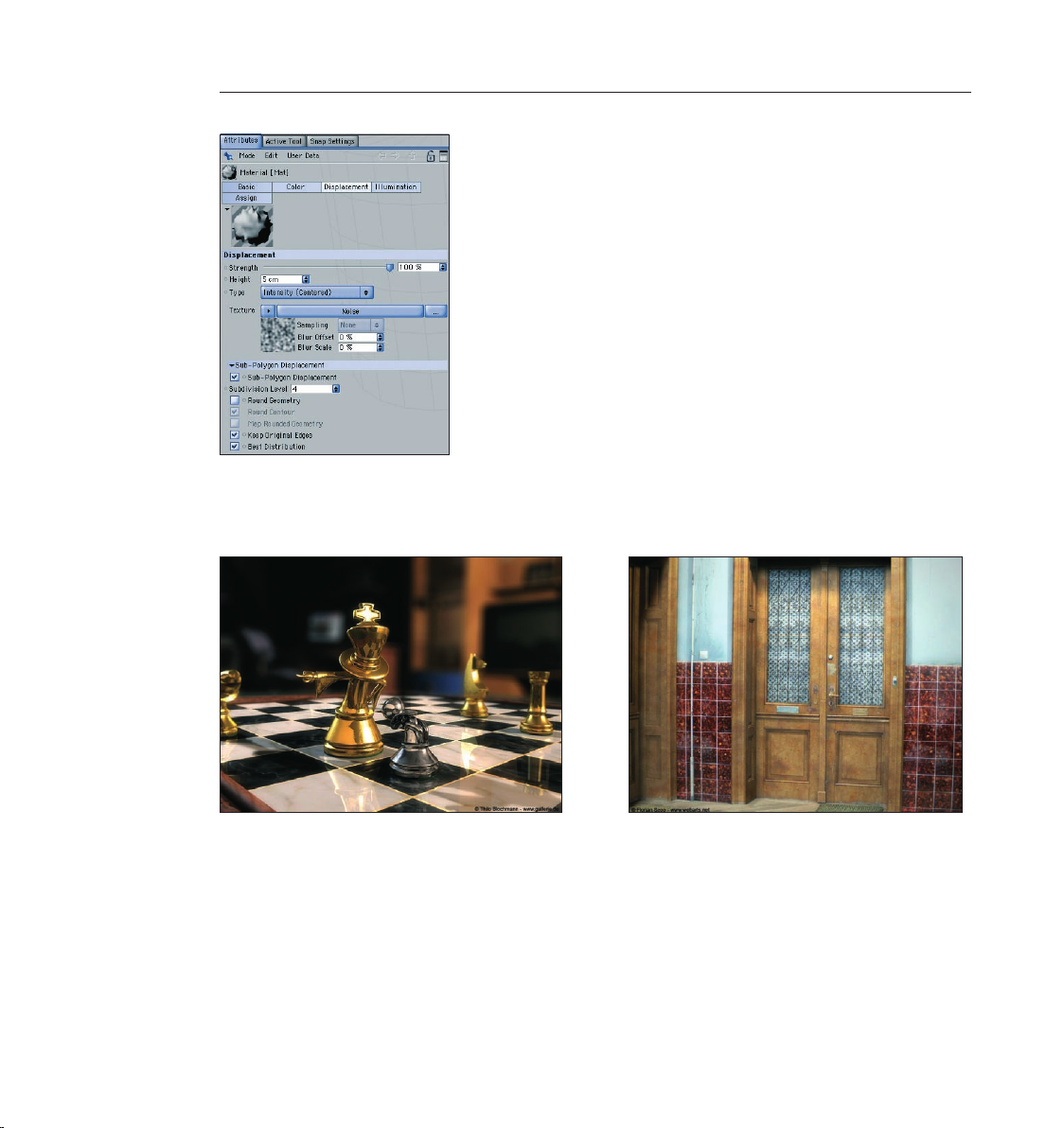
72 CINEMA 4D R9 Quickstart – Advanced Render
73CINEMA 4D R9 Quickstart – Advanced Render
3. Sample Images
Here you can see what’s possible with the Advanced Render functions.
Page 81

73CINEMA 4D R9 Quickstart – Advanced Render
Page 82
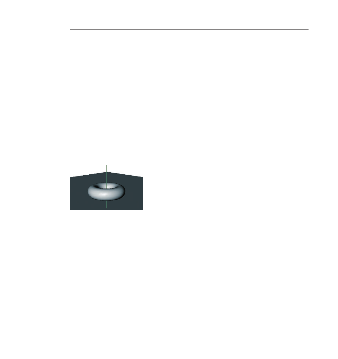
74 CINEMA 4D R9 Quickstart – Advanced Render
75CINEMA 4D R9 Quickstart – Advanced Render
4. Quick Tutorial – Radiosity
Light as we know it in the “real“ world spreads on its own. It is reected by the objects it hits.
This differs depending on an object’s surface characteristics. Imagine a room with a window on
one wall. Light is being cast through the window onto the oor of the room. The light doesn’t
stop there, but is reected from the oor onto other objects which, in turn, reect the light
themselves. The room is lit by “diffused“ (indirect) light.
The raytracing procedure takes into account diffused light. For example, if only one light is used,
everything lying in the shadows will not be visible. Maybe you have already built a virtual room
into which a light source is shining through a hole in the wall. The light in the virtual world hits
an object, lights it – and that’s it. The light spreads no further. Radiosity rendering is different.
Radiosity rendering lets every object within the scene act as a light source. As you will see, you
can actually light a radiosity scene without using a single light!
Open a new (empty) le. Create a sky object (objects/scene/sky) and a oor object
(objects/scene/oor). The sky object encompasses the entire scene like a large sphere. The oor
surface is an innite surface.
Create a torus (objects/primitive/torus) and move it to a y-position of 100, slightly above the oor.
Now we will light the scene with diffused light using radiosity rendering. We will use our sky
object as the light source.
Switch to the Material Manager. Create a new material (le/new material). Switch to “basic“ in
the Attributes Manager. Deactivate “color“ and “specular“ and activate “luminance“. Drag the
material from the Material Manager onto the sky object in the Object Manager.
Page 83
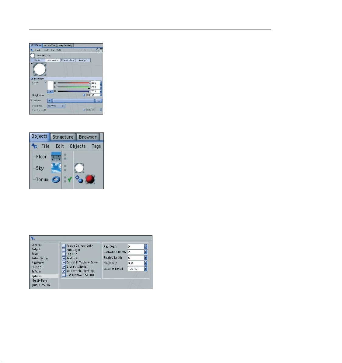
Create another material and give it your favorite color. Drag this color onto the torus.
The luminance channel turns the material into a light source. Since the sky object spherically
encloses the entire scene. It acts as a huge lamp which lights the torus from all sides. This effect
will only be visible when we use radiosity as the render mode.
Open the render settings (render/render settings). Switch to radiosity and activate radiosity.
Switch to the options menu and make sure that “Auto Light“ is deactivated.
75CINEMA 4D R9 Quickstart – Advanced Render
Rotate the scene in the editor viewport so the camera is at such an angle as to show only the
oor in the background. This speeds up rendering since the rendering will only be done to the
“horizon“. Render the scene.
Page 84

76 CINEMA 4D R9 Quickstart – Advanced Render
77CINEMA 4D R9 Quickstart – Advanced Render
CINEMA 4D will automatically turn on Auto Light in a scene if there are no light objects present.
When using radiosity, this automatic function is excluded since it would make the scene much
too bright.
A radiosity scene normally takes much longer to render than a raytracing scene. The scene is
rendered in two passes, thus offering a more realistic result. Notice the soft shadows and the
fact that the red of the torus is somewhat reected onto the oor. In addition, the torus is
lit somewhat by the light reected from the oor below. Of course radiosity lighting can be
combined with “normal“ light sources which may be necessary when darker shadows are needed
Create a sphere (objects/primitive/sphere). Move the sphere along the X-axis a little to the right so
until its next to the ring. Copy the sky material and switch to the luminance channel of the new
material. Use the color sliders to create a bright blue and set the brightness to 100%. Drag the
material onto the sphere.
We now want to use the blue sphere as a light. We don’t want the sphere to be visible, but only
to emit its blue color. You achieve this by using the “compositing tag“.
Apply a compositing tag to the sphere in the Object Manager (File/CINEMA 4D-tags/compositing
tag). Switch to the Attributes Manager and deactivate all options except “Seen by GI“ (GI stands
for Global Illumination). Render the scene.
Page 85
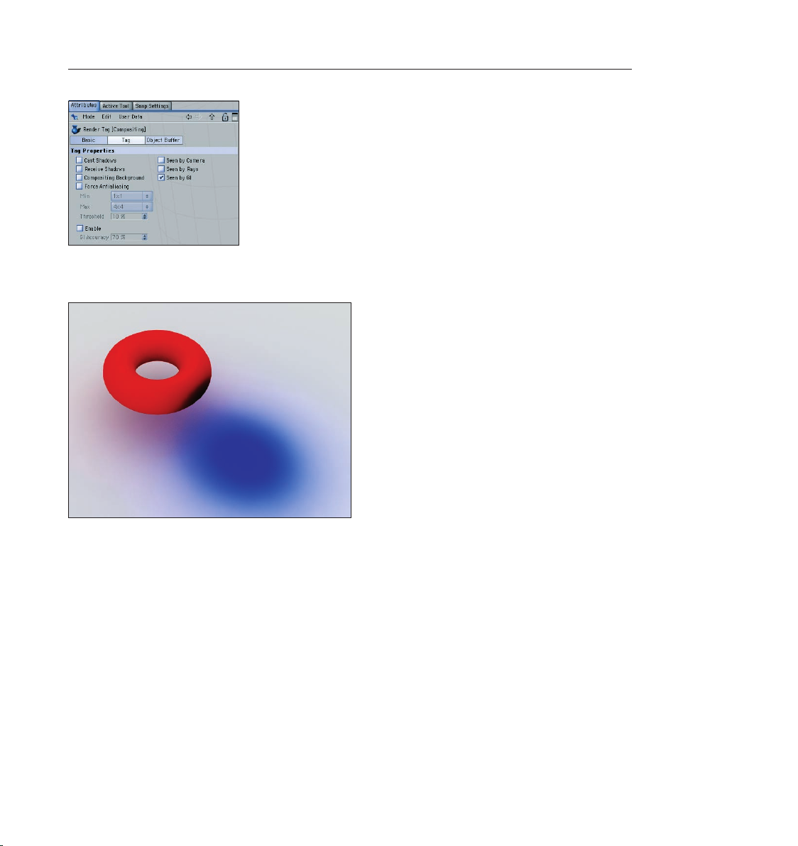
You will see that a blue light is being cast on the torus and the oor. The blue sphere is not
rendered because we have made it invisible using the camera’s compositing tag.
77CINEMA 4D R9 Quickstart – Advanced Render
5. Quick Tutorial – Caustics
Have you ever observed the lighting effects at the bottom of a swimming pool? This phenomena
is known as caustics – light is cast through a transparent material and is broken upon entry and
exit.
Open another new (empty) scene. Create a oor object (objects/scene/oor). Create a platonic
(objects/scene/platonic) and give it a Y-position of 140 using the Attributes Manager.
Page 86

78 CINEMA 4D R9 Quickstart – Advanced Render
79CINEMA 4D R9 Quickstart – Advanced Render
Create a new material in the Material Manager. Activate the transparency channel in the
Attributes Manager and switch to the “Transparency” menu. Set the color to blue. Set refraction
to 1.4 and drag the material from the Material Manager onto the platonic object in the Object
Manager.
If we would have left the setting at 1 the light would have passed through the object unbroken
without a caustics effect. Create a light (objects/scene/light). Place it at the following position:
X=270, Y=300, Z=100 at an angle of H=70 degrees, P=25 degrees using the Attributes
Manager.
The light is now shining through the object onto the oor. Render the scene.
Part of the light is falling on the platonic, part of it is falling on the oor. Still there is no caustic
effect anywhere in sight - the effect must rst be activated. Select the light and switch to the
caustics page of the Attributes Manager. Activate “surface caustics“ for the light.
Page 87
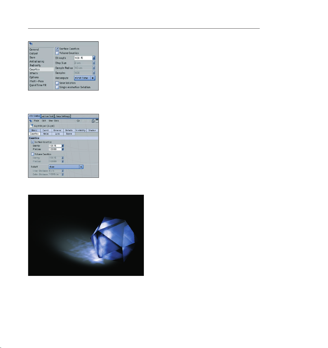
79CINEMA 4D R9 Quickstart – Advanced Render
Open the render settings menu (render/render settings). Activate “surface caustics“ in the caustics
menu here as well.
Render the scene. The caustics effect should now be visible on the oor.
Page 88
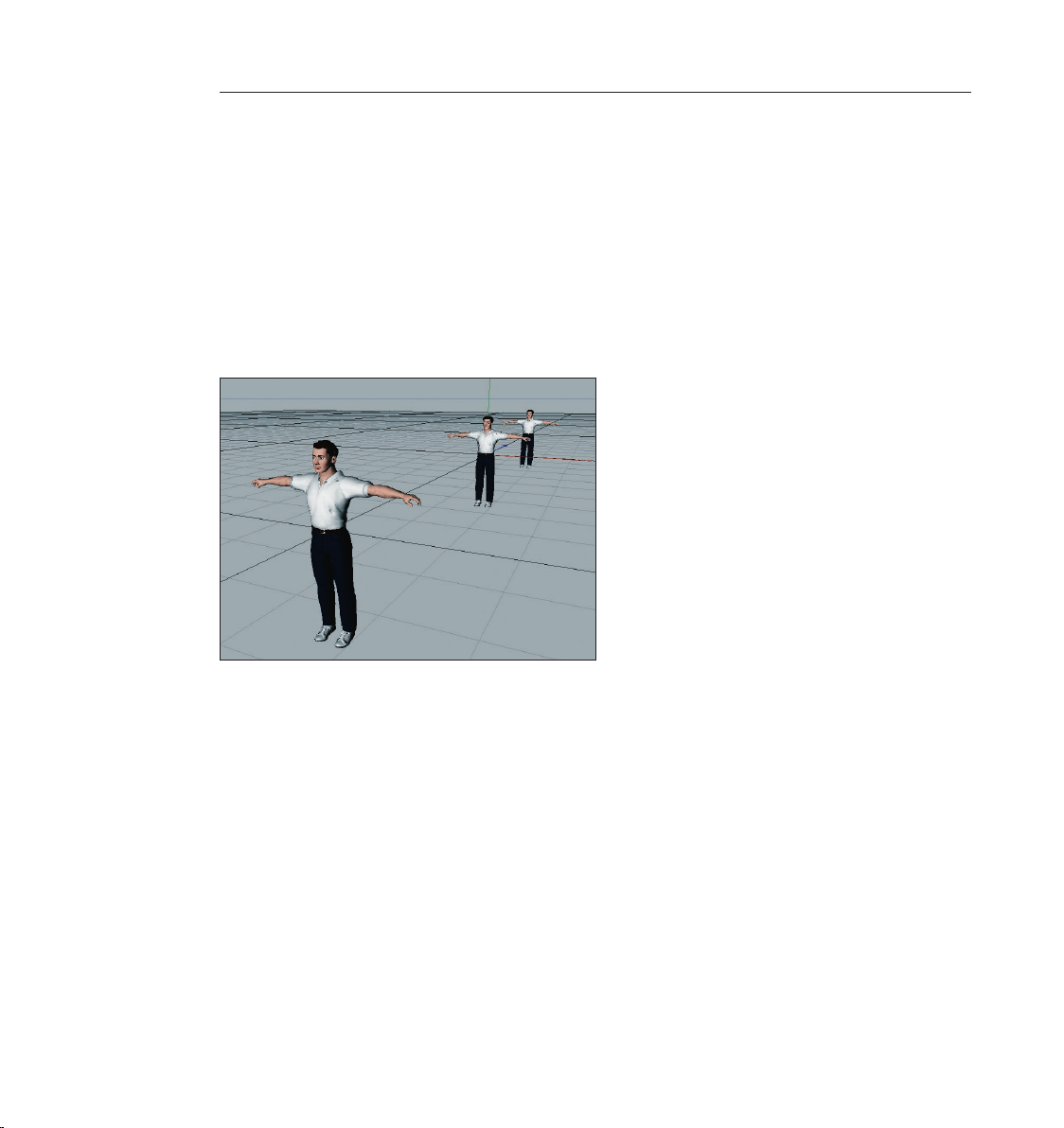
80 CINEMA 4D R9 Quickstart – Advanced Render
81CINEMA 4D R9 Quickstart – Advanced Render
6. Quick Tutorial – Depth of Field
You probably are familiar with the depth-of-eld effect from the eld of photography. Depending
on which lens is used in which combination of camera settings it can only be focused on one
more-or-less small area at once – everything outside this area is out of focus. This effect is often
used as a dramatic element in movies to draw the viewer’s attention to a specic element in the
scene. Of course CINEMA 4D’s Advanced Render Module also offers this technique – as we will
now demonstrate.
Open a new (empty) scene and create three male or female models (objects/object library/zygote
man or zygote woman). Move one of the gures along the Z-Axis to Z=-1000 and the other to
Z=1000.
Create a camera object (objects/scene/camera). Place the camera at the following position:
X=370, Y=200, Z=1500 using the Attributes Manager,. Set the angle at H=25 degrees, P=17
degrees. In the editor window’s menu choose (objects/scene/camera). The editor view will switch
to the camera’s view. All three gures should be visible.
Now we’ll make the settings for the depth of eld. Switch to “depth“ in the camera menu of the
Attributes Manager. Set the target distance to 1500 and set “front blur“ and “rear blur“ to a start
value of 100 and an end value of 1000.
Page 89

81CINEMA 4D R9 Quickstart – Advanced Render
The target distance is the point of focus of the camera. An object located 1500 units from the
camera object – as is the case with our gure located in the center – will appear the clearest.
Objects located in front of or behind this object will be rendered out of focus. Simply activate this
effect in the render settings to make this effect visible.
Open the render settings and switch to “effects“. Select “depth of eld“ in the pull-down menu
at the top right and increase the “blur strength“ to 5%. This makes the effect more obvious.
Render the scene. Only the gure in the center will be in focus. You can customize the strength of
the effect using the parameters in the render settings.
Page 90

82 CINEMA 4D R9 Quickstart – Advanced Render 83CINEMA 4D R9 Quickstart – Sketch and Toon
7. Tips & Tricks
Rendering often requires you to make a choice between speed and quality. Renderings with
radiosity or caustic effects can take especially long to render. This is why we suggest that you
experiment with the settings a little. For example, you can set the radiosity’s “accuracy“ value
very low to start with and try a “quick“ test rendering. If the quality of the rendering still needs to
be improved (if pixels are visible, for example) simply raise this value step-by-step. It’s a good idea
to save these settings together with your scene.
Make generous use of compositing tags. This makes it possible to reduce the exactness of the
rendering, thus reducing rendering times greatly.
As you already know, CINEMA 4D allows you to animate effect parameters so that you can
make changes to them at any time. Imagine caustics that change as you wish or the focusing of a
camera.
Load a bitmap image in place of a color into the luminance channel of a material that you use to
illuminate a radiosity scene. The objects will then be lit with the colors of the image. This looks
especially good if you use so-called HDRIs. HDRI is an image format that contains special image
luminance information and is thus an excellent choice for this effect. You can nd information
about HDRIs at www.debevec.org.
You can pep up your scene even more with the post effects “Specular“ and “Glow“. Using
“Specular“ you can give your material’s highlights any form you wish, like a star, for example.
“Glow“ does just what the name says – it lets a material glow. Try it!
If you wanted to deform an object in the past using a material’s displacement channel, it
was necessary to subdivide the object to such a degree as to allow the gray scale image in the
displacement channel to create the desired effect. This often resulted in a very high polygon
count. “Sub-Polygon Displacement“ puts an end to this problem. The subdivision of an object is
done “dynamically“ during rendering, which leads to spectacular effects!
Page 91

Welcome to Sketch and Toon
(Optional module)
This is CINEMA 4D’s Quickstart Tutorial for its Sketch and Toon module. It will introduce you to
some of this renderer’s fantastic creative possibilities.
1. Introduction
Sketch and Toon belongs to the NPR family. This is an acronym for “Non-Photorealistic Renderer“
and simply means that it’s not the renderer’s intention to generate highly realistic images but to
do exactly the opposite: To generate images that look like they were created using “traditional“
animation techniques. Do you want your scene to look like a technical blueprint or maybe a
pencil sketch? Do you want to give your animated characters that traditional animation look? No
problem for Sketch and Toon!
Sketch and Toon is very easy to operate. For instant results you can fall back on one of the many
presets Sketch and Toon provides. Otherwise you can have a ball with Sketch and Toon’s different
settings. You will quickly realize that Sketch and Toon is a very powerful tool that offers limitless
possibilities. You can take inuence on practically any imaginable parameter. This gives you a
cornucopia of render styles and you will never break the boundaries of Sketch and Toon – we
promise! If you want to get a taste of how you can metamorphose your images just skip ahead
to our gallery.
2. General Information/Interface
Sketch and Toon is a render effect. As you would expect you can nd its settings in the Render
Settings (Render/Render Settings) “Effects“ menu. As soon as you have selected “Sketch and
Toon“ from the “Enable Post Effects“ menu a wide array of settings is put at your disposal. These
parameters let you determine the basic look of your Sketch and Toon renderings.
Page 92
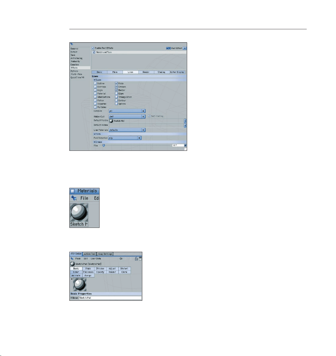
84 CINEMA 4D R9 Quickstart – Sketch and Toon
85CINEMA 4D R9 Quickstart – Sketch and Toon
There’s more. You will also nd Sketch and Toon elsewhere within CINEMA 4D. Take a look at
the Material Manager. A sketch material is created as soon as the Sketch and Toon effect has
been activated. This is a material especially for the depiction of contours in a Sketch and Toon
rendering.
You will also see that there are many more settings in association with this material in the
Material Manager. These settings are global and affect the entire scene.
Keep this general rule in mind: The sketch attributes in the render settings determine WHAT will
be rendered (contours? Hidden lines?), and the material attributes determine HOW something
Page 93

will be rendered (Line width? Line color?). Of course not every object has to be rendered in the
same style. You can create an arbitrary amount of sketch materials and assign them to different
objects. This makes combining a pen drawing with a cartoon object no problem.
After all, Sketch and Toon offers four “Sketch Shaders“. These can be placed into the channel of
a “normal“ material just like any other shader. We suggest you place them into the luminance
channel. These shaders work independently, which means Sketch and Toon does not have to be
active. The shaders are; “Art“ for effects such as oil or acrylic painting, “Cel“ for a cartoon-like
style, “Spots“ for a halftone print effect and “Hatch“ for cross hatching.
85CINEMA 4D R9 Quickstart – Sketch and Toon
Page 94

86 CINEMA 4D R9 Quickstart – Sketch and Toon
87CINEMA 4D R9 Quickstart – Sketch and Toon
3. Sample Images
Here is a sample of the beautiful imagery you can create with Sketch and Toon.
Page 95

4. Quick Tutorial – Outlines
The moment of truth has come. Once you have worked your way through this tutorial you
will have but a rst impression of what you can to with Sketch and Toon. Sketch and Toon is a
module that practically seduces you to experiment with it – give in to its seduction!
Open the le “schraubkopf_e.c4d“. This scene is comprised of a head made up of just a few
primitives.
Let’s have a look at how this all looks once it has been rendered with Sketch and Toon.
Open the render settings (Render/Render Settings). Switch to “Effects“ and select
“Sketch and Toon“ from the “Post Effects“ menu. Render the scene.
87CINEMA 4D R9 Quickstart – Sketch and Toon
The result looks much different from the rst rendering. All objects have a black contour and
the color gradations are somewhat “stepped“. Notice that a new “Sketch Material“ has been
generated in the Material Manager. The look of the contour is dened in this material.
Switch to the “Effects“ menu within the “Render Settings“ menu and click on “Load Style“.
Page 96
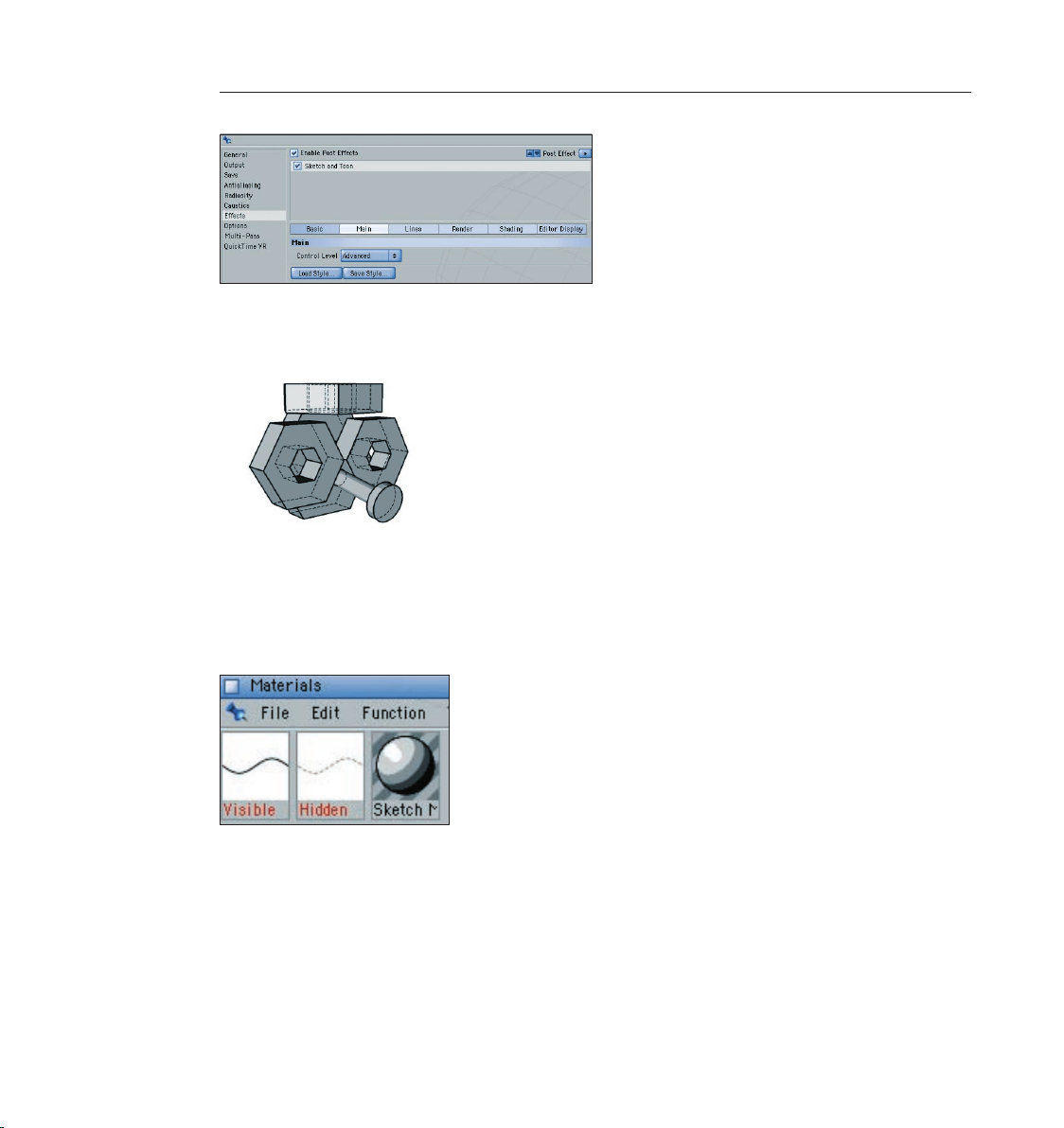
88 CINEMA 4D R9 Quickstart – Sketch and Toon
89CINEMA 4D R9 Quickstart – Sketch and Toon
Navigate to your CINEMA 4D directory. You will nd a number of presets under Library/Sketch/
Styles. Select “technical.c4d“. This style is good for technical illustrations. Render the scene.
Again the rendering looks different. Now the lines which are normally hidden are displayed
as dashed lines. Along with the preset two additional materials were placed into the Material
Manager – “Visible“ and “Hidden“. “Visible“ denes the look of the visible lines and “Hidden“
that of the hidden lines. The “Sketch Material“ is no longer being used.
Let’s bring some color into play. Switch to “Shading“ in the sketch settings. Use the color sliders
to set the “Background“ color to a discreet blue (or your favorite color).
Page 97
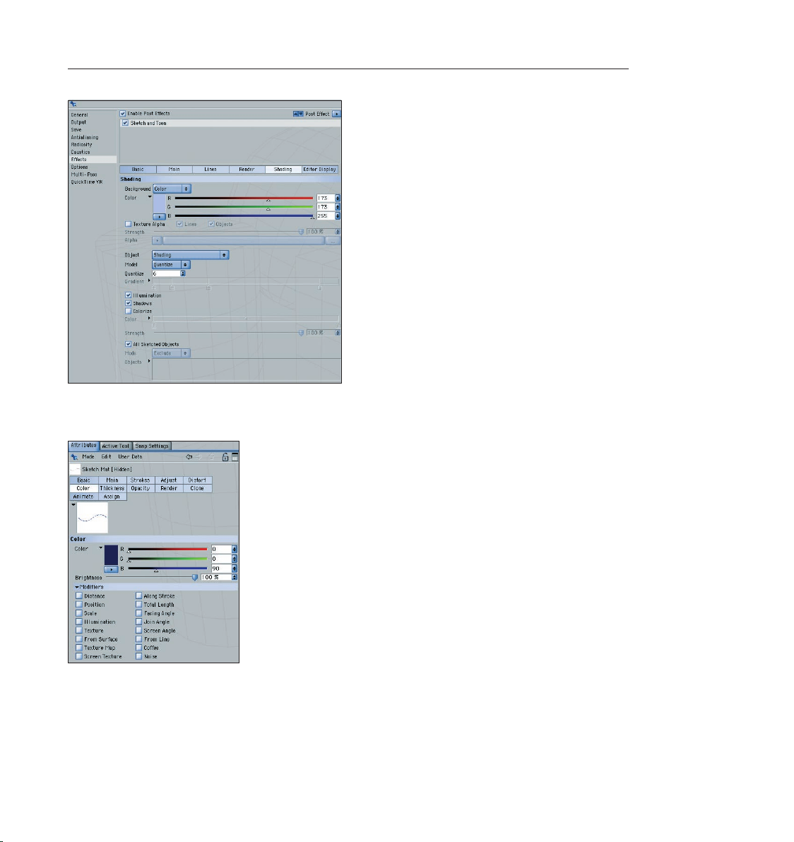
Select the “Hidden“ material in the Material Manager and switch to “Color“ in the Attributes
Manager. Use the color sliders to set the color to a dark blue tone. Render the scene.
89CINEMA 4D R9 Quickstart – Sketch and Toon
We can use the render settings to inuence the entire scene and the material settings to
specically affect the hidden contour. Select the “Visible“ material and switch to “Main“ in the
Attributes Manager. Select the “Pen (Leaky)“ style in the “Presets“ menu. Render the scene.
Page 98
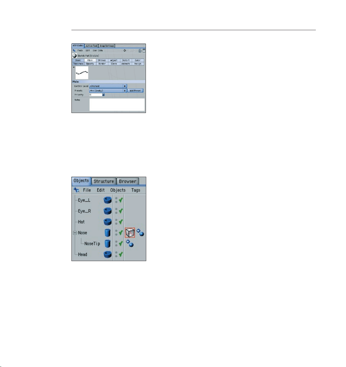
90 CINEMA 4D R9 Quickstart – Sketch and Toon
91CINEMA 4D R9 Quickstart – Sketch and Toon
The visible lines already look like they were drawn with a leaking fountain pen and the hidden
lines are still dashed. Go ahead and try out more of the presets!
Until now changes to the sketch settings have had an effect on all objects in the scene. We can
also choose to change the look of only one specic object.
Select File/New Material/Sketch Material in the Material Manager. Drag the material from the
Object Manager onto the “Nose“ object. A “Sketch Style Tag“ will appear next to the object.
Select this tag.
You will see several settings in the Attributes Manager that you may already know from the
render settings. The difference here is that the tag’s parameters only effect on the “Nose“ object.
Switch to “Shading“ in the Attributes Manager. Activate “Enable“ and select “Custom Color“ in
the “Object“ menu below. Set the color to red and render the scene.
Page 99
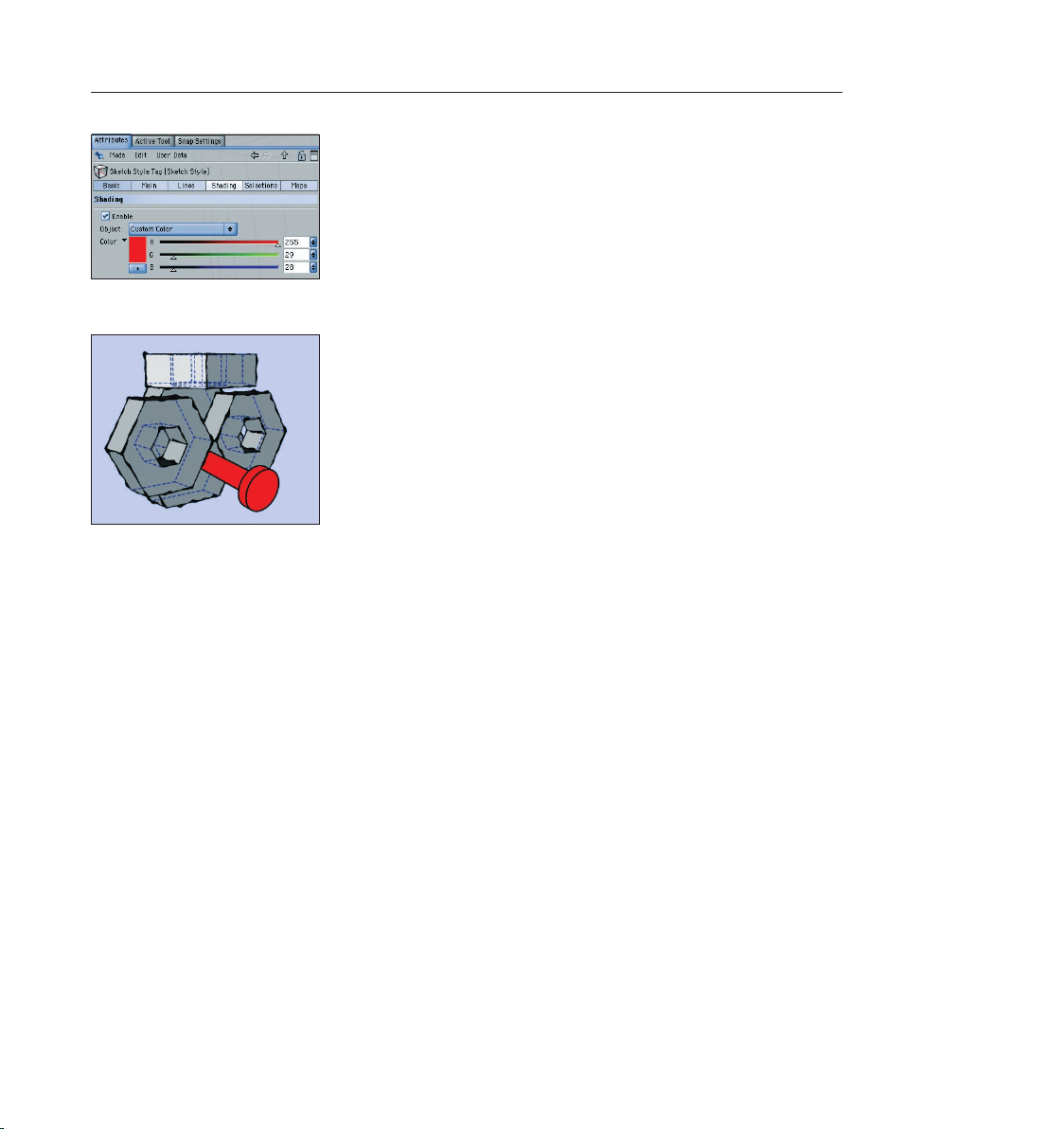
91CINEMA 4D R9 Quickstart – Sketch and Toon
The nose is now red with a black contour.
5. Quick Tutorial – Shaders and Tags
In this tutorial we will combine an object rendered in the sketch mode with an object rendered in
the “normal“ mode in the same scene. We will also examine the “Cel“ shader, one of four special
sketch shaders. Our goal will be to assign different render styles to each of three objects. The
rst object will only have a contour and it should look like it was hand-drawn. We will test the
cel shader on the second object and give it cartoon-like colors. The third object will look like a
normal CINEMA 4D object rendered with standard settings. All of these objects will be depicted
in the scene together.
Start with a new (empty) scene and create three “Figure“ objects. Move the gures a little on the
Z-axis so they are all standing in a row. Rename the gures “Figure_front“, “Figure_center“ and
“Figure_rear“.
Page 100

92 CINEMA 4D R9 Quickstart – Sketch and Toon
93CINEMA 4D R9 Quickstart – Sketch and Toon
Create a new material in the Material Manager (File/New Material). Deactivate the “Color“ and
“Specular“ channels in the “Basic“ menu of the Attributes Manager. Activate “Luminance“ and
switch to the “Luminance“ menu. Click on the small arrow to the right of the word “Texture“.
Select Sketch/Cel.
The cel shader is a type of gradient shader. It can be loaded into any channel but for a
cartoon-like look it should be put into the “Luminance“ channel where its colors will always be
rendered as full-tone and will not be inuenced by the scene’s lighting.
Click on “Cel“. The cel settings will appear. 3 shades of blue are preset here by default but they
don’t really match our gures. Double click on the color sliders and create three new brown-tone
colors.
 Loading...