

Page 1

Thinking Particles
Page 2

Thinking Particles
Programming Team Christian Losch, Philip Losch, Richard Kurz, Tilo Kühn, Thomas Kunert,
David O’Reilly, Cathleen Poppe.
Plugin Programming Sven Behne, Wilfried Behne, Michael Breitzke, Kiril Dinev, Per-Anders Edwards,
David Farmer, Jamie Halmick, Richard Hintzenstern, Jan Eric Hoffmann,
Eduardo Olivares, Nina Ivanova, Markus Jakubietz, Eric Sommerlade,
Hendrik Steffen, Jens Uhlig, Michael Welter, Thomas Zeier.
Product Manager Marco Tillmann.
QA Manager Björn Marl.
Writers Paul Babb, Rick Barrett, Oliver Becker, Jens Bosse, Chris Broeske, Chris Debski,
Glenn Frey, Michael Giebel, Jason Goldsmith, Jörn Gollob, Sven Hauth,
Josiah Hultgren, Arndt von Königsmarck, David Link, Arno Löwecke, Aaron Matthew,
Josh Miller, Matthew ‘Mash’ O’Neill, Janine Pauke, Marcus Spranger, Luke Stacy,
Perry Stacy, Marco Tillmann, Jeff Walker, Scot Wardlaw.
SDK Docs & Support David O’Reilly, Mikael Sterner.
Layout Oliver Becker, Harald Egel, Michael Giebel, David Link, Luke Stacy, Jeff Walker.
Translation Oliver Becker, Michael Giebel, Arno Löwecke, Björn Marl, Josh Miller, Janine Pauke,
Luke Stacy, Marco Tillmann, Scot Wardlaw.
Copyright © 1989-2004 by MA XON Computer GmbH. All rights reserved.
English translation Copyright © 2004 by MAXON Computer Ltd. All rights reserved.
This manual and the accompanying software are copyright protected. No part of this document may be
translated, reproduced, stored in a retrieval system or transmitted in any form or by any means, electronic or
mechanical, for any purpose, without the express written permission of MA XON Computer.
Although every precaution has been taken in the preparation of the program and this manual, MAXON Computer
assumes no responsibility for errors or omissions. Neither is any liability assumed for damages resulting from
the use of the program or from the information contained in this manual.
This manual, as well as the software described in it, is furnished under license and may be used or copied
only in accordance with the terms of such license. The content of this manual is furnished for informational
use only, is subject to change without notice, and should not be construed as a commitment by MAXON
Computer. MAXON Computer assumes no responsibility or liability for any errors or inaccuracies that may
appear in this book.
MAXON Computer, the MAXON logo, CINEMA 4D, Hyper NURBS, and C.O.F.F.E.E. are trademarks of MAXON
Computer GmbH or MAXON Computer Inc. Acrobat, the Acrobat logo, PostScript, Acrobat Reader, Photoshop
and Illustrator are trademarks of Adobe Systems Incorporated registered in the U.S. and other countries. Apple,
AppleScript, AppleTalk, ColorSync, Mac OS, QuickTime, Macintosh and TrueType are trademarks of Apple
Computer, Inc. registered in the U.S. and other countries. QuickTime and the QuickTime logo are trademarks
used under license. Microsoft, Windows, and Windows NT are either registered trademarks or trademarks
of Microsoft Corporation in the U.S. and/or other countries. UNIX is a registered trademark only licensed
to X/Open Company Ltd. All other brand and product names mentioned in this manual are trademarks or
registered trademarks of their respective companies, and are hereby acknowledged.
Page 3

MAXON Computer End User License Agreement
NOTICE TO USER
WITH THE INSTALLATION OF THINKING PARTICLES (THE “SOFTWARE”) A CONTRACT IS CONCLUDED
BETWEEN YOU (“ YOU” OR THE “USER”) AND MAXON COMPUTER GMBH ( THE “LICENSOR”), A COMPANY
UNDER GERMAN LAW WITH RESIDENCE IN FRIEDRICHSDORF, GERMANY.
WHEREAS BY USING AND/OR INSTALLING THE SOFTWARE YOU ACCEPT ALL THE TERMS AND CONDITIONS
OF THIS AGREEMENT. IN THE CASE OF NON-ACCEPTANCE OF THIS LICENSE YOU ARE NOT PERMITTED TO
INSTALL THE SOFTWARE.
IF YOU DO NOT ACCEPT THIS LICENSE PLEASE SEND THE SOFTWARE TOGETHER WITH ACCOMPANYING
DOCUMENTATION TO MAXON COMPUTER OR TO THE SUPPLIER WHERE YOU BOUGHT THE SOFTWARE.
1. General
Under this contract the Licensor grants to you, the User, a non-exclusive license to use the Software and its
associated documentation. The Software itself, as well as the copy of the Software or any other copy you
are authorized to make under this license, remain the property of the Licensor.
2. Use of the Software
You are authorized to copy the Software as far as the copy is necessary to use the Software. Necessary
copies are the installation of the program from the original disk to the mass storage medium of your
hardware as well as the loading of the program into R AM.
(2) Furthermore the User is entitled to make a backup copy. However only one backup copy may be made
and kept in store. This backup copy must be identied as a backup copy of the licensed Software.
(3) Further copies are not permitted; this also includes the making of a hard copy of the program code on a
printer as well as copies, in any form, of the documentation.
3. Multiple use and network operation
(1) You may use the Software on any single hardware platform, Macintosh or Windows, and must decide
on the platform (Macintosh or Windows operating system) at the time of installation of the Software. If
you change the hardware you are obliged to delete the Software from the mass storage medium of the
hardware used up to then. A simultaneous installation or use on more than one hardware system is not
permitted.
(2) The use of the licensed Software for network operation or other client server systems is prohibited if this
opens the possibility of simultaneous multiple use of the Software. In the case that you intend to use the
Software within a network or other client server system you should ensure that multiple use is not possible
by employing the necessary access security. Otherwise you will be required to pay to the Licensor a special
network license fee, the amount of which is determined by the number of Users admitted to the network.
(3) The license fee for network operation of the Software will be communicated to you by the Licensor
immediately after you have indicated the number of admitted users in writing. The correct address of the
Licensor is given in the manual and also at the end of this contract. The network use may start only after
the relevant license fee is completely paid.
Page 4

4. Transfer
(1) You may not rent, lease, sublicense or lend the Software or documentation. You may, however, transfer
all your rights to use the Software to another person or legal entity provided that you transfer this
agreement, the Software, including all copies, updates or prior versions as well as all documentation to
such person or entity and that you retain no copies, including copies stored on a computer and that the
other person agrees that the terms of this agreement remain valid and that his acceptance is communicated
to the Licensor.
(2) You are obliged to carefully store the terms of the agreement. Prior to the transfer of the Software you
should inform the new user of these terms. In the case that the new user does not have the terms at hand
at the time of the transfer of the Software, he is obliged to request a second copy from the Licensor, the
cost of which is born by the new licensee.
(3) After transfer of this license to another user you no longer have a license to use the Software.
5. Updates
If the Software is an update to a previous version of the Software, you must possess a valid licence to such
previous version in order to use the update. You may continue to use the previous version of the Software
only to help the transition to and the installation of the update. After 90 days from the receipt of the
update your licence for the previous version of the Software expires and you are no longer permitted to use
the previous version of the Software, except as necessary to install the update.
6. Recompilation and changes of the Software
(1) The recompilation of the provided program code into other code forms as well as all other types
of reverse engineering of the different phases of Software production including any alterations of the
Software are strictly not allowed.
(2) The removal of the security against copy or similar safety system is only permitted if a faultless
performance of the Software is impaired or hindered by such security. The burden of proof for the fact that
the performance of the program is impaired or hindered by the security device rests with the User.
(3) Copyright notices, serial numbers or other identications of the Software may not be removed or
changed. The Software is owned by the Licensor and its structure, organization and code are the valuable
trade secrets of the Licensor. It is also protected by United States Copyright and International Treaty
provisions. Except as stated above, this agreement does not grant you any intellectual property rights on
the Software.
7. Limited warranty
(1) The parties to this agreement hereby agree that at present it is not possible to develop and produce
software in such a way that it is t for any conditions of use without problems. The Licensor warrants that
the Software will perform substantially in accordance with the documentation. The Licensor does not
warrant that the Software and the documentation comply with certain requirements and purposes of the
User or works together with other software used by the licensee. You are obliged to check the Software
and the documentation carefully immediately upon receipt and inform the Licensor in writing of apparent
defects 14 days after receipt. Latent defects have to be communicated in the same manner immediately
after their discovery. Otherwise the Software and documentation are considered to be faultless. The
defects, in particular the symptoms that occurred, are to be described in detail in as much as you are able
to do so. The warranty is granted for a period of 6 months from delivery of the Software (for the date of
Page 5

which the date of the purchase according to the invoice is decisive). The Licensor is free to cure the defects
by free repair or provision of a faultless update.
(2) The Licensor and its suppliers do not and cannot warrant the performance and the results you may
obtain by using the Software or documentation. The foregoing states the sole and exclusive remedies for
the Licensor’s or its suppliers’ breach of warranty, except for the foregoing limited warranty. The Licensor
and its suppliers make no warranties, express or implied, as to noninfringement of third party rights,
merchantability, or tness for any particular purpose. In no event will the Licensor or its suppliers be liable
for any consequential, incidental or special damages, including any lost prots or lost savings, even if a
representative of the Licensor has been advised of the possibility of such damages or for any claim by any
third party.
(3) Some states or jurisdictions do not allow the exclusion or limitation of incidental, consequential or
special damages, or the exclusion of implied warranties or limitations on how long an implied warranty
may last, so the above limitations may not apply to you. In this case a special limited warranty is attached
as exhibit to this agreement, which becomes part of this agreement. To the extent permissible, any implied
warranties are limited to 6 months. This warranty gives you specic legal rights. You may have other rights
which vary from state to state or jurisdiction to jurisdiction. In the case that no special warranty is attached
to your contract please contact the Licensor for further warranty information.
The user is obliged to immediately inform the transport agent in writing of any eventual damages in transit
and has to provide the licensor with a copy of said correspondence, since all transportation is insured by
the licensor if shipment was procured by him.
8. Damage in transit
You are obliged to immediately inform the transport agent in writing of any eventual damages in transit
and you should provide the Licensor with a copy of said correspondence, since all transportation is insured
by the Licensor if shipment was procured by him.
9. Secrecy
You are obliged to take careful measures to protect the Software and its documentation, in par ticular the
serial number, from access by third parties. You are not permitted to duplicate or pass on the Software or
documentation. These obligations apply equally to your employees or other persons engaged by you to
operate the programs. You must pass on these obligations to such persons. You are liable for damages in all
instances where these obligations have not been met. These obligations apply equally to your employees or
other persons he entrusts to use the Software. The User will pass on these obligations to such persons. You
are liable to pay the Licensor all damages arising from failure to abide by these terms.
10. Information
In case of transfer of the Software you are obliged to inform the Licensor of the name and full address of
the transferee in writing. The address of the Licensor is stated in the manual and at the end of this contract.
11. Data Protection
For the purpose of customer registration and control of proper use of the programs the Licensor will store
personal data of the Users in accordance with the German law on Data Protection (Bundesdatenschutzg
esetz). This data may only be used for the above-mentioned purposes and will not be accessible to third
parties. Upon request of the User the Licensor will at any time inform the User of the data stored with
regard to him.
Page 6

12. Other
(1) This contract includes all rights and obligations of the parties. There are no other agreements. Any
changes or alterations of this agreement have to be performed in writing with reference to this agreement
and have to be signed by both contracting parties. This also applies to the agreement on abolition of the
written form.
(2) This agreement is governed by German law. Place of jurisdiction is the competent court in Frankfurt
am Main. This agreement will not be governed by the United Nations Convention on Contracts for the
International Sale of Goods, the application of which is expressly excluded.
(3) If any part of this agreement is found void and unenforceable, it will not affect the validity of the
balance of the agreement which shall remain valid and enforceable according to its terms.
13. Termination
This agreement shall automatically terminate upon failure by you to comply with its terms despite being
given an additional period to do so. In case of termination due to the aforementioned reason, you are
obliged to return the program and all documentation to the Licensor. Furthermore, upon request of
Licensor you must submit written declaration that you are not in possession of any copy of the Software on
data storage devices or on the computer itself.
14. Information and Notices
Should you have any questions concerning this agreement or if you desire to contact MA XON Computer for
any reason and for all notications to be performed under this agreement, please write to:
MAXON Computer GmbH
Max-Planck-Str. 20
D-61381, Friedrichsdorf
Germany
or for North and South America to:
MAXON Computer, Inc.
2640 Lavery Court Suite A
Newbury Park, CA 91320
USA
or for the United Kingdom and Republic of Ireland to:
MAXON Computer Ltd
The Old School, Greeneld
Bedford MK45 5DE
United Kingdom
We will also be pleased to provide you with the address of your nearest supplier.
Page 7

Contents
Introduction........................................................................................................................................... 1
Overview................................................................................................................................................ 3
1 Settings ..............................................................................................................7
General tab ............................................................................................................................................ 7
Channels tab........................................................................................................................................ 10
Particle Geometry object ..................................................................................................................... 10
Network rendering .............................................................................................................................. 11
2 Nodes ...............................................................................................................15
TP Initiator Group ................................................................................................................................ 15
PPass ............................................................................................................................................... 15
PPass AB .......................................................................................................................................... 16
TP Condition Group ............................................................................................................................. 19
PAge................................................................................................................................................ 19
PLight.............................................................................................................................................. 20
TP Generator Group............................................................................................................................. 23
PBlurp ............................................................................................................................................. 23
PBorn .............................................................................................................................................. 28
PDraw ............................................................................................................................................. 30
PFragment ...................................................................................................................................... 33
PMatterWaves................................................................................................................................. 37
PStorm ............................................................................................................................................ 47
TP Standard Group .............................................................................................................................. 52
PAlignment ..................................................................................................................................... 52
PDie................................................................................................................................................. 54
PGroup............................................................................................................................................ 55
PMass.............................................................................................................................................. 55
PRolling ........................................................................................................................................... 57
PScale.............................................................................................................................................. 58
PSetData ......................................................................................................................................... 60
PShape ............................................................................................................................................ 62
PSize................................................................................................................................................ 64
PSpin ............................................................................................................................................... 65
TP Dynamic Group ...............................................................................................................................68
PBubble........................................................................................................................................... 68
PDeector ....................................................................................................................................... 69
PFreeze............................................................................................................................................ 73
Page 8

PFriction.......................................................................................................................................... 74
PGravity .......................................................................................................................................... 76
PMotionInheritance ........................................................................................................................ 78
PPositionFollow ..............................................................................................................................80
PRepulse&Bounce ........................................................................................................................... 82
PVelocity ......................................................................................................................................... 83
PWind ............................................................................................................................................. 85
TP Helper Group .................................................................................................................................. 88
PChronometer ................................................................................................................................ 88
PGetData ........................................................................................................................................ 89
PGroup............................................................................................................................................ 90
PSpinConvert .................................................................................................................................. 90
PSurfacePosition ............................................................................................................................. 91
PTimer............................................................................................................................................. 93
PVelocityConvert ............................................................................................................................ 95
PVolumePosition ............................................................................................................................. 96
3 Tutorials.......................................................................................................... 101
Introduction....................................................................................................................................... 101
Combining Thinking Particles with XPresso ...................................................................................... 103
Using Thinking Particles with PyroCluster ..........................................................................................117
Deforming Particles ........................................................................................................................... 121
Working with Particle Groups ........................................................................................................... 123
Index.................................................................................................................. 143
Page 9

THINKING PARTICLES
INTRODUC TION 1
Introduction
Create amazing particle effects
with Thinking Particles, the
node-based particle system that
gives you complete control over
each and every particle.
Thank you for purchasing Thinking Particles, the CINEMA 4D module that makes it easy
to control every aspect of particle motion. With Thinking Particles you can emit particles
from any point, edge or polygon, collide particles with objects and other particles,
achieve lifelike motion with forces such as gravity and wind that take the mass and
size of particles into account, spawn and fragment particles and much more.
This manual is divided into a tutorial section and a reference section. Thinking Particles
has dozens of powerful nodes that will require some exploring, so in order to get a
feel for Thinking Particles we recommend that you work through the tutorials and,
if something isn’t clear, look it up in the reference for a full description.
If you are impatient and want to get started straightaway then we recommend that you
read the PStorm node section in the reference rst. Look up ‘PStorm’ in the index.
As a node-based particle system, Thinking Particles may feel strange at rst. However,
with a little time and effort, you’ll soon feel right at home as you learn how to control
particles with the precision of a Swiss watchmaker.
Registration
Registering your Thinking Particles module is extremely important. The serial number
included with your Thinking Particles package is temporary and will expire three months
after the module’s installation. To receive your nal serial number, you must register.
So please ll in and return the registration form at the earliest opportunity.
Registering your Thinking Par ticles module will also entitle you to technical
support via telephone, fax and email. And, by checking the appropriate box on the
registration form, MA XON will keep you informed of the latest product information
and updates.
You can also register online at register.maxon.net.
Installation
To install Thinking Particles, run the installation program and follow the on-screen
installation instructions.
The installation program will create a ThinkingParticles folder in your CINEMA 4D
Modules folder. The installation program will place all the CINEMA 4D Thinking
Particles les into this ThinkingParticles folder.
Training
Training is available for Thinking Particles and other MAXON products. For details,
please contact MAXON or your local MAXON distributor.
Page 10

2 INTRODUC TION
THINKING PARTICLES
Web Resources
Thousands of powerful resources are available on the web, including online tutorials,
discussion lists, textures, models, galleries and information on 3D books. You’ll nd
links to a rich selection of these sites at www.maxon.net, MAXON’s homepage.
One website that you may wish to bookmark is www.plugincafe.com, the home
of CINEMA 4D plugins. Here you will nd dozens of useful plugins, both free and
commercial. For plugin developers, there are resources, including the SDK, tutorials
and a free support forum.
Lastly, there is the MAXON website itself: www.maxon.net. In addition to the links
mentioned above, it is from here that you can register your MAXON product, download
updates, send MAXON a suggestion, check out the gallery, learn from online tutorials
and much more.
Technical Support
Your local MAXON distributor will be delighted to assist you with your technical queries
for Thinking Particles. You are also welcome to contact MAXON directly.
Please note that you will be entitled to technical support provided you have registered
your Thinking Particles module (see Registration, above).
Page 11

THINKING PARTICLES
OVERVIEW 3
Overview
Thinking Particles is a rulebased particle system that
offers tremendous power
and exibility, but there
is no doubt that it will
take some time for you to
understand how to use the
package. For any particular
job there will be many
different approaches and a
number of solutions.
Here is a brief overview of Thinking Particles that should help to get you started.
Please read this and then work through the tutorials – the time spent will be well
worth it.
Thinking Particles is node -based and uses the CINEMA 4D XPresso Editor for the
creation and editing of its various nodes; so please ensure that you understand how
to use XPresso before proceeding. The other concept to master is that, once a particle
has been born from an emitter, the emitter no longer has any control of it. That’s
why it is important to group particles together so that you can then apply further
rules and operations to the group.
OK, so rst to generate some particles – you do this with the PStorm or PBorn nodes.
PStorm has many inbuilt parameters which means that you can give the particles speed,
size etc. straightaway; once you have created a PStorm node you will see particles
in the viewport. PBorn is simpler and you will need to apply some other rules to its
particles before you can use them; you can do this with, say, the PSetData node.
Unless you have created a new group for your particles (see ‘Particle Groups’ on
page 9) they will be placed in the All group (not really a group but the root of the
particle tree).
Now you can add other rules (nodes) into your particle system to affect the particles;
the rules are organized under headings like TP Condition (apply conditions such as
age), TP Standard (for particle shape, size, mass etc.), TP Dynamic (effects such as
gravity and wind) and others. Every node will affect the particle stream attached to
its input port – you can see how important it is to group particles.
So it is easy to, say, give your particles shape by associating them with CINEMA 4D
objects using the PShape node, or to affect them with gravity (give them weight and
use a PGravity node) or have them collide with one another (use the PRepulse&Bounce
node). Connect nodes via wires between their ports, as explained in the XPresso
section of the CINEMA 4D Reference Manual.
Finally, please remember to plan ahead and try things out before committing yourself
to a large, complex set-up. Also, keep in mind that adding shape to your particles will,
naturally, slow down the viewport display speed, so it’s best to experiment before
adding shape to your particles.
Page 12

Page 13

1 Settings
Page 14

Page 15
THINKING PARTICLES
SETTINGS 7
Settings
To unleash the power of
Thinking Particles, you’ll
frequently need to use particle
groups. This is the place to create
them. In addition, you can dene
global and local settings for the
groups, including how a group’s
particles are represented in the
viewport.
Choose how par ticle s are
represented in the v iewpo rt
and whe ther ob ject s used as
particles a re shown. On the
General tab yo u’ll als o nd
information s uch as the total
numbe r of particle s and the
numbe r of particle s in each
group at the curr ent fra me.
To take full advantage of the power of Thinking Particles you should always try to
work with particle groups. Particle groups enable you to achieve extraordinary control
over your particle effects.
For example, suppose you have created a shoal of sh from a single emitter and these
sh are swimming together. Suddenly predators arrive on the scene and you want
to separate the shoal into two smaller shoals that dart away in opposite directions.
Particle groups give you an easy way to achieve this.
Assign half of the sh to one particle group, the other half to another group, then
send the groups in opposite directions. This is just one simple example of the countless
uses of particle groups. Whenever you want to treat some particles differently to
others, you probably need to use particle groups. The Thinking Particles Settings is
where you create these groups.
In the Thinking Particles Settings, you can also check information such as the total
number of particles in a particular group at the current frame, or change how particles
are displayed in the viewport and more.
To access the Thinking Particles Settings:
- From the main menu, choose Plugins > Thinking Particles > Thinking Particles
Settings.
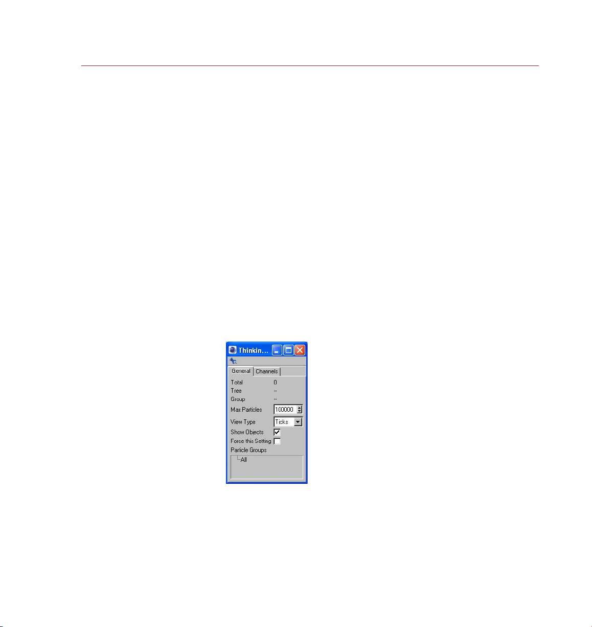
General tab
Total
The number of particles that exist at the current frame — a total count of all the
particles in all of the groups.
Page 16

8 SETTINGS
THINKING PARTICLES
Tree
The number of particles in the currently selected branch of the particle tree. A branch
is a hierarchical level within the Thinking Particles group system. See also ‘Particle
Groups’, below.
Group
Shows the number of particles that currently belong to the selected group. See also
‘Particle Groups’, below.
Max Particles
Denes the maximum number of particles that can be generated. This setting
helps you to prevent situations where you accidentally create so many particles
that your computer system simply cannot cope with them all!
View Type
This parameter is a global setting that controls how the particles are represented in
the viewport. The particles can be shown as akes, dots, ticks, drops, boxes or they
can be hidden.
The View Type setting has no affect on how the particles will look when rendered. It is
purely a visual aid to help you recognize the particles in the viewport. However, each
particle group has its own settings and may use a different view type to override this
global value. For more information on these settings, see ‘Particle Groups’, below.
Show Objects
Enable this option if you have used an object for particles and you want the particle
objects to be shown in the viewport. Keep in mind that hundreds of complex objects
may slow down the viewport’s refresh rate. This value is a global one that may be
overwritten using settings of each particle group. For more information on these
local settings, see ‘Particle Groups’, below.
Force This Setting
Each particle group has its own display settings that usually override the global View
Type and Show Objects settings described above. However, sometimes it can be useful
to force all particle groups to use the global settings.
For example, suppose your scene has 20 particle groups, each with its local Show
Object setting enabled (you access these local options by choosing Settings from the
particle group’s context menu). To speed up the viewport’s refresh rate, you decide to
hide the particle objects. Although you could disable Show Object for each particle
group, it’s quicker to disable the global Show Objects setting and enable Force This
Setting. All groups will then be forced to use the global value.
Page 17
THINKING PARTICLES
SETTINGS 9
Particle Groups
To get the most out of Thinking Particles it is important to plan ahead, consider how
all your particles are going to interact and, above all, assign different sets of particles
to different particle groups — this way you will build in exibility, which can save a
great deal of time should you decide to change things later.
The Particle Groups pane is where you add and remove particle groups, sort them
and edit their local settings. The All group is created automatically. By default, all
particles are assigned to the All group.
The groups are arranged in a hierarchy that works in the same way as CINEMA 4D’s
XPresso manager. The advantage of this structure is that you can build an entire tree
of groups, the top-most of which will contain all the groups belonging to that branch
and thus the particles of these groups also.
To add a new particle group, in the Particle Groups pane, right-click (Windows) or
Command-click (Mac OS) on the All group (or any other group if present) and choose
Add from the context menu that appears.
The new group will be created and placed below the group in the hierarchy that you
called the context menu from. New groups are named ‘Group’ followed by a number.
We recommend that you rename the groups to names that are more meaningful and
less likely to be confused with other group names. To rename a group, double-click
its name, enter the new name into the dialog that opens and click OK.
You can rearrange the hierarchy by dragging and dropping groups. To delete groups,
select them (Shift-click to add a group to the selection), right-click (Windows) or
Command-click (Mac OS) one of the groups and choose Remove from the context
menu that appears. Keep in mind that all sub-groups of the selected groups will be
deleted as well. Particles belonging to the deleted groups will be transferred to the
All group.
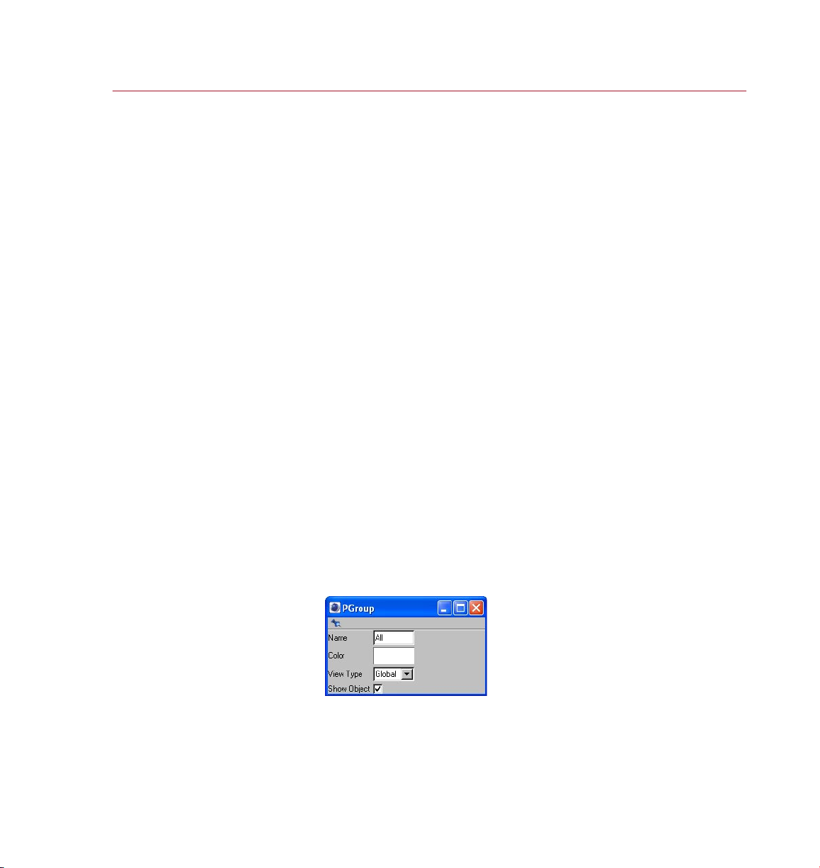
Each particle group has local
sett ings to de ne thi ngs suc h as
the color of the gr oup’s par ticl es
in the viewpor t and wh ether
particle objects are show n.
Settings
Each particle group has its own settings. To access these settings, in the Particle
Groups pane, right-click (Windows) or Command-click (Mac OS) the name of the
desired group and choose Settings from the context menu.
Page 18
10 SETT INGS
THINKING PARTICLES
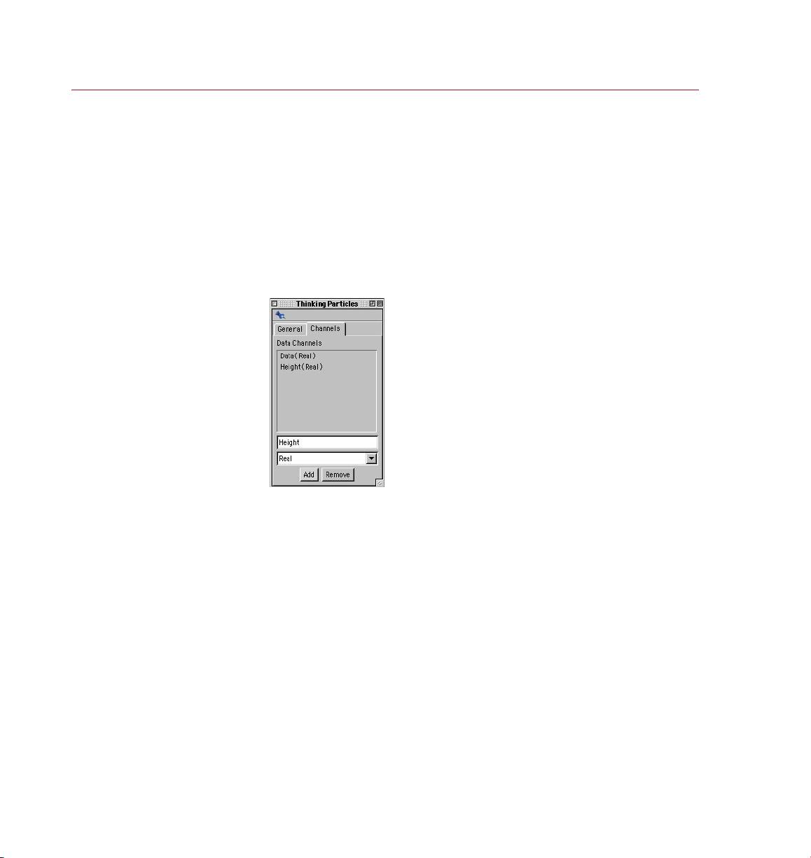
Here yo u can create dat a
channels that will enable you
to pass custom va lues to the
Think ing Par ticle s expr essio n.
In these settings, you can set a local value for the View Type and Show Object
setting. For information on these two settings, see ‘View Type’, ‘Show Objects’
and ‘Force This Setting’ above.
In addition, here you can rename the group and change the color used to display
the particles in the viewport. This is useful when working with multiple groups. By
assigning different colors to each group, you can soon tell which particles belong
to which group directly in the viewport. To change the color, click the Color box
and set the color system dialog that opens to the desired color. This does not affect
the color of the rendered particles!
Channels tab
You can pass your own data to a Thinking Particles effect via data channels. These
operate in the same way as the user data ports of XPresso expressions.
You can add data channels as ports to P Get Data nodes and P Set Data nodes.
The data types available are the same as those for XPresso – please refer to your
CINEMA 4D reference manual for a description of these data types. To remove a
channel from the list, select the channel and click Remove.
You can also use XPresso’s user data ports to pass values to the expression.
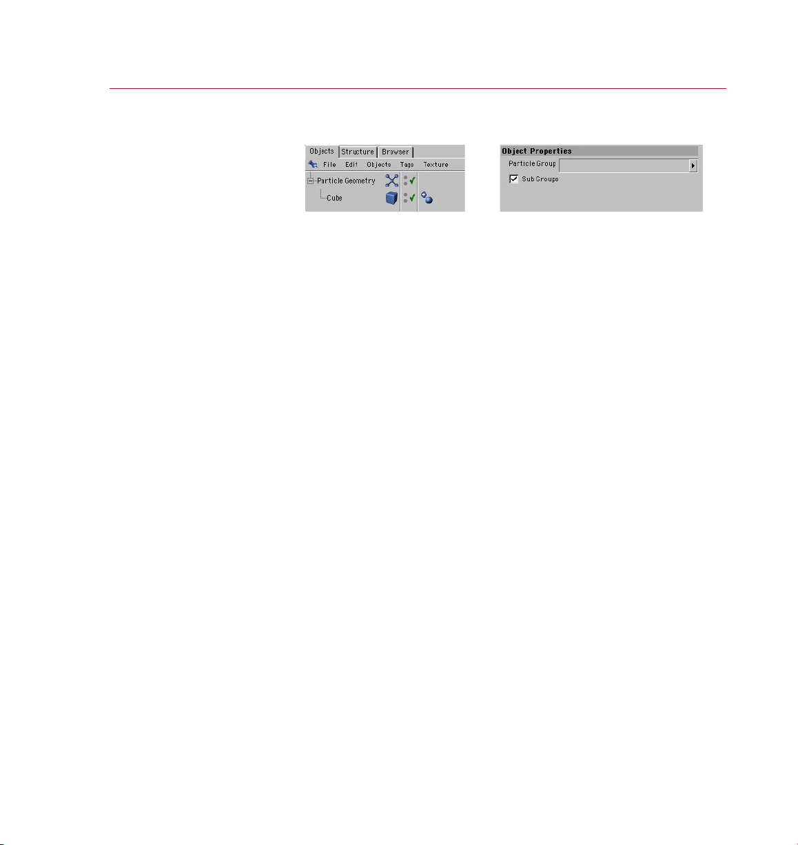
Particle Geometry object
The Particle Geometry object is needed if you are going to use objects as particles.
Any object that you want to use as particles must be a below a Particle Geometry
object in the hierarchy of the Object manager; it can either be a child of the Particle
Geometry object or simply below it in the hierarchy.
Page 19
THINKING PARTICLES
SETTINGS 11
The obj ect that you want t o use
Parti cle Geometr y obje ct in the
To create a Particle Geometry object, from the main menu, choose Plugins > Thinking
Particles > Particle Geometry.
as par ticle s must be b elow a
Objec t manager.
When the Particle Geometry object is selected, its settings will be displayed in the
Attribute manager (see above). Drag the name of any particle group from the Thinking
Particles Settings and drop it into the Particle Group box. If Sub Groups is enabled,
the sub-groups of the chosen object will also be assigned to the particle group.
Network rendering
When rendering a Thinking Particles scene over a network using the optional
CINEMA 4D NET Render module, the rendering may take longer than if you were to
render the scene on a single computer!
This happens when there are complex interactions between the particles, since the
complete interaction of the particles must be calculated from frame to frame. In such
cases, adding more machines to the network may slow down the render time further
still, especially when mixing fast computers with slower ones. Avoid rendering these
types of scenes over a network.
Page 20

Page 21

2 Nodes
Page 22

Page 23
THINKING PARTICLES
NODES 15
Nodes
Nodes are the building blocks of
your Thinking Particles effect.
The nodes are arranged by group
according to their function.
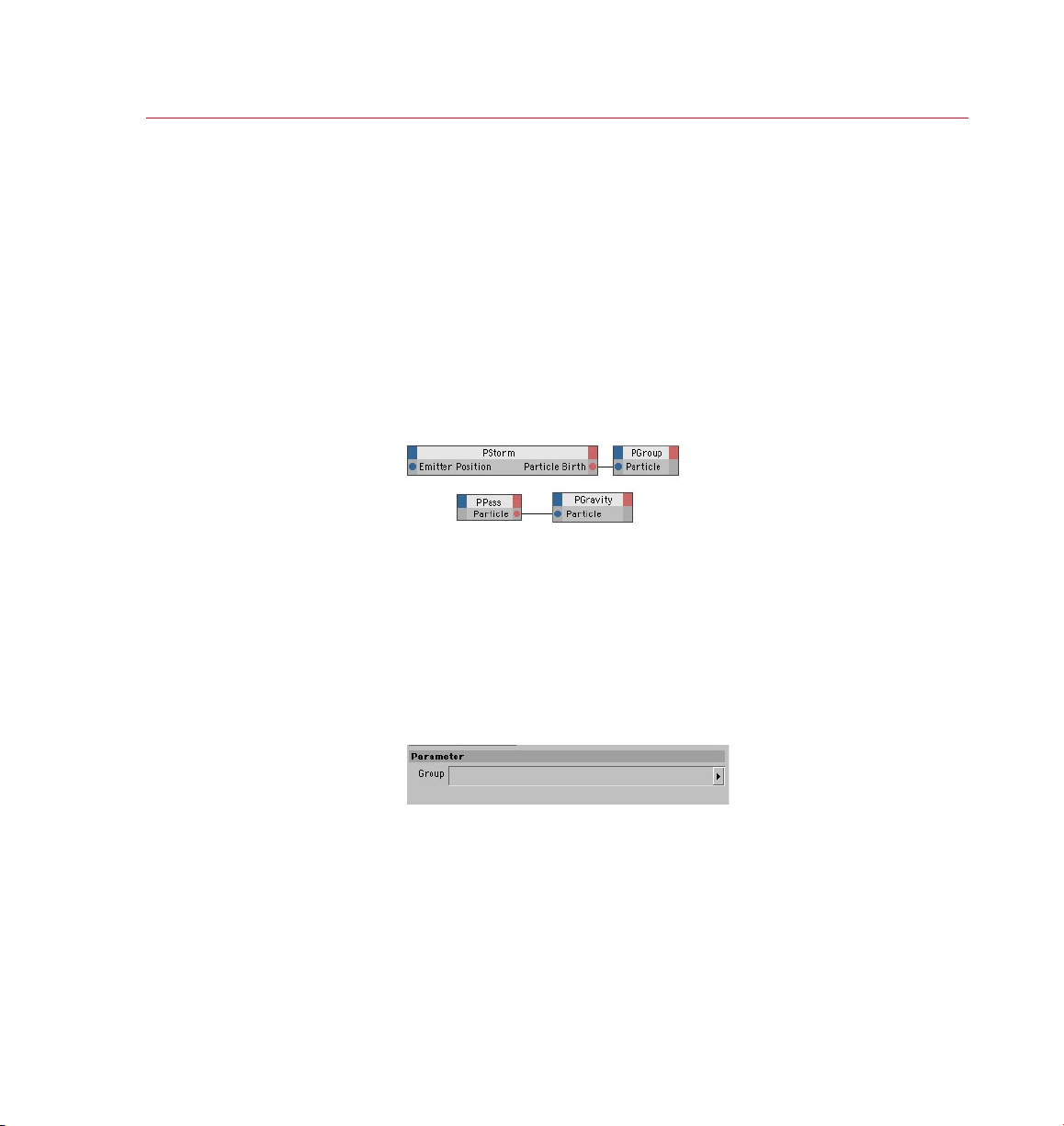
To add a gravitational forc e to
particles , group the particles
and use PPass to pass the group
to a PGrav ity no de.
Thinking Particles makes use of CINEMA 4D’s XPresso system. The XPresso Editor is
the place to create and edit your Thinking Particles effects.
Nodes are the building blocks of Thinking Particles effects. To create a node, in the
XPresso Editor, right-click (Windows) or Command-click (Mac OS) and choose the
node’s name from the New Node > Thinking Particles menu. On this menu, the nodes
are arranged by group according to their function.
In this chapter you’ll nd a description of each Thinking Particles node, listed by group
and then by order of appearance on the menu. For general information on using nodes
and the XPresso Editor, please refer to your CINEMA 4D Reference Manual.
TP Initiator Group
PPass
This frequently-used node allows you to pass a group of particles to another node.
PPass is used to control which particle groups have which effects applied to them.
For example, suppose you want to apply gravity to a particular group of particles.
In this case you would rst assign the group to a PPass node and then connect the
PPass node’s Particle output to the Particle input of a PGravity node.
To learn how to create particle groups, see ‘Particle Groups’ earlier in this
chapter or work through the tutorials.
Choose which group of pa rtic les
the nod e should output .
Attribute manager settings
Group
To choose which group of particles the node should output, drag the name of the
desired group from the Thinking Particles settings (XPresso Editor: Custom > Thinking
Particles > Settings) and drop it into this box.
Page 24
16 NODES
THINKING PARTICLES
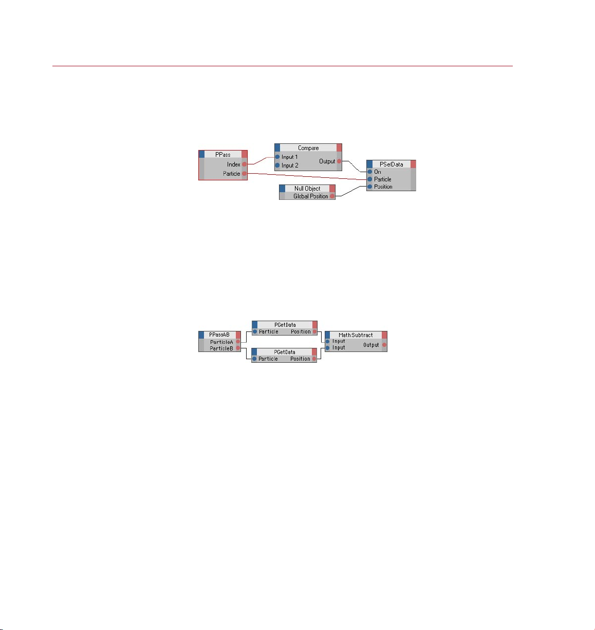
Suppose you want to set the
position of the 3 0th par ticl e
creat ed to the s ame pos ition as a
Null object . Use the node setup
shown here and s et the Co mpare
node’s Fu nctio n to ‘==’ and
You can use P PassA B to compare, say, the
positions of pa rtic les in t wo groups. In
this ex ample PPassA B passe s two groups
of particle s to PGet Data wh ich gets
the par ticles’ pos itions; thes e are the n
subtra cted one from the other.
Input 2 to 30.
Output ports
Index
The index number of the particle passed. This is especially useful when creating
particles in Shot mode.
Particle Count
The number of particles passed by the node.
Particle
Connect this port to the Particle input port of the node that should receive the group
of particles.
PPass AB
This node is similar to the PPass node except that it enables you to pass two groups
of particles to other nodes instead of just one group. This is especially useful when
you want to compare the particles in one group with the particles in another, as
illustrated above. You could alternatively use two PPass nodes but this is simpler.
PPassAB is essential when controlling the PRepulse&Bounce node.
To learn how to create particle groups, see ‘Particle Groups’ earlier in this
chapter or work through the tutorials.
Page 25
THINKING PARTICLES
NODES 17
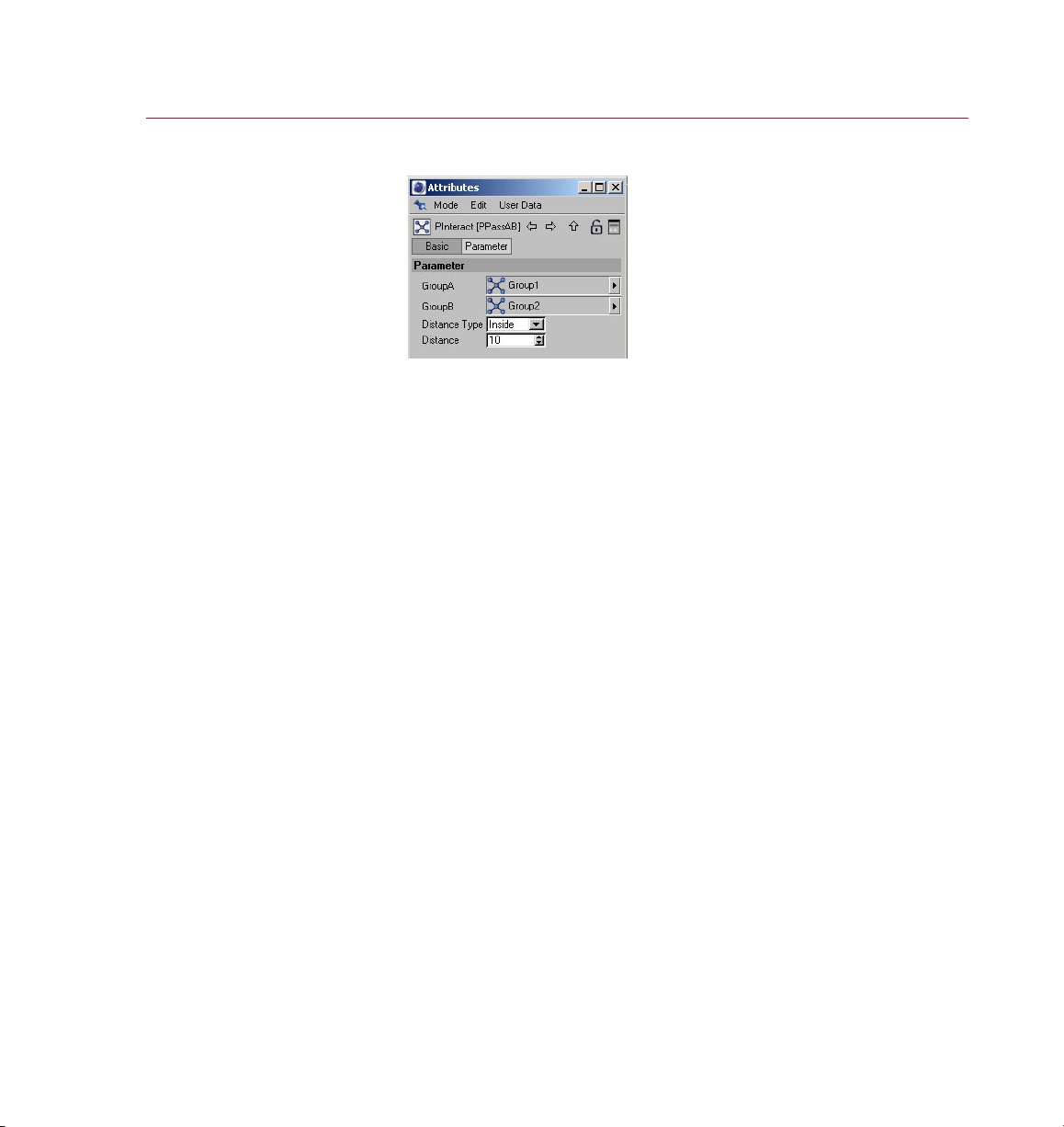
Choose which t wo grou ps
of particle s the node should
output.
Attribute manager settings
GroupA , GroupB
These boxes dene which particle groups the node should output. Open the Thinking
Particles Settings and, from there, drag the name of one of the particle groups and
drop it into the GroupA box. Drag-and-drop the name of the other par ticle group
into the GroupB box.
Distance Type, Distance
These settings allow you to check the distances between particles of the two
groups. The Distance Type setting controls whether the particles will be passed to
the Particle A and Particle B outputs port and if so, when they will be passed.
None
Distances are not checked.
Inside, Outside
Particles in groups A and B are passed to the output ports if they are closer to each
other (type set to Inside) or further apart from each other (type set to Outside)
than the Distance value.
Output ports
Distance AB
The distance between the particles in groups A and B.
Particle Count A , Particle Count B
The current number of particles of A and B.
Particle A, Particle B
Connect each of these ports to the Particle input port of the two nodes that should
receive the particle groups.
Page 26

18 NODES
THINKING PARTICLES
Position A, Position B
The positions of the particles.
Vector AB
The vector between the particles in groups A and B.
Page 27
THINKING PARTICLES
NODES 19
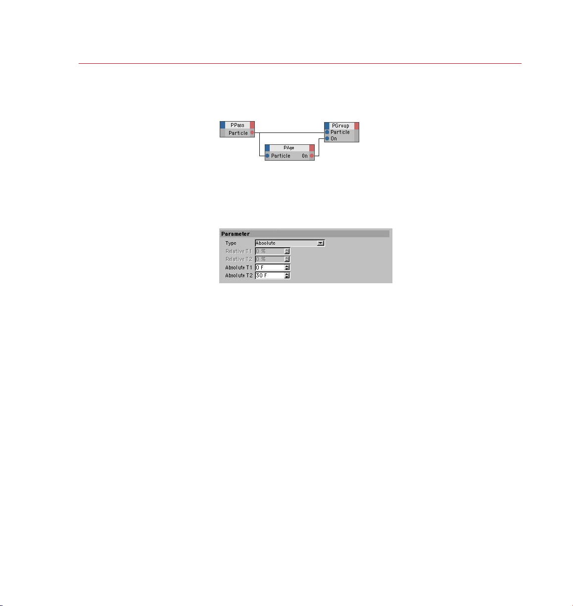
Here we u se PAge to pass only cert ain
particles into a new pa rtic le grou p. For
examp le, we could use A bsolute with
T1=30 and T2=45 so t hat only parti cles
aged be tween 30 and 45 f rames w ill be
passe d into the n ew grou p.
Choose the type of even t that
should be chec ked. For example,
you can c heck wh ich par ticl es
have jus t been born.
TP Condition Group
PAge
This node enables you to check the age of particles or nd out which particles have
just been born, have just died or have just changed groups. The node is mostly used
for putting particles of a certain age into a new group, as illustrated above.
Attribute manager settings
Type, Relative T1/T2, Absolute T1/ T2
Set Type to the type of check that should be performed.
Born, Die
These settings check which particles have been born or have died respectively
during the current frame.
Enters Group
Checks which particles have entered a particular group during the current frame.
Relative
Checks which particles are aged between the two limits dened by Relative T1 and
Relative T2. These limits are specied as percentages, where 0% equals the time
of the particle’s birth and 100% is the time of its death.
Absolute
Checks which par ticles are aged between the limits Absolute T1 and Absolute T2,
which are measured in frames.
Page 28
20 NODES
THINKING PARTICLES
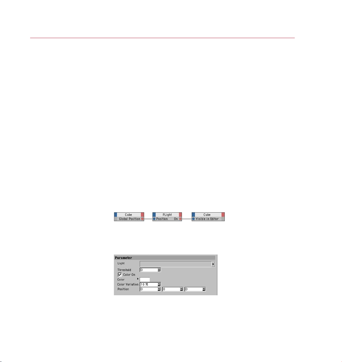
Here we u se a PLig ht node in such a way
that when the color of its associated
light ob ject r eaches more than 90% red
the Cube i s made vi sible in the viewpor t.
There are many other, rath er more u seful,
ways of using PLight.
Additional input ports
Animation Time
Since the node’s parameters can be keyframe animated, by default the CINEMA 4D
time is used internally to ensure that the values are interpolated correctly. However,
you can pass your own time value to this port. Its data type should be Time, which is a
Real number in the simplest case. If no value is passed, CINEMA 4D’s time is used.
Particle
Connect this port to the particle stream that you want to check, such as to the Particle
output port of a PPass node or a PStorm node.
Output port
On
This port outputs a Bool value for each particle to indicate the result of the check — True
if the check was positive, or False if the check was negative. For example, suppose
Type is set to Born, three particles have been born during the current frame and 100
particles already existed before this frame. The node will output False for each of the
100 particles that already existed and True for each of the three new particles.
The most common use of the On port is for placing particles of a particular age into
a new group (connect the On input port of a PGroup node).
PLight
Using this node, you can control actions using a light source’s color or intensity, or
you can check a light’s color, intensity and more at a specied point in 3D space.
Here yo u can choose, am ong
other t hings, which li ght
intensity or c olor sh ould trigger
an acti on.
Attribute manager settings
Light
To choose which light the node will test, drag and drop the light’s name into this
box.
Page 29

THINKING PARTICLES
NODES 21
Threshold
With the help of this value, you can use the PLight node to control actions based on
the brightness of a light source at a particular position in 3D space (dened by the
Position values).
The node outputs a Bool value of either True or False depending on whether the
light’s intensity exceeds the Threshold value at this position in 3D space. The node’s
On port outputs the value False if the light’s brightness is less than or the same as
the Threshold, or True if it exceeds the Threshold. A Threshold of 1 equals a light
intensity of 100%.
For example, suppose you want a PStorm node to emit particles only when a light’s
intensity exceeds 50% at the world coordinates 200,10,-50. In this case, you would
create a PLight node, drag and drop the name of the light into the Light box, set the
Position values to 200,10,-50 and the Threshold value to 0.5 (0.5 x 100 = 50%). You
would then connect the PLight node to the PStorm node via their On ports.
Color On, Color, Color Variation
If you want to control actions based on the color of a light source at a particular
position in 3D space (dened by the Position values), enable Color and set Threshold to
0 (if you don’t set the Threshold to 0, the light’s brightness will be evaluated also).
The node will output a Bool value of True or False depending on whether the light’s
color is the same as (or similar to, depending on the Color Variation setting) the color
dened by the Color setting at this position in 3D space. The node’s On port outputs
True if the two colors are the same/similar, otherwise it gives the value False.
The Color Variation setting denes how similar — dened as a percentage — the light’s
color and the Color setting must be in order to produce a True value. For example,
with a value of 0%, the colors must match exactly in order to produce an output of
True, while a value of 100% means the colors will match regardless.
If you want to control actions based on a light’s color and brightness, in addition set
the Threshold value to the desired brightness. See ‘Threshold’, above. The node’s On
port will then only output the value True if the light’s brightness exceeds the Threshold
value and the light’s color is the same /similar color as the Color setting.
Position
This value denes position at which the light’s value(s) should be checked.
Normal
A normal is a directional vector with a length of 1, which is often used to help calculate
the shading of a polygon surface. A normal can be passed to this port in order to
inuence the light intensity at a given position.
Page 30

22 NODES
THINKING PARTICLES
If no vector is present, a normal that points towards the light source will be generated
automatically. The light will thus fall orthogonally (at right-angles) onto the virtual
surface and will therefore be at its maximum brightness.
Keep in mind that a normal pointing towards the light rays themselves, rather than
at the light object, will cause the light to shine onto the backface of a surface. Thus
an intensity of 0 may result, even if the light illuminates the exact given position.
Additional input ports
Animation Time
Since the node’s parameters can be keyframe animated, by default the CINEMA 4D time
is used internally to ensure that the values are interpolated correctly. However, you can
pass your own time value to this port. This should be of the data type Time, which is a
Real number in the simplest case. If no value is passed, CINEMA 4D’s time is used.
Output ports
Color
Outputs the RGB color of the light at the position dened by the Position values.
Direction
Outputs the directional vector between the light’s position and the position dened
by the Position values. This vector can also be calculated manually by subtracting the
light’s position from the Position values.
Intensity
Outputs the brightness of the light as a Float value at the position dened by the
Position values. An Intensity value of 0 represents 0% brightness, a value of 1
represents 100% brightness.
On
Outputs a Bool value of either True or False depending on the light’s brightness
and/or color at a particular position in 3D space (dened by the Position values). See
‘Threshold’ and ‘Color On, Color, Color Variation’ above.
Page 31

THINKING PARTICLES
NODES 23
TP Generator Group
PBlurp
The PBl urp nod e can mor ph one
shape into anot her.
This node breaks up an object into fragments, moves the fragments along a path,
then reassembles (morphs) them to form a completely new object (the target
object). For example, you can morph the 3D text ‘Thinking’ into ‘Particles’.
Using the PBlurb node
To morph one object into another using the PBlurb node:
- Drag-and-drop two objects into the PBlurb node’s Objects list in the Attribute
manager. For both these objects, set Remaining Type to Hollow. In most cases,
you should hide these objects.
- Create a Particle Geometry (Plugins > ThinkingParticles > Particle Geometry).
- Animate the PBlurb node’s Animation Phase parameter. For example, at
frame 0, record an Animation Phase value of 0%, and at frame 60, record an
Animation Phase value of 100%.
Input Ports
Animation Phase
This input port controls the progress of the morphing effect. A value of 0% means
the original object is fully intact, a value of 100% means the morphing is complete
and the target object has been fully assembled from the fragments.
Animation Time
Since the node’s parameters can be keyframe animated, by default the CINEMA 4D time
is used internally to ensure that the values are interpolated correctly. However, you can
pass your own time value to this port. This should be of the data type Time, which is a
Real number in the simplest case. If no value is passed, CINEMA 4D’s time is used.
On
The On input port takes a Bool value that enables (True) or disables (False) the
node. The node is enabled automatically if you do not add this port.
Output ports
Fragment Count
The number of fragment produced by the node.
Page 32

24 NODES
THINKING PARTICLES
The parameters on this page
allow yo u to choose which
objec ts sho uld be used as
shape s in the morph. You can
also adjust many aspec ts of th e
effe ct suc h as the shape of the
path taken.
Fragment Number
The internal number of the fragment particle currently being generated.
Fragment Particle
Outputs the fragment particles that are currently moving between the objects.
Using this port they can be assigned to individual particle groups or shapes.
Remaining Count
The object is fragmented gradually. This port outputs the number of fragments yet
to be created.
Remaining Number
Outputs the internal numbers of all the remaining fragment particles.
Remaining Particle
Outputs the fragment particles that have not yet been created and are not yet
moving towards the next object.
Attribute manager settings
Objects
In the Object manager, drag the objects that should decay into fragments or be
formed from the fragments and drop them into this box. These objects must be
polygon objects. Primitive objects must be converted to polygons before being
used with this node.
Page 33

THINKING PARTICLES
NODES 25
You can use two or more objects. These can be completely different shapes if you
wish and they can have a different number of polygons. The top-most object in
the Objects list will be used as the starting shape for the effect. This object will
then fragment and morph into the second object in the list, which in turn will
fragment and morph into the third object (if present), and so on.
A spline curve is used to control the path between the objects. Each object has
virtual tangents which you can adjust to control this curve. The Left Tangent and
Right Tangent parameters dene the length of each tangent arm. There is a further
way to control the spline curve: you can add Null objects to the Objects list. Using
these nulls, you can adjust the course of the spline between two polygon objects
(the positions of the nulls will adjust the shape of curve).
The other Attribute manager settings
You can set the following parameters separately for each object in the Objects list.
Select an object and adjust its parameters as desired.
Stay
By default, the time it takes an object to break up into fragments is the same as
the time it takes for the fragments to form the next object. However, if you set
Stay to a value higher than 0%, the decay into fragments will be delayed.
A value of 100% corresponds to the length of time an object needs to decay into
another object. Therefore if you increase the Stay value, the object will have less
time to break up into fragments. In other words, if you increase this value, the
object will break up into particles more rapidly (after an initial delay).
Frag
As mentioned above (see ‘Stay’), by default, the time it takes for an object
to decay into fragments is the same as the time it takes for the next object
to be formed out of the fragments. The Frag value controls how quickly the
object decays into fragments. 0% means the object will decay into fragments
immediately, while 100% means the decay will take the full time available.
Next
This value controls how long it will take for the fragments to move between the
two objects. A value of 0% means the particles will move immediately to the
position of the target object, ignoring the spline curve that is between the objects.
In contrast, a value of 100% means the fragments will take the full time available
to move to the position of the target object.
In Tangent, Out Tangent
These values control the lengths of the tangents for the object currently selected
in the Objects list. A value of 0 leads to a linear spline path between the objects.
Greater values lead to paths that are more curved.
Page 34

26 NODES
THINKING PARTICLES
From To
This setting controls the direction in which the object decays into fragments. For
example, a setting of -Y To +Y means the object will decay from the negative Yaxis in the direction of the positive Y–axis. The object’s axis system is used.
Type
Here you can control the shape and appearance of the fragments. You can use your
own objects as fragments — connect the Fragment Particle port to a PShape node.
Choose one of the following modes:
Single Faces
Each face of the object breaks up into one fragment.
Smooth And Distance
This mode activates the Angle and Radius settings. The number of fragments
created depends on the direction of the surface normals. Neighboring surfaces
that point in a similar direction (as dened by the Angle value) are grouped
together to form a single fragment. The Radius value controls the size of these
fragments. The Radius value is a percentage where 100% represents the total
size of the object. A value of 50% therefore leads to fragments that are half the
size of the object that is decaying.
Count
This mode activates the Count parameter, which enables you to specify the exact
number of fragments that the object will break up into.
Angle
This setting is available only if Type is set to Smooth And Distance. It denes the
maximum difference in angle between normals of neighboring surfaces that will
give rise to a single fragment.
Radius
This setting is available only if Type is set to Smooth And Distance. The value
denes the size of the fragments relative to the size of the object.
Count
If Type is set to Count, here you can enter the total number of fragments that the
object is broken up into.
Page 35

THINKING PARTICLES
NODES 27
Thickness
This parameter gives the fragments thickness by extruding them. The strength of
the extrusion is dened as a percentage, where 100% corresponds to the object’s
greatest dimension. Keep in mind that adding thickness to the fragments requires
more surfaces to be created and hence more RAM.
No Fragments
This option hides the fragments (for some compositing tasks, it can be useful for
the fragments to be invisible but for the holes to still appear in the object).
Remaining Type
Here you can dene the appearance of the object once fragments have been
broken away from it.
None
The original object disappears completely as the fragments break off.
Hollow
Gaps appear in the object surface as the fragments break off. This gives the
effect that the object is breaking up into its component parts.
Solid
Each fragment that breaks off takes a chunk out of the object. This is
comparable to the peeling of an orange. In contrast to the Hollow mode, the
object remains solid — there are no unlled holes, just chunks missing.
Thickness
In contrast to the Thickness value previously described, here you dene the
thickness of the object that remains behind. If Remaining Type is set to Hollow,
you can dene a thickness for the object so that is still appears to be solid after
fragments have broken off. Keep in mind that adding thickness to the object
requires more surfaces and hence more memory. For best results, set both
Thickness parameters to the same value.
Restricting materials to invisible selections
The PBlurb node automatically creates invisible selections for the fragments and
parts left behind. You can restrict textures to these selections to apply different
materials to the corresponding parts. To do this, select a Texture tag and in
the Attribute manager, type the name of the desired invisible selection into the
Selection box. Note that the names of these invisible selections (listed below)
are case-sensitive. For example, if the texture should be applied to the edges of
fragments, type FEDGE into the Texture tag’s Selection box.
Page 36

28 NODES
THINKING PARTICLES
Here we w ant the partic les to be e mitted
from th e center of the cy linde r’s top cap.
So we’ve used a Polygon node (driv en
by one of th e polyg ons on the top cap of
the cylinder) to give th e direc tion of the
norma l to the top c ap, whic h then dr ives
a PVeloc ityConver t node (with a speed of
200) which calculates the velocit y (spe ed
and directio n) of the p articles. We set the
origin of the par ticl e stream with a Po int
node, s et to the point at th e cente r of the
top cap.
FEDGE
The edges of fragments.
FBACK
The backfaces of fragments.
FREDGE
The edges of the remaining parts of the object.
FRBACK
The surfaces that are underneath the fragments. If Remaining Type is set to Solid,
these surfaces will become visible. If Remaining Type is set to Hollow, these
surfaces form the insides of the object that is left behind.
PBorn
The bas ic setup for the PBorn
node. T his exa mple will crea te a
spher e part icle on t he sur face.
PBorn is a simplied version of the PStorm node. It also create particles, but offers
fewer parameters; because of this you will often use a PSetData mode, say, to give
the position, velocity and so on of the particles. This node will often be used in
combination with the PSurface Position and PVolume Position nodes.
Page 37

THINKING PARTICLES
NODES 29
Choose how the pa rtic les are
dene t he maximum number of
particles t hat may ex ist at any
one time. Rate mo de den es the
numbe r of particle s born pe r
secon d, Shot mode the nu mber
Attribute manager settings
born. I n Count mode, you
born pe r frame.
Birth Type, Count, Rate, Shot
There are three modes for creating particles: Count, Rate and Shot. Set Birth Type
to the desired mode.
Count
In this mode, the Count value denes the maximum number of particles that may
exist at any one time. The Count value works closely with the Life value. For example,
if Life is set to 5 and Count is set to 100 particles, the number of particles will
increase steadily to 100. As particles begin to die, new particles will be emitted
to keep the count at 100.
Rate
In Rate mode, the Rate value denes the number of particles born per second of
animation; the total number of particles will therefore be affected by the frame
rate.
When us ing multiple PB orn nodes
with the same se ttings, use
different R andom S eed val ues to
avoid identical stre ams.
Shot
In Shot mode, Shot defines the number of particle s create d per frame of
animation.
Life, Life Variation
The Life value denes how long each particle lives, in frames. You can vary the life
span of the particles using the Life Variation parameter.
Random Seed (Node Properties tab)
If you are using multiple particle emitters that have the same settings, they will
generate identical particle streams unless you assign them each a different Random
Seed value.
Page 38

30 NODES
THINKING PARTICLES
Additional input ports
Animation Time
Since the node’s parameters can be keyframe animated, by default the CINEMA 4D time
is used internally to ensure that the values are interpolated correctly. However, you can
pass your own time value to this port. This should be of the data type Time, which is a
Real number in the simplest case. If no value is passed, CINEMA 4D’s time is used.
On
A Bool value of True switches the node on; a value of False switches it off.
Output ports
Particle Birth
The particle stream that is available here is the particles that have been born at the
current frame. So, if you connect this up to a Particle input port of another node,
the node will affect particles only as they are born. If instead you want to affect all
particles created by PStorm, put them into a group by connecting this port to a PGroup
node and then use a PPass node to pass on all the particles within that group. This
is normally the most useful thing to do.
Birth Count
Outputs the number of particles born at the current frame.
This no de allow s you to draw
particles u sing a virtual b rush.
Birth Num
Outputs the number of the last particle born at the current frame, starting from 0.
This will normally be one less than Birth Count.
PDraw
The PDraw node enables you to freely draw particles in 3D space. Once you have
drawn the particles, the node will act as a container for them.
Input ports
Animation Time
Since the node’s parameters can be keyframe animated, by default the CINEMA 4D time
is used internally to ensure that the values are interpolated correctly. However, you can
pass your own time value to this port. This should be of the data type Time, which is a
Real number in the simplest case. If no value is passed, CINEMA 4D’s time is used.
Page 39

THINKING PARTICLES
NODES 31
On
The On input port takes a Bool value that enables (True) or disables (False) the
node. The node is enabled automatically if you do not add this port.
Output ports
Birth Count
Outputs all the particles created during the current frame. If you want to access all
particles and not just the newly born ones, use a PPass node instead.
Birth Num
Outputs the number of particles born at the current frame.
Particle Birth
Outputs the number of the last particle born at the current frame.
Attribute manager settings
Type
Use this menu to dene where the particles are drawn relative to the position of
the mouse pointer.
Point
The particles are drawn is the same position as the mouse pointer. The values for
Radius and Count will be ignored in this mode. The number of particles created
will depend on how quickly and for how long you move the mouse pointer.
Spherical
The particles are drawn inside a virtual sphere that surrounds the mouse pointer.
The Radius value denes the size of this sphere and the Count value denes the
number of particles drawn per mouse movement.
Radius
When Type is set to Spherical, the particles are drawn inside an virtual sphere that
surrounds the mouse pointer. Here you can dene the size of this sphere. You can
also adjust the size of the sphere interactively in the viewport — see ‘Drawing the
particles’, which follows later in this chapter.
Count
Denes the number of particles drawn per mouse movement. This parameter has
no effect when Type is set to Point (in which case, one particle will be drawn per
mouse movement).
Page 40

32 NODES
THINKING PARTICLES
Draw Position
These coordinates allow you to set to a certain degree how ‘deep’ the particles should
be drawn. For example, suppose you are painting in the XZ view with the Y value
for Draw Position set to 400. The particles will be drawn with a Y coordinate of 400
(with Type set to Spherical within 400 +/- Radius).
Life Time, Life Variation
The Life Time parameter denes how long particles live for before they die. You
can vary the lifetime of the particles using the Life Variation value.
Random Seed
The node calculates variations in the lifetime of the particles based on this starting
value. PDraw nodes that have identical settings will generate exactly the same
variation unless you give them different Random Seed values.
Remove
To delete all the particles in the PDraw node, click this button. All of the node’s
particles will be deleted, not just those that are currently visible.
Drawing the particles
Drawin g part icles i n the 3D vi ew
using the PDraw n ode.
To draw particles in a view:
- Select the PDraw node.
- Choose Plugins > ThinkingParticles > TP ParticleDraw.
- Move the time slider to the frame at which the particles should be born.
- Ctrl-drag to draw the particles.
- If Type is set to Spherical, you can Shift-drag to change the size of the virtual
sphere inside which the particles are drawn.
- Once you have drawn the particles for this frame, move to the next frame at
which you want particles to be born. Draw the particles for the new frame.
Page 41

THINKING PARTICLES
NODES 33
In this e xample a particle group
will be fragmented the m oment
a light sh ines on to the group.
Using th ese paramete rs, you
can control when fragments are
creat ed as wel l as thei r radius ,
PFragment
Using this node, you can break particles into fragments, where each fragment may
have a different shape from the original particle if you wish. An example would be
reworks, where an individual particle (perhaps a reball) can be fragmented into
many different shapes (in the case of reworks, perhaps little ‘stars’).
Attribute manager settings
thick ness an d much mo re.
Weight
This gradient controls the weight of the fragments. The brightness at the gradient’s
left edge controls the weight at the start of fragmentation, while the brightness of the
right edge controls the weight of the fragments at the time of their death. The brighter
the color value, the greater the weight of the fragment at that point in its lifetime.
The weight affects how fragments interact with forces (i.e. wind and gravity).
Threshold, Variation
The Threshold controls the progress of fragmentation. With a value of 1 no fragments
are created, while a value of 0 means that all particles will be fragmented completely.
By animating the Threshold, you can vary the degree of fragmentation over time. Set
the direction of fragmentation with From To. To create non-uniform fragmentation,
use Variation to vary the Threshold value randomly.
Page 42

34 NODE S
THINKING PARTICLES
From To
Controls the progress of the fragmentation, especially the starting point and therefore
the direction. For example, a setting of -Y to +Y will fragment the object along the
Y-axis starting with negative Y values. The axis system of each particle is used to
determine this direction. When modifying the direction of the particles, such as by
applying spin, this rotation will differ from the world or emitter axis. The progress
of fragmentation along this axis is controlled by Threshold.
Type, Angle, Radius, Count
Type controls the shape of the fragments. You can also set the shape by connecting
a PShape node to the Born Particle output port.
If you set Type to Single Faces, three-sided polygons are used as the fragments.
If Type is set to Smooth And Distance, the Angle and Radius parameters become
available. The fragmentation will then depend on the angle of the surface normal.
Contiguous faces with the same surface normal direction will form a single fragment.
The size of the fragments is determined by the Radius value. This percentage relates
to the original particle’s size / bounding box. A value of 50% will set the fragments
to half the size of the original particle.
With a Type setting of Count, the Count input box is enabled, which then denes the
number of fragments per fragmented particle. For example, if Count is set to 5 and
all particles are fragmented, each particle will give rise to ve fragments.
No Fragments
This option enables you to create holes in the particle object by making the created
fragments vanish.
Alignment Correction
Because forces such as wind can affect a particle’s direction, there is no simple way
to predict a particle’s direction at the time of its fragmentation. Using this parameter,
you can set the initial alignment of the fragments along the surface normals of the
particle object.
Thickness
You can extrude the surface of fragments using this parameter. The extrusion is
controlled by a percentage relative to the original size of the particle objects. For
example, 100% will extrude each fragment to the maximum size of the particle object.
Assigning a thickness will increase the number of faces that has to be calculated and
stored. This requires much more RAM than two-dimensional faces.
Page 43

THINKING PARTICLES
NODES 35
Life Span, Variation
This setting denes the life span for each fragment, rather like the life span of a
standard CINEMA 4D particle. Each particle will die after exceeding its life span. You
can vary the life span of each particle using the Variation parameter.
Speed, Variation
Denes the speed of each fragment relative to the original particle object. You can
vary this speed for each particle using the Variation parameter.
Remaining Type
This setting affects how the original object ‘left behind’ looks after the fragments
have broken away from it.
None
The original particle object will vanish completely.
Hollow
This will create gaps in the surface of the particle object, as though the fragment
has been chipped away from it. This will create the effect of an object breaking
into pieces.
Solid
Each fragment will cut a chunk out of the object. This is comparable to an orange
that is being peeled.
Thickness
This value sets a thickness for the object left behind to make it appear solid instead
of hollow. This will increase the number of faces and will require more memory.
Die After Fragmentation
This option prevents the fragments from being fragmented.
Additional input ports
Animation Time
Since the node’s parameters can be keyframe animated, by default the CINEMA 4D time
is used internally to ensure that the values are interpolated correctly. However, you can
pass your own time value to this port. This should be of the data type Time, which is a
Real number in the simplest case. If no value is passed, CINEMA 4D’s time is used.
Page 44

36 NODES
THINKING PARTICLES
On
A Bool value of True switches the node on; a value of False switches it off.
Particle
Connect this port to the particle stream that should be fragmented, such as to the
Particle output port of a PPass node.
Output ports
Born Particle
The particle stream that is available here is the particles that have been born at the
current frame. So, if you connect this to a Particle input port of another node, the
node will affect particles only as they are born.
If instead you want to affect all particles created, put them into a group by connecting
this port to a PGroup node and then use a PPass node to pass on all the particles
within that group. This is normally the most useful thing to do.
Particle Count
Outputs the number of particles created by fragmentation at the current frame.
Particle Number
Outputs the number of the last particle born at the current frame, starting from 0.
This will normally be one less than Birth Count.
The PFragment node will create ‘invisible selections’ for the fragments and the remaining
parts. These selections can be used to restrict materials. The following keywords apply.
Note that these keywords are case-sensitive; you must use capital letters.
FEDGE
This selection is dened by the edges of the fragments.
FBACK
This selection consists of the reverse sides of the fragments.
FREDGE
This selection is dened by the edges of the remaining objects.
FRBACK
This selection consists of the faces of the fragments. In Solid mode, these faces will
become visible under the parting fragment. In Hollow mode, the selection consists
of the remaining object’s inner surfaces.
Page 45

THINKING PARTICLES
NODES 37
PMatterWaves
Controls the emission of par ticle s
using lights /textures.
With this node, you can use lights or textures or both to control the emission of
particles from object surfaces. Note that the node will only inuence the particles
at the time of their birth.
Attribute manager settings
Random Seed (Node Properties tab)
This is a base value for random values generated for variations such as Life Variation
and Speed Variation.
Object
Into this box, drag the object that should emit the particles. This must be a
polygon object. If you want to use a primitive or NURBS object instead, you must
rst convert it to polygons.
Selection
Here you can restrict the emission of particles to specic polygons. Create a
Polygon Selection tag and in it store a selection for the polygons that you want to
emit particles. Drag and drop the Polygon Selection tag into this box.
UVW
If you want to control the particle emission using a texture, the object must have
a UVW tag. If the object has only one UV W tag, you can leave this box empty
(the sole UVW tag will be used automatically). If on the other hand the object has
multiple UVW tags, drag and drop the UVW tag that you want to use into this box.
UVW Type
Clamp
In this mode, particles will only be emitted from parts of the surface that are
covered by the UVW map.
Unclamped
In this mode, particles can be generated from anywhere on the object, even if
the picture covers only part of the surface.
Lights
If you want lights to control the particle emission, drag the lights from the Object
manager and drop them into this box.
Page 46

38 NODES
THINKING PARTICLES
In this part of th e dialo g you’ll
nd set tings that control how
many par ticl es are emitte d and
where they are b orn.
Birth Type, Count, Rate, Shot
Count
In this mode, the Count value denes the maximum number of particles that
may exist at any one time. The Count value works closely together with the
Life value. For example, if Life is set to 5 and Count is set to 100 particles, the
number of particles will increase steadily to 100. As particles continue to die,
new particles are emitted to keep the count at 100.
Rate
In Rate mode, the Rate value denes the number of particles that are born
per second of the animation — the total number of particles will therefore be
affected by the frame rate.
Shot
In Shot mode, Shot denes the number of particles created per frame of the
animation.
Birth Type, Birth Texture, Birth Gradient
Constant
The particles will be emitted at a constant rate from anywhere on the object.
Texture
This mode enables you to control particle emission using a picture or 2D shader.
To load a picture, click the three dots button and use the dialog that opens to
locate and load the picture. To load a 2D shader, click the triangle button next
to the Birth Texture box and choose the shader from the menu that opens. Note
that it is the brightness of the picture or shader that will control the emission
rate. Color plays no part, therefore you can use grayscale pictures if you wish.
Page 47

THINKING PARTICLES
NODES 39
The picture or shader will be tted to the object’s surface using the chosen UVW
coordinates. Parts of the surface that receive a white color from the picture or
shader will emit particles at the maximum rate, while parts of the surface that
receive a black color will emit no particles at all.
The Birth Gradient enables you to control how the birth of particles is affected
by brightness values between the two extremes of black and white. The left
edge of the gradient represents the parts of the picture or shader that are
black, while the right edge represents the parts that are white. With the default
gradient, a gray value will cause particles to be emitted at a rate that is relative
to its brightness. For example, a gray color with 70% brightness will cause
particles to be emitted at 70% of the maximum rate.
You can adjust the gradient by adding new knots or by moving the existing
ones or both. For example, if you drag the black knot to the right until all of
the gradient is black except for a small, white band on the right, the particles
will only be emitted in those areas where the color value is very close to the
maximum white tone.
A gradient from black to white does not represent a smooth increase in the
particle emission rate. Rather, together with the Birth Gradient, you are merely
dening threshold values for the full emission rate.
Light
Parts of the object that are fully lit by this light will emit particles at the
maximum rate, while parts of the object that receive little or no illumination
from this light will emit no particles. As with the Texture mode, you can use a
gradient to adjust how intermediate brightness values affect the emission rate.
In this part of th e sett ings
you can s pecif y how long the
particles s hould live for.
Texture & Light
In this mode, you can use lights and a picture or shader to control the emission
rate. A surface will then only emit particles at the maximum rate if it is fully
illuminated by the lights and receives a white color from the texture or shader.
Life
Here enter how long the particles should live for, in frames.
Page 48

40 NODES
THINKING PARTICLES
Life Variation
This value enables you to vary the lifetime of the particles that are emitted (all of
the node’s variation values are based on the Random Seed value).
Life Type, Life Texture, Life Gradient
Constant
The lifetime of the particles will NOT be affected by lights or textures.
Texture
This mode enables you to control the lifetime of the particles using a picture
or 2D shader. To load a picture, click the three dots button and use the dialog
that opens to locate and load the picture. To load a 2D shader, click the triangle
button next to the Life Texture box and choose the shader from the menu that
opens. Note that it is the brightness of the picture or shader that will control the
lifetime. Color plays no part, therefore you can use grayscale pictures if you wish.
The picture or shader will be tted to the object’s surface using the chosen UVW
coordinates. Parts of the surface that receive a white color from the picture or
shader will emit particles that live for the maximum lifetime, while parts of the
surface that receive a black color will emit particles that die immediately.
The Life Gradient enables you to control how the lifetime of the particles is
affected by brightness values between the two extremes of black and white.
The left edge of the gradient represents parts of the picture or shader that
are black, while the right edge represents the parts that are white. With the
default gradient, a gray value will give particles a lifetime that is relative to its
brightness.
You can adjust the gradient by adding new knots or moving the existing ones or
both. For example, if you drag the black knot to the right until all of the gradient
is black except for a small, white band on the right, the particles will die almost
immediately except in those areas where the color value is very close to the
maximum white tone.
Light
You can control the lifetime of particles using one or more light sources. Parts of
the object that are fully lit by this light will emit particles that have the maximum
lifetime, while parts of the object that receive little or no illumination from this
light will emit particles that die immediately. As with the Texture mode, you can
use a gradient to adjust how intermediate brightness values affect the lifetime.
Texture & Light
In this mode, you can use lights and a picture or shader to control the lifetime. A
surface will then only emit particles that live for the maximum lifetime if it is fully
illuminated by the lights and receives a white color from the texture or shader.
Page 49

THINKING PARTICLES
NODES 41
Speed
These s etti ngs relate to the speed
of the particles.
Here you can set the speed of the particles.
Speed Variation
This value enables you to vary the speed of the particles that are emitted (all of the
node’s variation values are based on the Random Seed value).
Speed Type
Constant
The speed of the particles is independent of lights and tex tures.
Texture
This mode enables you to control the speed of the particles using a picture or
2D shader. To load a picture, click the three dots button and use the dialog that
opens to locate and load the picture. To load a 2D shader, click the triangle
button next to the Speed Texture box and choose the shader from the menu
that opens. Note that it is the brightness of the picture or shader that will
control the speed. Color plays no part, therefore you can use grayscale pictures
if you wish.
The picture or shader will be tted to the object’s surface using the chosen UVW
coordinates. Parts of the surface that receive a white color from the picture or
shader will emit particles that travel with the maximum speed, while parts of the
surface that receive a black color will emit particles with zero speed.
The Speed Gradient enables you to control how the speed of the particles is
affected by brightness values between the two extremes of black and white. The
left edge of the gradient represents the parts of the picture or shader that are
black, while the right edge represents the parts that are white. With the default
gradient, a gray value will give particles a speed that is relative to its brightness.
You can adjust the gradient by adding new knots and moving existing ones. For
example, if you drag the black knot to the right until all of the gradient is black
except for a small white band on the right, the particles will have no speed
unless emitted from areas where the color is close to the maximum white tone.
Page 50

42 NODE S
THINKING PARTICLES
You’ll nd s ettings to con trol
various aspe cts of partic le size in
Light
You can control the speed of particles using one or more light sources. Parts
of the object that are fully lit by this light will emit particles that have the
maximum speed, while parts of the object that receive little or no illumination
from this light will emit particles that have zero speed. As with the Texture
mode, you can use a gradient to adjust how intermediate brightness values
affect the speed.
Texture & Light
In this mode, you can use lights and a picture or shader to control the speed. A
surface will then only emit particles that are travelling at full speed if it is fully
illuminated by the lights and receives a white color from the texture or shader.
Size
this part of the p age.
Denes the size of the particles.
Size Variation
This value enables you to vary the size of the particles emitted (all of the node’s
variation values are based on the Random Seed value).
Size Type, Size Texture, Size Gradient
Constant
The size of the particles is independent of lights and textures.
Texture
This mode enables you to control the size of the particles using a picture or
2D shader. To load a picture, click the three dots button and use the dialog that
opens to locate and load the picture. To load a 2D shader, click the triangle
button next to the Size Texture box and choose the shader from the menu that
opens. Note that it is the brightness of the picture or shader that will control the
size. Color plays no part, therefore you can use grayscale pictures if you wish.
Page 51

THINKING PARTICLES
NODES 4 3
The picture or shader will be tted to the object’s surface using the chosen UVW
coordinates. Parts of the surface that receive a white color from the picture or
shader will emit particles of the maximum size, while parts of the surface that
receive a black color will emit particles of zero size.
The Size Gradient enables you to control how the size of the particles is affected
by brightness values between the two extremes of black and white. The left
edge of the gradient represents the parts of the picture or shader that are
black, while the right edge represents the parts that are white. With the default
gradient, a gray value will give particles a size that is relative to its brightness.
You can adjust the gradient by adding new knots or moving the existing ones
or both. For example, if you drag the black knot to the right until all of the
gradient is black except for a small, white band on the right, the particles will be
of zero size unless emitted from areas where the color value is very close to the
maximum white tone.
Light
You can control the size of particles using one or more light sources. Parts of
the object that are fully lit by this light will emit particles that are the maximum
size, while parts of the object that receive little or no illumination from this light
will emit particles that have zero size. As with the Texture mode, you can use a
gradient to adjust how intermediate brightness values affect the size.
Texture & Light
In this mode, you can use lights and a picture or shader to control the size. A
surface will then only emit particles that are of the maximum size if it is fully
illuminated by the lights and receives a white color from the texture or shader.
How far away from the objec t
surfa ce shou ld the particles be
born? In this par t of the dialog,
that’s e xact ly what yo u can
control.
Distance
Here enter how far away particles should be born from the object’s surface. This
distance is measured in the direction of the surface normals.
Page 52

44 NOD ES
THINKING PARTICLES
Distance Variation
This value enables you to vary the distance from the object’s surface at which the
particles are born (the node’s variation values are based on the Random Seed value).
Distance Type, Distance Texture, Distance Gradient
Constant
The distance from the surface at which the particles are emitted is independent
of lights and textures.
Texture
This mode enables you to control the distance of the particles from the object
using a picture or 2D shader. To load a picture, click the three dots button and
use the dialog that opens to locate and load the picture. To load a 2D shader,
click the triangle button next to the Distance Texture box and choose the shader
from the menu that opens. Note that it is the brightness of the picture or
shader that will control the distance. Color plays no part, therefore you can use
grayscale pictures if you wish.
The picture or shader will be tted to the object’s surface using the chosen UVW
coordinates. Parts of the surface that receive a white color from the picture
or shader will emit particles at the maximum distance from the surface, while
parts of the surface that receive a black color will emit particles directly from the
surface.
The Distance Gradient enables you to control how the distance of the particles
from the object is affected by brightness values between the two extremes of
black and white. The left edge of the gradient represents the parts of the picture
or shader that are black, while the right edge represents the parts that are white.
With the default gradient, the gray tones will emit particles whose distance from
the surface is relative to the tone’s position between the two color extremes.
You can adjust the gradient by adding new knots or moving the existing ones or
both. For example, if you drag the black knot to the right until all of the gradient
is black except for a small, white band on the right, the particles will only be
a reasonable distance from the surface if emitted from areas where the color
value is very close to the maximum white tone. Particles emitted from other
areas will be emitted very close to or directly from the surface.
Light
You can control the distance using one or more light sources. Parts of the object
that are fully lit by this light will emit particles that are the maximum distance
from the surface, while parts of the object that receive little or no illumination
from this light will emit particles directly from their surface. As with the Texture
mode, you can use a gradient to adjust how intermediate brightness values
affect the distance.
Page 53

THINKING PARTICLES
NODES 4 5
Use these settings if y ou want
to use lig ht or tex ture to contro l
the directio n of par ticle s as they
Texture & Light
In this mode, you can use lights and a picture or shader to control the distance. A
surface will then only emit particles from the maximum distance away if it is fully
illuminated by the lights and receives a white color from the texture or shader.
Direction
leave th e objec t surface.
This value will only be used if you are using a tex ture or light to dene the
direction of the particles as they leave the surface of the object. The Direction
value will then be used as a type of multiplier in order to determine the inuence
of the texture or light.
Direction Variation
This value enables you to vary the direction of the particles (all of the node’s
variation values are based on the Random Seed value).
Direction Type, Direction Texture, Direction Gradient
Normal
The direction of the particles is independent of lights and textures. The particles
will travel in the direction of the surface normals.
Texture
This mode enables you to control the particles using a picture or 2D shader. To
load a picture, click the three dots button and use the dialog that opens to locate
and load the picture. To load a 2D shader, click the triangle button next to the
Direction Texture box and choose the shader from the menu that opens. Note
that it is the brightness of the picture or shader that will control the particles.
Color plays no part, therefore you can use grayscale pictures if you wish.
The picture or shader will be tted to the object’s surface using the chosen
UVW coordinates. For the calculation of the direction vector, in each case the
neighboring brightness values of the point considered will be analyzed. This
corresponds to the process that is used to calculate bump effects. Therefore
the direction of a particle will only differ from the direction of the normal if
different brightness values are next to each other.
Page 54

46 NODES
THINKING PARTICLES
The Direction Gradient enables you to control how the particles are affected by
brightness values between the two extremes of black and white. The left edge
of the gradient represents the parts of the picture or shader that are black, while
the right edge represents the parts that are white.
Light Direction
You can use the direction of the light to control the particles. Drag the lights
that you want to use into the Lights box.
Light Reection
In this mode, the direction of the light reected by the object is calculated. As
with the Light Direction mode, drag the lights that you want to use into the
Lights box.
Input ports
Animation Time
Since the node’s parameters can be keyframe animated, by default the CINEMA 4D time
is used internally to ensure that the values are interpolated correctly. However, you can
pass your own time value to this port. This should be of the data type Time, which is a
Real number in the simplest case. If no value is passed, CINEMA 4D’s time is used.
On
The On input port takes a Bool value that enables (True) or disables (False) the
node. The node is enabled automatically if you do not add this port.
Output ports
Birth Count
Outputs all the particles born at the current frame. If you want to access all
particles and not just the newly created ones, use a PPass node instead.
Birth Num
Outputs the number of particles born at the current frame.
Birth UVW
Outputs the UVW coordinates used for each particle born, as a vector.
Particle Birth
Outputs the number of the last particle born at the current frame.
Page 55

THINKING PARTICLES
NODES 47
The exa mple sh ows how yo u
might co ntrol a p article str eam
to star t after a cer tain frame
and be em itted from a ce rtai n
position and di rect ion (the n ull).
Here yo u can con trol how the
particles a re generated , such as
the number of particles emitted
per fra me and the life spa n of
PStorm
This node creates a particle stream (an ‘emitter’). The emitter’s position and direction
is controlled using the Emitter Position and Emitter Alignment input ports. By default,
the emitter’s position is set at the world origin.
Attribute manager settings
each pa rtic le.
Type
The shape of the invisible emitter surface: Rectangle or Circle.
Birth Type, Count, Rate, Shot
There are three modes for creating particles: Count, Rate and Shot. Set Birth Type
to the desired mode.
Page 56

48 NODES
THINKING PARTICLES
Count
In this mode, the Count value denes the maximum number of particles that
may exist at any one time. The Count value works closely with the Life value. For
example, if Life is set to 5 and Count to 100 particles, the number of particles will
increase steadily to 100. As particles begin to die, new particles are emitted to
keep the particle count at 100.
Rate
With Birth Type set to Rate, the Rate value denes the number of particles that
are born per second of animation — the total number of particles will therefore
be affected by the frame rate.
Shot
In Shot mode, Shot is the number of particles created per frame of animation.
Life, Life Variation
The Life value denes how long each particle lives, in frames. You can vary the life
span of the particles using the Life Variation parameter.
Speed, Speed Variation
The Speed parameter denes the initial speed of each particle, measured in units
per second. You can vary the speed of each particle using the Speed Variation
parameter.
Size, Size Variation
The Size value is a scaling factor for the objects that are used as particles. The ratio
of Size to Bounding Radius (see the PShape node for details on the Bounding Radius)
gives the scaling factor: (Size/Bounding Radius)*size of the object=size of the particle
object. So if you want the particle object to be exactly the same size as the original
object, set Size to the same value as the Bounding Radius. You can vary the size of
each particle using the Size Variation parameter.
X Fov, Y Fov, X Size, Y Size
These settings control the emission angle and the size of the emitting surface along
its X-axis and Y-axis.
Page 57

THINKING PARTICLES
NODES 4 9
When us ing multiple PStorm
nodes w ith the sa me settings, use
different R andom S eed val ues to
Distance, Distance Variation
Usually, the particles are emitted from the position assigned to the node via the
Emitter Position input port, which in most cases is the origin of an object that
represents the emitter. Using the Distance parameter, you can offset the particle
emission from this position along the Z-axis. This is especially useful when emitting
multiple particle streams from the same object where you need the start the streams
in different positions.
Distance Variation simulates jittering on the Z-axis of the emitter area, creating an
uneven particle stream.
Spin, Spin Variation
Spin denes the rate at which each particle will spin about its axis, measured in how
many seconds it takes for a particle to do a complete revolution (i.e. rotate through
360˚). For example, a value of 2 means that each par ticle will take two seconds to
perform a complete revolution. So higher values will result in a slower spin. You can
vary the spin rate of each particle using the Spin Variation parameter.
Spin Type, Spin Axis
If Spin Type is set to Random, each particle will rotate about a randomly chosen axis.
If Spin Type is set to Axis, the particles will rotate about the axis dened by Spin Axis.
For example, if Spin Type is set to Axis and Spin Axis is set to (0,0,1), the particles will
rotate about the Z-axis (X=0, Y=0, Z=1).
Random Seed (Node Properties tab)
avoid identical stre ams.
If you are using multiple particle emitters that have the same settings, they will
generate identical particle streams unless you assign them each a different Random
Seed value.
Additional input ports
Animation Time
Since the node’s parameters can be keyframe animated, by default the CINEMA 4D time
is used internally to ensure that the values are interpolated correctly. However, you can
pass your own time value to this port. This should be of the data type Time, which is a
Real number in the simplest case. If no value is passed, CINEMA 4D’s time is used.
Page 58

50 NODES
THINKING PARTICLES
Conne ct the PStorm node to
an Obje ct node to contr ol the
emitter via an objec t.
On
A Bool value of True switches the node on; a value of False switches it off.
Emitter Alignment, Emitter Position
Use these two ports to control the emitter’s position and rotation. Usually these ports
should be connected to an Object node (see image above). You can then move and
rotate this object in the viewport to move and rotate the emitter.
We recommend using a Null object for this purpose, since it will be invisible in the
render and thus won’t get in the way of the effect. Connect the Object node’s Global
Position and Global Matrix ports to the PStorm node’s Emitter Position and Emitter
Alignment input ports respectively, as illustrated above.
Note that the Emitter Position uses world coordinates, not local ones.
By default the emitter will emit the particles along the Z-axis.
Emitter Velocity
When animating the position of the emitter, to create the exhaust of a rocket, for
instance, you may nd that evenly spaced gaps, rather than a continuous ow,
appear in the particle stream. This is because the particles are being emitted only
from those positions of the emitter at frame boundaries, and not from the positions
it has between the frames.
To achieve a smooth, continuous ow of particles, pass a velocity (speed plus direction)
to the Emitter Velocity input port.
You can set a velocity via an XPresso Constant node (of type Vector) or with the
Velocity output port of a PGet Data node (to use a particle’s velocity) or with the
Position velocity output port of an Object node if the emitter’s position is controlled
using an object (see ‘Emitter Alignment, Emitter Position’, above).
You can also calculate a velocity by determining the vector difference between a
current and previous position.
Output ports
Birth Count
Outputs the number of particles born at the current frame.
Page 59

THINKING PARTICLES
NODES 51
Birth Num
Outputs the number of the last particle born at the current frame, starting from 0.
This will normally be one less than Birth Count.
Particle Birth
The particle stream that is available here is the particles that have been born at the
current frame. So, if you connect this up to a Particle input port of another node, the
node will affect particles only as they are born.
If instead you want to affect all particles created by PStorm, put them into a group
by connecting this port to a PGroup node and use a PPass node to pass on all the
particles in the group. This is normally the most useful thing to do.
Page 60

52 NODES
THINKING PARTICLES
Here we t ake one group of pa rtic les and
work out the normalize d veloc ity ve ctor
(i.e. a ve ctor wi th the sa me dire ction as
the vel ocity but with a l ength of 1) using
PGetData and Univer sal:Nor mal. Th en we
use this direc tion to affec t the dir ection
of another group of par ticle s, so tha t
particles of both groups trav el in the
Control the dir ecti on in which
particles p oint using thes e
sett ings. A mong ot her thi ngs,
you can align par ticl es para llel
to a spec ic wor ld axis o r to the
same direction.
direc tion of t ravel.
TP Standard Group
PAlignment
You can control the direction the particles face using this node. For example, if the
particle stream is a ock of birds, all the birds should, naturally, face the direction
in which they are ying.
Attribute manager settings
Laziness
Controls how long, in seconds, it takes for the particles to fully adopt the new direction.
The higher this value, the slower the transition. This setting can help you to achieve
a smooth, gradual change rather than an abrupt, unnatural one.
Source, Invert
The Source value denes which axis of the particle object will be used as a reference.
This is usually the Z-axis but depends on the orientation of object used as particles.
If the Invert option is enabled, the chosen axis is inverted to give its negative direction.
For example, if the option is enabled and Source is set to Z, the negative Z-axis will
be used as the reference axis.
X Rotation, Y Rotation, Z Rotation
These values dene an offset for the direction in which the particles point.
Type
Controls how the particles are aligned.
Page 61

THINKING PARTICLES
NODES 53
None
The particles will not be aligned.
Random
The particles are aligned to targets chosen at random. The random alignment may
be assigned once only to the particles, either at the moment they are born or the
rst time they are assigned to the random target by the node. The random targets
will then be used throughout the life span of the particles — the alignment of the
particles remains the same.
Direction Of Travel
The particles will be aligned parallel to the direction in which they move. This would
be the correct setting for a ock of birds to ensure that the birds always point in
the direction of their ight.
World X, World Y, World Z
The particles will be aligned parallel to the X-axis, Y-axis or Z-axis of the world
coordinate system depending on which one of these three settings you choose.
User Direction
The particles will be aligned according to the vector set in the Axis box.
User Position
The particles will be aligned so that the given source axis (set above) will point to
the coordinates set in the Axis box.
Axis
This vector gives the Axis information for User Direction or the position information
needed for User Position. Set it as desired.
Variation
This parameter can be used to dene an offset angle for User Direction that will be
used over the life span of the particle.
Additional input ports
Animation Time
Since the node’s parameters can be keyframe animated, by default the CINEMA 4D time
is used internally to ensure that the values are interpolated correctly. However, you can
pass your own time value to this port. This should be of the data type Time, which is a
Real number in the simplest case. If no value is passed, CINEMA 4D’s time is used.
Page 62

54 NODES
THINKING PARTICLES
PDie ki lls par ticles. Here we are
killing particles that are t oo
slow (th e lengt h of the velocit y
vecto r denes the speed) .
Choose the numb er of fra mes
after which the particle wi ll die.
On
A Bool value of True switches the node on; a value of False switches it off.
Particle
Connect this port to the particle stream that should be aligned, such as to a PPass
node’s Particle output port.
PDie
This node sets the time at which particles will die.
Attribute manager settings
Time, Variation
Time sets the number of frames after which the particles will die. You can vary when
the particles will die using the Variation parameter.
Additional input ports
Animation Time
Since the node’s parameters can be keyframe animated, by default the CINEMA 4D time
is used internally to ensure that the values are interpolated correctly. However, you can
pass your own time value to this port. This should be of the data type Time, which is a
Real number in the simplest case. If no value is passed, CINEMA 4D’s time is used.
On
A Bool value of True switches the node on; a value of False switches it off.
Particle
Connect this port to the stream of particles whose time of death you want to change,
such as to the Particle output port of a PPass node.
Page 63

THINKING PARTICLES
NODES 55
This PG roup no de assi gns the
particles to Group2 a s soon as
group you want the particles to
PGroup
they are born.
This node enables you to assign particles to a group. By default, particles are sent to
the All group. This group is automatically created in the Thinking Particles Settings.
Before you can assign particles to a different group using this node, the group itself
must be created in the Thinking Particles Settings — look up ‘Particle groups’ in the
index for details on how to do this.
Attribute manager settings
On this page, de ne which
be assi gned to.
Drag and drop the name of the particle group you want the particles to be assigned
to from the Thinking Particles Settings into the PGroup box.
Additional input ports
On
A Bool value of True switches the node on; a value of False switches it off.
Particle
Connect the stream of particles you want to assign to the group to this port. For
example, you can connect a PStorm node to this port to collect all the particles that
are output by the PStorm node.
Here we a re chan ging th e
mass of a group of pa rtic les
depending on h ow far away
the par ticles are fr om the
world origin. We’ve also put in
a PGravity nod e with a little
more work this co uld be a ma ss-
dependent force eld.
PMass
For realistic animation, the PGravity, PWind and PFriction nodes take the mass of
particles into account. For example, a wind force will blow light particles more easily
than it will heavy particles. Using the PMass node, you can control the mass of particles.
You can also adjust their masses over time.
Page 64

56 NODES
THINKING PARTICLES
Here yo u can set the mass of
particles a nd, optionall y, specify
how the ma ss chan ges over the
life span of the pa rtic les.
Attribute manager settings
Mass, Variation
The mass that will be assigned to the particles. The higher the value, the greater the
resistance to changes (‘inertia’). You can vary the mass using Variation.
Over Age, Age Gradient
If Over Age is enabled, you can use the gradient to control the mass of par ticles
based on their ages. For example, you can increase the mass of particles as they
get older.
The left edge of the gradient represents the moment the particles are born and the
right edge the moment they die. Thus, the gradient covers the life span of the particles.
The brightness at a position on the graph acts as a multiplier for the Mass value.
To create a knot, click in an empty area below the gradient and a knot of the color at
that position will be added. To change the color of a knot, double-click it and choose
the desired color using the system color dialog. To remove a knot, drag and drop it
away from the gradient. The small diamonds on the gradient are bias handles and
they pull the interpolation of the color knots from side to side for more control over
how the gradient changes.
Additional input ports
Animation Time
Since the node’s parameters can be keyframe animated, by default the CINEMA 4D time
is used internally to ensure that the values are interpolated correctly. However, you can
pass your own time value to this port. This should be of the data type Time, which is a
Real number in the simplest case. If no value is passed, CINEMA 4D’s time is used.
On
A Bool value of True switches the node on; a value of False switches it off.
Particle
Connect this port to the stream of particles whose mass values you want to change,
such as to the Particle output port of a PPass node.
Page 65

THINKING PARTICLES
NODES 57
The Stre tch inp ut of the PRollin g
node el ongates particle s along
here we ’re using the spe ed of
the par ticles to cont rol by how
their direction of travel. So,
much they are stretch ed.
These s etti ngs de ne how
particles s hould r oll over a
surfa ce or how th ey shou ld
squash and stretch.
PRolling
With this node, you can achieve two different types of effect. You can use it to roll
particles over a surface — the larger the particle, the longer each revolution takes.
The second effect is to distort the size of the particles based on their speed. This
enables you to create the squash and stretch effect of objects such as tennis balls,
or effects that are similar to motion blur.
Attribute manager settings
Type
The node offers two modes, which you set here: Roll and Direction Of Travel. Enable
Roll so that particles will roll according to their size and velocity.
The A xis values dene the axis about which the rolling takes place. Enabling the
Direction Of Travel mode means that particles will be scaled along their direction of
travel, in which case Stretch controls the amount of stretching.
Laziness
Controls how long, in seconds, it takes for the particles to fully adopt the new rolling
setting. The higher this value, the slower the transition. This setting can help you to
achieve a smooth, gradual change rather than an abrupt, unnatural one.
Axis
If Type is set to Roll, these Axis values dene the axis about which the particles will
be rotated.
Page 66

58 NODES
THINKING PARTICLES
Source, Invert
The Source value denes which axis will be used for the rolling. If the Invert option
is enabled, the chosen axis is inverted to give the negative direction of the chosen
axis. For example, if the option is enabled and Source is set to Z, the negative Z-axis
will be used.
Stretch
This value is used as a factor for stretching the particles along their direction of travel.
The effect depends on the speed of the particles. Using a value of 0.1 will stretch the
particles 10 times their usual length, whereas a value of 0 leaves them unchanged.
Additional input ports
Animation Time
Since the node’s parameters can be keyframe animated, by default the CINEMA 4D time
is used internally to ensure that the values are interpolated correctly. However, you can
pass your own time value to this port. This should be of the data type Time, which is a
Real number in the simplest case. If no value is passed, CINEMA 4D’s time is used.
On
A Bool value of True switches the node on; a value of False switches it off.
Particle
Connect this port to the stream of particles that you want to be rolled, such as to
the Particle output port of a PPass node.
To create a meteor ite el d of
random ly-sized par ticl es just
apply random si zes to the X, Y
and Z inputs of the P Scale node.
PScale
You can squash, stretch or uniformly scale particles using this node. In addition, a
Scale of 100% sets the particles to their original sizes.
Page 67

THINKING PARTICLES
NODES 59
Squash, stre tch or uniforml y
enabl es you to change the scale
scale p articles us ing the se
parame ters . The gradient
according to th e age of the
particles .
Attribute manager settings
Scale, Variation
All three axes of the particles will be scaled by this value. Use this to scale particles
uniformly. You can vary the amount of scaling using the Variation parameter.
X Scale, Y Scale, Z Scale
If you want to scale the particles non-uniformly, set these values as desired. When
used in combination with a PAlignment node, you can use these values to scale a
particle along the direction of its travel, giving the effect that particles are stretching
due to their speed.
Over Age, Age Gradient
If Over Age is enabled, you can use the gradient to control the scale of particles based
on their ages. For example, you can increase the scale of particles as they get older.
The left edge of the gradient represents the moment the particles are born and the
right edge the moment they die. Thus, the gradient covers the life span of the particles.
The brightness at a position on the graph acts as a multiplier for the Scale value.
To create a knot, click in an empty area below the gradient and a knot of the color at
that position will be added. To change the color of a knot, double-click it and choose
the desired color using the system color dialog. To remove a knot, drag and drop it
away from the gradient. The small diamonds on the gradient are bias handles and
they pull the interpolation of the color knots from side to side for more control over
how the gradient changes.
Additional input ports
Animation Time
Since the node’s parameters can be keyframe animated, by default the CINEMA 4D time
is used internally to ensure that the values are interpolated correctly. However, you can
pass your own time value to this port. This should be of the data type Time, which is a
Real number in the simplest case. If no value is passed, CINEMA 4D’s time is used.
Page 68

60 NODES
THINKING PARTICLES
We pass a gr oup of particles to PS etDat a
and cont rol the ir velo citie s with a
Const ant nod e, of type vect or (giv ing
both dir ecti on and sp eed) . See the PBorn
examp le for a mo re complex set up.
On
A Bool value of True switches the node on; a value of False switches it off.
Particle
Connect this port to the stream of particles whose scale values you want to change,
such as to the Particle output port of a PPass node.
PSetData
This node enables you to set the parameters of particles that belong to a particular
particle group. For example, you can set the velocity of all particles in a group to
a particular value. This node is especially useful for controlling a specic group of
particles. You can also use it with PBorn.
Connect the particle stream whose particles you want to edit to the Particle input
port. Pass the values that should be assigned to these particles to the appropriate
input ports, described below.
Input ports
Age
Sets the age of the particles.
Alignment
This matrix sets the orientation of each particle, not the direction in which they
move.
DT Factor
DT stands for ‘Delta Time’. This is a multiplier for the internal calculation of the
particles’ time values. The default value is 1, which means that particle time is
equivalent to animation time. Lower values will lead to a slower particle time, higher
values to a faster particle time. You can use this for fast forward or slow motion
particle effects.
Page 69

THINKING PARTICLES
NODES 61
Group
Here you can connect a ‘TP Group’ data type, which you can access from a PGetData
node, for example. This will allow you to assign the particles coming into the node
to a new group (the group dened by the Group input port). You cannot connect a
PPass node directly to this port.
Life
Sets the new life span of the particles, in frames.
Mass
Denes the mass of the particles as a Real number (i.e. the value must be of the data
type Real). The mass will affect how the particles react to dynamics forces such as
wind. The greater the mass, the less the particles react to these forces.
On
A Bool value of True switches the node on; a value of False switches it off.
Particle
Connect this port to the particle stream, such as to the Particle output port of a PPass
node, whose values should be set.
Position
Sets the global position of the particles.
Random Seed
The randomness of any variation is based on this value. The same random look will be
generated each time you play back the animation unless you change this value.
Scale
The axis of each particle is scaled by this value, enabling you to squash or stretch
particles.
Shape
Here you can change which object is used as the shape the particles. Note that you
cannot connect a PShape node directly to this port. Instead use, for example, a
PGetData node to read a shape and pass this on to the PSetData node.
Page 70

62 NODES
THINKING PARTICLES
Here a cube has be en placed in a Par ticl e
Geome try object a nd has be en drag ged
into the P Shape a ttributes so t hat the
group of particles passed by P Pass will be
emitted in the shape of a c ube.
Size
The Size value is a scaling factor for the objects used as particles. The ratio of Size to
Bounding Radius (see the PShape node for details on the Bounding Radius) gives the
scaling factor: (Size/Bounding Radius)*size of the object=size of the particle object.
So if you want the particle object to be exactly the same size as the original object,
set Size to the same value as Bounding Radius. You can vary the size of each particle
using the Size Variation parameter.
Spin
You can connect a PSpin Convert node to this port to control the rotation of the
particles.
Velocity
Denes the direction and speed of the particles. The length of the vector sets the
speed and the direction sets the direction of the motion.
PShape
This node enables you to assign a shape to particles. In other words, you can use this
node to dene an object as particles.
Particle Geometry object
The Particle Geometry object is needed if you are going to use objects as particles.
Any object that you want to use as particles must be a below a Particle Geometry
object in the hierarchy of the Object manager; it can either be a child of the Particle
Geometry object or simply below it in the hierarchy.
To create a Particle Geometry object, from the main menu, choose Plugins > Thinking
Particles > Particle Geometry.
The obj ect that you want t o use
as par ticle s must be b elow a
Parti cle Geometr y obje ct in the
Objec t manager.
When the Particle Geometry object is selected, its settings are displayed in the
Attribute manager. Drag the name of the desired particle group from the Thinking
Particles Settings and drop it into the Particle Group box. If Sub Groups is enabled,
the sub-groups of the chosen object will also be assigned to the particle group.
Page 71

THINKING PARTICLES
NODES 6 3
sett ings de ne which obje ct is
Attribute manager settings
Among other th ings, t hese
used as p articles.
Object
Drag the name of the object whose shape you want to assign to the particles from
the Object manager and drop it into this box. You can also drag and drop the object’s
name directly onto the PShape node in the XPresso Editor.
Bounding Radius
Sets the size of the object in relation to the Size parameter (see PStorm and PSetData)
set for the particles — the ratio of Size to Bounding Radius gives the scaling factor:
(Size/Bounding Radius)*size of the object=size of the particle object. So if you want
the particle object to be exactly the same size as the original object, set Size to the
same value as the Bounding Radius.
The value entered is the radius of a virtual bounding sphere.
A Bounding Radius of 0 is a special case; with this value the particle objects will have
the same size as the original object. However, the internal scaling is disabled and so
you will no longer be able to adjust the size via the Size parameter.
Other input ports
Animation Time
Since the node’s parameters can be keyframe animated, by default the CINEMA 4D time
is used internally to ensure that the values are interpolated correctly. However, you can
pass your own time value to this port. This should be of the data type Time, which is a
Real number in the simplest case. If no value is passed, CINEMA 4D’s time is used.
On
A Bool value of True switches the node on; a value of False switches it off.
Particle
Connect this port to the particle stream that should use the object as particles, such
as to the Particle output port of a PPass node.
Page 72

64 NODES
THINKING PARTICLES
This ex ample s hows how you
can affect th e size of a particle
so its si ze will va ry depending
on its sp eed (th e length of the
veloc ity vector) . The Math mode
is included to produce a single
value from the ve locity vec tor
and sca le the sp eed dow n to a
On this page, you can set the
size of pa rtic les and , optionally,
how the si ze chan ges over the
sensi ble value.
life span of the pa rtic les.
PSize
You can set the size of particles using this node. Only uniform scaling is allowed. You
cannot scale along individual axes, i.e. you cannot squash or stretch the particles using
this node. If you want to squash or stretch particles, use the PScale node instead.
Attribute manager settings
Size, Variation
The Size parameter is a multiplier for the size of the particles. For example, a setting
of 5 means the particles will become ve times larger. You can vary the size of the
particles using the Variation parameter.
Over Age, Age Gradient
If Over Age is enabled, you can use the gradient to control the size of particles based
on their ages. For example, you can make particles grow larger as they get older. The
Age Gradient is especially useful for explosion effects and smoke — smoke or steam
spreads and thins out over time.
The left edge of the gradient represents the moment the particles are born and the
right edge the moment they die. Thus, the gradient covers the life span of the particles.
The brightness at a position on the graph acts as a multiplier for the Size value.
To create a knot, click in an empty area below the gradient and a knot of the color at
that position will be added. To change the color of a knot, double-click it and choose
the desired color using the system color dialog. To remove a knot, drag and drop it
away from the gradient. The small diamonds on the gradient are bias handles and
they pull the interpolation of the color knots from side to side for more control over
how the gradient changes.
Page 73

THINKING PARTICLES
NODES 6 5
This se tup will star t part icles s pinning
at a cer tain po sition, determine d by the
Compare node. Choose the actual spin
rate etc . by set ting the parame ters for
PSpin in the Attribute m anage r.
Additional input ports
Animation Time
Since the node’s parameters can be keyframe animated, by default the CINEMA 4D time
is used internally to ensure that the values are interpolated correctly. However, you can
pass your own time value to this port. This should be of the data type Time, which is a
Real number in the simplest case. If no value is passed, CINEMA 4D’s time is used.
On
A Bool value of True switches the node on; a value of False switches it off.
Particle
Connect this port to the particle stream that should be re-sized, such as to the Particle
output port of a PPass node.
PSpin
This node controls the rotation speed and direction (i.e. the spin) of particles about
their axis systems.
Using th ese se tting s, you ca n
control the rotation s peed o f
particles a bout their axis syste m
e.g. how long each particle takes
to compl ete a rev olution.
Attribute manager settings
Evaltime
If the particles were to suddenly use the new spin values, the change in motion would
probably seem abrupt and unnatural. Using this parameter, you can ease in the spin,
so that the particles gradually build up to the new values.
Page 74

66 NODE S
THINKING PARTICLES
The parameter denes how many frames it takes until the particles fully use the new
spin settings. Increasing the value means the particles will ease into the new spin
more gradually, i.e. the transition will take longer.
Time, Variation
This value determines the rotation speed of the particles indirectly. It denes how
long (in seconds) each particle will take to complete one revolution. For example, if
Time is set to 10, each particle will take 10 seconds to complete a revolution. You can
vary the rotation speed using the Variation parameter.
Phase, Variation
When particles are born, they usually start with a rotation of 0° — the same direction
as the emitter. If you want the particles to start with a different direction, dene the
desired Phase angle here. Note that this angle can only be assigned to particles at the
time of their birth. You can vary this starting angle using the Variation parameter.
Friction
The Friction value dampens the spin of the particles, eventually stopping the spin
completely so that the particles no longer rotate. The higher this value, the more
quickly the rotation is stopped.
Speed Dependence, Size Dependence
These settings are especially useful for realistic spinning of particles that have varying
speeds and sizes. For example, suppose you want to simulate a car exploding. The
force of the explosion will accelerate smaller, lighter parts more rapidly than larger,
heavier parts. In general, large particles spin more slowly than small ones and, for this
reason, the rotation speed of each particle can be affected by its size or speed.
With the Speed Dependence setting, the speed of the particles inuences the rotation
speeds. A value of 1.0 leads to no change in the rotation speed when the speed of
particles is 1.0. A lower value leads to slower spinning.
The Size Dependence setting works similarly, except that the rotation speed is
inuenced by the size of particles. A value of 1.0 leads to no change in the rotation
speed when the size of particles is 1.0. A lower value leads to faster spinning.
Axis Type, Axis, Variation
Here you can set whether the particles should rotate about a particular axis, a randomly
chosen axis or parallel to the direction in which the particles are travelling.
Random
The particles will rotate about a randomly chosen axis.
Page 75

THINKING PARTICLES
NODES 67
Direction Of Travel
The particles will rotate about the axis that is parallel to the direction in which they
are travelling. You can vary the rotation axis using the Variation parameter.
User Dened
The particles will rotate about the axis dened by the three Axis values. For example,
a vector of 0;0;1 will cause the particles to spin about their Z-axes. You can vary
the rotation axis using the Variation parameter.
Additional input ports
Animation Time
Since the node’s parameters can be keyframe animated, by default the CINEMA 4D time
is used internally to ensure that the values are interpolated correctly. However, you can
pass your own time value to this port. This should be of the data type Time, which is a
Real number in the simplest case. If no value is passed, CINEMA 4D’s time is used.
On
A Bool value of True switches the node on; a value of False switches it off.
Particle
Connect this port to the stream whose particles you want to spin, such as to the
Particle output port of a PPass node.
Page 76

68 NODES
THINKING PARTICLES
We’re moving the pa rtic les up
and down a nd incr easin g how
far they m ove up and down over
time (th eir Amplitud e) usin g a
Frame ou tput. I f you cha nge the
sett ings int eract ively, only newly
born pa rtic les wil l be affected.
Dene the ampl itude, speed a nd
variat ion of the sine wave u sed
to move the particle stream.
TP Dynamic Group
PBubble
This node will superimpose a sine wave function on the movement of the particles. The
particles will thus be moved up and down perpendicular to their direction of travel.
Attribute manager settings
Amplitude, Variation
The amplitude of the sine wave. It denes the maximum perpendicular distance from
the ight path of the particles. You can vary the amplitude using Variation .
Speed, Variation
The speed of the vibration is equivalent to its frequency. The higher the value, the
more times the particles will oscillate per time unit. The movement in the direction
of travel is unaffected by this value. You can vary the Speed value using Variation.
Phase Variation
The higher this value, the less uniform the motion of the particle stream will be. The
particles will begin their oscillations from different positions on the sine wave.
Page 77

THINKING PARTICLES
NODES 6 9
A particle stream emitte d from
a Null object ; the par ticles are
given a s hape and are assigned
this group are now passe d to a
PDeector n ode, wh ich has a
large s phere assign ed to it, so
that the p arti cles bounce of f the
On this page in the Attribute
parame ters n eede d to set up
collis ion detecti on for particles.
to a group. The par ticl es in
spher e, as shown.
manager, you’ll nd all the
Additional input ports
Animation Time
Since the node’s parameters can be keyframe animated, by default the CINEMA 4D time
is used internally to ensure that the values are interpolated correctly. However, you can
pass your own time value to this port. This should be of the data type Time, which is a
Real number in the simplest case. If no value is passed, CINEMA 4D’s time is used.
On
A Bool value of True switches the node on; a value of False switches it off.
Particle
Connect this port to the stream of particles that should be oscillated.
PDeector
Using this node, particles can collide with the surfaces of a polygon object.
Object
The object that the particles should collide with.
Page 78

70 NODES
THINKING PARTICLES
Deector Type, X Size, Y Size, Z Size, Radius
You have a choice of four collision modes. In Object mode, the particles will collide
with any of the object’s polygons. However, for faster collision detection, you may
want to use a box or sphere shape that approximates the shape of the object. In these
cases, set Deector Type to Box or Sphere. The size of the collision box is set using
the X Size, Y Size and Z Size parameters, while Radius denes the size of the collision
sphere. In Geometry mode, collision detection is at the polygon level provided that
a geometry has been assigned to the particles.
Collision Type
There are two sides to each surface: the frontface and the backface. The frontface
is the one from which the surface normal extends. This setting determines whether
particles should collide with frontfaces only (Front), backfaces only (Back) or both
(Two Side).
Offset Type, Offset, Variation
Especially when using large objects as particles, you will need to offset the distance
at which collision detection takes place from the surface against which the particles
rebound. This Offset Type enables you to dene the type of offset used.
None
No offset will be calculated; the particles will collide directly with the surface.
Particle Size Travel
The particle size (in its direction of travel) will be used for the collision detection;
this is especially useful when the particle is stretched in its direction of travel.
Particle Size X, Particle Size Y, Particle Size Z
The particle size along the X-axis, Y-axis or Z-axis will be used for the collision
detection, depending on which one of these three settings you choose.
User Dened Travel
This is the same option as Particle Size Travel except you can dene the offset using
Offset. In addition, you can vary the offset using Variation.
User Dened X, User Dened Y, User Dened Z
These settings have the same effect as Particle Size X, Particle Size Y and Particle
Size Z except that you can dene the offset using Offset. In addition, you can vary
the offset using Variation.
Page 79

THINKING PARTICLES
NODES 71
Bounce, Variation
Bounce determines how much energy the particles retain after a collision. With a
value of 0%, the energy of the particles will be absorbed completely. You can vary
the Bounce value using the Variation parameter.
Surface
With hard surfaces and hard particles, the angle of incidence should normally be
the same as the angle of reection. However, this behavior changes when liquids
are involved, so you can adjust this behavior using the Surface value. A value of 0%
reects the particles normally, while a value of 100% reects the particles parallel
to the collision surface.
Energy
With an Energy value of 0%, all particles rebound in the same way. The energy of
each particle then depends on its speed and mass. With Energy values greater than
0%, particles of high mass and low speed reect less strongly than those with a low
mass and high speed. A value of 100% simulates a mathematically correct behavior,
taking into account the particle speed and mass. You can, however, enter negative
values to reverse the effect.
Friction
When a particle moves along the surface (at a low angle or high Surface value), it
will be slowed by friction. A value of 0% set here applies no friction to the particles
and will not slow them down.
Spin
This allows you to apply spin to the particles at the time of the collision. The Spin
value denes the angular speed of the spin. The direction of the spin will be calculated
automatically based on the direction of ight and the collision angle.
Chaos
The Chaos value distributes friction unevenly over the surface. This will scatter the
particles as they move over the surface.
Vel. Inheritance
Determines how strongly the particles inherit the velocity of the surface with which
they collide. Think of a ball that bounces off the bumper of a moving car. The ball
will inherit the velocity of the car in addition to its own velocity.
A value of 0% means that none of the surface’s velocity is inherited by the particles,
while a value of 100% means that the velocity is inherited completely.
Page 80

72 NODES
THINKING PARTICLES
Event Only
If this option is enabled, the node merely detects collisions, the velocity of the
particles is not changed by the node. This is especially useful for ‘triggering’ events
when particles collide with particular surfaces.
Additional input ports
Animation Time
Since the node’s parameters can be keyframe animated, by default the CINEMA 4D time
is used internally to ensure that the values are interpolated correctly. However, you can
pass your own time value to this port. This should be of the data type Time, which is a
Real number in the simplest case. If no value is passed, CINEMA 4D’s time is used.
On
A Bool value of True switches the node on; a value of False switches it off.
Particle
Connect this por t to the stream of particles that should collide with the surfaces,
such as to the Particle output port of a PPass node.
Output ports
Event Normal
Outputs the direction of the surface normal at the positions where particles have
collided with surfaces.
Event Position
Outputs the positions, as vector values, where particles have collided with surfaces
at the current frame.
Event Reection
Gives the angle of reection of each particle after the collision.
Event
Outputs the Bool value True for each particle that has collided with a surface at the
current frame.
Page 81

THINKING PARTICLES
NODES 73
This ex ample s hows how to
freez e a part icle st ream an d
at the same time tu rn off the
generation of new par ticle s.
Here the NOT node has been
generation ; we turn PFreeze
Use these param eter s to slow
down or ev en freeze the mo tion
for time-slicing visual ef fec ts.
You can return the p articles to
their m otion prior to fr eezin g.
used to s top the partic le
on as we tur n the par ticl e
stream off.
PFreeze
This effect resembles a slow motion effect. You can slow down the motion of the
particles, all the way to a complete freeze if you wish.
You can also ‘thaw’ the particles to return them to their original motion. This is
especially useful for time-slicing effects, where you freeze the motion and rotate
the camera around the effect.
Attribute manager settings
Freeze, Variation
This parameter controls the freeze effect. A value of 0 has no effect on the particles
while 100% freezes them completely, bringing them to an immediate halt.
You can vary the Freeze setting using the Variation parameter, which will create a
non-uniform effect for the particles.
This effect will only be calculated once per particle, so high values may result in some
particles being completely frozen while others carr y on moving.
Over Age, Age Gradient
If Over Age is enabled, you can use the gradient to control the freezing of particles
based on their age. For example, you can freeze particles as they get older.
The left edge of the gradient represents the moment the particles are born and the
right edge the moment they die. Thus the gradient covers the life span of the particles.
The brightness at a position on the graph acts as a multiplier for the Freeze value.
Page 82

74 NODES
THINKING PARTICLES
Frict ion slow s down particles to
give re al-wo rld ef fect s. Her e we
are cha nging the fric tion ove r
time by co nnecting a Tim e node
to the Fri ction p ort . So par ticle s
will slow down more and more
over tim e.
To create a knot, click in an empty area below the gradient and a knot of the color at
that position will be added. To change the color of a knot, double-click it and choose
the desired color using the system color dialog. To remove a knot, drag and drop it
away from the gradient. The small diamonds on the gradient are bias handles and
they pull the interpolation of the color knots from side to side for more control over
how the gradient changes.
Additional input ports
Animation Time
Since the node’s parameters can be keyframe animated, by default the CINEMA 4D time
is used internally to ensure that the values are interpolated correctly. However, you can
pass your own time value to this port. This should be of the data type Time, which is a
Real number in the simplest case. If no value is passed, CINEMA 4D’s time is used.
On
A Bool value of True switches the node on; a value of False switches it off.
Particle
Connect this port to the stream of particles that you want to freeze.
PFriction
Dene the amou nt of friction
expe rienc ed by par ticles.
You can add friction to the motion of particles using this node.
Attribute manager settings
Friction
Denes the strength of friction that resists the movement of the particles. Higher
values slow down the par ticles more rapidly.
Page 83

THINKING PARTICLES
NODES 75
Spin Friction
Spin Friction slows down the spin of the particles. The higher the value, the less time
it takes until the particles stop spinning.
Mass Dependence
The friction will be calculated according to the mass of the particles. The higher the
value, the more inuence the mass has on the friction; particles with a high mass
will be less affected by the friction than those with a low mass. This approximates
the natural behavior of friction.
Size Dependence
The friction will be calculated according to the particle size; the higher the value, the
more inuence the particle size has on the friction. Large particles will be slowed
down more quickly than smaller ones.
Additional input ports
Animation Time
Since the node’s parameters can be keyframe animated, by default the CINEMA 4D time
is used internally to ensure that the values are interpolated correctly. However, you can
pass your own time value to this port. This should be of the data type Time, which is a
Real number in the simplest case. If no value is passed, CINEMA 4D’s time is used.
On
A Bool value of True switches the node on; a value of False switches it off.
Particle
Connect this port to the stream of particles to which the friction should be applied,
such as to the Particle output port of a PPass node.
Page 84

76 NODES
THINKING PARTICLES
We’re sim ulatin g real gr avity
here by ch anging the stre ngth of
the gravity as the particle stream
gets close to a Gr avity o bject. So
you could, for ex ample , deect
small meteor ites ar ound a he avy
plane t. Use th e Range Mapp er
node to adjust how the distance
affe cts the gravit y strength.
Simula te gravity or the p ull of
a magne t. The size and ma ss
of particle s can be ta ken into
PGravity
You can use this node to exert a force on particles similar to that of gravity or of a
magnet. The mass and the size of the particles can be taken into account.
Attribute manager settings
accoun t.
Object
The position and direction of the gravity is controlled using the object’s axis system.
Drag the name of the object that will represent the gravity’s position and direction
from the Object manager and drop it into this box.
Type
Two types of force eld are available: Planar (2D) and Spherical (3D).
With Type set to Planar, the force will be applied perpendicularly to the object’s XY
plane (i.e. along its Z-axis). An arrowhead appears in the viewport to indicate the
direction of the force. You can adjust the size of the arrowhead using the Icon Size
setting on the Attribute manager’s Node Properties tab.
If Type is set to Spherical, the force will be applied spherically towards the object’s
origin. This mode is especially useful for gathering particles together. The Spherical
gravity force is shown in the viewport as a sphere, the size of which you can adjust
using the Icon Size setting on the Attribute manager’s Node page.
Page 85

THINKING PARTICLES
NODES 77
The Ico n Size con trols t he size of
Strength
This is the strength of the gravity force. The higher this value, the stronger the force
of gravity exerted on the particles. Not only will the particles change their direction
of movement, they will also accelerate. You can enter negative values, in which case
particles will be pushed away from the object’s origin.
Decay
Controls the decay of the gravity force with increasing distance from the object’s
origin. A value of 0 disables the decay, causing the gravity to affect all particles no
matter how far away. Higher values scale the inuence exponentially. The further away
a particle is from the object’s origin, the weaker the force will be that is exerted on
it. The higher the Decay value, the smaller the area around the object will be where
the force will noticeably affect the particles.
Mass Dependence, Size Dependence
These values take the mass and size of the particles into account. The greater the mass
and the larger the particle, the less effect gravity will have on that particle.
Icon Size (Node Properties tab)
the arr owhead or sphe re.
This setting, on the Node page of the Attribute manager, controls the size of the
arrowhead or sphere that represents the gravity force in the viewport.
Additional input ports
Animation Time
Since the node’s parameters can be keyframe animated, by default the CINEMA 4D
time is used internally to ensure the values are interpolated correctly. However, you can
pass your own time value to this port. This should be of the data type Time, which is
a Real number in the simplest case. If no value is passed, CINEMA 4D’s time is used.
On
A Bool value of True switches the node on; a value of False switches it off.
Particle
Connect this port to the stream of particles that should be affected by the gravity
force, such as to the Particle output port of a PPass node.
Page 86

78 NODES
THINKING PARTICLES
In this e xample the inuence of
the PMo tion Inheritan ce node i s
animat ed over time.
You can inuence particles
based o n an obje ct’s mo tion.
PMotionInheritance
Using this node, particles can be inuenced by the movement and the rotation speed
of an object.
Attribute manager settings
Object
Drag the name of the object whose motion should inuence the particles from the
Object manager and drop it into this box.
Inheritance, Variation
Determines how strongly the object’s change in position affects the movement of the
particles. Higher values create a more accurate response, as though the particles are
attached to the object. However, as soon as the object stops moving, the particles
can move freely once more. You can vary the Inheritance value using the Variation
parameter.
Page 87

THINKING PARTICLES
NODES 79
Rotation Inheri., Variation
Determines how strongly the object’s rotation affects the rotation of the particles.
The particles will be rotated about their own axes. You can var y the Rotation Inheri.
value using the Variation parameter.
Direction Var.
Adds variation to the direction in which the particles move, helping to create a more
natural, less uniform effect.
Type, Radius, Cylinder Axis, Cylinder Height
Use Type to choose how the object’s motion will inuence the particles.
None
All particles will be affected in the same way regardless of their positions in 3D
space.
Sphere, Cylinder
A virtual sphere or cylinder is placed at the chosen object’s origin. Only those
particles inside the sphere or cylinder are then affected.
The size of the sphere is dened by the Radius value. The axis along which the
cylinder is aligned is determined by the Cylinder Axis setting. Set the height of the
cylinder using the Cylinder Height parameter.
Use the Distance Gradient or Cylinder gradient to dene how the inuence of the
effect changes within the virtual sphere or cylinder.
Distance Gradient, Cylinder Gradient
When Type is set to Sphere, the Distance Gradient denes the inuence of the effect
on the particles according to how far away they are from the center of the sphere.
The left edge of the gradient represents the center of the sphere, the right edge its
surface. The brightness of the gradient acts as a multiplier for the effect.
If Type is set to Cylinder, the Cylinder Gradient controls the inuence of the effect
along the length of the cylinder. The left edge of the gradient represents the center
of the cylinder, the right edge the caps. Thus the settings are mirrored. The brightness
of the gradient acts as a multiplier for the effect.
Page 88

80 NODES
THINKING PARTICLES
To create a knot, click in an empty area below the gradient and a knot of the color at
that position will be added. To change the color of a knot, double-click it and choose
the desired color using the system color dialog. To remove a knot, drag and drop it
away from the gradient. The small diamonds on the gradient are bias handles and
they pull the interpolation of the color knots from side to side for more control over
how the gradient changes.
Scale Gradient
This gradient will control the inuence with respect to the distance of the particles from
the Cylinder Axis. Higher (brighter) values will result in a force pushing the particles
towards the chosen axis. You can easily create a vortex using this parameter.
Additional input ports
Animation Time
Since the node’s parameters can be keyframe animated, by default the CINEMA 4D time
is used internally to ensure that the values are interpolated correctly. However, you can
pass your own time value to this port. This should be of the data type Time, which is a
Real number in the simplest case. If no value is passed, CINEMA 4D’s time is used.
On
A Bool value of True switches the node on; a value of False switches it off.
Particle
Connect this port to the stream of particles that should be inuenced by the object’s
motion, such as to the Particle output port of a PPass node.
The par ticl e strea m follows the
spher e while i t moves. This is
achieved by pas sing the group
of particles to the nod e’s Part icle
port a nd the position of the
spher e to the po rt’s Follow
Position por t.
PPositionFollow
This node can be used to make particles y to a specic position, rather like a magnet
is pulling on these particles. You can control the particle motion by animating this
position, either directly or by connecting it to the position of an animated object.
Page 89

THINKING PARTICLES
NODES 81
Choose which positio n the
particles s hould y towards.
Attribute manager settings
Type, Constant Speed, Spring Speed
Particles can react in two ways. Set Type to the desired mode: Constant Speed or
Spring. In Constant Speed mode, the Constant Speed value denes the speed of the
particles.
In Spring mode, the particles will react in an elastic way. High Spring Speed values
lead to rapid acceleration for the particles in the direction of the goal, leading to
overshooting. The strength of this spring effect is controlled by the Spring Speed
input port. A value of 0% will result in no effect on the particles, while 100% will
take them to the goal instantly, causing very rapid acceleration.
Follow Position
This is the global position that the particles will follow.
Additional input ports
Animation Time
Since the node’s parameters can be keyframe animated, by default the CINEMA 4D time
is used internally to ensure that the values are interpolated correctly. However, you can
pass your own time value to this port. This should be of the data type Time, which is a
Real number in the simplest case. If no value is passed, CINEMA 4D’s time is used.
On
A Bool value of True switches the node on; a value of False switches it off.
Particle
Connect this port to the stream of particles that should follow the position, such as
to the Particle output port of a PPass node.
Page 90

82 NODES
THINKING PARTICLES
Quite simply, cr eate two part icle
streams and as sign them to
groups. Now con nect t hose
groups to a PRepulse&Bounce
node to c ause the parti cle
streams to inte ract r ealis tically.
The set tings enable particles
to colli de with o ne another or
act as fo rce elds that attrac t
or repel.
PRepulse&Bounce
This node is especially useful for enabling particles to collide with one another. In
addition, the particles can be made to act like force elds that can attract or repel.
Attribute manager settings
Repulsion
This parameter controls the force with which particles are pushed away from one
another or, with negative values, are attracted to one another. With a value of 100%,
the speed of one particle will be completely transferred to the other. Values above
100% or below -100% will increase the speed of the particles.
Bounce
The Bounce value controls the more physical aspects of particle -par ticle collisions.
In contrast to Repulsion, the velocities and masses of the particles will be taken into
account. Lighter particles will affect other particles less than heavier ones. Use a value
of 100% for natural behavior (provided the mass of the particles is set correctly).
Values above 100% will increase the total energy of the collision and thus accelerate
the particles. While this is unrealistic, it can be useful for visual effects.
Bounce Elasticity
When two, hard snooker balls collide, the effect is very different from two balls of
yarn colliding at the same speed. This is due to the different levels of energy lost in
these collisions. This parameter allows you to simulate different energy losses.
Page 91

THINKING PARTICLES
NODES 8 3
A setting of 100% results in a fully elastic collision — although the velocity will be
redistributed, the energy remains the same. With a setting of 0%, all energy will be
lost in the collision, causing the colliding particles to lose all their motion. Most objects
will have a bounce elasticity somewhere between these two extreme values.
Mass Dependent
Mass can play an extremely important role in realistic collisions. A value of 100% here
will take the masses of the particles fully into account, while a setting of 0% means
that the mass will have no inuence at all.
Additional input ports
Animation Time
Since the node’s parameters can be keyframe animated, by default the CINEMA 4D time
is used internally to ensure that the values are interpolated correctly. However, you can
pass your own time value to this port. This should be of the data type Time, which is a
Real number in the simplest case. If no value is passed, CINEMA 4D’s time is used.
On
A Bool value of True switches the node on; a value of False switches it off.
Particle A, Particle B
The input ports for the two particle streams. Only the particle ports of a PPassAB node
can be connected here, since single particle streams cannot provide information on
two particles streams at the same time.
Here we h ave incr eased just the
speed of the par ticl es over t ime,
as den ed by the R angeM apper.
PVelocity
This node enables you to set the velocity of particles. Velocity is a vector; it incorporates
the speed (which is the length of the vector) as well as the direction (alignment of
the vector). So, using this node, you can set both the speed of par ticles as well as
the direction in which they are travelling.
This node takes priority over other nodes that affect velocity. In other words, no
other node will be able to change the velocity of the particles while the particles are
connected to a PVelocity node.
Page 92

84 NODES
THINKING PARTICLES
Attribute manager settings
Dene the spe ed and direction
of the particles.
Change, Direction, Speed, Variation
You can change the velocity of the particles using one of three modes.
Speed&Direction
In this mode, you can change both the speed and direction of the particles. Set
the Speed and Direction values to the desired speed and direction of the particles.
You can vary the Speed and Direction values using the Variation parameters.
Speed
Only the speed (length of the vector) will be changed. Set Speed to the desired speed
of the particles. You can vary the Speed value using the Variation parameter.
Direction
Only the direction (alignment of the vector) will be changed. Set Direction to
the desired direction of the particles. You can vary the Direction value using the
Variation parameter.
Evaluation Type
Denes how the particles are inuenced by the speed or direction or both. Depending
on the setting chosen, the current speed or direction or both of the particles will be
replaced, added to or multiplied by the node’s speed and direction settings.
Per Second
If this option is enabled, the node is evaluated once per second; otherwise, it is
evaluated once per frame. It is important to enable this option when Evaluation Type
is set to Multiply or Add. In Replace mode, the setting has no effect.
Page 93

THINKING PARTICLES
NODES 8 5
different m asses i n different
turbulence effec ts. He re we’ve
set thi ngs up so that the ma ss
dista nce away fr om the or igin.
Just a bi t of fun to se e how the
Additional input ports
Animation Time
Since the node’s parameters can be keyframe animated, by default the CINEMA 4D time
is used internally to ensure that the values are interpolated correctly. However, you can
pass your own time value to this port. This should be of the data type Time, which is a
Real number in the simplest case. If no value is passed, CINEMA 4D’s time is used.
On
A Bool value of True switches the node on; a value of False switches it off.
Particle
Connect this port to the stream of particles whose velocity you want to change, such
as to the Particle output port of a PPass node.
PWind
Wind af fect s particles of
ways, allowing s moke-like
of a particle depend s on its
PWind n ode wor ks!
The win d effe ct can t ake the
mass and size of pa rtic les into
accoun t, enabling small, light
objec ts to be e asily lifted by the
wind wh ile heav ier objects are
harde r to shif t.
Unlike PGravity, this node can create a non-uniform, turbulent force eld ideal for
swirling smoke and so on.
Attribute manager settings
Object
The position and direction of the wind is controlled using the axis system of an object.
Drag and drop the name of this object into this box.
Page 94

86 NODE S
THINKING PARTICLES
Type
Two types of wind eld are available: Planar (2D) and Spherical (3D).
With Type set to Planar, the force will be applied perpendicularly to the object’s XY
plane (i.e. along its Z-axis). An arrowhead appears in the viewport to indicate the
direction of the force. You can adjust the size of this arrowhead using the Icon Size
setting on the Attribute manager’s Node Properties tab.
If Type is set to Spherical, the force will be applied spherically away from the object’s
origin. The Spherical wind force is shown in the viewport as a sphere, the size of
which you can adjust using the Icon Size setting on the Attribute manager’s Node
Properties page.
Strength
This is the strength of the wind force. The higher this value, the stronger the force
exerted on the particles. Not only will the particles change their direction of movement,
they will also accelerate. You can, if you wish, enter negative values, in which case
particles will be blown in the opposite direction.
Decay
Controls the decay of the force with increasing distance from the object’s origin. A
value of 0 disables the decay, causing the wind to affect all particles no matter how
far away. Higher values scale the inuence exponentially. The more distant a particle
is from the object’s origin, the weaker the force exerted on it. The higher the Decay
value, the smaller the area around the object where the wind will noticeably affect
the particles.
Mass Dependence, Size Dependence
These values takes the mass and size of the particles into account. The greater the
mass and the larger the particle, the less effect the wind force has on that particle.
Turbulence, Frequency, Structure Size
To add turbulence to the wind, set Turbulence to a value greater than 0. The higher
the value, the more the turbulence affects the particles. This effect is independent of
the Strength value and affects particles even if Strength is set to 0. Frequency denes
the speed of the change caused by the turbulence. The higher the value, the more
frequent the changes in the force exerted on the particles.
Turbulence can be thought of as a three-dimensional type of noise. The lower this value,
the smaller the scale of the changes that will be made. It may help you to think of the
turbulence as a propeller, the size of which is dened by the Structure Size value.
Page 95

THINKING PARTICLES
NODES 87
You can adjust the size of the
arrowhead or s phere t hat
represent s the win d.
Icon Size (Node Properties tab)
This setting, on the Node Properties tab in the Attribute manager, controls the size
of the arrowhead or sphere that represents the wind force in the viewpor t.
Additional input ports
Animation Time
Since the node’s parameters can be keyframe animated, by default the CINEMA 4D time
is used internally to ensure that the values are interpolated correctly. However, you can
pass your own time value to this port. This should be of the data type Time, which is a
Real number in the simplest case. If no value is passed, CINEMA 4D’s time is used.
On
A Bool value of True switches the node on; a value of False switches it off.
Particle
Connect this port to the stream of particles that should be affected by the wind force,
such as to the Particle output port of a PPass node.
Page 96

88 NODES
THINKING PARTICLES
In this e xample the par ticles will
get an in creasing acc eleration
during the early frame s of
their life. The Time val ue of the
PChro nomet er node i s used as a
You can det ermin e wheth er the
node re star ts fro m zero each
time it is r eset o r contin ues from
the time elapsed when t he node
TP Helper Group
PChronometer
multip lier.
Using this node, you can create your own time values. This is especially useful when
you want to manipulate time. For example, time can appear to run twice as fast for
one node as for another.
PChronometer works much like a stopwatch. When restarting the stopwatch, you
can either start from zero or continue from the time elapsed when the stopwatch
was last stopped.
Attribute manager settings
was last switch ed off.
Type
This setting controls whether the PChronometer’s time is reset to zero each time it
is restarted (Type set to Reset) or continues from the time elapsed when the watch
was last stopped (Type set to Sum).
Time Factor, Variation
This value acts as a scaling factor for the time elapsed. By using different scaling factors
for the same interval of time, you can make time appear to run at different rates for
different nodes. For example, with a Time Factor of 200% , twice as much time will
have elapsed as for a node that is being controlled via a Time Factor of 100%.
You can vary the Time Factor using Variation. Note that If a particle stream is connected
to the node, the variation in time will be calculated for each particle.
Page 97

THINKING PARTICLES
NODES 8 9
Take two par ticl e streams, ge t the
alignment (orient ation of a xes) of one of
the gro ups and us e it to ens ure that the
particles of the other group are alig ned
the sam e way. All done with PGetDa ta.
Additional input ports
Animation Time
Since the node’s parameters can be keyframe animated, by default the CINEMA 4D time
is used internally to ensure that the values are interpolated correctly. However, you can
pass your own time value to this port. This should be of the data type Time, which is a
Real number in the simplest case. If no value is passed, CINEMA 4D’s time is used.
On
A Bool value of True switches the node on; a value of False switches it off.
Particle
Here you can connect a particle stream. The time can then be saved per particle. This
is useful for when a specic particle event — such as reaching a dened position
— should trigger the timing.
Output ports
Time
Outputs the stopped time in seconds. When the node is disabled, the value here will
be the time value from when the watch was last stopped.
PGetData
This node is the counterpart to PSet Data. With it, you can access all particle data,
such as the position of each particle. Connect the node’s input port to the stream of
particles whose data you want to read, such as to the Particle output port of a PPass
node. Add ports using the outputs menu (the red square) for the values you want to
read and connect these to the appropriate nodes.
Page 98

90 NODES
THINKING PARTICLES
In this e xample, the group of a
particle stream is t ransferred t o
another particle s tream .
Choose the par ticle group th at
the nod e should output .
PGroup
This is NOT the same node as the TP Standard PGroup node!
This node provides you with a port for outputting particle groups. It is especially
useful for transferring particles directly from one group to another.
Attribute manager settings
PGroup
Drag the name of the particle group that the node should output from the Thinking
Particles Settings and drop it into this box.
Output ports
Particle Count
The number of particles.
Here we a re set ting th e spin
of the particles in Group 1 to
const ant values: a Real for the
Speed of rotation and a Ve ctor
for the A xis of rotation. Only
particles of a cert ain age h ave
been placed in Group 1.
PGroup
Outputs the particles that belong to the group.
PSpinConvert
This node gives you an easy way to set the spin of particles. It uses two inputs that
represent rotation speed and axis and converts these to a spin value, of the type PSpin,
which you can then connect to a PSet Data node to set the spin of the particles.
Page 99

THINKING PARTICLES
NODES 91
The spe ed value repr esents the
Here we ’ve stuc k small , spher e-
shape d part icles t o the sur face
of a larg er sphe re. Remembe r to
use a Par ticle G eometry object
spher es and to s et the Boundin g
Radius of the PShape node to a
sensi ble value in relation to t he
rotat ion spe ed.
to hold the small er par ticle
size of th e part icle sp here s.
Attribute manager settings
Speed
This value represents the rotation speed, measured in change of angle per second.
The value is in radians, where 2*Pi radians represents 360°. Therefore, a value of 2*Pi
here will result in one complete revolution per second.
Axis
This denes the axis around which the particles rotate. For example, a value of (0;0;1)
means that each particle will rotate about its Z-axis.
Output ports
Spin
Outputs the spin of the particles. Connect this to the Spin port of a PSet Data node
to control the spin of particles.
PSurfacePosition
When used in combination with a PBorn node, this node provides an easy way to emit
particles from an object’s surface. It calculates randomly selected positions on the
points, edges or polygons of a polygon object. The polygon object may be deformed
if you wish; the positions will still be calculated correctly.
Page 100

92 NODES
THINKING PARTICLES
Choose the obje ct and w hethe r
the par ticles should be emi tted
from th e objec t’s poi nts, ed ges
or polygons.
Attribute manager settings
Object
Drag the name of the desired polygon object from the Object manager and drop it
into this box.
Type, Selection
Use Type to choose whether the positions should be generated on the object’s points,
edges or polygons (Type set to Face, Edges or Vertex respectively). In addition, you
can restrict the positions to a frozen selection (i.e. a Point, Edge or Polygon Selection
tag). Enter the name of the desired Selection tag into the Selection box. For details
on frozen selections, please look up the Set Selection command in the CINEMA 4D
reference manual.
Additional input ports
Animation Time
Since the node’s parameters can be keyframe animated, by default the CINEMA 4D time
is used internally to ensure that the values are interpolated correctly. However, you can
pass your own time value to this port. This should be of the data type Time, which is a
Real number in the simplest case. If no value is passed, CINEMA 4D’s time is used.
Particle
Connect this port to the stream of particles that should be emitted from or placed
on the object, such as to the Particle output port of a PPass node.
Output ports
Alignment
Outputs, as vectors, the current alignment of the particles.
Normal
Outputs the normals of the random positions on the object. Using this information,
you can set the velocity of each particle in such a way that the particles move
perpendicular to the surface.
 Loading...