

Page 1

MOCCA
Page 2

MOCCA
Programming Team Christian Losch, Philip Losch, Richard Kurz, Tilo Kühn, Thomas Kunert,
David O’Reilly, Cathleen Poppe.
Plugin Programming Sven Behne, Wilfried Behne, Michael Breitzke, Kiril Dinev, Per-Anders Edwards,
David Farmer, Jamie Halmick, Richard Hintzenstern, Jan Eric Hoffmann,
Eduardo Olivares, Nina Ivanova, Markus Jakubietz, Eric Sommerlade,
Hendrik Steffen, Jens Uhlig, Michael Welter, Thomas Zeier.
Product Manager Marco Tillmann.
QA Manager Björn Marl.
Writers Paul Babb, Rick Barrett, Oliver Becker, Jens Bosse, Chris Broeske, Chris Debski,
Glenn Frey, Michael Giebel, Jason Goldsmith, Jörn Gollob, Sven Hauth,
Josiah Hultgren, Arndt von Königsmarck, David Link, Arno Löwecke, Aaron Matthew,
Josh Miller, Matthew ‘Mash’ O’Neill, Janine Pauke, Marcus Spranger, Luke Stacy,
Perry Stacy, Marco Tillmann, Jeff Walker, Scot Wardlaw.
SDK Docs & Support David O’Reilly, Mikael Sterner.
Layout Oliver Becker, Harald Egel, Michael Giebel, David Link, Luke Stacy, Jeff Walker.
Translation Oliver Becker, Michael Giebel, Arno Löwecke, Björn Marl, Josh Miller, Janine Pauke,
Luke Stacy, Marco Tillmann, Scot Wardlaw.
Copyright © 1989-2004 by MA XON Computer GmbH. All rights reserved.
English translation Copyright © 2004 by MAXON Computer Ltd. All rights reserved.
This manual and the accompanying software are copyright protected. No part of this document may be
translated, reproduced, stored in a retrieval system or transmitted in any form or by any means, electronic or
mechanical, for any purpose, without the express written permission of MA XON Computer.
Although every precaution has been taken in the preparation of the program and this manual, MAXON Computer
assumes no responsibility for errors or omissions. Neither is any liability assumed for damages resulting from
the use of the program or from the information contained in this manual.
This manual, as well as the software described in it, is furnished under license and may be used or copied
only in accordance with the terms of such license. The content of this manual is furnished for informational
use only, is subject to change without notice, and should not be construed as a commitment by MAXON
Computer. MA XON Computer assumes no responsibility or liability for any errors or inaccuracies that may
appear in this book.
MAXON Computer, the MAXON logo, CINEMA 4D, Hyper NURBS, and C.O.F.F.E.E. are trademarks of MAXON
Computer GmbH or MAXON Computer Inc. Acrobat, the Acrobat logo, PostScript, Acrobat Reader, Photoshop
and Illustrator are trademarks of Adobe Systems Incorporated registered in the U.S. and other countries. Apple,
AppleScript, AppleTalk, ColorSync, Mac OS, QuickTime, Macintosh and TrueType are trademarks of Apple
Computer, Inc. registered in the U.S. and other countries. QuickTime and the QuickTime logo are trademarks
used under license. Microsoft, Windows, and Windows NT are either registered trademarks or trademarks
of Microsoft Corporation in the U.S. and/or other countries. UNIX is a registered trademark only licensed
to X/Open Company Ltd. All other brand and product names mentioned in this manual are trademarks or
registered trademarks of their respective companies, and are hereby acknowledged.
Page 3

MAXON Computer End User License Agreement
NOTICE TO USER
WITH THE INSTALLATION OF MOCCA (THE “SOFTWARE”) A CONTRACT IS CONCLUDED BETWEEN YOU
(“YOU” OR THE “USER”) AND MAXON COMPUTER GMBH ( THE “LICENSOR”), A COMPANY UNDER GERMAN
LAW WITH RESIDENCE IN FRIEDRICHSDORF, GERMANY.
WHEREAS BY USING AND/OR INSTALLING THE SOFTWARE YOU ACCEPT ALL THE TERMS AND CONDITIONS
OF THIS AGREEMENT. IN THE CASE OF NON-ACCEPTANCE OF THIS LICENSE YOU ARE NOT PERMITTED TO
INSTALL THE SOFTWARE.
IF YOU DO NOT ACCEPT THIS LICENSE PLEASE SEND THE SOFTWARE TOGETHER WITH ACCOMPANYING
DOCUMENTATION TO MA XON COMPUTER OR TO THE SUPPLIER WHERE YOU BOUGHT THE SOF TWARE.
1. General
Under this contract the Licensor grants to you, the User, a non-exclusive license to use the Software and its
associated documentation. The Software itself, as well as the copy of the Software or any other copy you
are authorized to make under this license, remain the property of the Licensor.
2. Use of the Software
You are authorized to copy the Software as far as the copy is necessary to use the Software. Necessary
copies are the installation of the program from the original disk to the mass storage medium of your
hardware as well as the loading of the program into R AM.
(2) Furthermore the User is entitled to make a backup copy. However only one backup copy may be made
and kept in store. This backup copy must be identied as a backup copy of the licensed Software.
(3) Further copies are not permitted; this also includes the making of a hard copy of the program code on a
printer as well as copies, in any form, of the documentation.
3. Multiple use and network operation
(1) You may use the Software on any single hardware platform, Macintosh or Windows, and must decide
on the platform (Macintosh or Windows operating system) at the time of installation of the Software. If
you change the hardware you are obliged to delete the Software from the mass storage medium of the
hardware used up to then. A simultaneous installation or use on more than one hardware system is not
permitted.
(2) The use of the licensed Software for network operation or other client server systems is prohibited if this
opens the possibility of simultaneous multiple use of the Software. In the case that you intend to use the
Software within a network or other client server system you should ensure that multiple use is not possible
by employing the necessary access security. Otherwise you will be required to pay to the Licensor a special
network license fee, the amount of which is determined by the number of Users admitted to the network.
(3) The license fee for network operation of the Software will be communicated to you by the Licensor
immediately after you have indicated the number of admitted users in writing. The correct address of the
Licensor is given in the manual and also at the end of this contract. The network use may start only after
the relevant license fee is completely paid.
Page 4

4. Transfer
(1) You may not rent, lease, sublicense or lend the Software or documentation. You may, however, transfer
all your rights to use the Software to another person or legal entity provided that you transfer this
agreement, the Software, including all copies, updates or prior versions as well as all documentation to
such person or entity and that you retain no copies, including copies stored on a computer and that the
other person agrees that the terms of this agreement remain valid and that his acceptance is communicated
to the Licensor.
(2) You are obliged to carefully store the terms of the agreement. Prior to the transfer of the Software you
should inform the new user of these terms. In the case that the new user does not have the terms at hand
at the time of the transfer of the Software, he is obliged to request a second copy from the Licensor, the
cost of which is born by the new licensee.
(3) After transfer of this license to another user you no longer have a license to use the Software.
5. Updates
If the Software is an update to a previous version of the Software, you must possess a valid licence to such
previous version in order to use the update. You may continue to use the previous version of the Software
only to help the transition to and the installation of the update. After 90 days from the receipt of the
update your licence for the previous version of the Software expires and you are no longer permitted to use
the previous version of the Software, except as necessary to install the update.
6. Recompilation and changes of the Software
(1) The recompilation of the provided program code into other code forms as well as all other types
of reverse engineering of the different phases of Software production including any alterations of the
Software are strictly not allowed.
(2) The removal of the security against copy or similar safety system is only permitted if a faultless
performance of the Software is impaired or hindered by such security. The burden of proof for the fact that
the performance of the program is impaired or hindered by the security device rests with the User.
(3) Copyright notices, serial numbers or other identications of the Software may not be removed or
changed. The Software is owned by the Licensor and its structure, organization and code are the valuable
trade secrets of the Licensor. It is also protected by United States Copyright and International Treaty
provisions. Except as stated above, this agreement does not grant you any intellectual property rights on
the Software.
7. Limited warranty
(1) The parties to this agreement hereby agree that at present it is not possible to develop and produce
software in such a way that it is t for any conditions of use without problems. The Licensor warrants that
the Software will perform substantially in accordance with the documentation. The Licensor does not
warrant that the Software and the documentation comply with certain requirements and purposes of the
User or works together with other software used by the licensee. You are obliged to check the Sof tware
and the documentation carefully immediately upon receipt and inform the Licensor in writing of apparent
defects 14 days after receipt. Latent defects have to be communicated in the same manner immediately
after their discovery. Otherwise the Software and documentation are considered to be faultless. The
defects, in particular the symptoms that occurred, are to be described in detail in as much as you are able
to do so. The warranty is granted for a period of 6 months from delivery of the Software (for the date of
Page 5

which the date of the purchase according to the invoice is decisive). The Licensor is free to cure the defects
by free repair or provision of a faultless update.
(2) The Licensor and its suppliers do not and cannot warrant the performance and the results you may
obtain by using the Software or documentation. The foregoing states the sole and exclusive remedies for
the Licensor’s or its suppliers’ breach of warranty, except for the foregoing limited warranty. The Licensor
and its suppliers make no warranties, express or implied, as to noninfringement of third party rights,
merchantability, or tness for any particular purpose. In no event will the Licensor or its suppliers be liable
for any consequential, incidental or special damages, including any lost prots or lost savings, even if a
representative of the Licensor has been advised of the possibility of such damages or for any claim by any
third party.
(3) Some states or jurisdictions do not allow the exclusion or limitation of incidental, consequential or
special damages, or the exclusion of implied warranties or limitations on how long an implied warranty
may last, so the above limitations may not apply to you. In this case a special limited warranty is attached
as exhibit to this agreement, which becomes part of this agreement. To the extent permissible, any implied
warranties are limited to 6 months. This warranty gives you specic legal rights. You may have other rights
which vary from state to state or jurisdiction to jurisdiction. In the case that no special warranty is attached
to your contract please contact the Licensor for further warranty information.
The user is obliged to immediately inform the transpor t agent in writing of any eventual damages in transit
and has to provide the licensor with a copy of said correspondence, since all transportation is insured by
the licensor if shipment was procured by him.
8. Damage in transit
You are obliged to immediately inform the transpor t agent in writing of any eventual damages in transit
and you should provide the Licensor with a copy of said correspondence, since all transportation is insured
by the Licensor if shipment was procured by him.
9. Secrecy
You are obliged to take careful measures to protect the Software and its documentation, in par ticular the
serial number, from access by third parties. You are not permitted to duplicate or pass on the Software or
documentation. These obligations apply equally to your employees or other persons engaged by you to
operate the programs. You must pass on these obligations to such persons. You are liable for damages in all
instances where these obligations have not been met. These obligations apply equally to your employees or
other persons he entrusts to use the Software. The User will pass on these obligations to such persons. You
are liable to pay the Licensor all damages arising from failure to abide by these terms.
10. Information
In case of transfer of the Software you are obliged to inform the Licensor of the name and full address of
the transferee in writing. The address of the Licensor is stated in the manual and at the end of this contract.
11. Data Protection
For the purpose of customer registration and control of proper use of the programs the Licensor will store
personal data of the Users in accordance with the German law on Data Protection (Bundesdatenschutzg
esetz). This data may only be used for the above-mentioned purposes and will not be accessible to third
parties. Upon request of the User the Licensor will at any time inform the User of the data stored with
regard to him.
Page 6

12. Other
(1) This contract includes all rights and obligations of the parties. There are no other agreements. Any
changes or alterations of this agreement have to be performed in writing with reference to this agreement
and have to be signed by both contracting parties. This also applies to the agreement on abolition of the
written form.
(2) This agreement is governed by German law. Place of jurisdiction is the competent court in Frankfurt
am Main. This agreement will not be governed by the United Nations Convention on Contracts for the
International Sale of Goods, the application of which is expressly excluded.
(3) If any part of this agreement is found void and unenforceable, it will not affect the validity of the
balance of the agreement which shall remain valid and enforceable according to its terms.
13. Termination
This agreement shall automatically terminate upon failure by you to comply with its terms despite being
given an additional period to do so. In case of termination due to the aforementioned reason, you are
obliged to return the program and all documentation to the Licensor. Furthermore, upon request of
Licensor you must submit written declaration that you are not in possession of any copy of the Software on
data storage devices or on the computer itself.
14. Information and Notices
Should you have any questions concerning this agreement or if you desire to contact MA XON Computer for
any reason and for all notications to be performed under this agreement, please write to:
MAXON Computer GmbH
Max-Planck-Str. 20
D-61381, Friedrichsdorf
Germany
or for North and South America to:
MAXON Computer, Inc.
2640 Lavery Court Suite A
Newbury Park, CA 91320
USA
or for the United Kingdom and Republic of Ireland to:
MAXON Computer Ltd
The Old School, Greeneld
Bedford MK45 5DE
United Kingdom
We will also be pleased to provide you with the address of your nearest supplier.
Page 7

Contents
1 MOCCA Layout and Palette ...............................................................................5
2 Introduction to IK ..............................................................................................9
3 MOCCA IK Tag .................................................................................................. 13
Attribute manager settings ................................................................................................................. 14
Tag Properties ................................................................................................................................. 14
Constraint ....................................................................................................................................... 20
Limit................................................................................................................................................ 24
Rest ................................................................................................................................................. 28
MOCCA IK Commands......................................................................................................................... 30
Setup IK Chain ................................................................................................................................ 30
Add Anchor .................................................................................................................................... 30
Add Root Goal ................................................................................................................................30
Add Tip Goal................................................................................................................................... 30
Add Up Vector ................................................................................................................................ 31
Set Chain Rest Position ................................................................................................................... 31
Set Chain Rest Rotation .................................................................................................................. 31
Auto Redraw................................................................................................................................... 31
Auto IK-Lock ................................................................................................................................... 32
4 Bone Tool .........................................................................................................35
Attribute manager settings .................................................................................................................36
5 Bone Mirror Tool .............................................................................................. 41
Attribute manager settings .................................................................................................................42
6 Claude Bonet Tool ............................................................................................ 47
Attribute manager settings .................................................................................................................48
Further usage advice ........................................................................................................................... 52
7 Cappuccino Tool............................................................................................... 57
Cappuccino dialog settings ................................................................................................................. 57
8 KeyReducer Tool...............................................................................................65
Page 8

9 TimeWarp Tool ................................................................................................. 69
10 PoseMixer Tag ................................................................................................ 73
Attribute manager settings ................................................................................................................. 75
11 P2P Library and Manager ............................................................................... 81
Pose2Pose manager settings ............................................................................................................... 82
Attribute manager settings .................................................................................................................84
12 Quaternion Tag...............................................................................................89
Attribute manager settings .................................................................................................................90
13 Motion Blending ............................................................................................95
Testing motion blending ..................................................................................................................... 95
Setup Motion Blend Tracks .................................................................................................................. 97
Show Transitions.................................................................................................................................. 99
Attribute manager settings .................................................................................................................99
Motion Blend Properties................................................................................................................. 99
Detail Properties ........................................................................................................................... 104
Transition Properties..................................................................................................................... 105
14 Retarget Tag................................................................................................. 109
15 Clothilde ....................................................................................................... 115
Cloth NURBS .......................................................................................................................................115
Attribute manager settings .......................................................................................................... 120
Basic Properties ....................................................................................................................... 120
Tag Properties .......................................................................................................................... 121
Forces....................................................................................................................................... 126
Dresser ..................................................................................................................................... 131
Effects...................................................................................................................................... 139
Expert ...................................................................................................................................... 143
Collider Tag........................................................................................................................................ 147
Attribute manager settings .......................................................................................................... 147
Basic Properties .......................................................................................................................... 147
Tag Properties ............................................................................................................................ 147
Modeling Clothes .............................................................................................................................. 150
Procedures for Animation............................................................................................................. 152
Index.................................................................................................................. 157
Page 9

MOCC A
INTRODUC TION 1
Introduction
You can easily animate any
character using MOCCA’s
powerful yet simple to
understand tools, from a comic
book superhero to a squirrel
juggling burning nuts.
Character animation — a constant in the world of 3D and the ultimate discipline.
MOCCA‘s initial release was the rst complete CINEMA 4D module developed
solely to address the wants and needs of character animators.
Since MOCC A‘s initial release we have been able to improve the module by
collecting and evaluating your comments, new ideas and suggestions.
This new release of MOCCA now offers you the possibility to create professional
character animation even faster and easier. A variety of new functions have been
created to assist you and even do some of the work for you!
Here is an overview of some of the most important improvements:
Motion Blending
The new motion blending process allows you to transfer animations from one
character to another. In other words, you can animate a character and use its
motion data information for another character sometime in the future. Even the
use of motion capture tools is made easier.
Hard IK
MOCCA now offers improved Hard IK functionality in addition to its extensive
Soft IK functionality. The Hard IK algorithms forgo the Soft IK “frills” and offer
much faster calcutation and response. Using the MOCC A IK tag you can select
which kind of IK you want to use and can even mix Hard IK and Soft IK in the same
character rig!
IK FK Blending
One of MOCC A‘s most powerful new features is its ability to mix IK and FK.
Animate your character as you wish using IK or FK and simply use the sliders to
easily blend IK and FK. The days of basing the method with which you animated
your character on how its rigging had been set up are over!
Motion Retrageting
You have already created several nished animations using a particular character
and now your client needs a larger character? You‘re working with motion capture
but the proportions of the recorded motion don‘t quite t your character?
Don‘t worry – Motion Retargeting can help. Simply transfer the animation of
one character‘s rigging onto another and MOCCA will take care of the scaling!
Whether your entire character‘s dimensions change or only individual proportions,
Motion Retargeting will rescale them. You just sit back and relax.
Pole Vectors
Many additional changes, new features and improvements have made their way
into MOCCA that will make your 3D life easier, such as pole vectors.
Page 10

Page 11

1 MOCCA Layout and Palette
Page 12

Page 13
MOCC A
MOCCA
Layout
and
Palette
Although you can access
all of MOCCA’s commands
from menus, you may nd it
quicker to use the MOCCA
palette and MOCCA layout.
You can ope n the MOCCA pal ette
and inte grate it a nywh ere in
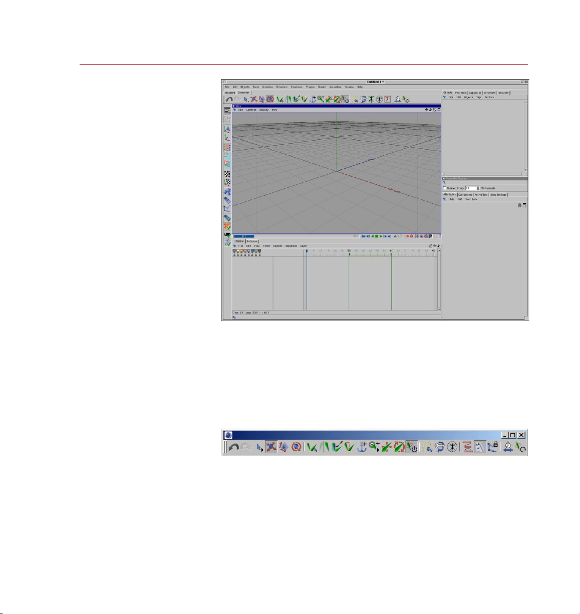
MOCC A LAYOUT AND PAL ETT E 5
Reach MOCCA commands quickly and save time using the predened MOCCA layout
and MOCCA palette. The MOCCA palette is integrated automatically into the MOCCA
layout. On this palette you’ll nd commands and tools from the Plugins > MOCCA
sub-menu as well as some of the most commonly used CINEMA 4D tools: move, scale,
rotate and the selection tools.
To use the predened MOCC A layout, choose Window > Layout > Mocca.l4d. You
can, if you wish, create your own layout for MOCCA. For details on how to do this,
please see the Conguration chapter of your CINEMA 4D Reference Manual.
the GUI .
If you want to open just the MOCCA palette rather than load the entire MOCCA
layout, choose Plugins > MOCC A > MOCCA Palette. The palette then appears as a
freestanding window, which you can integrate anywhere in the CINEMA 4D GUI. To
learn how to congure the GUI, please refer to the Conguration chapter of your
CINEMA 4D Reference Manual.
Page 14

Page 15

2 Introduction to IK
Page 16

Page 17
MOCC A
INTRODUC TION TO I K 9
Introduction to IK
MOCCA and Soft IK offer a
completely new approach for
animating characters. Almost all
possible movements are handled
via soft constraints. These enable
you to go beyond the world of
strict constraints.
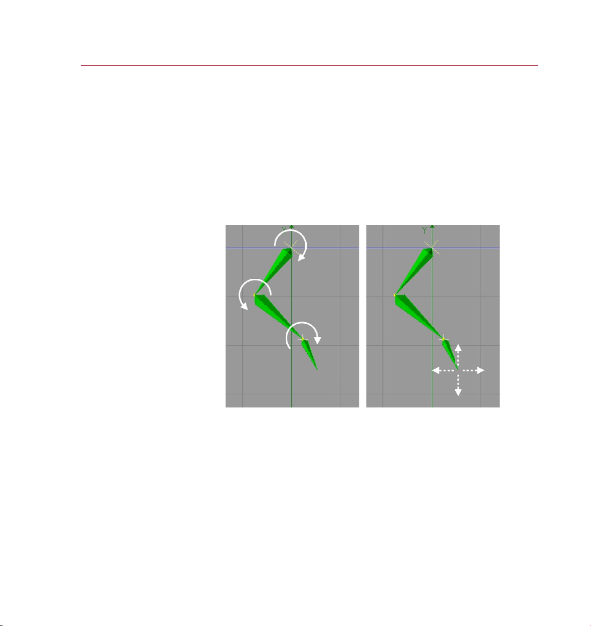
With Fo rward Kinematics ( left ),
each bo ne must b e rotat ed in
order t o move the a rm. With
Inverse Kine matic s (right), you
can move t he hand freely and
the other bone s in the arm will
move and r otate automatically
to ensure that th e bones remain
conne cted to o ne another.
Inverse Kine matic s helps you to
pose ch aracters qui ckly.
You have probably heard the term Inverse Kinematics (IK) before; it has become quite
a buzzword in the 3D world, particularly when it comes to character animation. The
main difference from the so-called For ward Kinematics (FK) is the direction in which
something is animated. Take an arm, for example.
Using FK, the arm would be animated from the shoulder downwards. This means that
you rst rotate the shoulder, then the upper arm, the lower arm, hand and nally the
ngers pointing to a specic location. The obvious disadvantage is the difculty of
trying to get the hand in a certain position in your 3D world, since any move of the
shoulder will require readjustments of all limbs that follow in the hierarchy. Having a
hand grab a cup of tea, lift it to the character’s mouth and place it back on the table
would involve a large number of rotations and adjustments, particularly because the
position and rotation of the cup and hand have to be synchronized at all times.
Inverse Kinematics offers an elegant solution to this problem. As the name suggests,
the direction of the animation is inverted. This means that moving the hand will force
the other joints between hand and shoulder to reposition in order to remain in contact
with the hand. A simple expression could lock the hand to the position of the cup,
allowing you to animate just one object, the cup, instead of two.
Inverse Kinematics has been a key part of the application since CINEMA 4D XL R5.
MOCCA IK offers a completely new approach. Almost all possible movements are
handled via constraints. Imagine a constraint as a force that always tries to nd an
equilibrium with other such constraints, just like an array of magnets that levitate a
metal sphere within their common magnetic elds.
Page 18

10 INTRO DUCT ION TO IK
MOCC A
The following example of earlier IK systems is familiar. You drag a bone target object
from one position to the next and the IK chain practically jumps into place. IK systems
that limit the freedom of rotation of each bone often create dead spaces. These,
sometimes large, spaces are created by overlapping rotation limits. The larger the
limits are for each bone, the bigger the dead zones. This can escalate to the point of
producing completely unmovable IK chains.
The new IK solution in MOCCA has been created with precisely this problem in mind.
By allowing the software to extend beyond these boundaries, it enables you to leave
behind the world of strict constraints.
How does this work?
The programming within Soft IK means that the more you stretch your constraints, the
more a dynamic counter-force will try to return the object to its initial rest position.
A basic example would be a comic character that grabs a heavy weight, which pulls
his arms and upper body to the oor. As soon as he lets go of the weights, the arms
will return to a more comfortable position, in other words, his rest position.
This animation is handled by what are called ‘tip effectors’ (control objects) that
attract the bones of a character. A lot of the work that needs to be done in character
animation involves a proper constraint setup, based on constraints for the angle
and position, which should facilitate animation later on. Just as in real life, these
constraints are soft. A constraint strength of 100% will not eliminate the other forces.
The object is still inuenced by all forces in the setup, making dead zones a thing of
the past. Careful placement and setup of these constraints will result in much more
elegant-looking animations that would otherwise be very difcult to achieve with
older IK solutions.
Some features in MOCCA might seem familiar, such as the Dynamics function in
Soft IK . However, MOCC A is not an addition to the CINEMA 4D Dynamics module
— it is an independent toolset in its own right. It has nothing to do with actual
dynamics, which are realistic simulations of physical events that give you enormous
control over all aspects of an environment. Naturally, those simulations also require
more processing power, the more realistic you want them to be. On the other hand,
MOCCA is a completely new technology, which emphasizes speed and reliability
above all else. Ultimately, it is the result that matters most.
Page 19
3 MOCCA IK Tag
Page 20

Page 21
MOCC A
MOCC A IK TAG 13
MOCCA IK Tag
MOCCA IK tags add a great deal
of control to your bone setup.
In these pages you’ll nd a
description of each setting in the
MOCCA IK tag.
The MOCCA IK tag helps make CINEMA 4D’s standard bones more powerful. Once
the tag has been assigned you can make full use of MOCCA for optimal control over
your bones.
You can assign the MOCCA IK tag by clicking on the object with the right mouse
button in the object manager. Not only has the MOCCA IK tag’s functionality been
improved but it also offers several new visual aides in the Object manager. Hence the
look of your IK tag will be different depending on if you activate the Anchor option
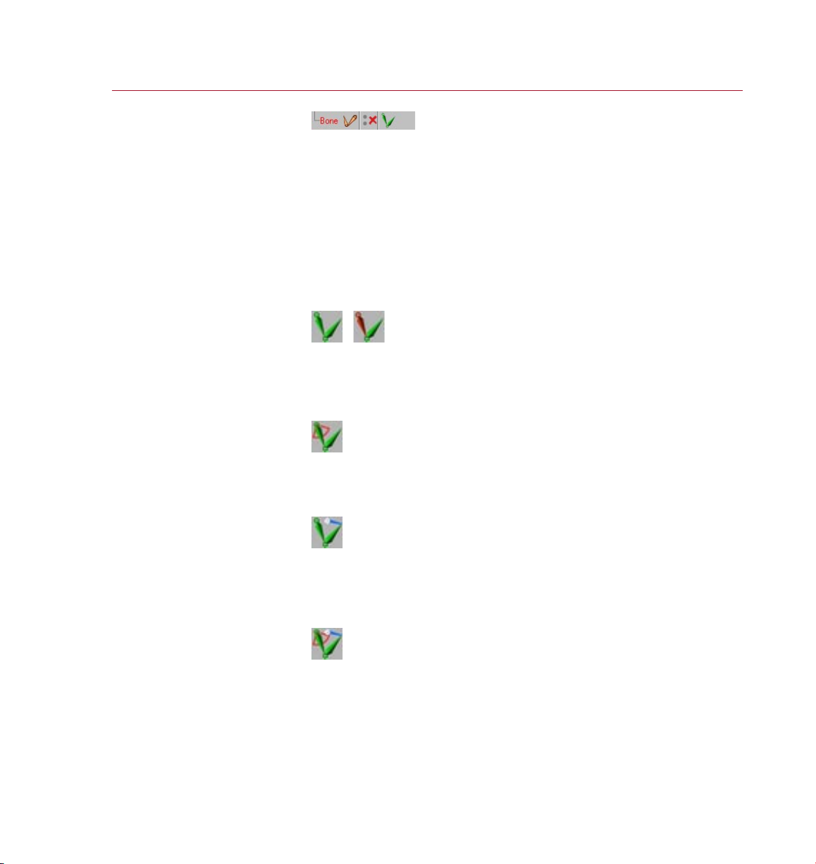
or if you add Limiters, for example. The MOCCA IK tag can look as follows:
Standard icon and with Anchor option
These are the standard icons after a MOCCA IK tag has been assigned (left) and
the icon after applying the Anchor option (right).
Once a Limiter has been applied
Once a Limiter has been applied to a bone the icon will look like this.
Once a Limiter has been adjusted
This icon will be used if the Limiter‘s values, within which the bones should move,
have been changed in the Attribute manager.
Limiters and altered values
And last but not least this is the icon that will be shown when Limiters as well as
altered values for Limiters in one MOCC A IK tag have been assigned.
Page 22
14 MOCCA I K TAG
MOCC A
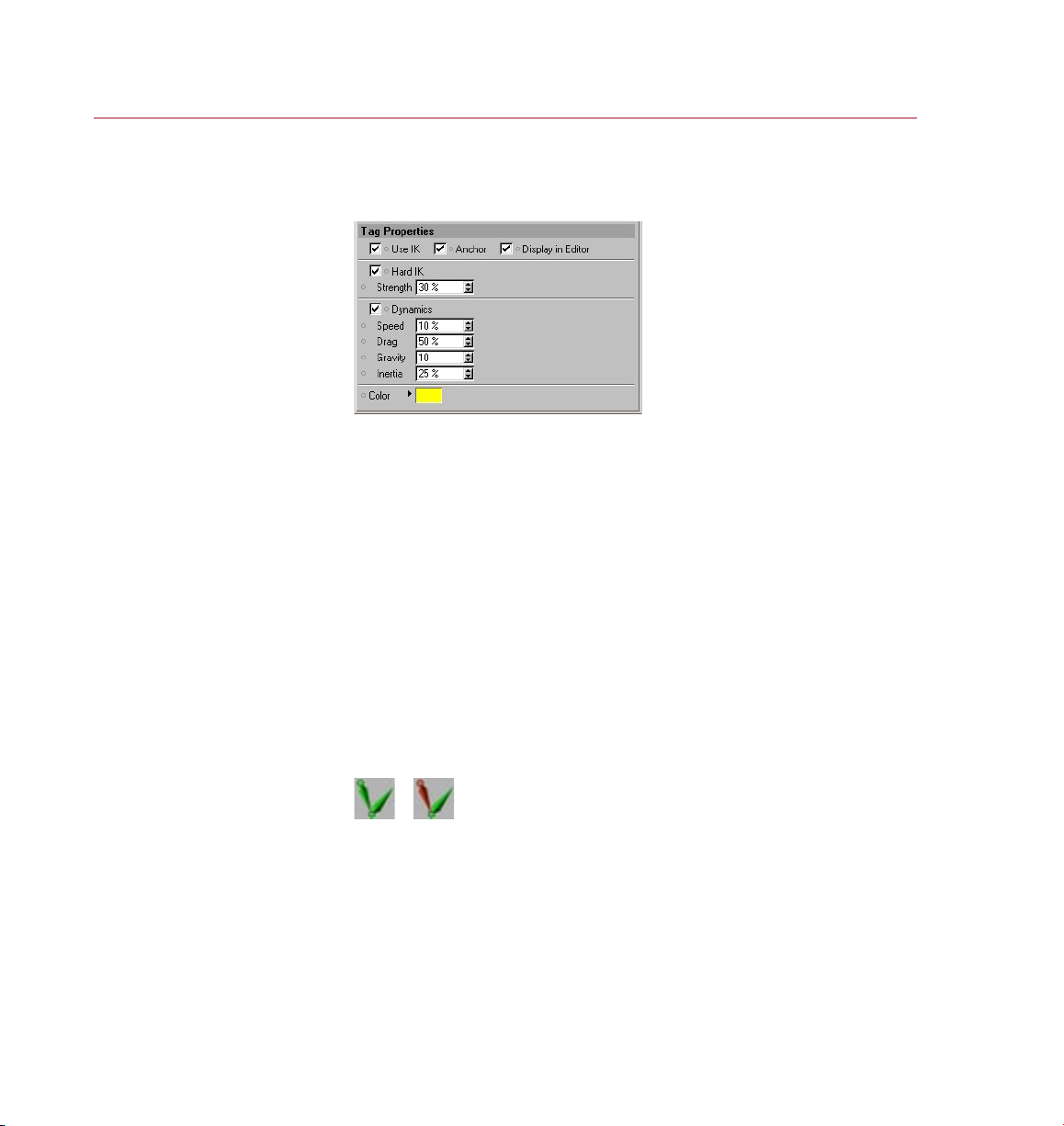
Attribute manager settings
Tag Properties
Use UK
This option activates or deactivates IK for the bone chain. The option can be found
within every MOCCA IK tag of the IK chain. Note that the entire chain is linked to this
command. Turning it off for one tag will deactivate it for the entire chain. The same
applies to turning it on again.
Anchor
An anchor is the root of any given chain. A classic anchor in a 3D character would
be the hips. Most of the time, this is the root element for the character bone setup.
Normally, you wouldn’t want the hips to jump out of place when dragging the goal
target of the left leg, thus twisting the entire character. Placing the root at a certain
point will tell the chain that the leg has to be held in place at its root, in this case
the hips.
The icon in the Object manager changes as soon as the Anchor option has been
enabled in the Object manager:
Anchor disab led (left) and
enabl ed (rig ht).
Page 23

MOCC A
MOCC A IK TAG 15
Hard IK
This option is only available when Anchor is enabled.
This option lets you control the bone’s movement and behavior. MOCCA uses Soft IK
from the previous version by default to control bones. As the name suggests, Soft IK
is ideal for use on “soft” bones because it exhibits a certain dynamic of its own. This
makes it prefect for cartoon characters or body parts that require a softer movement.
Hard IK, on the other hand, is less dynamic in its movement but is therefore faster
and does not exhibit its own dynamics.
Strength
This option is only available when Anchor is enabled.
This parameter modies the strength with which the skeleton will be held together.
It affects all movements and a high value results in precise, but harder animation.
You’ll quickly notice how, as the strength increases, the distances between each
bone in a stretched chain become smaller. High values will take additional time to
calculate though.
Dynamics
This option is only available when Anchor is enabled.
The dynamics parameters modif y the dynamic movements of the bone chain. The
dynamics settings affect an entire bone chain, whose root bone has this option
enabled. Since dynamics inuence the alignment of your chain, the effect becomes
more obvious if few constraints have been added. If you want to experiment with the
settings and get direct feedback, make sure you avoid setting constraints.
How do all these parameters interact?
There is no easy answer for this, since they affect each other. High Drag will cause
stiff joints, therefore limiting the effect of the other parameters. This makes drag an
ideal regulator for dynamics. On the other hand, Speed does not necessarily make
the movements of the chain faster. Test the different settings of the dynamics and
you’ll soon develop an intuitive understanding.
To switch dynamics on, enable the Dynamics option. You can then adjust the dynamics
of the bone chain using the following parameters.
Page 24
16 MOCCA I K TAG
MOCC A
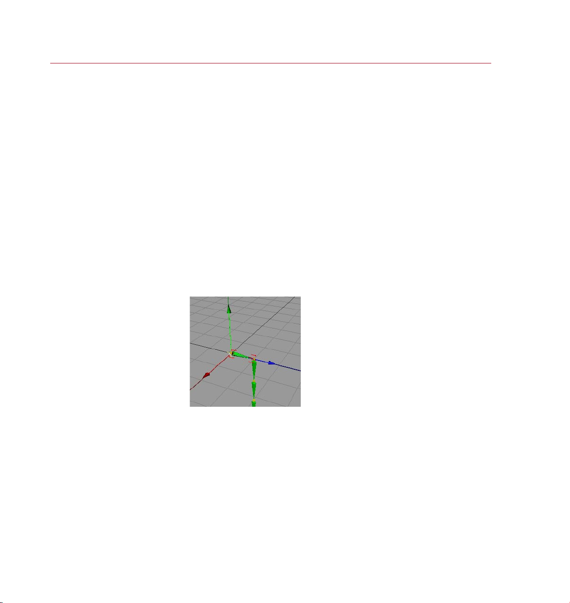
Gravit y pulls the bone s down,
in the dir ecti on of the world
syste m’s negat ive Y-axis.
Speed
This option is only available when Anchor is enabled.
Controls the speed at which the dynamic simulations are played back. The default
value of 10% initiates a slow reaction. Experiment with this setting. A small, light
character might move more quickly than a large, heavy one for example. The trunk
of an elephant would require slower movements and therefore lower values.
Drag
This option is only available when Anchor is enabled.
This parameter controls the resistance of the child bones toward the reaction to the
movements of the root bone. Imagine draining the lubricant from a joint mechanism
– the joint will become stiffer the more lubricant is removed. Similarly, the bones will
not move with the root as freely when using a higher percentage value. A word of
caution: Drag very much affects the other dynamic parameters and could seriously
dampen the whole dynamic movement.
Gravity
This option is only available when Anchor is enabled.
This parameter denes the strength of gravity that acts upon the bones. Higher values
result in a stronger bending of the chain on the Y-axis, downwards. Here again, small
characters might require lower values than large, heavy ones.
Page 25

MOCC A
MOCC A IK TAG 17
The lines conne cting the rst a nd
last bones are d isplay ed yell ow
in the viewpor t by defa ult.
Inertia
This option is only available when Anchor is enabled.
Inertia controls how much of a root bone’s movement is translated into torque for
its children. Torque is the force that causes rotation. Moving a bone chain around
will make torque affect the angle between each of the bones. Low values won’t
cause too much disruption in the chain, whereas high percentage values will jiggle
the chain more and more.
Color
This option is only available when Anchor is enabled.
Here you can set the color of the lines connecting the rst and last bones of your IK
chain as they are displayed in the viewport. The default color is yellow.
IK <-> FK
One of MOCCA’s most powerful new features is the ability to seamlessly switch
between IK and FK animation. Until recently you had to base the way you animated
your character on how it’s rigging had been set up. The respective situation will
dictate whether you move a leg by positioning the foot using IK or simply rotate the
shinbone using FK. The problem we would encounter, though, is that a rig that has
been set up using IK would lose its control object associations if a single bone in the
hierarchy would be selected and rotated independent of its IK control object.
Page 26
18 MOCCA I K TAG
MOCC A
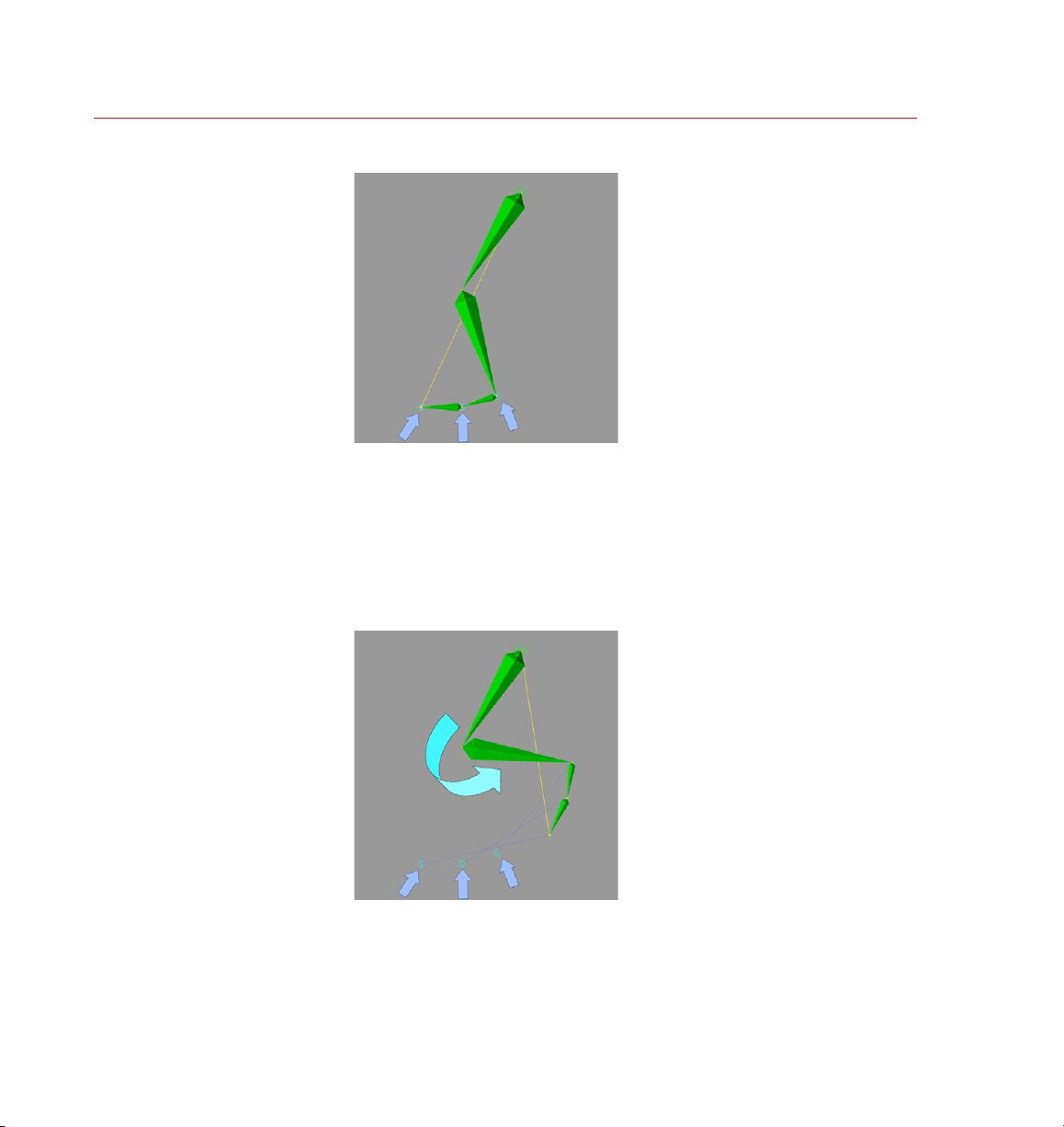
Three contro l objec ts ass igned to
a typical bon e setup for a foot .
Let’s take a look at an example of this in the following images.
The image shows a typical bone setup which will be controlled using IK. Three control
objects have been assigned for the foot (see blue arrows). Now the bone will be
bent to the rear.
In the past one could only bend the leg by moving the control objects using IK.
If you were to bend the leg by rotating the shin bone using the rotate function, the
control objects would retain their positions and it would be practically impossible to
animate the leg further using IK (see following image).
With the shin rotated, furth er
animat ion of the leg using IK is
almost imposs ible.
Page 27
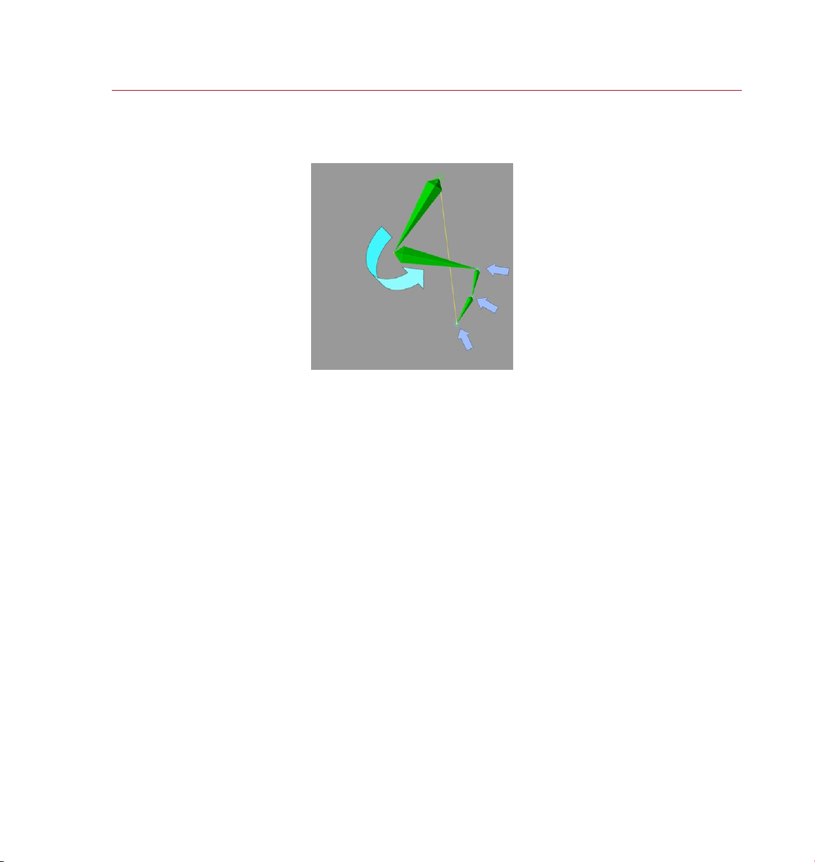
MOCC A
MOCC A IK TAG 19
MOCC A can now move the
control objects with your FK
rotat ions.
Now MOCCA lets you reach your goals any way you want. MOCCA will recognize
any control objects connected to your bones and move them with your FK rotation
(see image).
Display In Editor
You can use the Display In Editor option to control the display of visual aids in the
viewport. For example, this allows you to have the connection between the rst and
last element in an IK chain displayed as a thin line. If you don’t want these visual aids
to be displayed, disable the option.
Page 28
20 MOCC A IK TAG
MOCC A
The Constrain t settings allow
you to con trol th e bone chain
with other objects in the scene.
Constraint
This page is shown only if Anchor is disabled on the Tag Proper ties page.
The Constraint settings dene the controls that force the IK chain into another form
or direction; they allow another object to be used to move the bone chain.
Here’s a more precise explanation: the goal constraint uses the origin of virtually any
object in the scene to enable you to force the IK chain towards the position of that
object, assuming that the other potential constraints in your scene do not counteract
this. Since the IK chains follow the goal constraints, the bone angles will also be
modied. Therefore this is useful for setting up different poses, since all you have to
do is move about individual goal constraint objects.
If you want the chain to point at a constraint, you will have to work with a tip effector.
In other words, a null will be placed at the end of a chain and linked to a goal constraint.
This works similarly when you use the Set Up IK Chain command.
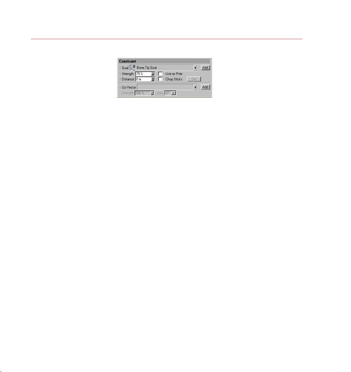
Goal
Drag an object from the Object manager into this box. This object will then serve as a
goal constraint. You can remove an object from this box by clicking the small triangle
next to it and choosing Clear from the drop-down list that appears.
Add buttons
These buttons allow you to add a root goal or up vector.
Strength
Imagine setting the ‘muscular’ force at which the constraint pulls on the bone. If you
have used several constraints with different strengths in your scene, the ones with
the higher values will be preferred by the chain.
Page 29
MOCC A
MOCC A IK TAG 21
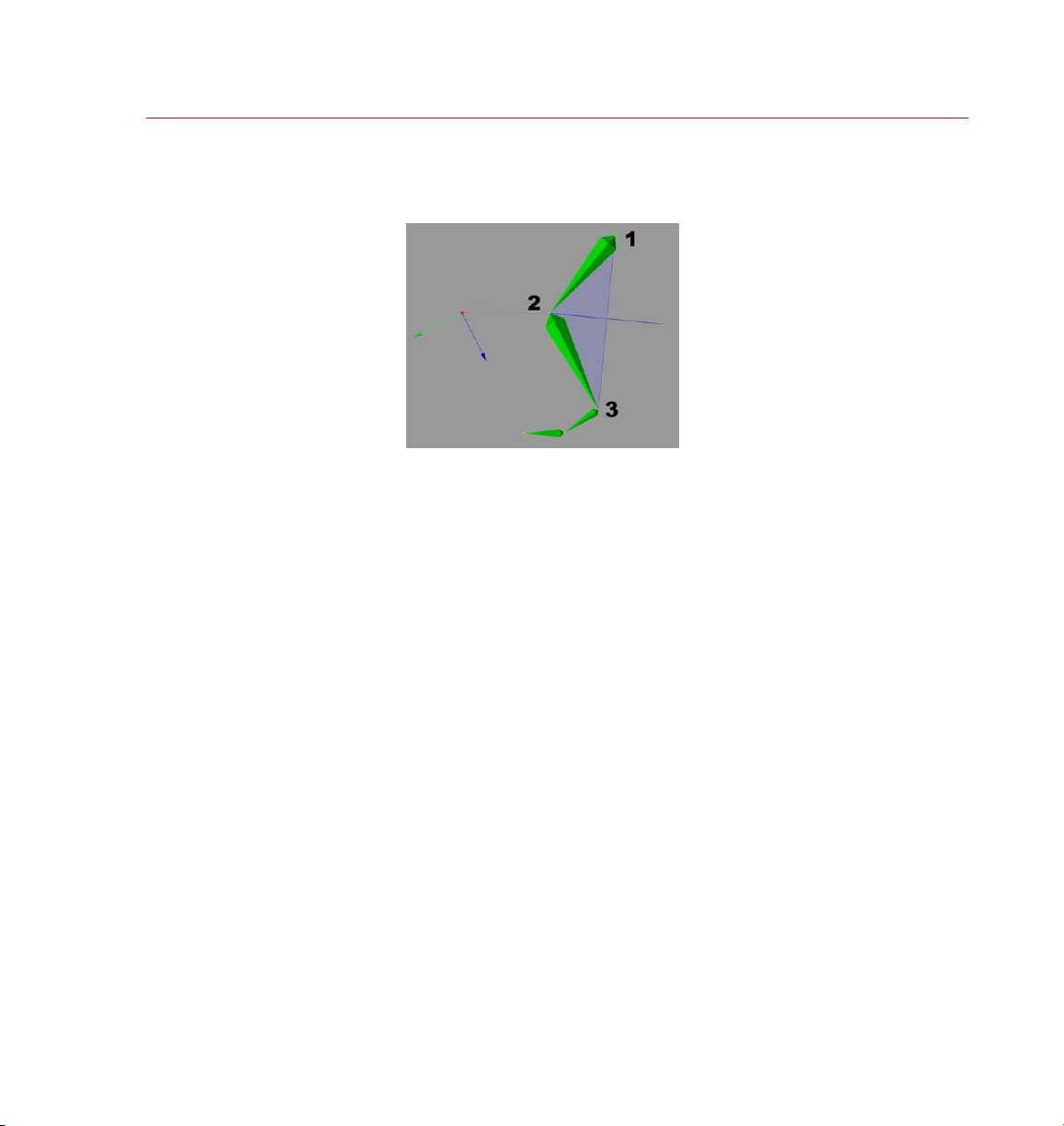
Pole vectors r epre sent th e planar
surfa ce bet ween these three
points.
Use As Pole
You can very easily obtain control over unwanted bone rotation using the option
Use As Pole.
Pole vectors represent a planar surface between the following three points (see
image) of a pair of bones:
1 The beginning of the rst bone.
2. The end of the rst and beginning of the second bone.
3. Around the end of the second bone.
The result is that the bones cannot be rotated independently of each other; the
rotation of the two bones is now controlled by the pole vector.
Use As Pole only has an effect when used with a root goal; the option has
no effect when used with a tip goal. This is down to the way that goals are
created — root goals are attached directly to the bone they should affect,
whereas tip goals are assigned an extra Null object.
Page 30
22 MOCC A IK TAG
MOCC A
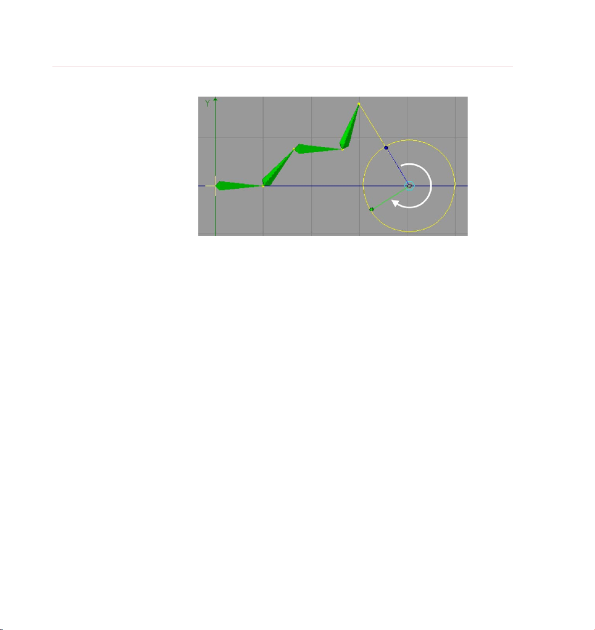
Chopsticks e nable you to rot ate
the chain around the value of
Distance
the Dis tance s etting.
The behavior of the Distance setting depends on the Chop Sticks setting. If Chop
Sticks is enabled, this parameter sets the length of the chopsticks (see below). If
Chop Sticks is disabled, it denes the distance between the tip effector and tip goal
constraint within the bone chain.
Chop Sticks
This setting, when enabled, allows you to move your character as if the joints were
connected to sticks, like shadow puppets. When using chopsticks you can pivot
around a point connected to an arm, just like the wheels of a locomotive train. Set
the length of the chopsticks using Distance (see above).
Set
This button is only available when the Use IK option (on the Tag Properties tab) is
disabled. When using chopsticks the Distance parameter allows you to change the
distance from the control object to the bone. To do this, switch off the MOCCA IK,
move the control object to the desired position, click Set and switch the MOCCA IK back
on. The new value for the distance will appear in the Distance box automatically.
Up Vector
Here you can drag and drop an object from the Object manager. That object will
then be used as an Up Vector object. Delete the Up Vector by clicking on the small
triangle next to it and selecting Clear.
Up Vector constraints let you orientate the axis of a bone towards a control object.
In this case, not the position, but the angle of the bone will be modied.
Page 31

MOCC A
MOCC A IK TAG 23
There are cases in which the chain may have various alternative ways of conforming
to all the constraints. Take a leg, consisting of an upper and lower thigh. The upper
thigh is parented to a root bone and the lower thigh has a tip effector, which is linked
to a goal constraint. If you move the goal constraint, the chain has no clear way of
knowing how the angles behave between root and effector. On longer chains this
can sometimes cause chaotic twisting of the IK chain. Obviously you’ll quickly notice
this when the character’s skin is xed to the bones, as it will twist with the chain.
The Up Vector gives you a chance to prevent this from happening by constraining
the orientation of the bone axis to the Up Vector constraint.
Strength
This value denes the strength at which the xed axis will be pulled towards the Up
Vector constraint. A value of 0% will completely ignore the constraint. A value of
100% practically nails the axis to the constraint. A value of 50% orientates the bone
with a bit of lag, just like a magnetic compass needle adjusting towards true North
after the compass has been moved.
Axis
Here you can choose between the various axes that point towards the Up Vector. The
options are Y, -Y and X, -X. If you choose -Y, the Y-axis will point in the exactly opposite
direction of the Up Vector, since an object axis arrow always points positively.
Page 32

24 MOCC A IK TAG
MOCC A
Limits dene t he position and
rotat ion spaces that y our chain
may not le ave. The o nly way fo r
the chain to break away fro m
constraints t hat try to pull th e
chain through the proh ibite d
space s. You could say that a lot
of stre ngth is n ecess ary to pull
the joints beyo nd thei r limits.
Rotation limi ts disp layed in t he
viewp ort (Show Limits enabled) .
Limit
these l imits is to use str ong
This page is shown only if Anchor is disabled on the Tag Proper ties page.
Show Limits
Enable this option to switch on the display of position and rotation limits in the
viewport.
Show Lim its dis abled .
Page 33

MOCC A
MOCC A IK TAG 25
Strength
This denes the strength of the position (X, Y, Z) or rotation (H, P, B) limits.
Be careful about using too high a Strength value, especially for a rotation limit. If
you’re using rotation limits on all bones, the limits might start working against each
other, causing the chain to twitch wildly. Therefore only increase the rotation limit
strength a little at a time.
Position limit settings (X, Y, Z)
Position limits enable you to offset bones in relation to their parent bone.
This can be useful where joints fork off, such as at the hips or the shoulders.
Remember to consider the equilibrium between the position limits and the
rest position of the bone structure.
Position limits give the bones boundaries that bind them with a given strength. The
Min and Max settings enable you to dene a point, area or space that is displayed as
yellow lines in and about the bone.
If you enable the X limits, say, and set a Min value of -50 and a Max value of +50, you
will notice a yellow line ex tending from both sides of the bone parent. If you want
to dene an area, you will have to use an additional axis (Y or Z). Using a third axis
will create a volume in the form of a box.
The box shape re presents three
position limi t axes.
All forces of the Soft IK limits are not static but behave dynamically. Imagine using a
rest position that is outside the space of your dened limits. In that case, the system
will try to nd a balance between both these forces, according to the strength values
used, and position the bones somewhere between both of them.
Page 34

26 MOCC A IK TAG
MOCC A
Using positio n limits, you can
heading rotation lim its and U p
construct th e chain w ith an
offs et bet ween the bones.
A bone ch ain, se t up with
Vector s.
Rotation limit settings (H, P, B)
This option enables you to conne the freedom of rotation of the joints in the chain.
The Min and Max entry elds next to R.H, R.P, R.B dene the rotation limits for
heading, pitch and bank. This is where you dene the angles within which the bones
can move freely. In the viewport, the limits are represented as pie sections, in red,
green and blue respectively.
Page 35

MOCC A
MOCC A IK TAG 27
The limits will only be active when they are enabled by checking the relevant boxes.
Otherwise the allowed movement or rotation will be unlimited.
If you want to prevent a change of heading, just enable the H limits. The default values
of 0 for Min and Max tell the bone to move 0 degrees on heading and it therefore
can only be pulled in that direction by increasing Strength.
Page 36

28 MOCC A IK TAG
MOCC A
Using th e parameters on this
page, you can control th e rest
position and rotatio n of each
joint to w hich th e character wi ll
retur n when th e const raints are
eithe r inactive or re duced.
Force Positio n enabled.
Altho ugh the tip effector h as not
been reache d, ther e are no gaps
Rest
This page is shown only if Anchor is disabled on the Tag Proper ties page.
These settings dene a rest position and rotation — a space to which the IK chain
will return when the other constraints are inactive.
Imagine a character that is pulled with great force from her original position. The
acceleration will cause her to stretch in the opposite direction of the pull. As soon
as the acceleration reduces, she will try to assume her initial pose (provided that no
other constraints prevent her from doing so). The Rest settings allow you to dene
this initial pose.
Force Position
If this option is enabled, the bones remain in contact, i.e. there will be no gaps
between the bones, even if the tip effector has not been reached.
between the b ones.
Force Positio n disab led. Th e
bones a re stretched apart as
they tr y to reach the tip effector.
Page 37

MOCC A
MOCC A IK TAG 29
Reset To Rest State
Clicking this button will cause the IK chain to return to its predened rest position
and rest rotation. Since you will probably have other active constraints in the scene
preventing this, the Use IK option will automatically be turned off at the root bone.
Strength, Pos X, Pos Y, Pos Z, Set
These values dene the initial rest position for the IK chain. You can set them by
moving the chain into the position you want and pressing Set or the Set Chain Rest
Position icon on the MOCCA palette.
The Strength setting regulates the strength at which the rest position will interact
with other forces. The higher the value, the greater the inuence of the rest position
on the character.
Strength, Rot H, Rot P, Rot B, Set
These settings dene the initial rest rotation of the IK chain when no other constraints
are active. You can set them by arranging the chain as you want and pressing Set or
the Set Chain Rest Rotation icon on the MOCCA palette.
If you have set a rest position for the arm, which also has a tip effector connected to
it, the chain will try to nd a common denominator for both forces. If you try to pull
the arm away from its rest position with a goal constraint, you will have to use more
force than if you hadn’t used rest rotation. Eliminating the goal constraint will cause
the chain to return to its rest rotation immediately. This form of constraint should be
preferred to the classical rotation limit, since it allows for more natural movements
with less strict prohibited spaces to which the chain can move.
The Strength setting controls the strength at which the rest rotation interacts with
other forces. The higher the value, the greater the inuence of the rest rotation on
the character.
Page 38

30 MOCC A IK TAG
MOCC A
MOCCA IK Commands
These commands help you to
create MOCCA IK chains and
fully automate your setup.
When setting up a Soft IK chain, you’ll need to use the MOCCA IK commands. Using
these, you can add anchors, goals and more and save time with the Setup IK Chain
tool, which fully automates the Soft IK setup for simple bone chains. You’ll nd these
commands on the Plugins > MOCCA sub-menu as well as on the MOCCA palette.
Setup IK Chain
With a bone chain selected, choosing this icon from the MOCCA palette, or from the
MOCCA Plugin menu, will add a MOCCA IK tag to the root bone, with the Anchor
option enabled. The child bones will also receive a MOCC A IK tag, and a tip effector
will be added to the last bone. The effector is linked to a goal constraint parented to
the root bone of the chain. This will set up your IK chain at the press of a button.
Add Anchor
This command adds an anchor to the selected bone.
Add Root Goal
The root of an individual bone is also where its object axis is placed. This command
puts an effector at the bone’s origin. The effector is linked to a goal constraint, which
is parented to the chain’s root bone. It will automatically receive the sufx ‘Root Goal’.
Moving this goal object will give you direct control over the position of the joint.
Add Tip Goal
This command puts an effector at the tip of the bone. The effector is linked to a goal
constraint, which is parented to the chain’s root bone. It will automatically receive
the sufx ‘Tip Goal’. Moving this object gives you inuence over the direction of the
Z-axis for the respective bone.
Page 39

MOCC A
MOCC A IK TAG 31
Add Up Vector
By selecting this, an Up Vector will be added to the selected bone, constraining its
Y-axis orientation towards a control object placed above it. This object will adopt the
name of the bone along with the sufx ‘Up’. Adding this to the bone called ‘Upper
thigh’ for example, would result in an Up Vector control object with the name ‘Upper
thigh.Up’. If you want to constrain the X-axis of the bone, select its MOCCA IK tag
and, on the Attribute manager’s Constraint page, choose a different axis from the
Axis drop-down list.
Set Chain Rest Position
This command sets the local positions (i.e. the position relative to the immediate
parent object) of all objects in the IK chain as the rest position in the MOCCA IK tag.
The command gives you an easy way to dene rest poses. See also the description
of the Rest tab earlier in this chapter.
Set Chain Rest Rotation
This command sets the rest rotation of all bones in the IK chain that have MOCCA IK
tags. See also the description of the Rest tab earlier in this chapter.
Auto Redraw
You’ve probably noticed that a great way to test the movements of your IK chain,
especially in combination with the Dynamics function of Soft IK, is to press the Play
button (or hotkey: F8).
However, since the Soft IK chain works with soft constraints, the animation reacts to
a number of different factors. This means that the animation might not be nished
at the last frame. The joints might still come to rest slowly. To display those changes
without playing back the entire animation, you can use the Auto Redraw command
in MOCCA. Once enabled, it will constantly update the calculations, displaying the
reactions of your IK chain immediately.
When choosing this command, the dialog will enable you to set the redraw step in
milliseconds. If you have activated the MOCCA layout by choosing Window > Layout
> Mocca.l4d, you will nd the dialog already below the Object manager. Normally,
the animation will be played back in realtime; for PAL systems, that means 25 frames
per second, for NTSC it is 30. Each frame will therefore be displayed for 1/25 or 1/30
of a second before it is updated again.
Page 40

32 MOCC A IK TAG
MOCC A
The default value of 50 milliseconds (20 frames per second) is quite enough to make
the movements smooth. Note that each redraw costs processing power. Higher redraw
times will cost more processor time. 50 milliseconds is a good average value. Very
complex scenes may, however, require faster redraw times.
Auto IK-Lock
The Auto IK-Lock option is closely related to the ability in MOCCA to seamlessly
switch between IK and FK when you are animating. If the option is enabled, when
you animate the tag’s bone with FK, all of the bone’s control objects such as goals
and up vectors will move along with the bone automatically. If the option is disabled,
MOCCA will still rotate the bone but it will ignore the control objects.
Page 41

4 Bone Tool
Page 42

Page 43

MOCC A
BONE TO OL 35
Bone Tool
With the bone tool, you can
create and adjust bone chains
quickly and easily, using a
variety of tools.
Bones i n the Obj ect manager
befor e sele cting t he bone tool
(lef t) and af ter (right).
The bone tool is the tool of choice for preparing your virtual characters
for that big Hollywood role. MOCCA was given an extra tool to let you
put together your 3D star’s skeleton quickly and intuitively and easily
position them in your scene. If you make a change to a bone, changes to
its dependent bones will be made accordingly. It has never been easier to edit bones
in CINEMA 4D.
Selecting and deselecting the bone tool
You’re probably wondering why we have a special section just for selecting a tool,
even though its so obvious. Well, this section is less about actually selecting the tool
and more about the effect that selecting this tool has, i.e. what happens to the bones
when you select this tool or switch from it to another tool.
Selecting the bone tool is like beginning a phase – the bone editing phase. All bones
in the scene are deactivated when the bone tool is selected. The red check marks in
the object manager will turn from green to red.
In addition, the bones will be reset to their initial rest position and will lose their
deformation effect on the mesh.
This effect is similar to the Reset Bones command in the Object manager.
A further effect of selecting the bone tool is that the Use Animation and Use
Expressions options on the left toolbar will be disabled. This will prevent the bones
from being affected by animation keys or expressions.
When yo u select the bo ne
tool, the Use Animation and
Use Expressions options in the
left toolbar will be di sable d
automa tically (lef t). They will
becom e active again (right)
as soon as you change to a
different tool.
Page 44

36 BONE TO OL
MOCC A
The various tools are availabl e
from the Attribute man ager.
As soon as you switch from the bone tool to another tool such as rotate, the bones
will be reactivated automatically and the mesh will be inuenced by the bones once
again. The Use Animation and Use Expressions options will also be activated again.
If, before using the bone tool, you’ve edited the bones or recorded keys for them
and so on, then when you switch from the bone tool to another tool the bones will
jump back to the positions and rotations they had at the time when you selected the
bone tool. In other words, you’ll lose any position and rotation changes that you’ve
applied to the bones while the bone tool was selected.
Although selecting the bone tool can be compared to the Reset Bones command,
deselecting the bone tool is not, in turn, similar to the Fix Bones command.
The difference is that Fix Bones xes the bones to their present position and rotation
and denes this as the new initial state, whereas deselecting the bone tool does not
x the bones — it simply activates their deformation proper ties.
Therefore we recommend that you edit the bones using the bone tool before applying
expressions and so on. If you must make changes to the bones later using the bone
tool, before you deselect the bone tool, choose the Fix Bones command to x the
bones in their new position and rotation.
Attribute manager settings
Add Bone
This command adds a bone to the scene. The bone has a default length of 100 m
and points in the direction of the Z-axis. Pressing the button twice, however, does
not add a child bone to the previous bone but another independent bone, with the
same parameters as the rst one. If you want to add a child bone, use the Add Child
Bone button instead.
Add Child Bone
Clicking this button will simply add a child bone to the chain; this is placed at the
tip of the previously created bone or child bone. It adopts the parameters of the
preceding bone, as well as its name.
Page 45

MOCC A
BONE TO OL 37
Continuously using this command will add a new child bone for every push of the
button, quickly creating an entire chain.
You can also add child bones by Ctrl-clicking in the viewport, in which case a new
bone is added to the chain between the tip of the last bone and the position of the
mouse pointer. If you look closely, you’ll notice a yellow dot at the origin of each
bone. These are handles. Drag them to scale and rotate the bones interactively in
the viewport.
Split Bone
This will split the bone in half. Together, the newly created bones will have the same
length as the original. The overall length of the chain therefore remains unchanged.
You can also split bones interactively in the viewpor t. While pressing the Shift key
simply click on the bone at the point at which you want to split it.
Use this command before setting up Soft IK , since the Setup IK Chain command will
also set the rest position of the bones. If you then split the bone, a new bone with
half the length of the original will be placed at the previous origin. The other new
bone will also be shorter but cannot reach the tip of the preceding bone, since the
old rest position has also been copied. This would lead to gaps in the IK chain.
Add/Update Null Bone
A Null bone is a bone without inuence on the geometry of the object to which it
is assigned. In other words, it is a bone with a strength of 0% and a length of 0 m
— literally null.
The Att ribute manager settings
for a Null bone.
Bones, just like any other object in a hierarchy, always work with the information of
their parent object, such as its limits or positions. Null bones offer the benet of not
affecting the geometr y and can therefore serve as a master system.
So why not use a normal Null object instead? The answer is simple: a bone chain
does not allow other objects (such as the normal Null objec t) to penetrate its
hierarchy. Other wise, the bones might no longer be xed and results would be quite
unexpected.
The Add/Update Null Bone command adopts the rotation and position of and is
placed at the origin of the selected bone. The rotation of the selected bone is cleared.
The great advantage is that you can easily set rotation limits for non-rotated bones
without having to do the math for each of them.
Page 46

38 BONE TOOL
MOCC A
Use this command before Setup IK Chain, since the latter will x the rest position of
the bones. If the Null bone is added later on, the following bone cannot be placed
at the tip of the shorter null bone, because it inherits the rest position. The chain
would be elongated.
Page 47

5 Bone Mirror Tool
Page 48

Page 49

MOCC A
BONE MIRROR TOOL 41
Bone Mirror
With this tool you can mirror
individual bones and entire
chains including tags, Claude
Bonet maps and much more.
Befor e using t he bone m irror
tool (left) and afte r (righ t).
The bone mirror tool is a powerful accessory that can speed up your work
with bones by mirroring not only the bones but also tags, constraints,
selections and more. To select the bone mirror tool, choose Plugins >
MOCCA > Bone Mirror or select the Bone Mirror icon from the MOCCA
palette. In both cases, this opens the Bone Mirror dialog, from where you can set up
the operation of the tool, before clicking the Mirror button to make the changes.
The bone mirror tool mirrors only the bones and the Null objects within the
setup (such as nulls for root goals), NOT geometry (meaning 3D volumes). If
you want to mirror geometry, use the Mirror tool from the Structure menu.
Since the Bone Mirror tool was developed primarily for use with Soft IK
it does not support other functions such as IK expressions or XPresso
expressions.
Page 50

42 BONE M IRROR TOOL
MOCC A
Attribute manager settings
Plane
This is where you select the plane onto which the setup is mirrored. Imagine putting
half an orange onto a mirror, open side facing the mirror. The half orange suddenly
appears like a complete one. The mirror is the equivalent of the tool’s plane that you
choose from this drop-down list.
Origin
The Origin setting denes a point through which the Plane should pass, thus dening
the mirror’s position. Choose one of the following settings.
Selected
This will mirror the selected bone with the mirror plane passing through its object
axis. The rotation of the axis will be ignored, since the bone mirror tool always
mirrors parallel to the plane that you have chosen.
Parent
The setup will be mirrored according to the position of the axis of the selected
bone’s parent. Again, the rotation of the axis will be ignored, since the bone mirror
tool always mirrors parallel to the plane that you have chosen.
Top Most
In this case, the root bone sets the origin of the mirror. Here too, only the mirror
plane is of importance.
World
If you choose the World setting, the origin of the world coordinates will be used,
regardless of the rotation of origin.
Page 51

MOCC A
BONE MIRROR TOOL 43
Auto Find Center, Match Search
The Auto Find Center option is designed to help you mirror Claude Bonet maps, point
and polygon selections, as well as vertex maps. Imagine having built a character and
set up half of it with bones. You might also have set the range of inuence of some
of the bones with the Claude Bonet tool. Naturally, you’ll want the bone mirror tool
to copy those weights properly to the other side, too.
If you disable the Auto Find Center option, the object axis of the bone setup will be
used instead. The object axis isn’t necessarily at the center of your character’s points,
though. Enabling the option will nd the center of the points, which can create very
accurate results in symmetrical models.
The Match Search box is where you set an amount of tolerance with which the bone
mirror tool will compensate for irregularities within the model. If the bone mirror tool
does not nd exactly the same corresponding points on the other side of the setup, it
will search for them within the radius that you can set. You should experiment with
this setting. Very small values tend to produce unconvincing results.
Sufx
Here you can set a name sufx that is added to the mirrored elements. This serves for
organizational purposes, avoiding confusion between the various resulting bones.
If you are mirroring the left half of the character, you might set the sufx to ‘_R’. An
upper thigh named ‘ThighUp’ would, after mirroring, create a bone with the name
‘[ThighUp_R]’ on the right side.
Prex
This is where you can set a prex to be added in front of the mirrored bones. Taking
the previous example (see ‘Sufx’, above), setting the prex to ‘R_’ will cause the
right side of the upper thigh to be named ‘R_ThighUp’ after mirroring.
Replace ... With
These settings enable you to rename a bone while mirroring. For example, if you have
already named a left upper thigh ‘[ThighUp_L]’, it would make little sense to leave
‘_L’ in the name of the right side. Simply type _L into the Replace box and _R into the
With box. The mirrored bone will automatically be named ‘[ThighUp_R]’.
Clone Tags
You can also mirror all the tags assigned to a bone element by enabling this option.
Note that the Mirror Constraints and Mirror Inuences options are available only
when Clone Tags is enabled.
Page 52

44 BON E MIRROR TOOL
MOCC A
Clone Animation
If this option is enabled, the chain’s existing animation tracks are cloned.
Mirror Children
When enabled, this option will mirror the children of the selected bone, as well as any
control objects. If the option is disabled, only the selected bone will be mirrored.
Mirror Constraints
If this option is enabled, existing Restriction tags and the constraints dened in the
Attribute manager will be mirrored as well.
These restrictions are used to control which part of the body the bone may deform.
Even combined vertex maps with parented polygon models can be mirrored,
despite the fact that the vertex map is not assigned to the bone, but to the Polygon
object above it. The only necessary condition is that the Mirror Inuences option is
enabled.
Mirror Inuences
When enabled, this option will mirror all inuences a bone may have on a model.
These inuences can refer to Restriction tags assigned to point or polygon selections
as well as to vertex maps. This option is especially useful when mirroring Claude
Bonet weighting.
Mirror
Click this button to apply the Mirror tool to the selected bones.
Page 53

6 Claude Bonet Tool
Page 54

Page 55

MOCC A
CLAUDE BON ET TOOL 47
Claude Bonet Tool
The process of weighting bones is
quick and easy with this tool.
It enables you to set inuences
and assign them to bones at the
same time.
The Claude Bonet tool takes its name from the word ‘bone’ and from the
name of the leading exponent of impressionism, Claude Monet. Before
we explain what the Claude Bonet tool does, some explanation of bone
weighting is in order. Bones are deformers. In other words, bones are
objects that have no geometry themselves but are used to deform volumes (e.g.
the esh around them). Usually, a single bone won’t be enough to set up a realistic
skeleton. Instead you’ll probably use several complete chains, where each bone has
a function.
To use the bones efciently within the chain, you’ll have to assign separate parts
of the geometry to each bone, to avoid having the foot bones curl the ears of the
character, for example. This process is called ‘weighting’.
In earlier versions of CINEMA 4D, this weighting was achieved using traditional vertex
map weighting tools. Back then, you assigned weighting to points and linked them
to the bones via Restriction tags. You can still do this, but there is an easier way.
Claude Bonet makes this process far simpler by enabling you to set inuences and
assign them to bones simultaneously and, as its name suggests, you paint these
weightings onto the bone.
To select the Claude Bonet tool, choose Plugins > MOCCA > Claude Bonet or click
the Claude Bonet icon on the MOCCA palette.
The settings for the tool will then appear in the Attribute manager.
Once you have adjusted the settings as described below, just select a bone and ‘paint’
the weighting onto the bone in the viewport, using the mouse.
Page 56

48 CL AUDE BO NET TOOL
MOCC A
In the At tribute manag er,
you’ll nd all the comman ds
and options tha t are needed to
Attribute manager settings
weight the bone s.
Only Modify Visible Elements
If this option is enabled, you can paint visible elements only. Invisible elements are
ignored.
Display All Bones
When enabled, this option will display the inuences of all bones on the geometry,
in the selected chain. What you’ll see is the color display of the existing Claude Bonet
weighting range. When adjusting the weighting of a single bone, we recommend
disabling this option. Inuences might overlap near their borders, making it difcult
to judge a single bone’s weighting.
Left : the le ft leg has bee n
weighted usin g the Claude
Bonet t ool wit h Displ ay All
Bones e nable d.
Right : Display All Bones
disabled.
Page 57

MOCC A
CLAUDE BON ET TOOL 49
Force Shading e nable d (top) and
disabled (bo ttom).
Paint Absolute
The links between the bones and the individual points in the mesh will be saved by
Claude Bonet as weighting information within the points themselves. Normally, if
you paint weighting with a strength of 20%, for example, each brush stroke will
add another 20% to the area. By holding down the Ctrl key while you paint, you can
erase the weights.
Paint Absolute will disable the above behavior. You’ll then paint with the absolute
Strength value only.
Force Shading
Normally, if you paint the weighting in, say, the Lines display mode, it can be difcult
to weight the bones by eye. At best the only weighting information you’ll see in
the viewport will be colored lines and points. To make your work easier, enable this
option. Quick Shading will then be used.
Page 58

50 CLAUDE BONET TOO L
MOCC A
With this comma nd, you can
apply the same Claude Bonet
weight to multiple bones. This
helps you to quic kly set the
weighting for s imilar bones such
as the nger bon es of a hand.
Set Reference
It’s not absolutely necessar y to assign all joints of a bone chain a separate weighting
for the mesh. Particularly in areas where a lot of bones control a small section, such
as hands, it may be easier to simply apply the same Claude Bonet weights to all
ngers. In this case, you can set a reference weight for the rst nger and reuse it
for the following ngers.
This is precisely what Set Reference is implemented for. Select a bone and click this
button. If you haven’t set any weights yet, the button will have no effect. Otherwise,
a list will pop up; choose the bone whose weighting information you want to apply
to the selected bone and click OK.
Strength
This is where you set the strength with which you paint. A value of 50%, for example,
would allow the bone to have limited inuence on the mesh. The strength is added
relatively; if you paint weighting with a strength of 20%, for example, each brush
stroke will add another 20% to the area. Enabling the Paint Absolute option turns off
this relative mode and allows you to paint with an absolute Strength value.
By holding down the Ctrl key while you paint, you can erase the weighting.
Set Value
This button sets the current weighting strength for the selected bone across the entire
area of the assigned geometry. If you select a character’s hip bone, for example,
dene a strength of 100% and click Set Value, the bone would have full inuence
over the entire geometry of the volume. This is a quick way of painting the weights
across the whole chain.
Page 59

MOCC A
CLAUDE BON ET TOOL 51
Befor e using S et Value ( left ) and
after (right ) with Str ength s et
to 100% .
Radius
The Radius denes the size of the brush with which you paint the weights. Experiment
with the radius.
Remove Paint (This Bone)
Erases the weighting of the selected bone. You can use this function if the weighting
is bad and you want to start again instead of reworking the bad map.
Remove Paint (Hierarchy)
Removes the weighting of the selected bone hierarchy, from the active bone down
to the last bone of the chain. If you have to completely rebuild and re-weight a
character’s arm, for example, it can make sense to keep the bones and just completely
reapply the weighting.
Remove Paint (Scene)
Removes all weighting for the entire scene. This can be useful if you discover you have
painted the character incorrectly and would rather paint it again from the beginning,
or if you want to edit the character entirely including new setups.
Page 60

52 CLAUDE BON ET TOOL
MOCC A
Further usage advice
When weighting bones with Claude Bonet it is important to know which of the three
possible bone parameters you are working with:
1. Smart Bone disabled.
2. Smart Bone enabled, Absolute Vertex Map disabled.
3. Smart Bone enabled, Absolute Vertex Map enabled.
Each of these properties requires a different method of application of the Claude
Bonet tool because each property uses a different algorithm to deform the mesh
with the bones.
1. Smart Bones disabled
When using bones in the classic CINEMA 4D style (the Smar t Bone option was rst
added in version 8.5) it is important to know that ever y bone will inuence EVERY
point of an object even WITHOUT application of the Claude Bonet tool. Therefore
if you forget to paint a bone with Claude Bonet and you have not assigned a vertex
map to the bone, the bone will affect the entire mesh and this can lead to unwanted
deformations. How much the bone affects the mesh will depend on the size of the
bone and how far away it is from the points.
2. Smart Bone enabled, Absolute Vertex Map disabled
Generally speaking, the same applies here as with the previously described function:
if no maps have been applied, the bones will inuence all points of an object,
THE DIFFERENCE BEING that a different algorithm is used. This algorithm affects
substantially fewer points located a greater distance from the bone. In principle,
the Smart Bone option can be added at any time to bones already weighted with
Claude Bonet.
3. Smart Bone enabled, Absolute Vertex Map enabled
As mentioned in the CINEMA 4D reference manual, if Absolute Vertex Map is enabled,
the maps alone will control the entire weighting of the bones. This has the advantage
that any points that are not referenced in the map (i.e. points not painted with Claude
Bonet) will NOT be deformed by the bones — each and every point must be accounted
for in the maps. In addition, none of the other parameters such as function or strength
can be used for bones within the hierarchy.
Page 61

MOCC A
CLAUDE BON ET TOOL 53
Left : Her e is an exa mple of a
defor mation of a simpl e mesh
without Claud e Bonet and
without Smar t Bone enable d
(Func tion se t to 1/r^2).
Right : Here i s an exam ple of a
defor mation of a simpl e mesh
without Claud e Bonet and with
Smart Bones e nable d (Function
set to 1/r^2) but with Absolute
Verte x Map disabled. You
can see how the Smart Bone
algor ithm deforms the object in
a quite di ffer ent man ner to th e
classic algorithm (w ithout the
Smart Bone functio n).
Here is an example of a
defor mation of a simpl e mesh
without Claud e Bonet but with
Smart Bone AND Abso lute
Verte x Map both enabled.
No defo rmation can be seen
because no map s have bee n
applied to the bones.
Examples
The difference between using smart bones and normal bones becomes clear when
you take a look at the following examples. For these examples no Claude Bonet maps
were used in order to make the differences as clear as possible.
As these examples suggest, you may need a different Claude Bonet weighting when
using smart bones than you do when using normal bones.
Page 62

54 CL AUDE BO NET TOOL
The def ormation of a cub oid
with few subdiv ision s in a
HyperNURBS object via fo ur
bone objects (the pol ygonal
cube was s ubdiv ided th ree tim es
using the Knif e Tool). Ea ch bone
was weig hted us ing Clau de
Bonet , wher e the wei ghting
overla ps the se gment s (righ t).
The def ormation of a cub oid
with a few more subdivisions
(espe ciall y at the joints) within
a HyperNURBS object via fo ur
bones . Each bo ne was weighted
using Claude Bo net, w here the
weighting overlaps th e segme nts
(right). Because th e objec t
contains more subdiv ision s at
the joints, the outer fo rm will
retain its original f orm mor e
close ly than w ill an object with
This does, tho ugh, re quire
more work when p aintin g the
weighting onto the mesh.
MOCC A
Additional comments
The structure of the object is also very important with regard to painting maps. A
highly subdivided object will be deformed differently than an object with fewer
subdivisions.
fewer subdivisions .
Page 63

7 Cappuccino Tool
Page 64

Page 65

MOCC A
CAP PUCCINO TOOL 57
Cappuccino Tool
Cappuccino is MOCCA’s
integrated motion capture tool.
It enables you to create lifelike
motion for your characters,
from a head nodding in
agreement to a gecko catching
a y with its tongue.
Capture your mo use movement s
using th e options and commands
in this di alog, w hich op ens whe n
you choose the Cappuccino
command.
With Cappuccino you can quickly create all kinds of realistic movements for
your 3D characters and models, simply by recording mouse movements.
Cappuccino is MOCCA’s integrated motion capture tool. Take an object,
activate the function and drag it around the viewport. All movements of your mouse
will be captured and recorded frame by frame in the object’s animation track.
Cappuccino is good for setting so-called secondary motions such as the movement of
pigtails which you really don’t want to animate manually. Furthermore, you can more
easily animate vehicles using the top view or move planes or birds across the sky.
Cappuccino produces a large amount of unnecessary keys since it sets a key at every
frame of the animation. It is generally a good idea to apply the Key Reducer after
using Cappuccino.
To select the Cappuccino tool, choose Plugins > MOCCA > Cappuccino or click the
Cappuccino icon, shown above, which you’ll nd on the MOCCA palette.
The Cappuccino dialog opens.
Cappuccino dialog settings
Page 66

58 CAPPUCCINO TOOL
MOCC A
Action pane
Here you’ll nd the buttons for recording the keyframes in different ways.
Single Keyframe
This will record keys for the selected object(s) at the current Timeline position and
according to the Where and What selections within the dialog. Simply select an object,
or objects, and click Single Keyframe.
This button describes the same functionality as the record button on the Timeline.
Having the function available directly in the Cappuccino dialog is more convenient in
case the Timeline is not visible for whatever reason. It is by all means conceivable that
one could mix automatic keyframes and manually set key frames using Cappuccino.
Start Realtime
This button prepares MOCC A for multiple-keyframe recording. It tells MOCCA to
start recording as soon as the mouse button is pressed within the viewport and stop
when it is released again.
Look at the Timeline: when you rst press the mouse button in the viewport, the
Timeline pointer will start running and then stop abruptly when you release the button.
MOCCA will record a key for each frame of the animation. By default, in PAL mode,
this will result in 25 keys per second; in NTSC mode, 30 frames per second. Use the
KeyReducer tool to reduce the number of keyframes if necessary.
Here, ‘second’ does not represent a real-time second, i.e. the actual
time the object takes to move. This is also dependent upon the speed of
your processor and the scene’s complexity. A simple cube in an empty
environment will behave differently to a complex model of a car in a city
landscape!
It’s important to keep these factors in mind and to deactivate objects that
aren’t needed for the recording in order to free up some of your computer’s
performance if necessary. Another possibility is to work with proxy objects;
for example, in the case of animating a car, you could animate a cube in place
of the car and then transfer the animation from the cube to the car.
Page 67

MOCC A
CAP PUCCINO TOOL 59
The Stop button during the
recor ding (l eft) a nd after (right).
Stop Realtime
Think of this as that ‘Quiet: Live Recording’ sign that you see in recording studios. Its
sole purpose is to indicate when the recording has nished. When you’re not recording,
this button is appears ‘pressed’. During recording, it appears ‘unpressed’.
When pane
Here you can dene the time frame for the recording or choose to simply get going
without being tied down to a specic time frame.
Range, From, To
Use this drop-down list to choose one of four different settings that limit the range
of the recording.
Document
This option uses the project settings of CINEMA 4D (Edit > Project Settings), where
you can set the frame rate (frames per second) as well as he total number of frames
in the Timeline. If, say, the project settings are set to a range of 0 to 90 frames and
this option is selected, MOCCA will only record 91 frames and no more.
With Pr eview s elec ted, the
previ ew range in the Tim eline
will be used to de termine the
exte nt of the r ecord ing.
Preview
Here, the Timeline’s preview range will be used. For example, if the preview range
markers are set to frames 25 and 50, keys will be recorded from frames 25 to 50
only. This range must be set in the Timeline rst.
Render
This option uses the frame range dened in the render settings on the Output
page.
Page 68

60 CA PPUCC INO TOO L
MOCC A
User
When this option is chosen, user-dened settings can be entered manually in the
Cappuccino dialog. The recording will take place between the frame numbers you
set in the From and To edit boxes.
Start At Current Time
Enabling this option will allow you to choose the starting point of your animation
interactively. The current position of the time slider will dene the frame at which
recording begins. Simply move the time slider to the frame you want to record from
and start recording.
Rewind Time
This will rewind the time slider to its initial starting point once the recording has
stopped. If you are unsatised with the results of the recording, or just want to
practice the movements, you can press the Start Realtime button once more and
overwrite the previously recorded animation, frame for frame.
When you rewind and click Start Realtime again, existing keyframes will
be overwritten, NOT deleted. For example, if you have previously captured
frames 0 – 200 of your animation and only capture frames 0 –100 the second
time around, frames 101 – 200 from the rst time will be preserved. This can
be useful if, say, you’ve recorded some animation and you’re happy with the
end of the recorded animation but you want to change the start — simply
rewind and re-record over the frames that you want to change. Be careful
not to record over the ‘good’ part as well!
Where pane
Here you can choose which objects are to be recorded. If you just want to animate
certain objects in the scene, you can assign them to a specic layer in the Timeline.
Then choose that layer here and Cappuccino will be unable to record keys if you select
an object that is not part of the chosen layer.
Keep in mind that each object you drag into the Timeline without assigning it a specic
layer will automatically be part of layer 1. If you haven’t assigned objects to any other
layer, you can just keep on working with layer 1 for your animation.
Layer
This drop-down list gives you a choice of layers, corresponding to the layer system
in the Timeline. If objects are assigned to specic layers, this option enables you to
lock or unlock object groups for recording, as described above.
Page 69

MOCC A
CAP PUCCINO TOOL 61
Use Existing Sequences
If objects within a layer already have sequences, these will be used for recording
when you enable this option. This also means that keys can be written only where a
sequence is present. Disabling this option will cause MOCCA to extend the sequence
to cover the entire recording time.
Suppose you’ve dened that from one frame to another frame an object should move
from one point to another point; this object therefore already has a sequence in the
Timeline for this motion. Now you want to animate another object using Cappuccino
and you want this object to only move at the same time as the rst object. You can
either look in the Timeline to see which frames must be used or you can use the Use
Existing Sequences option to narrow down the time frame for the movement.
What pane
The only remaining factor that Cappuccino needs to know is what to record, meaning
what type of animation. Here you will nd the following options:
Position
If you want to record the changes in position of an object, enable this option. Position
tracks will be created in the Timeline.
Scale
Animating the scale can be achieved by enabling this option. Scale tracks will be
created in the Timeline for the selected object.
Rotation
If you want to record the rotation of an object over time, enable this option. Rotation
tracks will be created in the Timeline for the selected object.
PLA
Point level animation of a polygon object will be recorded with this option enabled.
PLA tracks can be created with the help of the magnet tool.
Hierarchy
In this case, not only the selected object and its predened tracks will be keyframed,
but also those of its child objects.
Page 70

62 CAPPUCCI NO TOOL
MOCC A
Selection
This drop-down list gives you a choice of two ways of object selection.
If you want to record keys for only one object, select Object manager in this list; you
won’t be able to record keys for multi-selected objects in this mode.
If you choose Timeline, however, you can select several objects simultaneously in the
Timeline and record keys for all of them. Remember that, if the Timeline is in manual
mode, it may not show all the objects that you want to record.
Object Manager
The object that is selected in the Object manager will be used for recording.
Simultaneous recording of several objects is not possible here.
Timeline
The objects that are selected in the Timeline will be used for recording. Simultaneous
recording of multiple objects is possible. In other words, selecting one or more
separate objects in the Timeline will enable you to record the movements or
deformations for all selected objects.
Page 71

8 KeyReducer Tool
Page 72

Page 73

MOCC A
KEY REDUC ER TOOL 65
KeyReducer Tool
Motion captured tracks
often have more keys than
are necessary, making them
difcult to edit. Using the
KeyReducer tool, you can
quickly reduce the number of
keys without losing the ones
that matter.
Befor e using the KeyRe ducer tool
(lef t) and af ter (right).
Reduce the number of keys
using the Reduction s lider in the
KeyReducer dialog, w hich op ens
when yo u select the Key Reducer
KeyReducer is an invaluable tool when it comes to cleaning up motion
capture tracks such as those created using MOCCA’s Cappuccino tool. Most
motion capture systems write a key per frame to ensure that all important
data is captured. However, this process usually generates many more keys
than are necessary. When you need to edit these tracks, it can be extremely difcult
to tell what events happen at what time.
In such cases, you can remove the unnecessary keys using the KeyReducer tool. It
reduces the number of keys used by the selected tracks intelligently, keeping the
important keys while removing those that are not required.
To select the KeyReducer tool, choose Plugins > MOCC A > KeyReducer or click its
icon on the MOCCA palette.
KeyReducer dialog settings
tool.
Reduction
This slider controls the strength of key reduction for the selected tracks. To test this,
use Cappuccino to capture the movements of a Cube object in the viewport. Select
the tracks in the Timeline. Now select the KeyReducer tool, drag the handle and
watch the keys disappear!
KeyReducti on tool to the cube ’s
Befor e apply ing the
track s (lef t) and af ter (right).
Page 74

66 KEYREDU CER TOOL
Boost disabled (lef t) and enabled
(right). Boo st removes many keys
while still preser ving th e general
MOCC A
As soon as you release the slider it will jump back to 0%. If you’re not satised with the
result, simply move the slider again or select Undo (Action) from the Edit menu.
Boost
If you reduce keys without the Boost option, you’ll still notice some unnecessary keys.
These are mostly keys that fall between the ups and downs of a curve. The Boost
option eliminates these keys while still maintaining the peaks and overall shape of
the curve. Note that boosted reductions will remove the vast majority of keys within
the rst few positions of the slider.
shape of the cur ve.
The KeyReducer is especially useful when editing tracks captured using the Cappuccino
tool. This is because usually Cappuccino records many more keys than you need.
More care is needed, however, when you are using KeyReducer with motion data that
has not come from Cappuccino. Simply adjusting all tracks at once will practically
never give you your desired result. It will most likely result in your bone skeleton selfdestructing because the KeyReducer views each object independently of the other
and cannot take dependencies such as distance between bones into consideration.
Therefore you should deal with the tracks one by one.
Page 75

9 TimeWarp Tool
Page 76

Page 77

MOCC A
TIME WARP TOOL 69
TimeWarp Tool
Using this tool, you can
quickly nd a specic frame
in an animation.
The Step value de termines how
far you ne ed to dra g the mouse
in orde r to advance or rew ind
the animation by o ne time unit.
TimeWarp is your personal time machine. You might nd it helpful to think
of TimeWarp as a multiple frame jog dial on your VCR when you’re skipping
through a lm scene that might be hundreds of frames long. Normally, it
is very difcult to nd a specic frame in a scene but TimeWarp will do this
for you, without you having to drag any sliders.
To use the TimeWarp tool, hold down the ‘J’ key and, in the viewport, drag left or
right to move backwards or forwards respectively in time. You can travel more slowly
through the animation by holding down Ctrl at the same time.
You can also access the TimeWarp tool from the Plugins > Mocca sub-menu or by
selecting its icon from the MOCCA palette. In this case, there is no need to hold
down the ‘J’ key — simply drag left or right in the viewport to step backwards or
forwards in time.
In addition, and most importantly, a Step setting is available in the Attribute manager.
This differentiates the TimeWarp tool from the time slider.
The TimeWarp function lets you switch between frames much faster than
you can using the Timeline. This lets you check your animation much more
quickly. Depending on the complexity of your scene you can play sequences
faster via TimeWarp than you can using the Timeline!
Attribute manager settings
Step
This is where you set the relationship between length of mouse movement and time.
A higher step value means less movement of the mouse is required to reach the
desired point in time. But be careful: the higher the step value, the more difcult it
will be to stop at a specic frame.
Page 78

Page 79

10 PoseMixer Tag
Page 80

Page 81

MOCC A
POSEMIXER TAG 73
PoseMixer Tag
You can easily morph objec ts
from one shape to another
using this tool. It is especially
useful for animating a
character’s mouth, where
each mouth shape is a
separate morph pose.
A defaul t pose fo r eyes op en
(lef t) and a pose for eye s shut
(right) suitable for a llowing you
to quick ly cont rol the o penin g
and closing of the eyes.
The PoseMixer tag is a morphing tool. Simply put, morphing is the transition
of one form to another. The PoseMixer uses deformed duplicates of an object
to achieve this. PoseMixer works just like an audio mixer or synthesizer. The
duplicates, called poses, are like the inputs of the mixer desk. They will be
assigned to the PoseMixer tag.
All you need now is the output, i.e. the object that will be morphed by the poses;
this is called the destination object. You can use the original object that the poses
were duplicated from as the destination object.
PoseMixer is especially useful for animating faces — mouth shapes in particular. The
most important vowels can be assigned as duplicates to the PoseMixer. By mixing
all of them together, to lesser or greater degrees, you can create virtually any mouth
form and animate it. PoseMixer also works with objects, bones, splines and points.
Animated objects can also be mixed with each other.
To add a PoserMixer tag to an object, select the object and in the Object manager
choose File > Mocca Tags > PoseMixer.
Here is a typical example of a PoseMixer application using a character’s head. In
the default pose (left) the character’s eyes are open. The head was then duplicated
and the eyes were manually closed using modeling tools (right). This ‘closed
eyes’ object was then assigned to the PoseMixer tag as a pose. This will allow the
character’s eyes to be opened and closed by moving the tag’s slider for the pose.
Page 82

74 POSEMIX ER TAG
MOCC A
New in- between po ses can be
generated quickly, si mply by
draggi ng the slider.
PoseMixer offers you the advantage that you can move between poses smoothly
and new in-between poses will be generated. The eyes should only open halfway?
No problem! Simply move the slider to 50% and the eyes will be half open. With the
endless pose mixing possibilities you can create complex animation for faces in the
blink of an eye.
PoseMixer allows you to control objects, bones, splines and points. For example, you
can dene entire bone hierarchies as poses and use these to animate hand gestures
and positions.
New in- between po ses can be
generated quickly, si mply by
draggi ng the slider for the pose!
Example of PoserMixer applied to a bone hierarchy. By dening a default pose for
the hand open and a morph pose for the hand clenched into a st, you can smoothly
open and close the hand by dragging the slider for the clenched st morph pose.
Page 83

MOCC A
POSEMIXER TAG 75
Add and r ecord p oses us ing
these s ettings, which appear in
the Att ribute manage r when the
PoseM ixer tag is sel ected.
Note to users of previous versions of MOCCA
PoseMixer has been completely reworked for the new release of MOCCA. Contrary to
the previous version, PoseMixer is now a tag, NOT a separate object. This improves
PoseMixer’s functionality and makes it easier to work with.
When using PoseMixer to mix autonomous states you can position it to basically any
object without having to take the position of the other objects into consideration
since it is not bound by hierarchies.
For the sake of compatibility, though, the old PoseMixer object is still available in
CINEMA 4D and will be used when loading older scenes that use the object. An
automatic conversion to the PoseMixer tag is unfortunately not possible due to tag’s
new inner workings.
Attribute manager settings
Record All
This button sets keyframes at the current time for the present mix of poses. For
example, if you have mixed three different poses and use Record, PoseMixer won’t
just set a single key. Instead it records a separate key for each pose track, containing
the necessary amount of each pose for the resulting shape. Therefore Record makes it
extremely easy to build entire animations without having to worry about a multitude
of objects.
Add Pose
Add Pose will add a new mixing track, so to speak. A new box appears into which
you can drag the pose from the Object Manager. Next to the box you’ll nd a slider
which controls the strength of the pose’s inuence on the nal mix.
Reset Sliders
This button resets all the pose sliders back to 0%.
Page 84

76 POSEMI XER TAG
MOCC A
Position
You can prevent PoseMixer from changing the destination object’s position by
disabling this option. This is especially important for animating faces, for example,
which generally use a different object for each expression. Previous versions of MOCCA
required you to create objects each with the exact same coordinates or simulate this
with Null objects. This is no longer necessary in the new version of MOCCA.
If, however, you want PoseMixer to assign the various positions of the objects to the
destination object, enable the option.
Scale
If the objects you’ve assigned as poses are different scales, you can transfer these
differences in scale to the destination object by enabling this option.
Note here that ‘scale’ refers to the Scale values of the objects as displayed in the
Coordinate manager when the Coordinate manager’s middle drop-down list is set
to Scale. This means, for example, that the option will have no effect at all if the
pose objects are different sizes but have the same Scale values! In such cases, enable
the Points option instead if you want the differences in size to be transferred to the
destination object.
For more information on the Scale values in the Coordinate manager, please consult
your CINEMA 4D reference manual.
Rotation
Enable this option if the pose objects are at different rotations and you want these
differences in rotation to be transferred to the destination object.
Points
The Points option compares the geometry data of the objects with one another and
passes this information to the destination object. This option is necessary, for example,
for the animated faces already mentioned where the positions of the points will vary
from one pose to the next.
Exlude Parent
Sometimes it makes sense to group the pose objects together as children of a Null
object. However, this can change the object coordinates for the pose objects. In such
cases, it would make sense for PoseMixer to ignore the parent null.
That’s exactly what the Exclude Parent option is designed for. Enable the option if
you want PoseMixer to ignore the parent null.
Page 85

MOCC A
POSEMIXER TAG 77
Destination
You can apply the PoseMixer tag to any object in your scene; it doesn’t have to be
applied to the destination object (the object that will be morphed by the poses). The
choice is entirely up to you.
Because you have this freedom to choose which object to add the tag to, you need
to let MOCC A know which object you want to use as the destination object.
To choose the destination object, drag and drop the desired object from the Object
manager into the Destination box.
Default Pose
This is where you drag and drop the default pose, which serves as a reference for
the other poses. MOCCA needs a default pose to compare its rest state with the
deformations of the other poses and then apply whatever differences it nds to the
destination object. Therefore we recommend using a neutral position of the object
for the default pose.
Page 86

Page 87

11 P2P Library and Manager
Page 88

Page 89

MOCC A
P2P LIBRAR Y AND MA NAGER 81
P2P Library
and Manager
Collect and manage poses for
your animation with these useful
tools.
The abbreviation ‘P2P’ stands for ‘Pose to Pose’ and simply describes a
process of animation that moves from one predened pose to the next.
The P2P library serves as the archive for these poses. Before you can start
adding poses to a P2P librar y, you need to add a P2P Library object to the
Object manager; to do this either select Plugins > MOCCA > P2P Library or click on
the Add P2P Library Object icon on the MOCCA palette.
Now, double-clicking the P2P library icon in the Object manager will open the P2P
manager, which enables you to collect the different poses. You can also open the
P2P manager for the selected P2P library object by selecting Plugins > MOCCA >
P2P Manager.
We recommend that you dene a reference, or neutral, position of your character
as the rst object in the P2P manager. To do this, just drag and drop the character’s
name from the Object manager into the empty space in the P2P manager. After you
let go of the mouse button, a rendered thumbnail appears in the manager window
(this may take a few seconds, depending on the geometry of your object). You can
now repeat this process to add as many poses as you need to the P2P manager.
After you’ve collected all the necessary poses, drag the P2P library onto the destination
character that will be morphed by the poses (again, it is recommended that you use
a neutral pose of this character for this destination object). This works similarly to
PoseMixer and motion blending. Please note that you shouldn’t drag the library onto
the destination object beforehand; dragging the library (within an object) into the
P2P manager could lead to recursion.
Page 90

82 P2P LIB RARY AND MANAGER
MOCC A
The P2P manager is wher e you
collect all th e poses t hat you
want to store in the P2P libra ry.
Pose2Pose manager settings
Record
Record will place a key for the selected pose at the current position in the Timeline.
This key will not be placed on the destination character’s track, but on the P2P library
object’s Pose track. If the P2P library object is not visible in the Timeline, you can
add it to the Timeline display by dragging its name from the Object manager to the
Timeline (note that this will create a new manual selection in the Timeline - see the
Timeline chapter in your CINEMA 4D reference manual for more details).
Geometry
If you use elements, such as deformers, that deform the actual geometry of an object,
within the P2P librar y, you need to select this option. Otherwise, MOCCA will not
recognize these deformations. This enables you to work with deformers, points and
even bones as elements of the pose.
Test
Test temporarily applies the selected pose in the P2P manager to the destination
object; if no pose is selected, Test is grayed out. Test enables you to quickly check
the pose, before recording it in your animation. This makes sense, especially for very
intricate poses such as a face, where the thumbnails might not be enough to check
the detail.
Page 91

MOCC A
P2P LIBRAR Y AND MA NAGER 8 3
Edit
This command enables you to edit the poses in the P2P manager. It places a copy
of the selected pose in the scene; by default, this pose does not contain the full
geometry, only nulls as placeholders for the position of the character’s parts. Enabling
the Geometry option will copy the entire geometry instead of the nulls. At this
point you can edit the pose and then replace the original pose by clicking the Sync
button. You can also drag the updated pose back into the P2P manager to create a
new version.
Sync
Sync synchronizes poses in the P2P manager with the reference object in the scene.
Select a pose from the manager rst. Suppose that this pose was a bit stiff and you
wanted to modify it in the viewport. Edit the pose while having the pose selected both
in the P2P manager and in the Object manager and then click on Sync. The selected
pose in the P2P manager will be overwritten with the modied version. After wards,
you can use the modied pose just like any other.
Remove
Clicking this button will delete the selected pose or folder from the P2P manager’s
list.
Add Folder
Click this button to add a folder inside the P2P manager’s window, into which you
can drag objects (poses) from within the P2P manager or directly from the Object
manager.
The folder will be named ‘Libn’, by default, where ‘n’ is a number that increases as you
add folders. Naturally, you can always rename a folder by double-clicking its name,
typing the new name into the dialog that opens and clicking OK.
Page 92

84 P2P LIBRA RY AND M ANAG ER
MOCC A
Set the p arameters fo r each key
on a Pose track in this dialo g.
Attribute manager settings
Key Properties
When you select a key on the Pose track of a P2P library object, you will see the
following Key Properties in the Attribute manager.
Name
Here you can rename the pose, making it easier to document and organize your
animation. Note that the naming of the pose in the P2P manager and the key in the
Attribute manager do not have to match, nor will this break the link. Name is designed
to make organization more exible.
Time
This gives the current time of the selected key in the Pose track. To change this, you can
either enter a number or simply drag the key along the Pose track in the Timeline.
Link
This is the name of the pose to which the key is assigned. If you want a different pose
to replace this one at the current time, select that pose and click Record in the P2P
manager to overwrite the old pose and key in the Timeline.
Bias
Bias modies the transition between the selected key and the next key on the Pose
track. A bias of 0% creates a linear interpolation between both keys. A lower or higher
value will create a sloped curve between the selected key and the next key. To see the
shape of the curve, click on the boxed ‘+’ icon next to the Pose track in the Timeline.
This will open the pose curve display.
Page 93

MOCC A
P2P LIBRAR Y AND MA NAGER 8 5
EasyE ase creates a smooth in
and out transition.
EasyEase
EasyEase will create an S-shaped curve for smooth in and out transition of the
animation.
Smooth
When you loop a Pose track within a Timeline sequence, copies of the sequence will be
placed one behind the other in the Timeline. This could lead to hard breaks between
each sequence. Enabling the Smooth function will smooth out this transition and is
similar to the Soft setting of the sequence interpolation.
Page 94

Page 95

12 Quaternion Tag
Page 96

Page 97

MOCC A
QUATERNION TAG 89
Quaternion Tag
The dreaded problem of gimbal
lock becomes a thing of the past
when you use this powerful tag.
The rot ation of the object at the
star t of the an imatio n (lef t) and
at the end (right).
Surely you have already heard of the dreaded ‘gimbal lock’ in connection
with character animation. Or worse, you already have experience of it.
Now Quaternion has stepped up to the plate!
CINEMA 4D uses Euler angles by default to interpolate the rotation of bones.
The individual components of the Eular angles are interpolated independently of one
another. For example, the value midway between HPB (0,0,0) and HPB (60,60,60)
would be HPB (30,30,30).
The path from (0,0,0) over (30,30,30) to (60,60,60) is not exactly the shortest. You can
test this in the viewport yourself. What we want is the shortest possible interpolation,
which any user would attempt to do manually.
This is where quaternions come in; quaternion interpolation achieves a much shorter,
smoother interpolation between the keyframes and manages to avoid the problem
of gimbal lock. The quaternion path in the example will lead from 0,0,0 to 60,60,60
via 35.104, 22.83, 25.104.
You are probably wondering why a Quaternion tag isn’t simply applied to all bones!
Easy – every advantage also has a disadvantage, and here the Quaternion tag is no
exception. As long as a rotation is not altered by more than 180 degrees, Quaternion
can work its magic. But any thing beyond 180 degrees will cause problems because,
as already mentioned, Quaternion will strive to nd the shortest path.
Let’s take an example: Suppose you want to rotate an object around an axis by more
than 180 degrees.
To do this you’d record a key at frame 0 with the object in its starting rotation,;move
the time slider to the frame; rotate the object as desired and record another key. The
rotation of the object at the start and end of the animation is shown in the images
above.
Page 98

90 QUATER NION TAG
MOCC A
angle s (lef t) and quaterni on
So far so good. Now let’s take a look at what happens to the path taken by the
rotation animation if it is interpolated in the traditional way, i.e. using Euler angles.
Suppose you have key framed the object to rotate around P by –185°. The object will
rotate, from the point of view of the camera, through 185 degrees clockwise (see
left image below).
Interpolation with E uler
interpolati on (rig ht).
Now let’s look at the way Quaternion behaves. As you know, this method of
interpolation searches for the shortest possible path. The shortest path, though, is not
(from the point of view of the observer) clockwise 185 degrees but counterclockwise
175 degrees. See the right image above.
Attribute manager settings
Interpolation
You can choose from three types of interpolation for the quaternion: Linear, Spline
and Losch. The differences between the algorithms are demonstrated in the following
example: A sphere should rotate from H,P,B (0,0,0) to H,P,B (45,35,-20) over a period
of 50 frames. A red marker was placed onto the sphere to clarify the path taken by
the rotation.
Page 99

MOCC A
QUATERNION TAG 91
The sph ere prior to animation
(lef t) and there sph ere’s st art
and end a ngles f or the rotation
angle s (lef t) and quaterni on
animat ion (ri ght).
Interpolation with E uler
interpolati on (rig ht).
In the images above, the left image shows the sphere with the red marker prior to
animation. The right image shows the start and end angles — ‘A’ and ‘B’ respectively
— for the sphere’s rotation.
The following pictures demonstrate the paths taken by the sphere, where the distance
between each red marker corresponds to ve frames.
The left image above shows the path taken by the sphere if it doesn’t have a
Quaternion tag; notice how the red markers are bunched up near the end — this
is a result of the H,P and B values operating completely independently of one
another.
The Quaternion (linear) interpolation (right image above) looks very different. Here
the gap between each red counter is equal and the path is a smooth, even curve.
Page 100

92 QUATERN ION TAG
quaternion interpo lation (right ).
MOCC A
The two other t ypes of
The images above show the path taken by the sphere with the two other types of
interpolation.
So when should you use Quaternion tags?
When you are working with characters it makes sense to use Quaternion tags for
all joints that probably won’t be rotated by more than 180 degrees around any axis
between two keyframes. So typically, these are joints that in real life cannot be rotated
through more than 180 degrees such as the knee.
 Loading...