

Page 1

CINEMA 4D Release 13 Quickstart Manual
The software described in this document is subject to a license agreement and may only be used in accordance with the
regulations thereof.
Programming Christian Losch, Philip Losch, Richard Kurz, Aleksander Stompel, Tilo Kühn,
Per-Anders Edwards, Sven Behne, Wilfried Behne, Thomas Kuner t, David O’Reilly,
Paul Everett, Cathleen Bastian, Ole Kniemeyer, Kent Barber, Jens Uhlig, Frank Willeke,
Sebastian Rath
Plugin programming Michael Breitzke, Kiril Dinev, David Farmer, Jamie Halmick, Reinhard Hintzenstern,
Jan Eric Hoffmann, Eduardo Olivares, Nina Ivanova, Markus Jakubietz, Eric Sommerlade,
Hendrik Steffen , Jens Uhlig, Michael Zeier, Matthias Bober, Markus Spranger,
Michael Kloß, Ralph Reichl, Timm Dapper, Paul Everett, G.E .M. Team Solutions,
Michael Welter, Eberhard Michaelis
Product management Bernd Lutz, Oliver Meiseberg, Marco Tillmann
Quickstart authors Glenn Frey, Sven Hauth, Heiner Stiller
Layout Aron Schmid
Copyright © 1989 - 20 11 by MAXON Computer GmbH all rights reserved.
This manual and the accompanying software are copyright prote cted. N o part of this docu ment may be translated, reproduced,
stored in a retrieval system or transmit ted in any form or by any means, electronic or mechanical, for any purpose, without the
express written permission of MAXON Computer. Although every precaution has been taken in th e preparation of the program and
this manual, MAXON Computer assumes no responsibility for errors or omissions. Neither is any liability assumed for damages
resulting from the use of the program or from the info rmation contained in this manual . This manual, as well as the software
described in it, is furnished under license and may b e used or copied only in accordance with the terms of such license. The
content of this manual is furn ished for informational u se only, is subject to change without notice, and should not be construed as
a commitment by MAXON Computer. MAXON Computer assumes no responsibility or liability for a ny errors o r inaccuracies that
may appear in this b ook.
The trademarks [MAXON] (DE 1 139 896, CTM 4639 191, IR 950 459; registered in the European Union, the Russian Federation
and Australia), [CINEMA 4D] (DE 2 068 891, CTM 4959698, IR 664 160, JP 4 385 968, KR 40-2008-0033230; registere d in
the European Union, Switzerland, the Russian Federation, USA , Japan, South Korea and China), [MAXON FORM] (CTM 4518569;
registe red in the Eu ropean Union) and [MOGRAPH] (CTM 4926771; registered in the European Union) are registered trademarks
of MAXON Computer G mbH. In addition, trademark rights ca n exist for MAXON Computer GmbH or MAXON Computer Inc. in
various territories for the aforementioned or other tradema rks, e.g. BodyPaint 3D, RayBrush , C.O.F.F.E.E. or HyperNURBS.
Acrobat , the Acrobat logo, PostScript, Acrob at Reader, Photoshop, Flash and Director and Illustrator are trademarks of Adobe
Systems Incorporated registered in the U.S. and other countries. Apple, AppleScript, AppleTalk, ColorSync, Mac OS, QuickTime,
Macintosh and TrueType are trademarks of Apple Computer, Inc. registered in th e U.S. and other countries. QuickTime and the
QuickTime logo are trademarks used under license. Microsoft, Windows, and Windows NT are either registered trademarks or
trademarks of Microsoft Corporation in the U.S. and/or other countries. UNIX is a registered trademark only licensed to X/Open
Company Ltd. All other brand and product names mentioned in this manual are trademark s or registered trademarks of their
respec tive companies, and are hereby ackn owledg ed. HDRI material preview: Creative Market.
Bullet Time is a registered trademark from Warner Bros. Entertainment, Inc.
The information in this document are subject to change without notice.
ICINEMA 4D R13 Quickstart
Page 2

II CINEMA 4D R13 Quickstart
Contents
Preface __________________________________________________________________________________________________________________________________________________ IV
Welcome to CINEMA 4D R13 ____________________________________________________________________________________________________ 2
1 . Introduction ______________________________________________________________________________________________________________________________________ 2
2. General Information / Interface
3. Sample Images
_________________________________________________________________________________________________________________________________ 7
4. Quick Tutorial – Materials
5. Quick Tutorial – Lighting
6. Tips & Tricks
___________________________________________________________________________________________________________________________________ 26
____________________________________________________________________________________________________ 4
_______________________________________________________________________________________________________________ 11
_______________________________________________________________________________________________________________ 18
BodyPaint 3D ___________________________________________________________________________________________________________________________________ 28
1 . Introduction ___________________________________________________________________________________________________________________________________ 28
2. General Information / Interface
3. Sample Images
______________________________________________________________________________________________________________________________ 31
4. Quick Tutorial – First Painting Lesson
5. Tips & Tricks
___________________________________________________________________________________________________________________________________ 38
_________________________________________________________________________________________________ 29
______________________________________________________________________________________ 33
CINEMA 4D Renderer ________________________________________________________________________________________________________________ 40
1 . General Information / Interface _________________________________________________________________________________________________ 40
2. Quick Tutorial – Rendering
3. Sample Images
______________________________________________________________________________________________________________________________ 47
4. Quick Tutorial – Global Illumination
5. Tips & Tricks
6. ProjectionMan
___________________________________________________________________________________________________________________________________ 52
_______________________________________________________________________________________________________________________________ 53
__________________________________________________________________________________________________________ 42
__________________________________________________________________________________________ 49
Sketch and Toon ___________________________________________________________________________________________________________________________ 60
1 . Introduction ___________________________________________________________________________________________________________________________________ 60
2. General Information / Interface
3. Sample Images
______________________________________________________________________________________________________________________________ 63
4. Quick Tutorial – Shaders and Tags
5. Tips & Tricks
___________________________________________________________________________________________________________________________________ 69
_________________________________________________________________________________________________ 61
____________________________________________________________________________________________ 65
Character Tools ________________________________________________________________________________________________________________________________ 71
1 . Introduction ____________________________________________________________________________________________________________________________________ 71
2. General Information
3. Working with the Auto Rigger and CMotion
4. Quick Tutorial – Pose Morph
5. Tips and Tricks
6. Quick Tutorial – Cloth
______________________________________________________________________________________________________________________ 73
______________________________________________________________________________ 75
_______________________________________________________________________________________________________ 83
_______________________________________________________________________________________________________________________________ 86
___________________________________________________________________________________________________________________ 88
Page 3

HAIR _________________________________________________________________________________________________________________________________________________________ 94
1 . Introduction ___________________________________________________________________________________________________________________________________ 94
2. General Information / Interface
3. Sample Images
4. Quick Tutorial – Fur
5. Tips & Tricks
______________________________________________________________________________________________________________________________ 97
_______________________________________________________________________________________________________________________ 98
___________________________________________________________________________________________________________________________________ 110
_________________________________________________________________________________________________ 95
MoGraph ________________________________________________________________________________________________________________________________________________ 111
1 . Introduction ____________________________________________________________________________________________________________________________________ 111
2. General Information / Interface
3. Sample Images
4. Target Effector
_____________________________________________________________________________________________________________________________ 115
_____________________________________________________________________________________________________________________________ 116
5. Quickstart Tutorial: MoDynamics
6. Tips & Tricks
__________________________________________________________________________________________________________________________________ 122
________________________________________________________________________________________________ 112
_____________________________________________________________________________________________ 121
Dynamics ___________________________________________________________________________________________________________________________________________ 124
IIICINEMA 4D R13 Quickstart
Page 4

IV CINEMA 4D R13 Quickstart
Preface
MAXON always strives to make the learning process for new CINEMA 4D and BodyPaint 3D users as easy as
possible. This includes not only the interface and workflow but also the accompanying documentation. To
best serve the needs of our users we have divided the MAXON documentation into four categories, which are
designed for users ranging from absolute beginners through to professional user levels:
1. Quickstart Videos
• Level: 3D newbies who want to get to know CINEMA 4D and BodyPaint 3D
• Topics: Navigation and interface, movement, scaling and rotation, creating objects, modifying
objects and materials, animation, lighting and rendering
• Location: http://www.maxon.net/downloads.html
2. Quickstart Manual
• Level: Novice users with basic CINEMA 4D or BodyPaint 3D skills
• Topics: see Quickstart manual’s table of contents
• Location: Quickstart manual
3. Context-Sensitive Help System Tutorials
• Level: Users with solid CINEMA 4D or BodyPaint 3D basic skills who want to advance their overall
level of expertise in specic areas
• Topics: Mechanical modeling, character modeling, materials, lighting and shading, camera and
render settings, MoGraph, XPresso, animation, After Effects
• Location: Main menu: Help.
4. Reference Documentation
• Level: All CINEMA 4D users from beginner to professional.
• Topics: All aspects of CINEMA 4D and BodyPaint 3D are explained
• Location: Can be accessed via the application’s main menu: Help / Show Help... (documentation must
be installed: either automatically via Online Updater or manually as online download).
http://www.maxon.net/downloads/updates-co/documentation.html
Note:
As a result of continued product development, differences between the current and printed documentation
with regard to referenced files can occur. The most current versions can be found on the product DVD
included in your order, or can be downloaded from the MAXON website or via the Online Updater.
Page 5

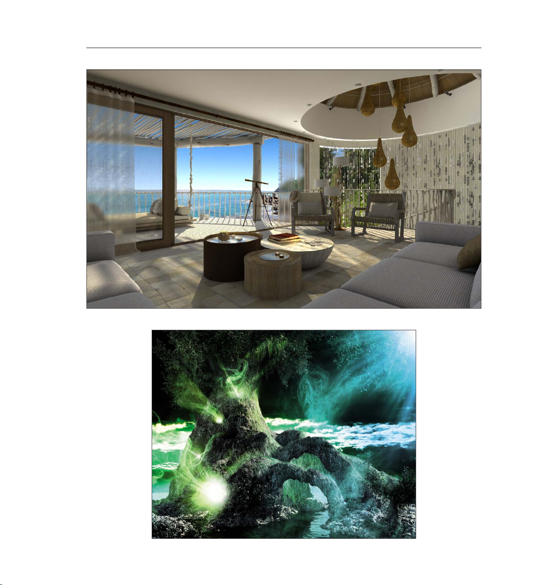
1CINEMA 4D R13 Quickstart – Sample Images
© Pavel Kaplun - www.kaplun.de
Page 6
2 CINEMA 4D R13 Quickstart
Welcome to CINEMA 4D R13
After you have worked through this tutorial you will have a good basic user knowledge which you can apply to
future projects. In this Quickstart manual you will be asked to open certain files for demonstration purposes.
These can be found on your Goodies DVD or on the MAXON homepage on the download / documentation page.
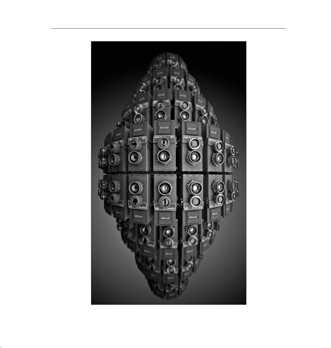
© www.station-nullzwei.de
1. Introduction
To make working with this Quickstart easier, instructional text and tips have been underlain with color for
easy recognition.
Instructional text is highlighted in blue.
If you make an error in working through one of the tutorials, these colors will make it easier to locate
instructional text and tips when trying to nd the location at which you may have made the error.
Page 7

3CINEMA 4D R13 Quickstart – Interface
No matter if you’re just checking CINEMA 4D out or if you already own your own copy of CINEMA 4D, you
already know about the incredible things CINEMA 4D can do. We have been working very closely with our
customers for several years now in order to satisfy their needs and wishes. This has lead to the creation and
introduction of new functionality, according to their needs. These ideas and concepts are then creatively
implemented to satisfy the needs of our customers and those of the 3D markets.
No matter if you work in the field of print, advertising, design, visualization or film, CINEMA 4D gives
you all the tools you need to make your ideas reality. The intuitive interface and the ease with which
CINEMA 4D can be learned makes entering the versatile world for 3D a snap. CINEMA 4D places a link
between your job or hobby, and your creativity in the palm of your hand. You can create what your
fantasy demands. CINEMA 4D will be your dependable partner.
Page 8
4 CINEMA 4D R13 Quickstart – Interface
2. General Information / Interface
CINEMA 4D Release 13 offers many new functions that will again speed up and improve your workflow.
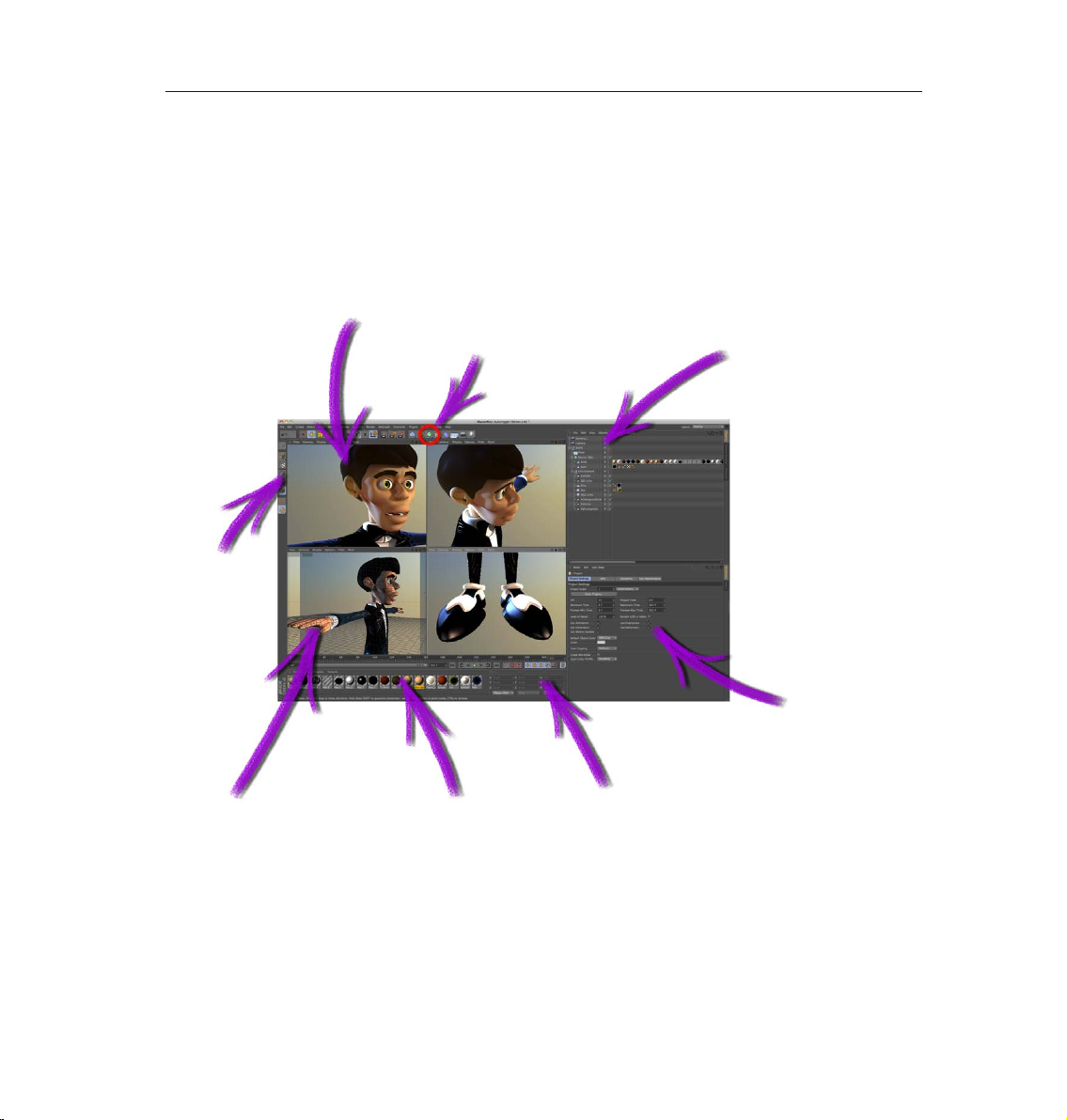
Let ’s start with the most important step - starting CINEMA 4D. Afte r star ti ng CIN EMA 4D you will see an image
similar to the following screenshot:
Rendered Viewport
Icon Palette (tools)
Icon Palette
(modes)
Object Manager
Viewport
(perspective view)
Material Manager
Attribute Manager
Coordinates Manager
Page 9
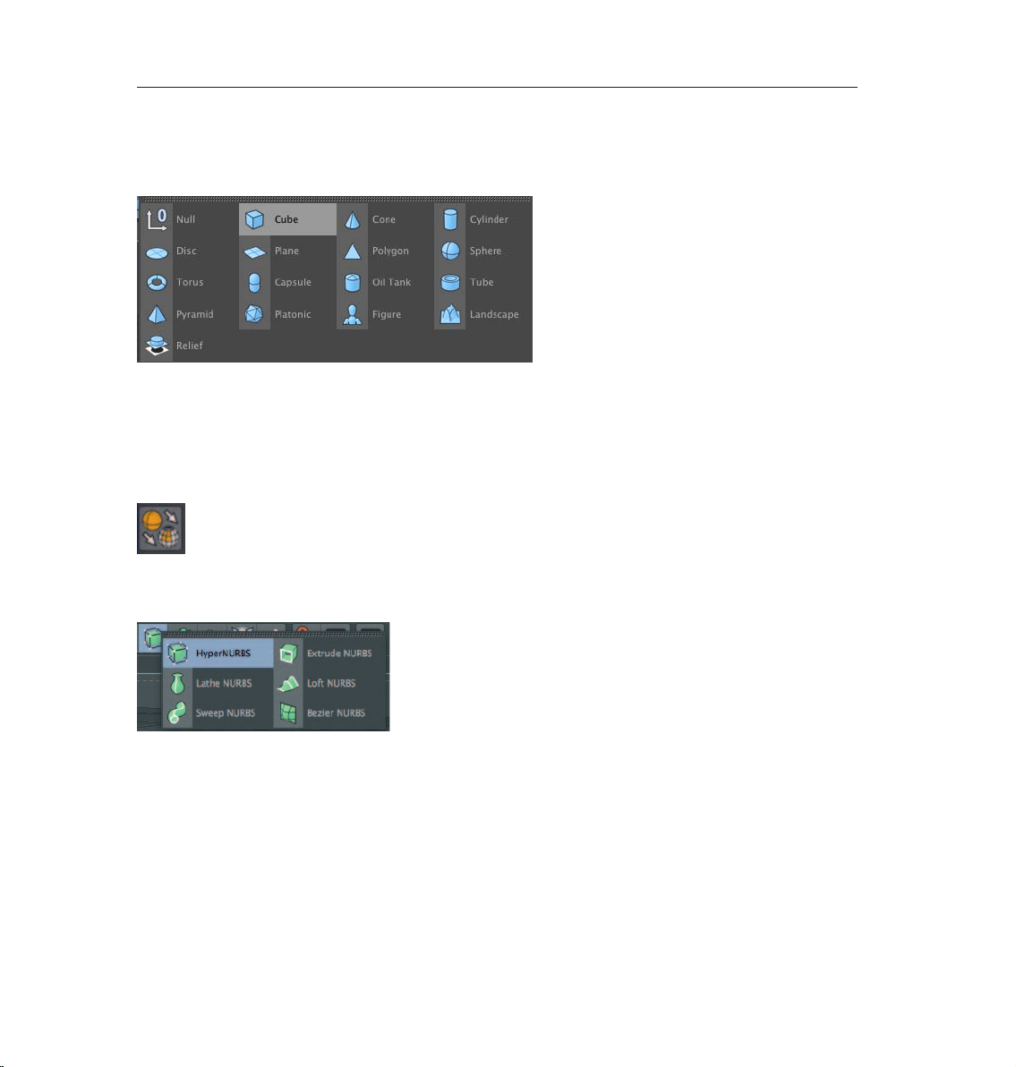
Clicking on the light blue Cube icon opens the parametric object group selection window, which contains all
of CINEMA 4D’s available parameteric objects. It contains all of CINEMA 4D’s available predened parametric
objects.
Click on the second icon to create a cube. Click and hold to see all available parametric objects. Note: After
an object has been initially created it is a parametric object. An object can only be modified as a whole and
not its individual surfaces (an exception are special deformers from the Deformer menu). Before you begin
modeling, the parametric object must be converted to a polygonal object. To do so, select the object you want
to convert and run the Make Editable command by pressing the c-key on your keyboard. You can now move or
modify individual points and surfaces.
Two icons to the right of the Cube Primitive symbol (black cage with white points and turquoise inner) are the
NURBS objects. The most important of these is the HyperNURBS object.
5CINEMA 4D R13 Quickstart – Interface
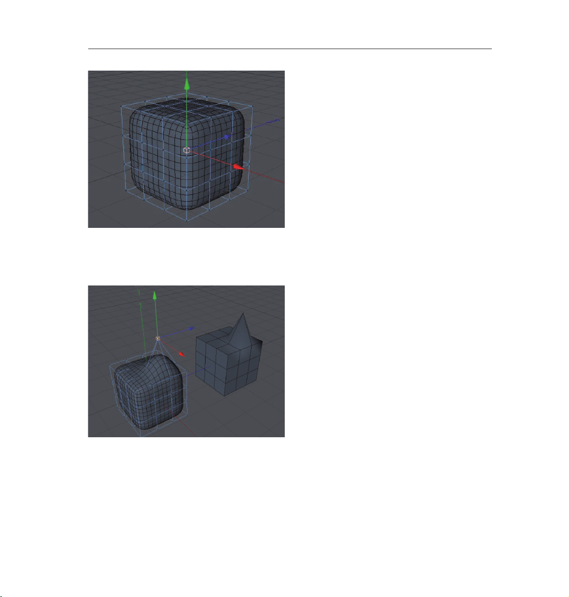
If a polygon object is a sub-object of a HyperNURBS object it will be virtually subdivided to a higher
degree. Visually it will be comprised of many more smaller polygons than before the subdivision (the object
automatically looks softer / rounder). As you can see in the next screen shot: The outer mesh (light blue)
shows the polygon cube’s actual subdivision.
The ner inner mesh (blue) shows the subdivision of the HyperNURBS objec t. Change the cub e‘s display mode
by selecting (deactivating) Options / Isoline Editing in the Viewport’s menu and switching to Gouraud Shading
(Lines) in the Editor’s Display menu. In the end it’s up to you how you want your objects displayed in the same
menu. Then switch to the Use Polygon Mode in the left Icon Palette. However, for this tutorial, this is the most
effective way to show the effect HyperNURBS objects have on polygonal objects or primitives since it shows
how the cube is subdivided and the final result is therefore also easier to visualize.
Page 10
6 CINEMA 4D R13 Quickstart – Interface
The advantages, especially in modeling, are obvious. Since the object contains few points (edges / polygons)
that can be edited it remains very manageable. You can drag just one point of the original wire frame and the
HyperNURBS mesh, with its ner subdivision, will follow the point being dragged (The image below shows the
same Cube object - one with HyperNURBS and one without).
If the polygon object were made up of such fine subdivision modeling, it would be much more complicated.
You would pull one point and only one point would be moved. All other surrounding points would retain their
position. You would have to move each one individually in order to achieve the desired shape.
Page 11

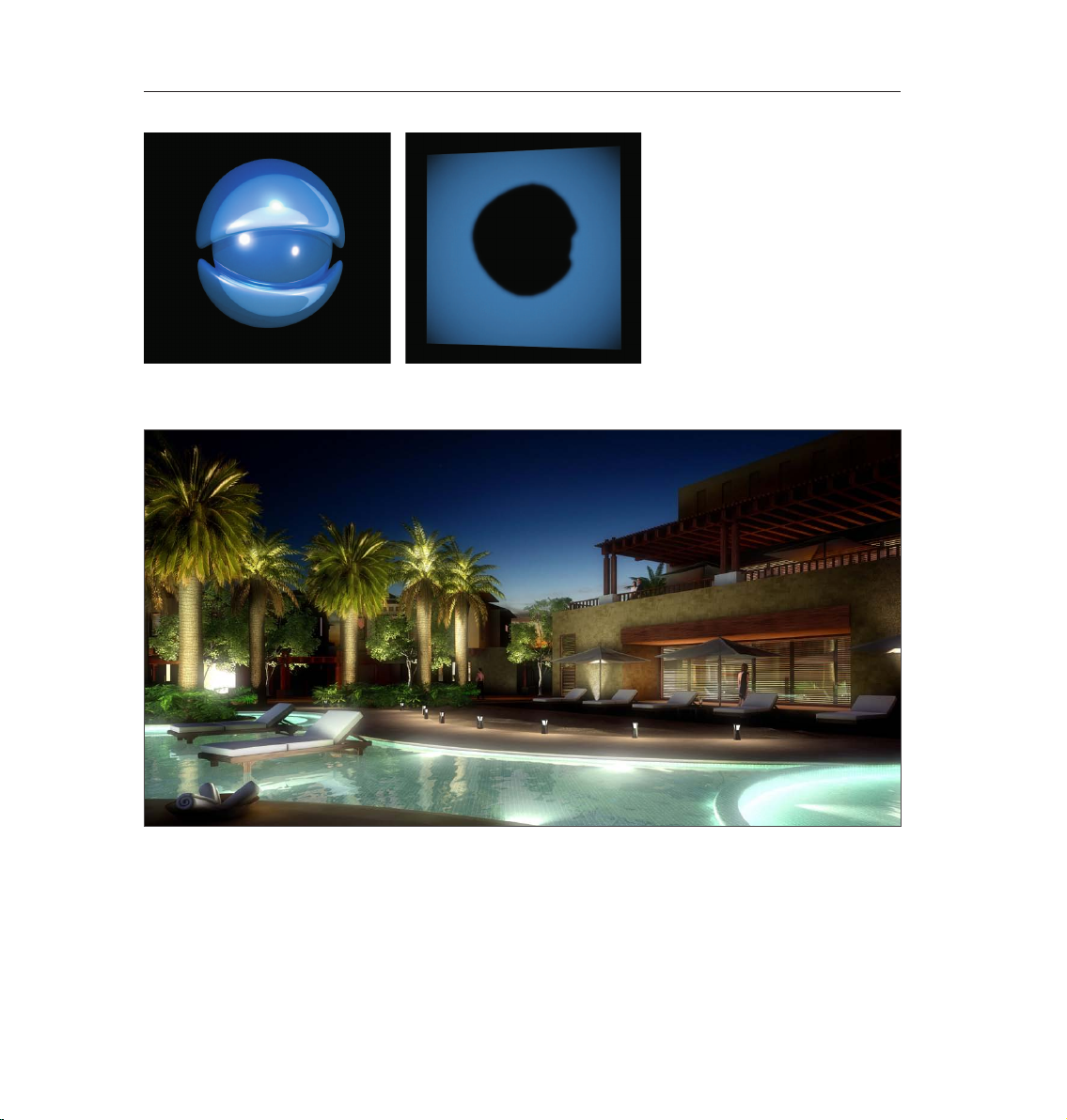
3. Sample Images
7CINEMA 4D R13 Quickstart – Sample Images
© Raphael Rau - silverwing-vfx.de © www.kingcoma.com
© www.bediff.com
Page 12
8 CINEMA 4D R13 Quickstart – Sample Images
© tectonic - www.tma-1.co.za
© www.bediff.com
Page 13
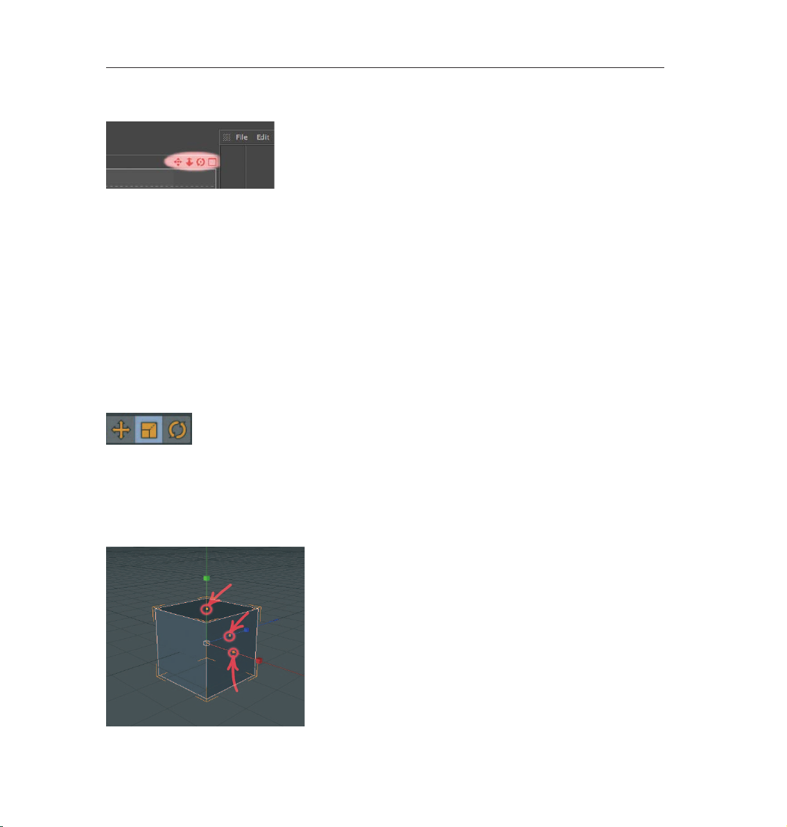
We will continue with navigation in CINEMA 4D.
The rst symbol (click – hold – move mouse) moves the view. The second symbol (foreshortened double
arrow) lets you dolly in and out and the third (curved arrows with a dot in the center) lets you rotate the
scene. Selecting the little rectangle to the right will divide the entire view panel into four views, giving you
multiple viewports to use. Each of the four views has its own little rectangle which, when clicked, enlarges the
respective window. Create a new scene (main menu: File / New) and subsequently a new Cube in that scene.
Zoom out a little and select the word Cube in the Object Manager. The cube’s axis will be visible in the editor
window.
Each of the axis‘ arrows can be selected and dragged in its corresponding direction. This prevents the object
from being dragged in the wrong direction in the editor view. It is often impossible to see in which direction
an object is being dragged in a 3D view. A similar method of moving an object in a single direction is to lock a
specic axis in the command palette. This prevents an object from being moved in the direction of an axis that
has been locked unless you click and drag one of the object’s own axis arrows. These objects are not locked.
Select the Cube object and then click on the Scale function at top.
9CINEMA 4D R13 Quickstart – Interface
The ends of the axis‘ arrows have changed from arrows to boxes. Dragging these boxes will scale the object
al o ng th at par ticu lar ax is. Pa ram etr i c obj e c ts (n ot co nverte d poly gon ob jects) wi ll dis pla y lit tle or ange handl e s.
Important: If you are in Edit Point Mode or Edit Polygon Mode, only the selected points
or polygons will be scaled. In addition, we can no longer see the little orange handles as
a result of having made the cube editable.
They make it possible to stretch and squash the parametric object on the corresponding axis. The nal icon in
this group activates the rotation mode. A series of rings will appear around your object - clicking and dragging
one of these rings will allow you to rotate the object in the respective direction (heading, pitch or bank).
Page 14
10 CINEMA 4D R13 Quickstart – Sample Images
© www.station-nullzwei.de
Page 15

4. Quick Tutorial – Materials
A well-modeled object can make a medi ocre impres sion if the rig ht textures aren’t used. Textures give a model
color, highlights, structure and other important surface properties. A texture placed into the Bump channel,
for example, gives the object’s surface an uneven, bumpy look without actually altering the geometric
structure. This effect can be used to imitate skin wrinkles, scars or the surface of an orange. The displacement
channel works in a similar fashion, only that it actually does change an object’s geometric structure. Using
the Luminance channel you can give an object’s surface a self-illuminating property or integrate a subsurface
scattering effect (sub-surface scattering) which lends the surface a slight translucent / reective look, like
human skin or candle wax, for example. In short: Textures have the same signicance as the outer shape of
an object because they are necessary for achieving the desired atmosphere, coloring and surface structure.
We will begin with a brief introduction to the individual material channels:
Color: This is where the material’s color or the base color for the texture is set.
Diffusion: This channel makes your texture irregular. Through the application of a shader or a texture
your object receives a dirty or dusty look. If desired it can also influence the Specular, Reflection and
Luminance channels respectively.
Luminance: The material is given an illuminative property which is also taken into account in the
Global Illumination calculation.
Transparency: This is where you determine the material’s transparency.
Reflection: Gives the material reflective characteristics.
Environment: A texture is used to simulate an environment reection.
Fog : This channel lets you apply a fog property to a material.
Bump: Uses an optical trick to translate light and dark elements of a texture or a shader to simulate
the height and depth of an uneven surface. Scars, wrinkles or scratches can be simulated using this
channel.
Normal: This channel is meant for use with normal textures. Normals give a low-res polygon object
a hi-res look when RGB textures containing the required properties are applied. This lets a hi-res
polygon object be replaced by a low-res object, thus saving a lot of render time and offering the same
visual result.
Alpha: A texture’s transparency is determined by a material’s light and dark areas. Black equals a
transparency of 100% and white makes it opaque.
Specular: This determines a material’s specular properties.
Specular Color: This determines the color of the material’s specularity and can be inuenced by
a texture.
Glow: Gives the object a self-emitting glow.
Displacement: Deforms an object using light and dark values (calculates differences in height). Do not
confuse this with the Bump channel which only imitates an uneven surface.
11CINEMA 4D R13 Quickstart – Materials
Page 16
12 CINEMA 4D R13 Quickstart – Materials
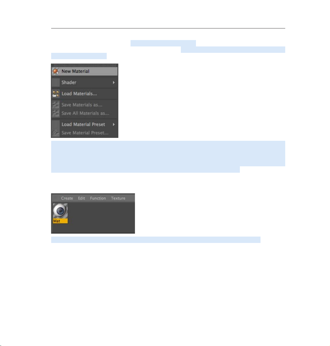
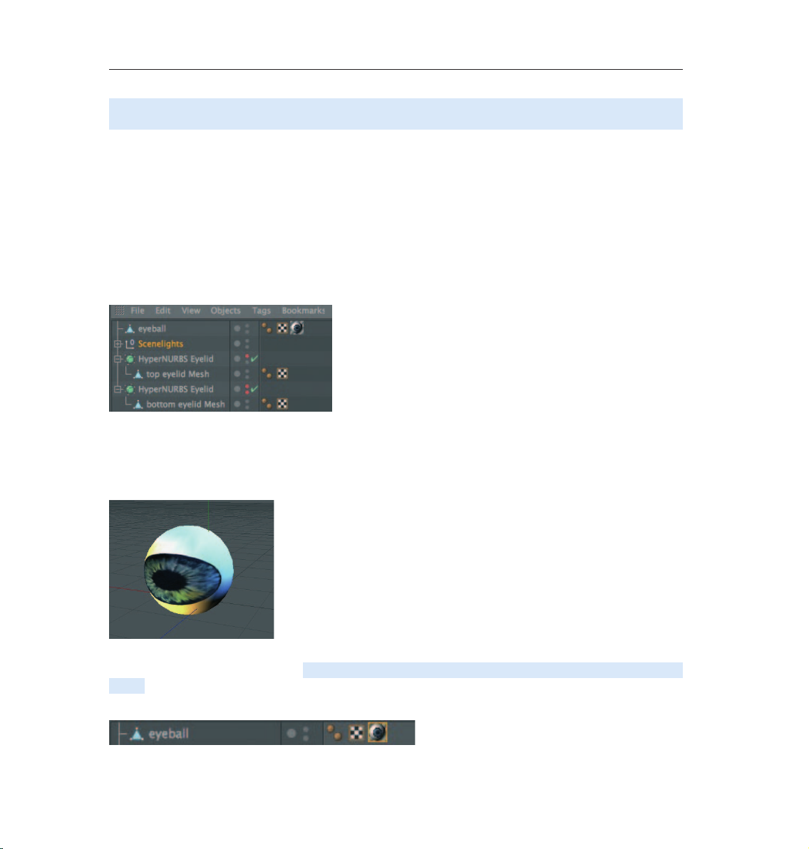
We will now create our own material. Open the QS_Material.c4d file. You can see in the Object Manager to the
right that the object does not yet have a texture applied to it. Click on CREATE / NEW MATERIAL in the Material
Manager at the lower left.
A standard material has been created. If you click on this material its properties will be made visible in the
Attribute Manager to the right. In the Basic tab you can determine which channels should be activated for this
material. Go ahead and activate the Bump channel. As soon as you have done that a new tab will appear in the
Attribute Manager for the Bump channel. Now click on the Color tab and load a texture into the material by
clicking on the small arrow next to Texture. Choose Load Image and load Iristexture.jpg.
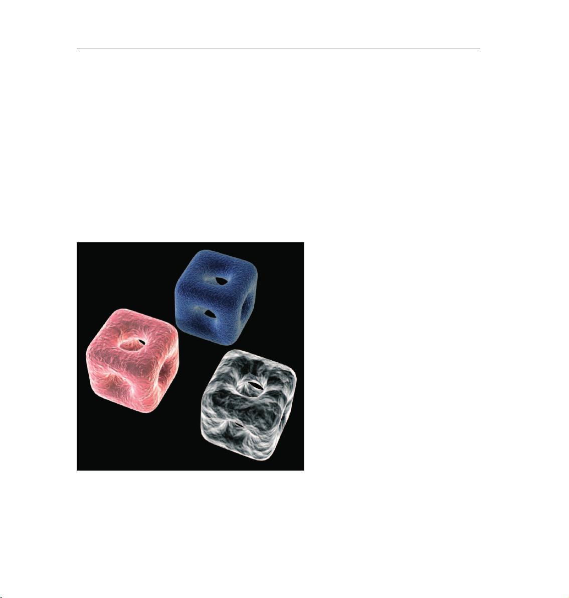
In the mini-preview of the Material Manager at the lower left of your screen you will see the texture displayed
as soon as it has been loaded. This gives you a good overview of the materials being used in the scene.
Repeat this procedure for the Bump channel and load Iristexture_bump.jpg into the channel. This JPEG
contains the grayscale version of the iris texture which we need to create a relief effect for the surface. You
can also choose Filter (click on the small light gray arrow next to the word Texture in the Bump channel) and
load th e color texture here and set its saturatio n to -100%. This saves you from having to load a second image.
The bright areas of the image will later appear to be raised on the object and the dark areas of the image will
appear to be somewhat indented.
A true deformation of the object will only take place in the Displacement channel. The Bump channel does not
alter the polygon’s surface but uses an optical illusion to give the surface its structure.
Page 17
13CINEMA 4D R13 Quickstart – Materials
Click on the material in the Material Manager with the left mouse button and drag it onto the Eyeball object in
the Object Manager (when you drag the material over the object you can let go once the arrow points down).
Alternatively you can drag the material onto the desired object (the eyeball) directly in the Editor. Just make
sure you drop the material onto the correc t objec t if there are several in the scene or in close proximity to one
another. You can check in the Object Manager to make sure the material was dropped onto the correct object
- the material icon will appear next to the object onto which it was dragged.
You have probably noticed that the eyeball brightened somewhat after you applied the material but you aren’t
able to see the actual texture. We still have to change the offset properties and the mapping size so the
texture will be aligned properly on our object. At the moment the actual image of the iris is lying distorted on
the right side of the eyeball. You can check this by making both HyperNURBS eyelid objects invisible for the
editor. To do this double-click on the top small gray dot to the right of the object in the Object Manager (until
it turns red).
Double-click on the dot again and it will turn green, which makes the objects visible again independent of the
visibility settings of any parent object. The dot directly below has the same function except that it affects the
rendering.
Once you have made the eyelids invisible and have rotated the view a little the eyeball should look as follows:
Switch the visibility of the HyperNURBS objects back by clicking again on the dots next to the object in the
Object Manager, making them gray. Click on the Texture tag at the right of the Object Manager next to the
object. It’s the material that we applied to the eyeball. You can recognize it in the mini preview of the texture
in the Object Manager.
Page 18
14 CINEMA 4D R13 Quickstart – Materials
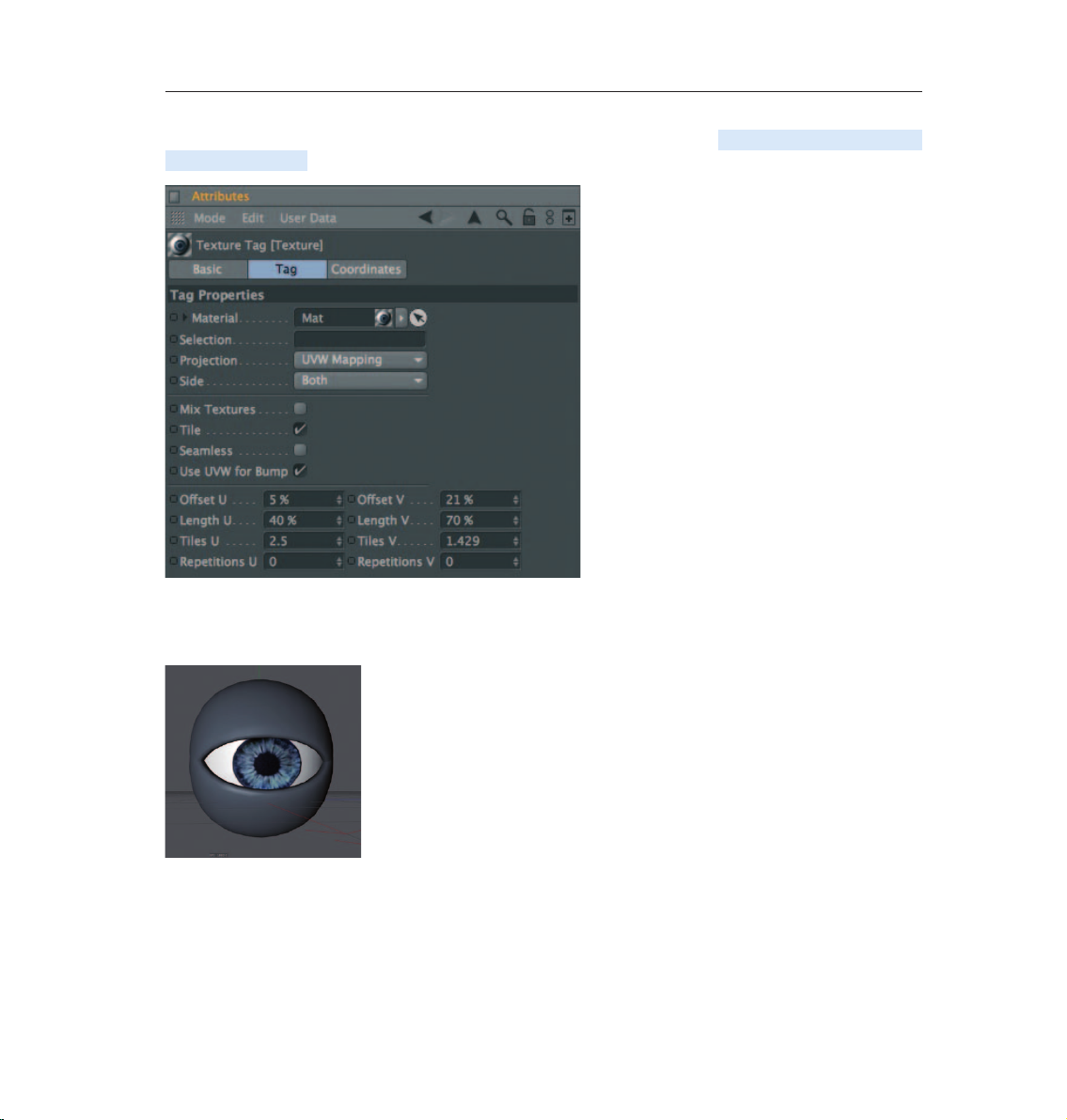
Once you have selected it you will see its parameters in the Attribute Manager. Adopt the settings you see in
the next screenshot:
We have just aligned the texture on the eyeball mesh by changing the Length U and Length V parameters. The
offset setting put the texture in the correct position. If you rotate your view again you will see that the iris
texture is positioned correctly.
Tip: If you want to undo an accidental change to the view just press Ctrl+Shift+Z (Mac:
Cmd+Shift+Z). This function is useful if you have inadvertently rotated the perspective
view instead of the editor view. You can also select view/undo view in the main menu of
the editor view. The texture will complete our model. Experiment with the parameters of
the individual channels to find out how they affect the material. At this point we would
like to offer you a few additional tips.
Page 19
15CINEMA 4D R13 Quickstart – Materials
If you own CINEMA 4D Visualize or CINEMA 4D Studio, you can render human skin realistically using Subsurface
Scattering. By placing this shader in the Luminance channel (click on the small arrow next to Texture and
select Subsurface Scattering from the Effects menu) the effect is created when rays of light meet a slightly
transparent object. Some rays infiltrate the object further and are dispersed, others are directly absorbed or
bounce off.
Further possible uses for this effect would be for materials such as plastic, milk, candle wax or gurines
made of jade. You can load black & white textures into the alpha channel to inuence the material based on
the texture’s brightness, similar to the way you would use them for the bump or displacement channels. The
texture’s black areas would be rendered with a transparency of 100%. As the texture becomes brighter the
transparency is reduced accordingly. White would have a transparency of 0%
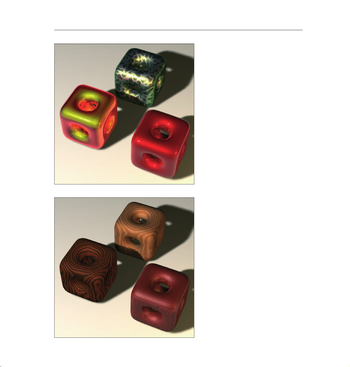
If you choose Shader instead of New Material under Create in the Material Manager you will see a list of 3D
shader presets. The advantage of these shaders is that you don’t have to worry about mapping your texture
or seams in your texture because a 3D shader will be calculated for the 3D space. Here are a couple described
in detail:
Cheen: Generates an electron microscope effect good for the depiction of bacteria or mites.
Page 20
16 CINEMA 4D R13 Quickstart – Materials
Danel: Very good for simulating high-gloss nish.
Banzi: Lets you depict various types of wood.
Page 21
17CINEMA 4D R13 Quickstart – Materials
Banji: Calculates complex lighting situations with glass and even makes rear-projection (shadow casting) on
partially transparent materials such as rice- or canvas paper possible.
© christoph mensak, brown_eye_architects@gmx.de
Page 22
18 CINEMA 4D R13 Quickstart – Lighting
© Christoph Mensak - brown_eye_architects@gmx.de
5. Quick Tutorial – Lighting
If you are already familiar with lighting a scene in the real world then you will feel right at home with the
CINEMA 4D light objects. They can do everything real lights can do – and quite a bit more. In this tutorial we
will set up a 3-point lighting arrangement. This type of arrangement is used often in portrait photography to
achieve an even lighting and is an excellent method for lighting an object quickly and professionally in the 3D
world.
Open the file QS_Light.c4d and adjust your editor view so the entire figure is visible to you.
We want to light up our little character. Create a oor object (Create / Environment / Floor) and position it so
the figure is standing on it.
Page 23
19CINEMA 4D R13 Quickstart – Lighting
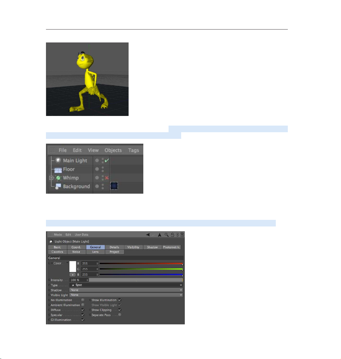
A 3-point lighting arrangement begins with setting a key light. As the name suggests, this light emits the main
lighting for the scene and will cast the main shadows. Create a light object (Create / Light / Light). Name it
Main Light (double-click on the name) in the Object Manager.
CINEMA 4D has several different types of light sources. The Omni light will always be created by default. An
Omni light emits from its center in all directions. For our key light we will need a spot light which we can aim
directly at the object.
To make the key light a spot simply go to the Attribute Manager and switch the light from Omni to Spot.
Page 24
20 CINEMA 4D R13 Quickstart – Lighting
Now our light source has been transformed to a spot. A spot acts like a flashlight. CINEMA 4D offers spots
with square and round cones of light. This cone is visible in the editor and can be manipulated. Now we will
aim the spot at our figure.
Position the light at the following coordinates in the Attribute Manager:
X= 300
Y= 580
Z= -30 0
at an angle of
H= 45
P= -45
degrees (enter the values and click on the Apply button).
Render the scene (Cmd / Ctrl + r).
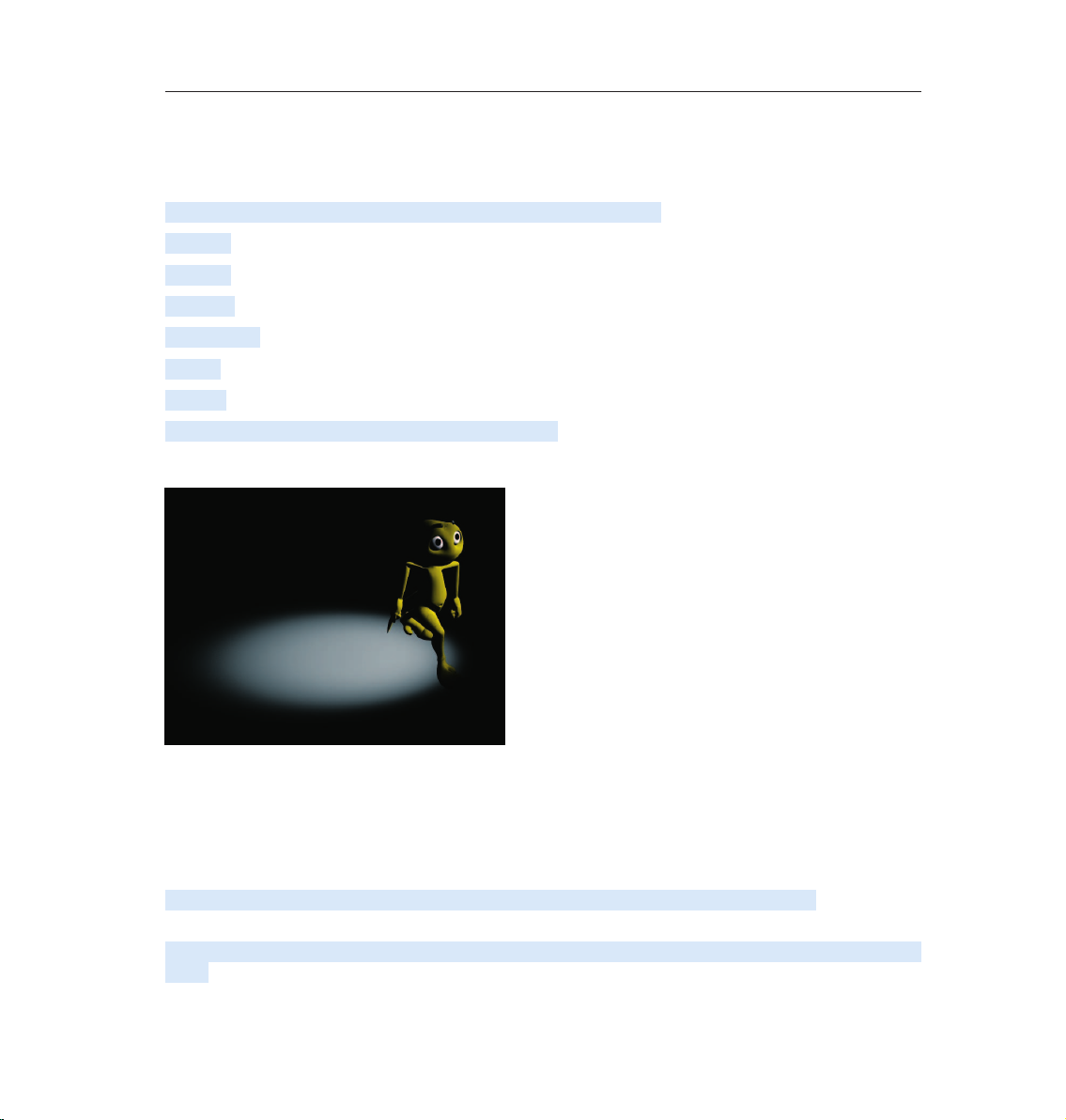
The light now falls at an angle onto our object (If this is not visible in the Editor it may be due to the fact that
you r display mode is set to Quick Shadin g (uses a single default light source) instead of Gouraud Shading (uses
all scene lights)). Of course the exact position of the light is strongly dependent upon the camera’s angle.
Unfortunately the light is not casting a shadow, letting the gure look like it’s oating. CINEMA 4D’s lights
have an advantage over real light in that you can choose which kind of shadow, if any, they should cast - a plus
for any studio photographer.
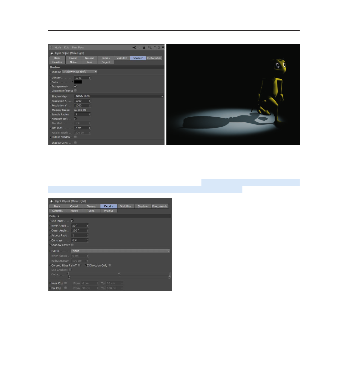
In the General menu of the Attribute Manager, set the light’s shadow to Shadow Maps (Soft). We don’t want
the shadow to be completely black so we’ll make it a little transparent.
In the Shadow menu, set the shadow density to 50%. Select 1000 x 1000 as the shadow map. Render the
scene.
Page 25
21CINEMA 4D R13 Quickstart – Lighting
CINEMA 4D offers three types of shadows: Raytraced (Hard) – a shadow with sharp edges, Shadow Maps (Soft)
– a shadow with soft edges and Area – a shadow that becomes softer the further it’s away from the object,
resulting in the most realistic shadow effect. Try the other two shadow types. Careful, the area shadow can
take a long time to render! The larger shadow map allows the shadow to be rendered more accurately.
The light’s cone is a little too small. We will change this as follows: Switch to the details menu in the Attribute
Manager and set the Inner Angle to 30 degrees and the Outer Angle to 100 degrees.
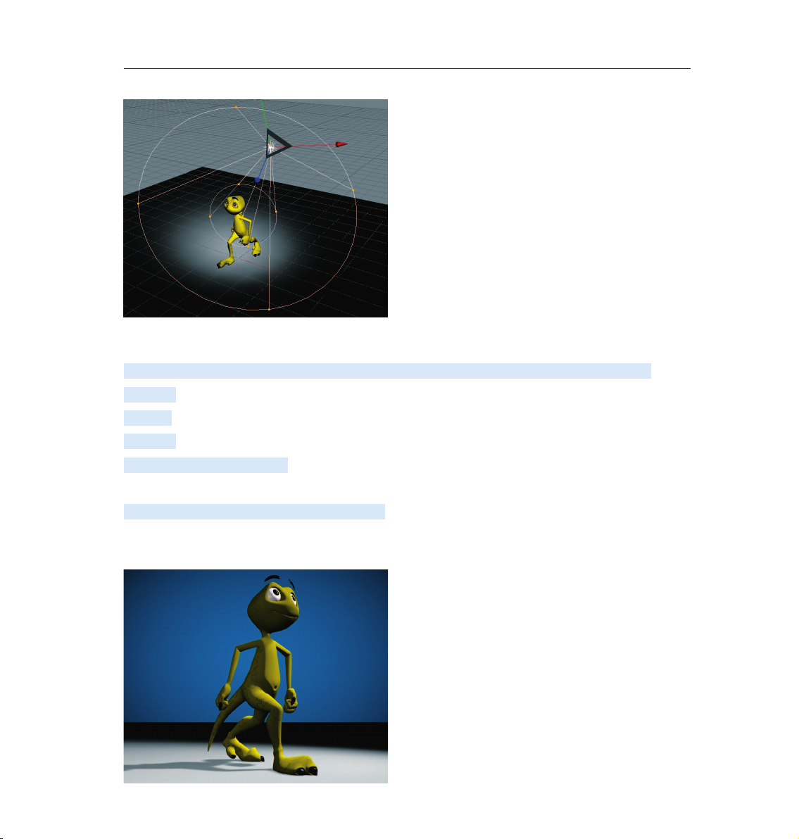
You will see the result in the editor right away. You can also edit the light’s cone by dragging the orange
handles. If your graphics card will support it you can set the editor’s display mode to Enhanced OpenGL with
activated shadows. (Viewport: OPTIONS / ENHANCED OPENGL) Generally speaking, OpenGL offers a much
more precise depiction of your scene and gives you an impression of how the shadows will fall).
Page 26
22 CINEMA 4D R13 Quickstart – Lighting
Now we’re happy with our key light. Next we will create a more even lighting by brightening our gure a little
from the other side.
Create another light source in the scene and name it Brightener. Place it at the following coordinates:
X= -36 0
Y= 225
Z= -23 0
Select Area as the type of light.
Since the brightness of the lights in the scene is additive, we must dim the brightener a little.
Reduce the Intensity in the General menu to 40%.
This area light illuminates the gure from a different angle and softens the contrast somewhat. It won’t cast a
shadow since this would cause crossing of the shadows and make the object look bad.
Page 27
23CINEMA 4D R13 Quickstart – Lighting
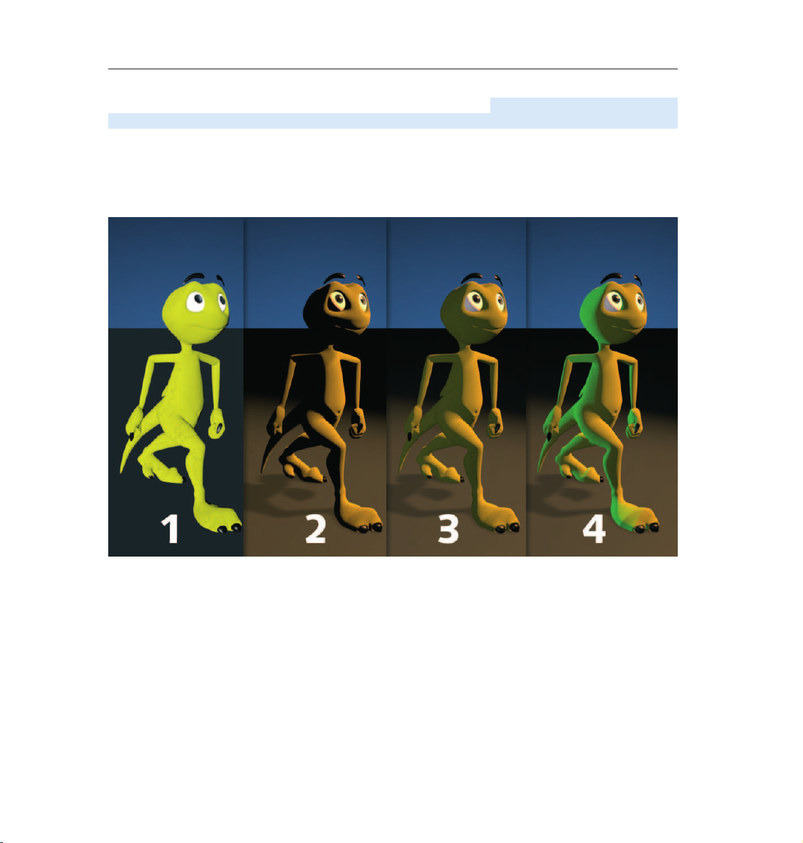
The scene is now pretty evenly lit, but we want to give it a little more pep. Create another light source, name it
Color and, in the Attribute Manager, set its type to Innite. Set its color to turquoise and set its H angle to -160.
The position of an innite light is irrelevant since it always lights your scene in the direction of the Z axis. This
is why we will leave it at the point at which it was created. It gives our Amphibian an interesting color edge and
sets him off of the background a little.
Your scene’s mood can be changed by simply changing the color of some of the lights used.
That completes our classic 3-point lighting arrangement. Now the real work starts. If the scene has a
background, which is often the case, it will have to be lit as well. With the proper use of omni lights details in
the scene can be brought to light very nicely. But don’t overdo it. With good lighting, less is often more. Only
add lights when necessary and if the scene can actually benefit from them. Two more tips before we end: If you
have several lights in a scene and are not sure which light is lighting what, simply turn off (green check mark)
all other lights in the Object Manager. The light which remains will be the only one visible.
One trick you can use while aiming lights is to view the scene from the perspective of the light. Select the
desired light in the Object Manager and activate Set Active Object as Camera in the editor view’s Cameras
menu. Selecting this option lets you view the scene from the point of view of an active object, in our case the
light. Moving the editor view will automatically change the position of the light when in this mode. This way you
can see how the change of position of the light affects the lighting of the object in real-time (Gouraud Shading
must be active in the editor view). Once you have reached the desired angle and position you can return to the
editor view by selecting Use Camera / Default Camera from the Cameras menu.
Page 28

24 CINEMA 4D R13 Quickstart – Sample Images
© Dave Davidson - www.max3d.org
Page 29
25CINEMA 4D R13 Quickstart – Sample Images
© Benedict Campbell, www.benedict1.com
Page 30
26 CINEMA 4D R13 Quickstart – Lighting
6. Tips & Tricks
© Raphael Rau - silverwing-vfx.de
CINEMA 4D has been able to build a large community of users around it who are more than happy to help
newcomers in any way possible, be it through the use of home-made tutorials, directly in one of the many
forums or by offering free models, plugins, expressions or textures.
One of the main sources of information, of course, is the MAXON web site www.MAXON.net.
Here you will nd news, interesting projects that were done with CINEMA 4D, an extensive CINEMA 4D link
library and even a form for questions for our support department.
Flipping through books which don’t have anything to do with computer graphics can also be helpful. 3D is
a complex eld in which many of the classic arts and techniques are combined. Books about photography,
lighting, direction, acting, image creation and painting should be part of every serious 3D artist’s library. In
addition, you will find a wealth of information on all of these topics online.
Since the Internet is always changing, doing a search for CINEMA 4D in various search engines would be a
good idea.
The Internet is a good source for finding models. Through its special image search function you can find
photos or drawings of practically any object.
Page 31

27CINEMA 4D R13 Quickstart – Lighting
Even mail order catalogs can be a great source of information on how an object is supposed to look.
Textures are all over the Internet as well. Note that almost all image are copyright protected and cannot be
used commercially. Taking your camera and photographing textures yourself is even better. Inspiration is
everywhere. You can build your own texture archives in no time.
Try to get away from the technical point of view. Learning a software is only a matter of time. A good 3D artist
has the ability to use software as a tool that helps him realize his ideas. The real creativity lies with the idea,
not the software. So when you create your next scene don’t worry so much about creating the perfect object.
Concentrate rather on how you can make a harmonious composition with this object with a fitting theme
and proper lighting. Also, think about the message you are trying to send to the viewer. The same goes for
animators. A technically perfect animation is a great achievement but it will put your audience to sleep if the
concept is bad. It’s not so bad, on the other hand, if your animation is a little bumpy and imperfect but your
story touches the viewer.
We hope this manual will help you master the technical part of 3D graphics. What you do with what you’ve
learned is in your hands.
© Jonathan Reeves - www.jr-architecture.co.uk
Page 32

28 CINEMA 4D R13 Quickstart – BodyPaint 3D
BodyPaint 3D
This is the BodyPaint 3D tutorial. In this tutorial we will explain the most important functions in order to
give you a running start in the world of 3D painting. Even if BodyPaint 3D appears to be difficult at first, you
will soon notice how intuitive BodyPaint 3D really is. In this tutorial we have also put an emphasis on a fast
learning curve and a high degree of user friendliness for this application. Let’s start with its structure.
© www.segnoprogetto.it
1. Introduction
BodyPaint 3D will revolutionize the way you work with textures in such a way you will wonder how you ever
got along without it! With BodyPaint 3D you can paint your models as they are: in 3D. This is what BodyPaint
3D, the revolutionary way to texture objects, is all about. In addition, BodyPaint 3D lets you paint in several
texture channels at once, and thanks to RayBrush even directly on the rendered image itself. Projection
Painting is a tool we have integrated that makes it possible to paint on complex objects without distortion.
Using the UV-tools you can relax and stretch your UV-mesh, no matter how complex it is. Put simply, a UVmesh is a second impression of a polygon mesh that projects the texture onto a polygon object. The days of
2D texturing are over and you can nally concentrate on what’s important in texturing: creativity. Everything
that took up so much time with 2D texturing is now done by BodyPaint 3D and you can deliver your projects
faster. Let’s move to the user interface (BodyPaint 3D is a component of CINEMA 4D and can be activated by
simply selecting BodyPaint 3D from the CINEMA 4D Layout menu at the top right of the GUI).
Page 33

2. General Information / Interface
First take a look at the screenshot below:
29CINEMA 4D R13 Quickstart – BodyPaint 3D
6. Icon Palette
(modes)
5. Object Manager
and color settings
1. Rendered Viewport
4. Attribute Manager Window
2. Texture Window
(UV Mesh Editor Window)
3. UV Manager
Here you see on e of the two standard layouts: BP UV Edit. The second layou t (B P 3D Pai nt) is set up in a similar
fashion, only without the UV-mesh editor window which gives you more room in the editor window to paint.
Page 34

30 CINEMA 4D R13 Quickstart – BodyPaint 3D
1. Viewport
Here you can see the object you will be painting. You can rotate, move and zoom the window as needed. The
RayBrush mode lets you paint directly onto the object in the rendered version of the view. This gives you
control over the amount of color applied and can see right away how a new color looks on the object.
2. Texture Window (UV Mesh Editor Window)
This is where you edit your UV-mesh. You can relax and restore your UV-mesh. If you use the UV-Manager’s
UV-tools you can watch how the texture relaxes. You can also watch the color application process in this
window, which will then be visible in the editor window right away.
3. UV Manager
Th e UV-Ma n ager le ts yo u resto re th e UV- m e sh usi ng an alg o rith m . It rec ogni zes la yer ed poly gons an d atte m pts
to relax the UV-mesh for optimal placement over the entire surface and, if necessary, new placement. All
remaining relaxation can be adjusted manually.
4. Attribute Manager Window
Different tabs display different brush types and their respective attributes as well as the UV Manager’s UV
tools.
5. Object Manager, Material Manager and color settings
The Object Manager, Material Manager and Color Manager are tabbed in the lower left corner of the interface.
As in the standard layout, the Object Manager displays all the objects in your scene.
The Material Manager in this layout has expanded functionality, allowing you to manipulate individual material
layers and paint on multiple channels at once.
Within the Color Manager, you can set up the color or texture that you’d like to paint within each channel.
6. Icon Palettes
The command palette contains the Paint Wizard, the Projection Painting and many other tools (that you’re
probably used to using with 2D paint programs). The BodyPaint 3D Wizard eliminates the need to manually
create a texture including the UV-mesh. It also calculates the texture size and channels. Without these
bothersome preparations you can begin painting right away.
Page 35

31CINEMA 4D R13 Quickstart – Sample Images
3. Sample Images
We’ve reached a part of the tutorial for which words are not necessarily needed. Simply take a look at the
following images.
© Patrick Eischen, www.patrickeischen.com © HH Vision Architekturvisualisierung
© Fredi Voß www.fredivoss.de
Page 36

32 CINEMA 4D R13 Quickstart – BodyPaint 3D
Now we’ll get to the heart of this tutorial. Open the le QS_BP3D_Start.c4d. Say hello to Claude, our guinea
pig for the day. In the course of this tutorial we will alter the color of his right eyelid a little and apply a Bump
layer to give a more elephant-like look to his skin.
Select the predened standard layout BP UV Edit at the top right of CINEMA 4D’s main editor window. Click
on the BodyPaint 3D Wizard Icon so we can make the necessary preparations to the texture (brush symbol
with white stars).
Click on Deselect All in the window you just opened and apply a white check mark to the eyelid right object only.
We have just determined that a texture should be created only for the right eyelid object. Click on Next. Leave
the settings in the next window the way they are. The selection Single Material Mode would create a texture
for each object individually. If the box is checked all objects will share one texture surface. Click on Next again.
In the next window check the Bump channel. The Color channel is selected by default. You can double click the
little gray boxes next to each texture channel and assign each channel a base color.
Since Claude likes elephant gray we will leave the boxes the way they are. Leave the rest of the settings the
way they are and click on Finish, then on Close in the next window. The basic textures have been created and
we can start painting. If you have experience with earlier texturing methods and the time it took to even get
started BodyPaint 3D will seem like a blessing to you. BodyPaint 3D saves you a lot of time. Now let’s move to
the second part of the tutorial: the UV-meshes and the rst brush stroke.
Page 37

33CINEMA 4D R13 Quickstart – BodyPaint 3D
4. Quick Tutorial – First Painting Lesson
At the bottom left of the Material Manager (in the Materials tab) you will nd the textures we just created,
right next to Mat.
This is the default name for a new material. Of course you can rename the material if you like. The rst texture
is the color layer and the second is the Bump layer (at the top of the window you will see the abbreviations
which refer to these layers – C for color and B for bump).
Now Select the Use UV Polygon Edit Tool symbol.
Once you have selected the corresponding texture in the Color channel the UV-mesh should become visible
in the texture window at the upper right. If the mesh is not visible, activate it by clicking on UV Mesh / Show
UV Mesh in the texture window menu. Luck is on our side! Fortunately, the default UV mesh looks pretty good.
The only problem is that the UVs corresponding to the eyelids (highlighted in orange in the next image) are
too small.
Page 38

34 CINEMA 4D R13 Quickstart – BodyPaint 3D
The individual UV-mesh polygons of these eyelid edges take up less texture area than the rest of the polygons.
That’s why a texture placed into the Bump channel appears larger in these places (photograph of elephant
skin, for example). We can do without this, though, since we are painting our own skin structures onto the
surfaces and not using an existing texture. We can counter any distortion we encounter when painting
manually by using Projection Painting. The stroke will maintain its width no matter how the polygon is spread
over the mesh.
Move and zoom the editor window view until Claude’s right eyelid lls the view.
Page 39

35CINEMA 4D R13 Quickstart – BodyPaint 3D
Now select Brush Tool for Painting Textures for applying the color. Set the size to 25 and the Pressure to 40
in the brush’s Attribute Manager…
…and select a pink color in the Color Manager.
If necessary, increase the HyperNURBS subdivision. Activate the Raybrush Render View for RayBrush Painting
in the active view in the Render menu (BodyPaint 3D main menu).
This will render the view and makes it possible for you to control the color application and the look of the
strokes for the final rendering).
Activate Projection Painting (so you can paint without distortion and across any UV seams) and start painting.
Of course BodyPaint 3D supports the use of graphic tablets such as a WACOM Intuos. Painting objects with a
pressure sensitive pen on a graphic tablet is much easier than painting with a mouse.
Page 40

36 CINEMA 4D R13 Quickstart – BodyPaint 3D
Paint along the edge of the eyelid. The eyelid will probably end up looking like this:
If you move / rotate the gure now or click on the Apply the Content of Projection Paint Plane (click and hold
on the Activate/Deactivate Projection Painting button)
you will see how the color was applied to the texture (you can see the recently applied strokes of color in the
window to the right).
You can take the same steps for the Bump layer. We will take you one step further, though, in order to be able
to explain an important function. We will paint both layers at the same time! Select the texture in the Color
channel of the Material Manager. Now click on the icon with the black/orange pencil at the left of the Material
Manager. Select the pencil icon next to the B of the Bump channel as well.
You have now told BodyPaint 3D that you want to paint in both layers at the same time. If you like you can
switch from the standard BP UV Edit layout to the BP 3D Paint layout. This gives you more room to work in
the editor window.
Page 41
37CINEMA 4D R13 Quickstart – BodyPaint 3D
Rotate the view so you can see the eyelid from the top. Activate the Raybrush Render View for RayBrush
Painting mode and set the brush size to 10. Switch to the color layer’s Color menu and set the color to a
medium gray which will be the base color for our eyelid. Now go to the Bump layer’s color preview and set the
color to black (both color layers are located in the Materials tab under the letters C and B + pencil symbol).
When you paint on the object you will notice that both colors are being applied to the object – the gray base
color and the black (to indicate indentations).
If white were the color of the Bump channel it would raise the brush stroke instead of indicating indentations.
The result could look like the following image.
Load the QS_BP3D_Final.c4d le and take a look at it when you have time. Here are some everyday tips with
which you can achieve great results quickly and easily.
Page 42

38 CINEMA 4D R13 Quickstart – BodyPaint 3D
5. Tips & Tricks
A very helpful function can be found in CINEMA 4D’s preferences (Ctrl+E). In the BodyPaint 3D menu you will
find the function Project On Invisible Parts, which, when activated, allows you to paint on both sides of an
object in projection paint mode. Let’s assume you want to color the arm of a gure or sprinkle color on the
entire figure. With this function deactivated you would have to apply the color with this function deactivated,
rotate the arm, apply the color, rotate the arm and, well, you get the idea. When this function is activated you
apply the color in the front view and the color is applied to all surfaces lying behind this surface at the same
time. Just make sure you don’t apply color to objects you don’t want to color when this function has been
activated.
If a texture map does not t correctly at the point where large and small polygons meet (in the case of lowpoly objects that are subordinates of HyperNURBS) set the Tile UV’s function, in the respective HyperNURBS
Object’s Attribute Manager, from Edge Standart to Boundary to Edge. This sends the UV-mesh through the
HyperNURBS algorithm and subdivides it to t the polygon object.
Avoid UV-mesh polygons that meet to a point when applying a noise texture to a Bump layer. The narrower
a 3-sided polygon becomes, the coarser the bump noise channel will be rendered. Of course such a polygon
has much less area for the noise structure at its tip than it does at its center which results in a magnification
effect of the noise structure.
Try to set up each side of a triangulated polygon as an isoscel es . This also goes for 4- point polygons when they
converge into a trapezoid. The more square the polygon the more even the structure will be. It goes without
saying that you need different brushes for different texture looks. CINEMA 4D has a wide variety of brush
types for you to use. Just select the tab Attributes and click on the small arrow on the brush preview.
Here you will nd a wide variety of preset brushes corresponding to natural media and detail effects. You can
also load preset brushes from Adobe Photoshop, and save your own brushes. Just make the changes you want
and click on the Save Brush button.
Now that you’ve gotten a brief introduction to BodyPaint 3D’s painting tools, you can experiment and practice
adding details to your own models.
Page 43

39CINEMA 4D R13 Quickstart – BodyPaint 3D
Page 44
40 CINEMA 4D R13 Quickstart – CINEMA 4D Renderer
© Christoph Mensak - brown_eye_architects@gmx.de
CINEMA 4D Renderer
This is the Quickstart Tutorial for the CINEMA 4D renderer. It will show you many of the CINEMA 4D renderer’s
typical applications and covers some theoretical physics behind the effects.
1. General Information / Interface
As soon as you open the Render Settings (main menu: Render / Edit Render Settings...) you will find
parameters such as Global Illumination by clicking on the Effect... button. If Global Illumination is enabled,
other options will be made available, which allow you to create custom settings for radiosity. A material’s
illumination settings are closely associated with the render settings. These settings let you determine if a
particular material should be rendered with Global Illumination. Further settings can be applied to individual
objects using the Compositing tag.
Page 45

41CINEMA 4D R13 Quickstart – CINEMA 4D Renderer
Caustics (available in CINEMA 4D Visualize and Studio) acts in a similar fashion. The global settings can be
found under render settings. Here you can activate or deactivate surface and volume caustics separately.
Options relating to specific materials can be set in the Luminance channel. In addition, caustics also offers a
third setting. You will nd this in the light object. The use of caustics requires at least one light object. Within
a light’s caustics menu it is possible to determine whether the light source should generate surface or volume
caustics.
Page 46
42 CINEMA 4D R13 Quickstart – CINEMA 4D Renderer
Depth of field, highlight and glow are additional post effects available in CINEMA 4D Visualize and Studio.
You will find them in the Render Settings under Effect. Further settings for depth of field can be made in each
camera’s attrib ute set tings. A post effect will rst be calculated after an image has been completely rendered.
You can imagine it as a layer which is placed on top of the image after it has been rendered.
© Robin Richter www.rr-graphix.de
2. Quick Tutorial – Rendering
You’v e bee n a bus y bee . You have cre ated a scene , set up th e lig hting, anim at ed ob jec ts and assign ed ma te ria ls
to them. Now we want to see the result of all this work. What you have to do is to transform this 3-dimensional
scene into a 2-dimensional image (in the case of an animation it would be an entire series of images). We will
render the images. Open the file QS_Render_01.c4d to work through the following tutorial. CINEMA 4D offers
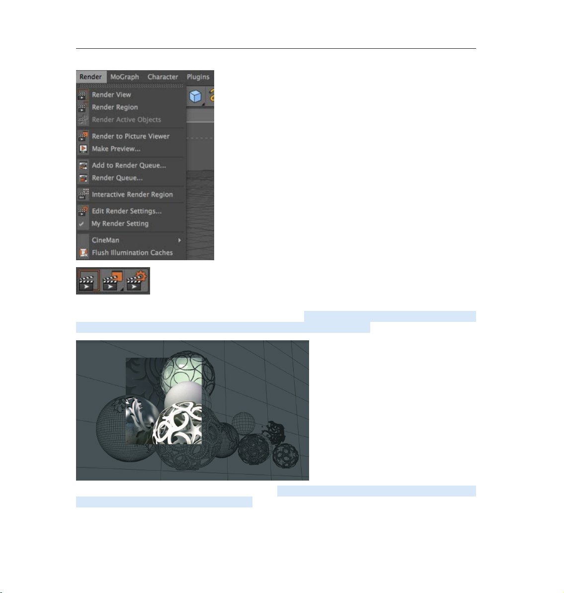
a wide variety of options for rendering your 3D scene in a Viewport:
1. Using the main menu
2. The keyboard shortcut Ctrl+R
3. By clicking on the icon in the editor window (the clapboard farthest to the left)
Page 47
43CINEMA 4D R13 Quickstart – CINEMA 4D Renderer
Use the method with which you feel most comfortable. Often we don’t necessarily want to render the complete
editor view but only a small part of it. This is also no problem. Select Render / Render Region. The cursor will
be transformed into a cross. Drag a frame around the region you wish to render.
The second possibility is to render only a single object. Select the object Master in the Object Manager. Select
the command (Render / Render Active Objects).
Page 48

44 CINEMA 4D R13 Quickstart – CINEMA 4D Renderer
Only the selected objects will be rendered.
Rendering the editor view gives us a quick overview of the scene but it does not offer the possibility to process
this image further, to save it to the hard drive, for example. To save your renders or render a full animation,
select Render / Render to Picture Viewer or press Shift+R. The picture viewer will open in a separate window
in which the scene will be rendered. When the image has been rendered select File / Save As. A further window
will open. Select the appropriate format and confirm with OK.
Of course you can also save a series of images as an animation. To do so, change the Frame Range from
Current Frame to All Frames, and set Format to QuickTime Movie, for example. Rendering to the Picture
Viewer has the additional advantage that you can continue working on your scene if the image should take a
while to render.
Page 49

45CINEMA 4D R13 Quickstart – CINEMA 4D Renderer
You use the Render Settings (main menu: Render / Edit Render Settings...) to determine what our nal image
will look like. Size, quality, single image or animation can be set here.
If your rendered objects appear pixelated at their edges, this is a result of the anti-aliasing settings. This term
refers to how smoothly an edge is rendered. Open the file QS_Render_01.c4d. In the Render Settings menu,
set anti-aliasing to None and render the scene.
You can plainly see pixelation along the wire now as well.
Now set anti-aliasing to Best and render the scene again. All edges have been rendered much smoother
without losing clarity.
To quickly check the scene you can leave the anti-aliasing set to None or Geometry. None renders the edges
without anti-aliasing and very quickly. Geometry renders the image with sufcient smoothing and offers a
good compromise be twee n quality and speed . You can select the bes t quality when you render the nal image.
The Filter menu lets you select the type of anti-aliasing lter.
The parameters you modify/dene in the Output and Save Render Settings menu dep end on the requirements
of your scene.
Page 50

46 CINEMA 4D R13 Quickstart – CINEMA 4D Renderer
If, for example, you render a single image that will be printed with a resolution of 300dpi on a 8.5x11 size page
you should render the image with a resolution of at least 2550 x 3300. If you want to print the image in a
picture size of 3x5, a render resolution of 900 x 1500 will be more than enough.
Animation is a different story. The frame rate, which is also editable in the Output menu of the Render Settings,
plays an important role in animation. The frame rate is the speed at which the animation plays. A frame rate
of 25 means that 25 images per second will be played. If you produce an animation for the European market
you will have to adhere to the PAL standard which uses an output size of 768 x 576 pixels and a frame rate of
25. If you produce a film the frame rate must be set to 24 and a much higher resolution than for television.
Page 51

3. Sample Images
Here you can see what the CINEMA 4D renderer can do!
© Molooh Studios
47CINEMA 4D R13 Quickstart – Sample Images
© www.oliverhecke.de
Page 52

48 CINEMA 4D R13 Quickstart – Sample Images
© www.transluszent.de
© Jamie Martin - www.jamiemartindesign.co.uk
Page 53

49CINEMA 4D R13 Quickstart – CINEMA 4D Renderer
4. Quick Tutorial – Global Illumination
Light as we know it in the real world spreads on its own. It is reflected by the objects it hits. This differs
depending on an object’s surface characteristics. Imagine a room with a window on one wall. Light is being
cast through the window onto the oor of the room. The light doesn’t stop there, but is reected from the
oor onto other objects which, in turn, reect the light themselves. The room is lit by diffused (indirect) light.
The raytracing procedure does not take into account diffused light. For example, if only one light is used,
everything lying in the shadows will not be visible. Maybe you have already built a virtual room into which a light
source is shining through a hole in the wall. The light in the virtual world hits an object, lights it – and that’s it. The
light spreads no further. Global Illumination rendering is different. Global Illumination rendering lets every object
within the scene act as a light source. As you will see, you can actually light a Global Illumination scene without
using a single light! O pen a new (empty) le. Create a sky object (Create / Environme nt / Sky) and a oo r objec t
(Create / Environment / Floor). The sky object encompasses the entire scene like a large sphere. The floor
surface is an infinite surface. Create a Torus (Create / Object / Torus) and move it to a y-position of 100,
slightly above the floor.
Now we will light the scene with diffused light using Global Illumination rendering. We will use our sky object
as the light source. Switch to the Material Manager. Create a new material (Create / New Material; alternatively
you can simply double-click on the Material Manager’s gray eld). Switch to basic in the Attribute Manager.
Deactivate color and specular and activate luminance. Drag the material from the Material Manager onto the
sky object in the Object Manager.
Create another material and give it your favorite color. Drag this color onto the torus.
Page 54

50 CINEMA 4D R13 Quickstart – CINEMA 4D Renderer
The Luminance channel turns the sky material into a light source. Since the sky object spherically encloses the
entire scene, it acts as a huge lamp which lights the torus from all sides. This effect will only be visible when we
use Global Illumination as the render mode. Open the Render Settings (Render / Edit Render Settings). Click
on the Effect... button and Global Illumination. Switch to the Render Settings’ Options menu.
Rotate the scene in the editor so the view is at such an angle as to show only the floor in the background. This
speeds up rendering since the rendering will only be done to the horizon. Render the scene.
Page 55

51CINEMA 4D R13 Quickstart – CINEMA 4D Renderer
CINEMA 4D will automatically turn on Auto Light in a scene if there are no light objects present. When using
Global Illumination, this automatic function is excluded since it would make the scene much too bright.
Create a sp h ere (Create / Obj ect / Sp here) . Move th e sphe re al ong th e X-ax is a li ttl e to th e rig ht and a Y-p osi ti o n
of 100 until it’s next to the Torus. Copy the sky material (CTRL + drag into the Material Manager) and switch
to the Luminance channel of the new material. Use the color sliders to create a bright blue. Drag the material
onto the sphere.
We now want to use the blue sphere as a light. We don’t want the sphere to be visible, but only to emit its blue
color. You achieve this by using the Compositing tag.
Apply a Compositing tag to the sphere in the Object Manager (Tags / CINEMA 4D Tags / Compositing). Switch
to the Attribute Manager and deactivate all options except Seen by GI (Global Illumination). Render the scene.
Page 56

52 CINEMA 4D R13 Quickstart – CINEMA 4D Renderer
You will see that a blue light is being cast on the torus and the floor. The blue sphere is not rendered because
we have made it invisible using the camera’s Compositing tag.
5. Tips & Tricks
Rendering often requires you to make a choice between speed and quality. Especially scenes using Global
Illumination or Caustics can take a long time to render. This is why we recommend that you experiment with
the Parameters and to initially use low values. For example, set the Global Illumination Diffuse Depth value to
1 to begin with and make a test render. If the illumination provided by GI is still too dark, increase the Diffuse
Depth value gradually until you achieve the desired result. However, avoid raising this value above 4 since this
will increase your render times enormously!
Make generous use of Compositing tags. This makes it possible to reduce the exactness of the rendering, thus
reducing rendering times greatly. As you already know, CINEMA 4D allows you to animate effect parameters
so that you can make changes to them at any time. Imagine caustics that change as you wish or the focusing
of a camera.
Page 57

53CINEMA 4D R13 Quickstart – ProjectionMan
Load a bitmap image in place of a color into the Luminance channel of a material that you use to illuminate a
Global Illumination scene. The objects will then be lit with the colors of the image. This looks especially good
if you use HDRIs. HDRI is an image format that contains special image luminance information and is thus an
excellent choice for this effect. You can nd information about HDRIs online. You can pep up your scene even
more with the post effects Highlights and Glow. Using highlights you can give your material’s highlights any
form you wish, like a star, for example. Glow does just what the name says – it lets a material glow. Try it!
6. ProjectionMan
Once you have completed this tutorial you will be able to save a great amount of working time and maybe even
create scenes you never would have been able to without this tool. This tutorial is primarily geared towards
matte painters but can also be used by any 3D artist to keep from having to texture a great number of objects.
For those of you unfamiliar with the term matte painting, here is a brief description of what this is: Matte
painters mostly work in the movie industry and create (paint) background imagery for movie scenes. These
backgrounds are for the most part so realistic that the viewer assumes they are real-world backgrounds. An
example of matte painting is a scene in which a king on his horse rides across a virtual landscape that, on the
one hand, does not exist in the real world and on the other hand does not have to be built in 3D. The matte
painter paints the desired background and the king and his horse are simply composited into the scene.
Advancing technology has also made it possible to create matte paintings in 3D using a computer, which
makes it possible to animate a camera and maintain a correct angle of view of the background. This would
not be possible using traditional 2D techniques. The disadvantage (if you can call it that) to using 3D matte
painting is that a single image cannot be used – the scene must be modeled and all objects must be textured.
And this is exactly where ProjectionMan comes in.
Let’s say you have a scene with a city containing hundreds of buildings. Instead of having to texture each one
of these buildings all you have to do is create one or maybe two matte paintings and project it correctly onto
the scene. You dene the camera’s position and start ProjectionMan that in turn calculates the location of
the geometry and starts Photoshop. In the image that opens in Photoshop or image application you can now
paint from the angle of view of that CINEMA 4D camera. When you have finished painting, save the image in
Photoshop and reload it in the corresponding material channel in CINEMA 4D.
Done! ProjectionMan will now project your painted image onto the geometry of that object (or even several
objects) in real-time. Sound complicated? Then let’s work through the following tutorial together and you will
see how this tool can free up valuable time for many artists around the world!
Page 58

54 CINEMA 4D R13 Quickstart – ProjectionMan
Open the file, QS_PMan_Start.c4d
This is a very simplified version of a city scene in which a camera is animated to move in slightly to the
buildings. Play the animation once (small green arrow below the Viewport). You can see how the angle of view
changes. In traditional matte painting we would have a simple zoom in which the angle of the front building
would not change in relation to the others. Our buildings, however, still need to be textured. Each building
could be textured individually (which would normally not be much work for just three objects) or you can
use ProjectionMan (e.g. if you had ve hundred buildings staring at you waiting to be textured). Our scene
contains two cameras. In order for ProjectionMan to be able to open Photoshop, the correct path to the
Photoshop executable le must be entered in CINEMA 4D. Open the CINEMA 4D ProjectionMan preferences
menu (main menu: Edit / Preferences / ProjectionMan). Enter (or navigate to) the location of the Photoshop.
exe le on your computer. Let’s take a closer look at our scene.
The rst camera (Camera projection) is the camera that ProjectionMan will use to project a painted image
onto the surfaces of the buildings.
The second camera (Camera animation) is the camera through which we just viewed the animated approach
to our buildings. We must now let ProjectionMan know which objects it should use for the projection. And this
is how it’s done:
Make sure you return your animation to frame 0. Select Window / ProjectionMan from the main CINEMA 4D
menu. In the window that opens, select all three cube objects and drag them onto the Camera projection
object above (same window). Select Coverage Render from the selection menu that opens.
Page 59

55CINEMA 4D R13 Quickstart – ProjectionMan
Enter the location to which you want to render the .psd file and click on OK. Confirm the prompt that follows
wi th Yes.
CINEMA 4D will now automatically start Photoshop and will open the rendered ProjectionMan image. You can
either start painting in Photoshop right away or create a new layer and create your matte painting. In order to
get to know how ProjectionMan works, edit your own image to look like the one below. Of course you can use
your favorite colors if you want.
Page 60

56 CINEMA 4D R13 Quickstart – ProjectionMan
After you have finished modifying your image in Photoshop, save the image. Use the current name and
location – otherwise CINEMA 4D will not be able to locate the image!
Return to your ProjectionMan scene in CINEMA 4D. In the Material Manager, at the bottom left of your
interface, you can see that ProjectionMan has automatically created a new material. Double-click the material
and switch to the Luminance channel in the window that opens.
Tip: ProjectionMan creates the texture automatically in the Luminance channel. This ensures that the scene
remains completely unaffected by lights. After all, the scene is supposed to assume the color and brightness
traits of your painted texture. This, however, can be changed by either deactivating the material’s Luminance
channel and loading the .psd file into the Color channel or by changing the ProjectionMan default settings in
the CINEMA 4D preferences menu so the .psd file is automatically loaded into the Color channel.
We are now in the material’s Luminance channel. Click on the small triangle next to the Texture parameter and
select Reload Image. This updates the texture and includes the changes we just made in Photoshop. Now close
the Material Manager and your scene should look like this:
Play the animation. As you can see, ProjectionMan projects the texture correctly onto all three buildings
throughout the animation – and that without having to texture each individual object.
Now we will take ProjectionMan a step further and add a few windows to the side of our buildings. Normally,
painting windows onto the surfaces at these angles would be quite difcult but all we have to do here is add a
camera to project the desired image information onto the correct surfaces.
We will point this camera frontally at the light blue surfaces (side view). To create the camera, switch the
Viewport to the Right view (Viewport menu: Cameras / Right) and center the view if needed. Create a new
camera (main menu: Create / Camera / Camera). Rename the camera Camera right in the Object Manager
(double-click on its name). Switch to this camera’s view by clicking on the + symbol next to its name.
Page 61

57CINEMA 4D R13 Quickstart – ProjectionMan
Again open the ProjectionMan window (main menu: Window / ProjectionMan) and drag Cube 1 and Cube 2 onto
Camera right. Select Coverage Render and confirm all prompts with Yes. The newly rendered image will also
be opened in Photoshop.
Edit the image to look (more or less) like the one below:
Save the Photoshop file, and return to CINEMA 4D. Again a new material has been created, this time with the
name, PMat Camera right. Double-click the material’s icon and reload the image in the Luminance channel.
The texture will be updated in the Viewport immediately and the windows are projected correctly onto the
objects. Play the animation.
You now know how easy it is to texture a scene using ProjectionMan, even without prior knowledge of 3D
texturing. If needed, more cameras can be added and used for projection in order to create longer and more
complex camera animations or to compensate for areas that may not have been mapped by another camera.
As you saw in our example, all you need for a simple zoom animation is a single view and a single painting. If
the camera were to move from left to right you would most likely have to create a matte painting for the start
and end positions of the animated camera. In any event, ProjectionMan saves you from having to texture all
15,876 buildings in a single city!
Page 62

58 CINEMA 4D R13 Quickstart – Sample Images
© Uli Staiger - www.dielichtgestalten.de
Page 63

59CINEMA 4D R13 Quickstart – Sample Images
© DECC SC Project, Arditti + RDT Arquitectos, Developer: Grupo Rouz
Page 64

60 CINEMA 4D R13 Quickstart – Sketch and Toon
Sketch and Toon
This is CINEMA 4D’s Quickstart Tutorial for Sketch and Toon. Sketch and Toon is included in CINEMA 4D
Visualize and Studio. This tutorial will introduce you to some of this renderer’s fantastic creative possibilities.
© Sebastian Storz s.storz@blattform.org
1. Introduction
Sketch and Toon belongs to the NPR family. This is an acronym for Non-Photorealistic Renderer and simply
means that it’s not the renderer’s intention to generate highly realistic images but to do exactly the opposite:
To generate images that look like they were created using traditional animation techniques. Do you want
your scene to look like a technical blueprint or maybe a pencil sketch? Do you want to give your animated
characters that traditional animation look? No problem for Sketch and Toon!
Sketch and Toon is very easy to operate. For instant results you can fall back on one of the many presets
Sketch and Toon provides. Otherwise you can have a ball with Sketch and Toon’s different settings. You will
quickly realize that Sketch and Toon is a very powerful tool that offers limitless possibilities. You can take
influence on practically any imaginable parameter. This gives you a cornucopia of render styles and you will
never break the boundaries of Sketch and Toon – we promise! If you want to get a taste of how you can
metamorphose your images just skip ahead to our gallery.
Page 65

61CINEMA 4D R13 Quickstart – Sketch and Toon
2. General Information / Interface
Sketch and Toon is a render effect. As you would expect you can nd its settings in the Render Settings
(Render / Edit Render Settings). As soon as you have selected Sketch and Toon from the Effect button’s menu
a wide array of settings is put at your disposal. These parameters let you determine the basic look of your
Sketch and Toon renderings.
There’s more. You will also nd Sketch and Toon elsewhere within CINEMA 4D. Take a look at the Material
Manager. A sketch material is created as soon as the Sketch and Toon effect has been activated. This is a
material especially for the depiction of contours in a Sketch and Toon rendering.
You will also see that there are many more settings in association with this material in the Material Manager.
These settings are global and affect the entire scene.
Page 66

62 CINEMA 4D R13 Quickstart – Sketch and Toon
Keep this general rule in mind: The sketch attributes in the Render Settings determine WHAT will be rendered
(contours? Hidden lines?), and the material attributes determine how something will be rendered (Line width?
Line color?). Of course not every object has to be rendered in the same style. You can create an arbitrary
amount of sketch materials and assign them to different objects. This makes combining a pen drawing with a
cartoon object no problem. After all, Sketch and Toon offers four Sketch Shaders. These can be placed into
the channel of a normal material just like any other shader. We suggest you place them into the Luminance
channel. These shaders work independently, which means Sketch and Toon does not have to be active. The
shaders are: Art for effects such as oi l or acryli c pa inti ng, Cel for a car to on-like style, Sp ot s fo r a ha lf to ne print
effect and Hatch for cross hatching.
Page 67

3. Sample Images
Here is a sample of the beautiful imagery you can create with Sketch and Toon.
63CINEMA 4D R13 Quickstart – Sample Images
© Marco Weiss, www.black-graphics.de © Pavel Zoch
© P. Hofmann, M. Hilkert (pexel@3dup.com) © Glenn Frey www.bonewire.de
Page 68
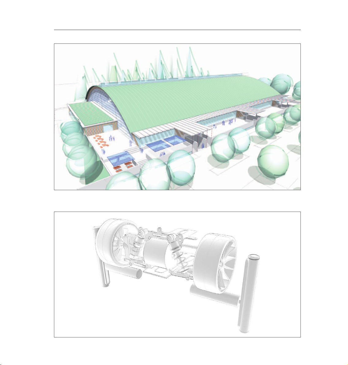
64 CINEMA 4D R13 Quickstart – Sample Images
© www.areyouplanning.de
© Johan-Bernd Zweverink
Page 69

65CINEMA 4D R13 Quickstart – Sketch and Toon
© Michail Stehle Design
4. Quick Tutorial – Shaders and Tags
In this tutorial we will combine an object rendered in the sketch mode with an object rendered in the normal
mode in the same scene. We will also examine the Cel shader, one of four special sketch shaders. Our goal
will be to assign different render styles to each of three objects. The first object will only have a contour and
it should look like it was hand-drawn. We will test the cel shader on the second object and give it cartoon-like
colors. The third object will look like a normal CINEMA 4D object rendered with standard settings.
Open the file, QS_SaT_Start.c4d.
Page 70

66 CINEMA 4D R13 Quickstart – Sketch and Toon
Create a new material in the Material Manager (Create / New Material). Deactivate the Color and Specular
channels in the Basic tab of the Attribute Manager. Activate Luminance and switch to the Luminance tab. Click
on the small arrow to the right of the word Texture. Select Sketch / Cel.
The cel shader is a type of gradient shader. It can be loaded into any channel but for a cartoon-like look it
should be put into the Luminance channel where its colors will always be rendered as full-tone and will not be
inuenced by the scene’s lighting.
Click on Cel. The cel settings will appear. 3 shades of blue are preset here by default but they don’t really
match our figures. Double click on the color sliders and create three colors with a green hue.
The number of colors represents the number of color steps an object will be colored with. 1-2 colors is always
good for a cartoon look. Drag the new material in the Object Manager onto Whimp_middle and render the
scene.
Page 71
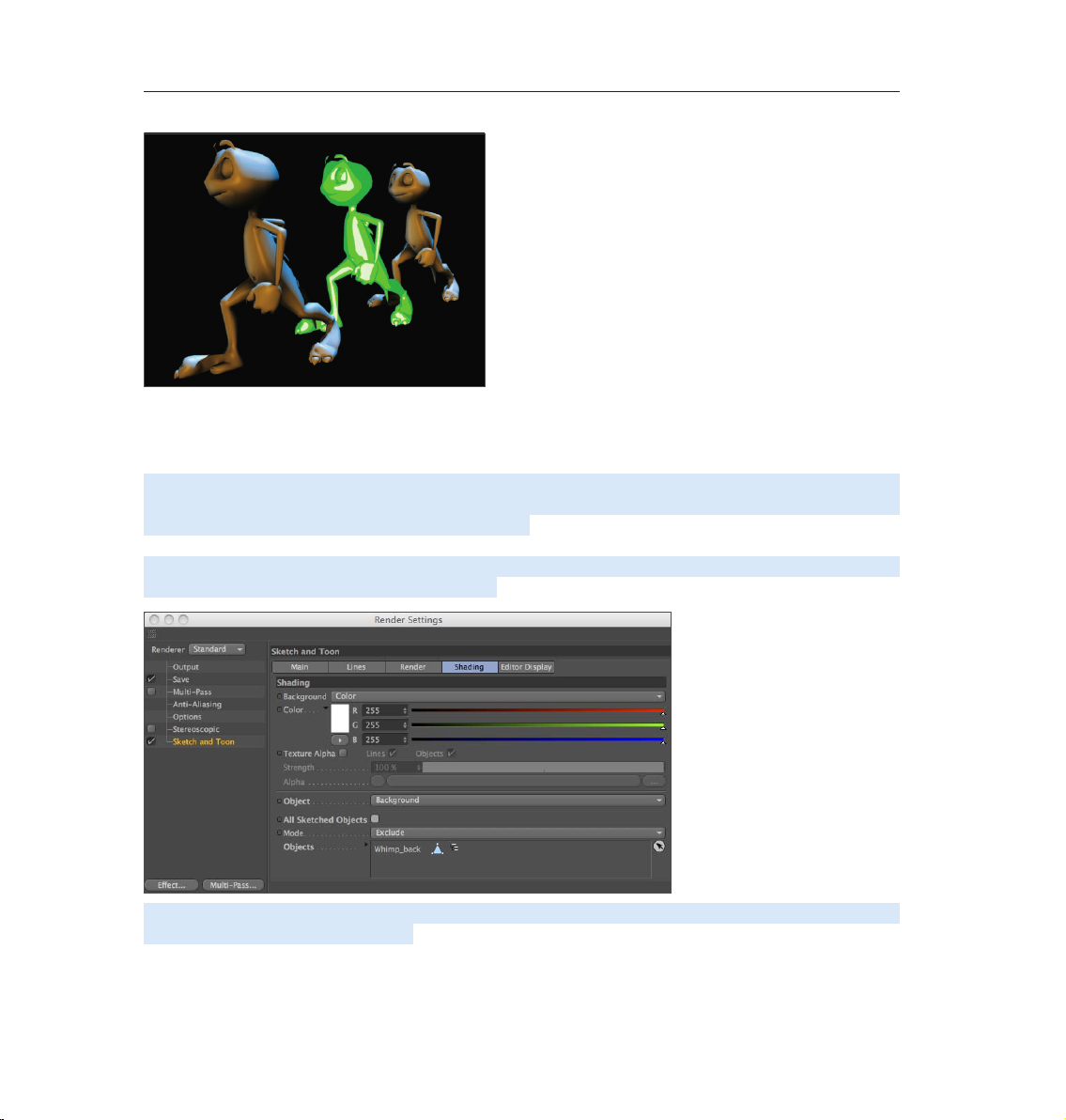
67CINEMA 4D R13 Quickstart – Sketch and Toon
Our Sketch and Toon figure is standing between two normal rendered figures. It is not necessary, though, to
activate the Sketch and Toon render effects in order to use a sketch shader. Now we will beautify the rear
figure with a contour.
Activate the Sketch and Toon effect in the Render Settings. Switch to the Shading tab and select Background
in the drop-down menu next to the word Object. Only the contour should be visible on the rear gure so we will
set its Inner Color to the same as the background color. If we were to render the scene now the other figures
would appear white as well so we will tell sketch that these settings should only apply to the rear puppet.
Deactivate the All Sketched Objects parameter. Select Include next to Mode and drag Whimp_back from the
Object Manager into the text eld under the menu. The shading settings will now only apply to this object.
Select the Sketch material that was just added and in the Attribute Manager’s Main tab, change Presets to
Pencil (Soft Sketch). Render the scene.
Page 72

68 CINEMA 4D R13 Quickstart – Sketch and Toon
Even though all figures have the correct filling each of the two front figures has assumed the contour style of
the figure behind it. We will deactivate the contour rendering for these two objects completely. Select Whimp_
front and Whimp_middle in the Object Manager and select Tags / Sketch Tags / Sketch Render. Deactivate
Allow Lines in the Attribute Manager.
We’ve done it! Three objects, each with completely different render styles coexisting peacefully in the same
scene.
Page 73

69CINEMA 4D R13 Quickstart – Sketch and Toon
5. Tips & Tricks
Sketch and Toon offers several levels of control. If you are taking your first
steps with this tool and are a little overwhelmed by the countless buttons and
sliders simply set the level of control to Easy (either in the Render Settings
or in the sketch material attributes). Several functions will then be hidden.
Once you feel more comfortable with Sketch and Toon (which shouldn’t take
too long after having completed this tutorial) you can move to the next level.
The time it takes to render a Sketch and Toon scene depends on the size and / or
complexity of your scene. If it takes too long, check for objects in the scene that can
excluded from the rendering process using tags. Lowering the anti-aliasing quality
(contour smoothing) can speed your rendering up as well. Make use of Sketch and
Toon’s exibility. You can assign different styles to visible and invisible lines,
just as you can assign a different style to individual objects in your scene.
The combination of standard rendering and Sketch and Toon can result in
especially spectacular images.
Use the countless presets, especially in the beginning, to give yourself a
good working knowledge of Sketch and Toon. If you nd a preset that you really like, examine it closely and see
what all it can do when you apply your own settings. This is the best way to find out how Sketch and Toon ticks.
Page 74

70 CINEMA 4D R13 Quickstart – Sample Images
© S. Scatola, www.boxy.co.uk
Page 75

71CINEMA 4D R13 Quickstart – Character Tools
© Takagi Leon
Character Tools
This is the Quickstart Tutorial for the CINEMA 4D character tools, a collection of tools especially for character
animation. CINEMA 4D includes a complete toolset for character animation. Many of these tools are available
in all packages and some are available only in CINEMA 4D Studio.
1. Introduction
3D character animation is a complex subject. It not only challenges the software but the animator as well.
Almost anyone can quickly create a character that moves in one way or another, but a convincing character
animation requires quite a bit more work. The animator needs to know the theory behind character animation
before he or she can judge whether or not the animation is good or bad.
Page 76

72 CINEMA 4D R13 Quickstart – Character Tools
So before we explore the character tools themselves we would like to quickly go over the 12 principles of
character animation. These 12 rules were developed back in the 1930s by Disney animators and can almost be
applied 1:1 to modern 3D animation. They are useful not only for characters but for just about anything you
animate. Anyone who is serious about character animation should stick these rules to the ceiling over their
bed (and get rid of whatever else that is up there now). A convincingly animated character will then be only a
matter of patience.
Squash & Stretch – every organic object deforms in some matter when it is in motion. Squash and
stretch is the exaggeration of this effect when a character is in motion.
Staging – is the setting up of an animation. This includes lighting, camera angle, effects and slow
motion.
Anticipation – Expectation of a reaction to an action is known as anticipation.
Pose to Pose / Straight Ahead – these terms describe two animation techniques. Pose to Pose sets
two important key poses and the time between is then filled. Straight Ahead sets one key after the
next – straight ahead through time.
Follow Through / Overlapping – the impetus or the overlapping of movement of a body parts.
Ease In / Ease Out – an object begins to move slowly, reaches its top speed and slowly comes to a halt.
Arcs – In nature almost every movement is described as arcs, no matter if it’s a swinging arm or the
rotation of a head.
Secondary Action – movement that is created by movement of another object.
Timing – the speed with which an action is executed.
Exaggeration – can be used in many instances: Arms that are being stretched too long when a
character is hanging from a cliff, eyes jumping out of their sockets to help demonstrate a shocked
expression.
Appeal – a character’s impression, look and nature.
Personality – like an actor, a good animator must be able to make his character express himself.
You can find more detailed descriptions of these rules online or in any good animation book. These rules might
seem pretty extensive at rst glance but the more you animate the more they will become your own esh and
blood. Every time your animation looks a little weird it will most likely be because you didn’t follow one or
more of these rules. Now we want to put these rules to use.
Page 77

73CINEMA 4D R13 Quickstart – Character Tools
2. General Information
First, we will explain a few basics about character rigging in CINEMA 4D. CINEMA 4D works with a Joint
system. Simply put, this system lets you assign joints and appropriate locations that will in turn be linked to
the mesh and used to rotate and move your character. The mesh will follow the joints to which it is linked and
the character can be animated. To be able to correctly move your character a rig consisting of controllers
must be set up that serve as handles for the animator. This way not every individual joint of an arm must be
moved in order to position the hand at the desired location - only a single controller has to be moved. There
are additional character controllers and helpers for character animation. A few of them are explained below.
The Morph tag lets you create various facial expressions for your characters and morph between them.
Your polygon object acts as the reference and a base morph (starting position for all following morphs) and
target morph are created in the Pose Morph tag. You select the morph target in the Morph tag and change
the mesh...finished!
You create another morph target for each additional pose and model the poses one after the other. All the
expressions are stored in a single tag. Also, when using the Pose Morph tool, there’s no need to worry if you
have to make changes to the mesh after creating the poses. The poses will still work! Suppose you’ve created
all the poses for your character, but decide it would look much better with a second nose. The Pose Morph tool
will still happily morph between the poses.
Vamp give s yo u the poss ibi lit y to tran sfer data from ob jec t to an oth er, in clu din g sel ection inform ation, Texture
tags, vertex maps and UVs. You can even transfer facial poses from one character to another!
Visual Selector is a great help with day-to-day animation. You load a render of your character into Visual
Selector‘s background (or use Visual Selector‘s default character picture) and place your character‘s
controllers onto the picture in the appropriate places. Visual Selector removes the need to keep looking for
your character‘s controls in the Object hierarchy. Everything is now represented visually and you can, for
example, select the foot controller by clicking on it directly in the picture. You want to move the eyes? No
problem. Click on the controller for the eyes directly in the picture.
You‘ll nd the CINEMA 4D character animation tools in the main menu under Character.
Since character animation is a complex subject matter, the following overview may help if you’re new to the
process of rigging characters.
As with a real human, your character needs a skeleton of bones (or in our case, joints) in order to be able to
move around in the world. You place the joints inside the character’s mesh. The joints are linked to the mesh
via a Weight tag and Skin deformer so that each joint knows which part of the geometry to affect.
Page 78

74 CINEMA 4D R13 Quickstart – Character Tools
You can weight joints by selecting them and painting directly onto the mesh using the Weight tool. While the
Weight tool is active, the mesh is displayed black and the currently painted weighting is shown in white. The
joint now knows it should affect the white painted parts of the mesh only. In the active Weight tool mode,
weighting is shown for the selected joints. Each joint has its own weighting.
The joints must be arranged into a hierarchy in the Object Manager in a similar structure to the bones in your
own body. In real life, when you move your upper arm, the lower arm and hand move with it because they are
effectively children of the upper arm.
Likewise, in CINEMA 4D’s Object Manager, the elbow and wrist joints must be children of the shoulder joint.
If you move the shoulder joint, the child joints will move with it together with the mesh weighted to the child
joints — even though the shoulder joint is weighted to the upper arm only.
As previously mentioned, each child joint has its own weighting and moves the parts of the mesh not weighted
to the shoulder joint.
Don’t worry if this seems complex. The following tutorials will explain all this in detail.
© Platinum, www.platinum.com.br
Page 79
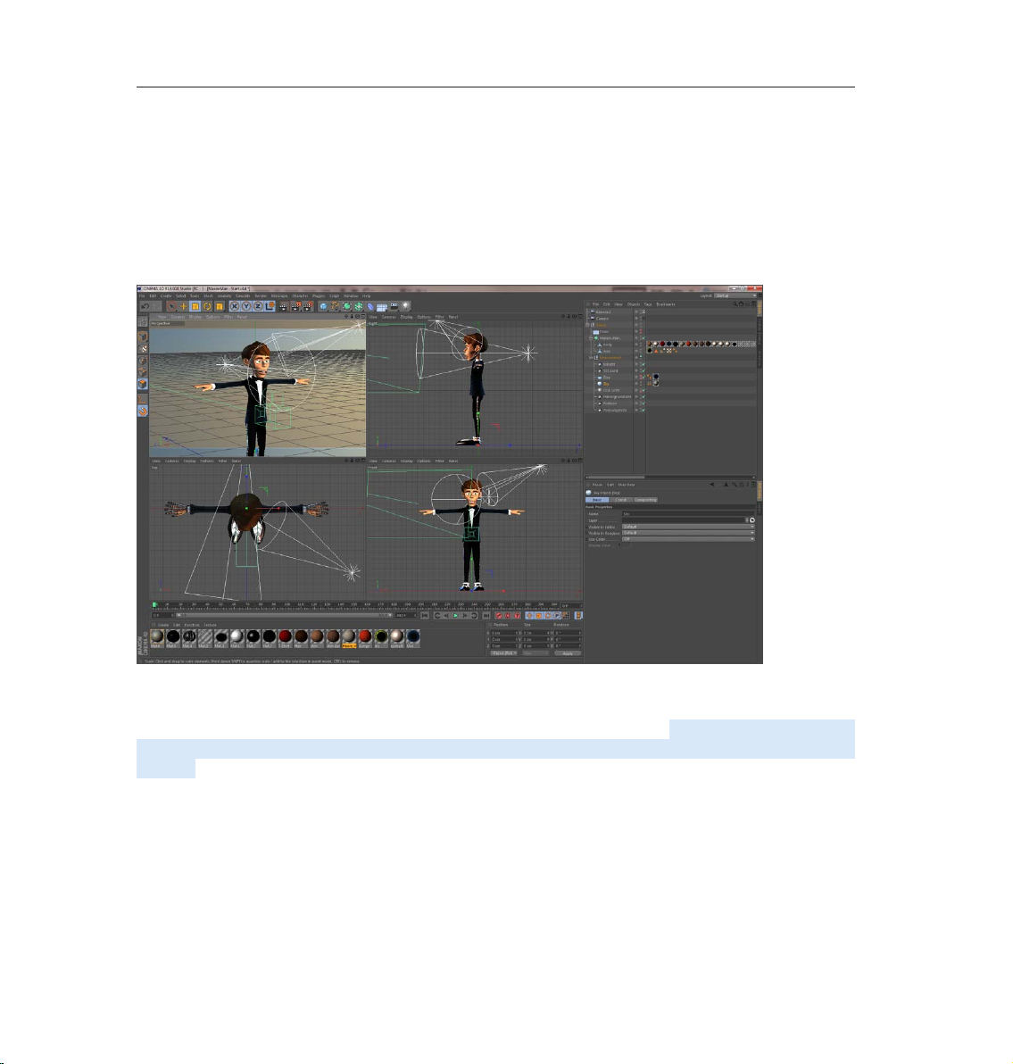
75CINEMA 4D R13 Quickstart – Auto Rigger and CMotion
3. Working with the Auto Rigger and CMotion
1. Creating the Basic Rig
Character rigging for 3D animation is one of the most complex and difcult disciplines in the eld of 3D
graphics. There is still no one-stop solution available but with CINEMA 4D R13, rigging and animating
characters is no longer a book with seven seals. Several new functions and tools have been added that make
working with characters much easier!
2. Preparation
Start CINEMA 4D and make sure you are using the Standard layout for the GUI. Open the scene, MaxonMan.
c4d, which contains the character mesh that we will rig in the course of this tutorial and animate using
CMotion. To make working with the character easier we should hide all other objects in the Project. To do so,
hide the Environment object in the Object Manager. Now only the character will be visible in the Project. It’s
also a good idea to set your Viewports up so you have a front, side and top view of your character in addition
to the perspective view. The Viewports have already been set up correctly for this tutorial so we can get
started more quickly.
Page 80

76 CINEMA 4D R13 Quickstart – Auto Rigger and CMotion
What we will do first is put the new character system in place. Select Character from the Character menu. A
symbol with the same name will appear in the Object Manager. The newly created object will appear as a gray
arrow in the Viewport.
In th e Attr i b ute Ma n ager yo u will se e th e Char a c ter ob j e c t ’s in i tia l se ttin g s . Numero u s para m e ter s are ava i labl e
here. When a Character object is created, its Object tab is active by default. This tab contains 4 menus: Build,
Adjust, Binding, Animate and represent the 4 steps required to complete an animatable character.
Directly below these tabs is the Template selection menu in which you can select the type of character rig you
want. You can select from Advanced Biped, Biped, Quadruped and many more. For this tutorial, select Biped.
This will let you create the rig for a humanoid biped. The rig that we will use in this tutorial is well-suited for
controlling (animating) a human character. More detailed rigs that offer much more complex control systems
can be created using the Advanced Biped rig. The Quadruped option, for example, makes it possible to create
a rig for four-legged creatures.
Selecting the Biped option hasn’t yet done much with regard to creating a rig. Directly below the Templates
options is the Components menu, which contains a Pelvis button. Clicking on the pelvis button will generate
a pelvis, which in turn will be used as the starting point for the entire rig. Once the pelvis has been created,
another button will appear – the Spine (Fk) button. Clicking on this button will create a spine that is connected
to the pelvis. Click on the arrow at the right and 2 options will be made available: FK (forward kinematics) and
IK (inverse kinematics). Select the IK option. Additional options will be made available, which let you create a
head, arms and legs.
Page 81
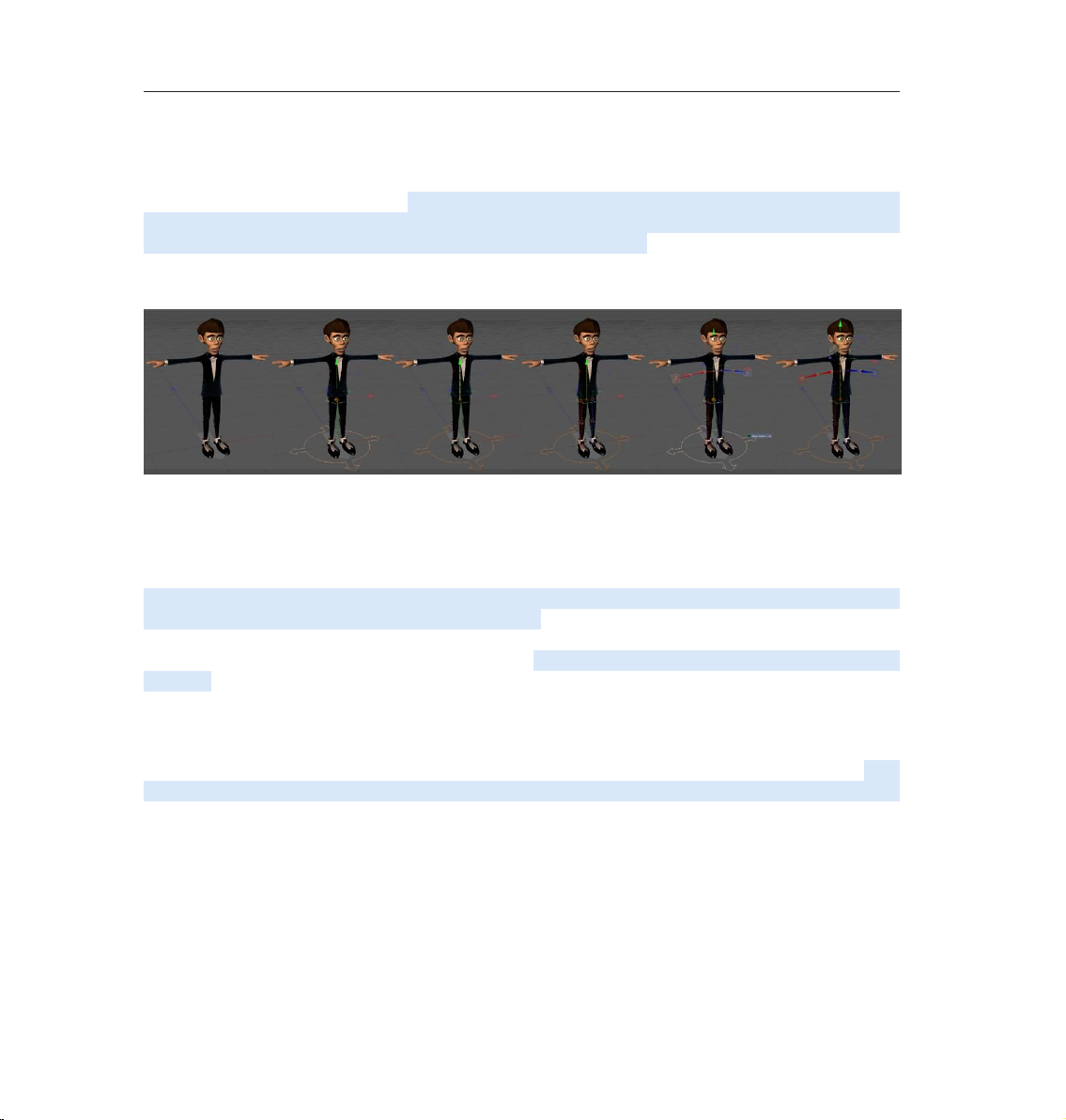
77CINEMA 4D R13 Quickstart – Auto Rigger and CMotion
Before we continue, lets take a look at our model in the perspective view. The parts of the rig that we have
created are not scaled in line with the character model. They are far too small. This is not a problem at this
stage because the adjustment and re-positioning of the rig’s individual components will be done later, after
all components have been generated. In the next step we will generate the legs. Here you can select between
Leg (foot) and Leg (IK). If you simply click on the button, a single leg will be generated. If you CMD/CTRL+click
on the button, two legs will be generated. Generate 2 legs with no toes. This is designed for characters that
wear shoes, which is the case with our character. If we had selected the Leg (foot) option, legs with feet and
five toes would have been generated.
Note that if buttons for further rig components are not displayed, check in the Object Manager to see which
component is currently selected. If, for example, you want to generate legs, the spine must be selected. If the
pelvis is selected, you will only be able to generate a spine. Alternatively you can SHIFT+click to remain in the
previous hierarchy.
Once the legs have been generated we will continue with the arms. Here you can also select between forward
and inverse kinematics, plus an additional option, Limb. While the former two options generate arms with
five fingers, the latter creates limbs with only upper and lower arm elements. To these you can later add
fingers, be it 2, 3, 4 or five – or however many you want. For this tutorial we will only use upper and lower arm
elements. Once you have added the arms, click on the Head button to add the head. This completes our rig.
3. Adjusting the Rig to Match the Mesh:
Let’s have a look at what we have done so far: We have created a rig that contains all components needed
for our character, only that the rig is too small. This is why we will now scale the rig to match our mesh. First,
select the Character object in the Object Manager and switch to the Adjust menu in the Attribute Manager.
The rig’s appearance will change drastically in the Viewport: it will turn into a green, red and blue stick gure
at whose joints are circles of the same color.
Page 82

78 CINEMA 4D R13 Quickstart – Auto Rigger and CMotion
First we will position the rig relative to the mesh. Select the Pelvis object in the Object Manager and use the
Move tool to move it upwards until is centered on the character’s pelvis. Don’t forget to check the position
in the side view to make sure the Pelvis object is centered there as well. Use the Scale tool to enlarge the rig
to match the mesh. Don’t worry if individual components are too short or too long – we will ne-tune these
as well. Once the rig roughly matches the mesh we can begin with the ne-tuning, which will be done using
the Move tool. Start with the legs by clicking on the joint at the top end of the upper leg and repositioning it
accordingly. CINEMA 4D automatically mirrors this adjustment on the other leg. Make sure to also check your
work in the side view.
A tip for positioning extremities: Arms, legs and ngers/toes (if present) are structured hierarchically. If, for
example, an upper leg is moved, the lower leg and foot will move accordingly. Therefore you should always
make sure to work from the inside out or downwards in the hierarchy.
Continue positioning the rig down to the feet and make sure the feet point slightly outward. This can be done
more easily from the top view.
We will now continue with the spine and the arms. The spine should not be placed towards the rear as in a real
body but rather near the center. Next, position the shoulders and arms accordingly.
Another tip: Joints such as knees and elbows deform the character significantly when animated. Therefore,
you must make sure that enough geometry is present at these locations in order to handle these deformations.
On our character you will see that the knee and elbow regions have three polygon rings. Place the rig’s
corresponding joints at the center of these rings so the bones will have an optimal influence on the mesh.
Furthermore, you should make sure that the knees and elbows have a very slight bend, as in reality. Polevectors
are used for these joints internally, which define the direction in which the joint will bend. By slightly bending
the knees and elbows, the final rig will be better adapted to the mesh.
Page 83

79CINEMA 4D R13 Quickstart – Auto Rigger and CMotion
Position the wrist next to the cufinks. Six joints are located because this is where the ngers will be
generated later. To locate the right joint, right-click on the wrist and select the right joint from the list that
appears (…Hand_con+). Now we just have to adjust the ngers and the head and our rig will be ready to be
bound to the character’s mesh.
4. Binding the Rig to the Character’s Mesh
Before you start binding the rig to the mesh it would certainly be a good idea to save your Project. After doing
so, make sure that the Character object is selected in the Object Manager, i.e. that the rig is selected. In the
Attribute Manager, switch to the Binding tab.
This will again change the appearance of the rig in the Viewport. It will again be made up of joints and bones.
Do uble- check the position of the bones and joints before getting star te d. Th e Bindi ng tab cont ai ns an inc lu sion
eld (Objects). Simply drag the polygon objects body and eyes from the Object Manager into this field. If you
need to place multiple objects into this field you can do so by either dragging each object individually or by
using the Object eld’s Start Pick Session function (click on the arrow in the white circle or right-click on
Object field).
Note: Do not place the HyperNURBS object into the Object eld.
This more-or-less completes the binding of the rig to the character’s mesh. However, before we move on to
the Animation menu where we will actually move our character, we still have to complete one more important
step. Don’t forget that the rig that we just bound to our character’s mesh is much more complex than it
looks. Numerous bones, Null objects and Controllers are needed in order to make the rig behave correctly
when animated. These have already been generated automatically by CINEMA 4D but are not visible. These
components are actually irrelevant for the person(s) creating the animation.
Page 84

80 CINEMA 4D R13 Quickstart – Auto Rigger and CMotion
Important for the animators are the Controllers. These Controllers represent virtual strings of a marionette
– which our character de-facto is. Hence, we only need these Controllers to be visible. Too many elements
in the Project would clutter up the view and slow your workflow. You can modify the visible state of the
rig’s components in the Attribute Manager’s Display tab. Select the Character object in the Object Manager
and switch to the Attribute Manager’s Display tab. Here you will nd several options for displaying the rig’s
components. The Viewport options affect the character’s rig in the Viewport and the Managers options dene
how the character’s rig is displayed in the Object Manager. First, select Controllers from the Manager menu’s
Object Manager setting. Now only these Controllers will be visible in the Object Manager, i.e. the objects that
are used to control the character.
5. Creating a Simple Walk Animation
We have now prepared our character so it can be animated. Select the Character object in the Object Manager
and switch to the Object tab’s Animate menu in the Attribute Manager. Click on the Add Walk button at the
right. This will assign a CMotion object to the Character object, which lets you generate cyclical animations or
movements such as a walk cycle. To do so, select the Character object’s CMotion object in the Object Manager
and take a look at its properties in the Attribute Manager’s Object tab.
Page 85

81CINEMA 4D R13 Quickstart – Auto Rigger and CMotion
Set the Stride value to 60cm. Now turn your attention to the list of objects in the Objects menu below and
select one of the legs (L_Leg or R_Leg) in the list. A set of parameters will be made available below. Below the
selected Leg in the list you will see the Lift (P.Y.) parameter. This is an Action that, as the name says, creates a
lifting motion so the corresponding foot rises during the walk motion. Try it out by clicking on the green Play
button (the green arrow just below the Viewport) and making your character walk in place.
Stop the animation and jump back to frame 0. Select the Lift parameter; its settings will be displayed below.
Increase the Lift value to 10cm and don’t forget to do the same for the other leg.
Alternatively you can right-click on the already modied parameter in the Object list and select Copy. Then
select and right-click on the other leg and select Paste. As you can see, you have now copied the lift action
from one leg to the other. If you play the animation again you will see that the character lifts its legs much
higher than before when it walks.
You will find another Lift action in the Object list, which lies below the Pelvis in the hierarchy. This controls the
rising and sinking motion of the pelvis during the walk cycle. You may have already noticed that this motion is
very sedated during the walk cycle. Set this parameter’s Lift (P.Y.) value to 3cm and play the animation again.
You should now have a more realistic pelvic movement. So far so good. Now we will continue with the arms,
which are still stretched out to the sides and of course don’t represent the natural position of a person’s arms
when walking. To repositi on the arms next to the torso, select an arm in the CMotion Attr ib ute Manager. Again ,
several parameters will be made available below, including Horiz and Vert. These values affect the orientation
of the selected arm or the Hand Goals of the respective arm to which the arm is oriented.
Set the left arm’s Vert value to -45cm and its Horiz value to 45cm; set the right arm’s Vert and Horiz values
each to -45cm. Now both arms lie slightly bent alongside the torso. Next, we want to make the arms swing
in tune with the walk cycle. So far we have only worked with Actions that were already included in the list.
Actions are an integral part of CMotion. A character’s movements are dened by the use of Actions and the
ne-tuning of their parameters. Select an arm from the Attribute Manager’s CMotion list and assign a Push
(P.Z.) parameter to it. To do so, select the arm, then the parameter from the drop-down list and then click on
the Add button next to the list. The Push (P.Z.) parameter will now appear in the list below the arm to which it
was assigned. Select the parameter and set its Push (P.Z.) value to 30cm. Right-Click on the graph below and
select Spline Presets / Sin from the context menu. This replaces the straight line with a sinus curve. Now you
can copy this Push (P.Z.) parameter to the other arm.
Page 86

82 CINEMA 4D R13 Quickstart – Auto Rigger and CMotion
6. The Finishing Touches
Play the animation again and observe how the arms swing back and forth. We have created a simple walk
cycle animation, which of course can still be ne-tuned quite a bit. You can, for example, make the character
actually walk past the camera instead of having it walk in place. To do so, all you have to do is set the Walk
parameter to Line or Path (which lets you move the character along a given Spline) in the CMotion’s Attribute
Manager’s Object menu.
You can also ne-tune the character’s gate, for example by modifying the Lift Action’s sinus curve. This curve
defines now far the feet rise and fall. Currently, the curve is smooth, which causes the feet to also rise and
fall smoothly. If you move the crest of the curve to the right near the end of the curve, the character will walk
with a more stomping motion.
You can also add Actions. For example, you can use the Curl Action on the arms with a moderate value,
which will curl the fingers. The higher the value, the more the hand will turn into a fist. You can also begin
modifying the character’s characteristics much earlier by ne-tuning the character’s weighting during the
binding process via the Weights Manager. You can ensure a more accurate deformation of geometry at the
joints by adding a Smoothing parameter, or you can add a Muscle parameter to make muscles bulge. All of the
available parameters and options can be used to ne-tune your character’s motion and characteristics until
you have an ultra-realistic animation.
Page 87

83CINEMA 4D R13 Quickstart – Pose Morph
4. Quick Tutorial – Pose Morph
The Pose Morph tool is a powerful tool for mixing Joints, points, UVs, parameters, User Data and much more
by morphing between states (e.g. size, position, rotation) using sliders. Using Pose Morph is as easily as it is
logical.
Open the le QS_Maxon_Head_start.c4d.
We will use Pose Morph to change the facial expression of our friend in the image above from friendly and
unassuming to consternated and silly.
Right-click on the Head object and select the Pose Morph tag from the Character Tags menu. Select the tag
in the Object Manager and activate the Points option in the Attribute Manager. An initial Pose (Base Pose)
will automatically be created. The Base Pose (displayed in the Poses list) is the state in which the points are
positioned at the moment the Pose Morph tag was applied. This list element should not be modified because
it represents the initial state for all subsequent morphs - all morph poses will reference this initial state.
Therefore, make sure this element is not selected (active) when modifying the object.
To start modifying the object, select the element Pose.0. Normally you would have to switch to the Point tool
but we have already taken care of this step for you.
At the right of the Head object in the Object Manager are three tags, each with four orange dots. Double-click
on the tag farthest to the left.
Page 88
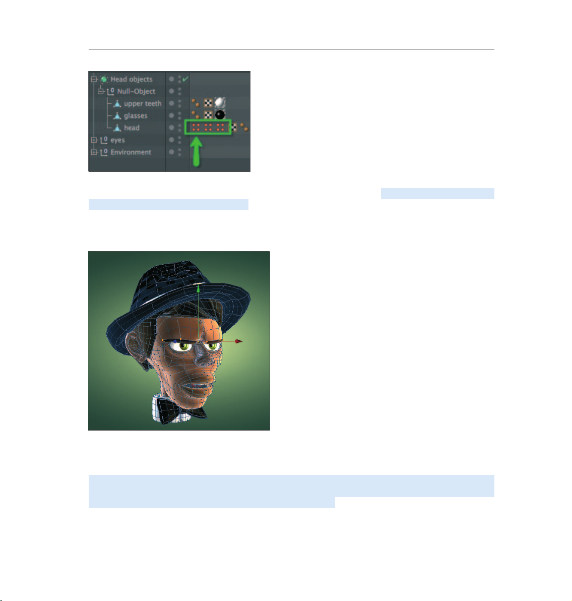
84 CINEMA 4D R13 Quickstart – Pose Morph
The pre-dened points will automatically be selected and CINEMA 4D will automatically be switched to Point
mode. In our example, the points that affect the eyebrows will be selected. Move these points downward,
slightly to the rear and rotate them slightly (To drag the eyebrows farther down for a “mean” look, the points
at the end of each eyebrow must be deselected and each eyebrow rotated separately. For our tutorial, however,
we can simply drag all points downwards simultaneoulsy.). If the eyeglasses get in the way, simply turn off
their display in the Object Manager. When finished, your object should look like the one below:
Tip: The axis orients itself according to all selected points as a whole, which can lead to unwanted rotations.
Hence, it is sometimes easier to use the World axis when rotating selected points. To do so, select the desired
function (Move, Scale, Rotate) and set Axis to World in the Attribute Manager’s Modeling Axis tab.
With the Pose Morph tag selected, click on the Add Pose button in the Attribute Manager to define additional
poses for the mouth and tongue, for example (these points are also pre-dened in the Object Manager).
Simply double-click on the respective icon (with four orange dots).
Page 89

85CINEMA 4D R13 Quickstart – Pose Morph
On ce all pose s have been de ned we ca n beg in mixing the poses. In the Attri bute Mana ger, set the Mode option
from Edit to Animate (Tag tab). The Pose Morph tag’s options will change automatically and you can dene
the strength with which the poses will be mixed using the Strength value. All morph targets are animatable.
Page 90

86 CINEMA 4D R13 Quickstart – Pose Morph
5. Tips and Tricks
• To create Joint poses with Pose Morph all you have to do is add a Pose Morph tag to the top-most Joint and
enable the Rotation and Hierarchy options. You can then rotate the Pose Target’s Joints without modifying
the Joints’ original position.
• The joints of the ngers of a hand only need a single Pose Morph tag with an enabled Hierarchy option.
Simply create a new Pose for each finger pose. This lets you keep the Object Manager more organized because
all Poses for a single hand will handled by a single Pose Morph tag.
• You can use the Driver tag to control Poses automatically. Assign the Driver tag to the Joint and link a Pose
directly to a specic rotational direction of the Joint. This can, for example, be used to simulate the exing of
muscles when an arm is bent.
• If you want to use a specic Pose as an initial state you can right-click on the desired Pose and copy & paste
it accordingly.
• If you want to convert a Pose into a polygon object outside of the Pose Morph tag, right-click on each Pose
and select the To Mesh command.
• Make sure not to disable options previously enabled in the Pose Morph tag’s Basic tab (e.g. Points, Rotation,
etc.). This will delete all defined Pose Morph Targets. Enabling these options again will not restore these
Targets.
• To avoid accidentally modifying the initial pose, right-click on the Pose, select the Lock command from the
menu. Alternatively you can click on the lock icon next to the element in the list.
Page 91

87CINEMA 4D R13 Quickstart – Sample Images
© Jana Rot, www.rot.si
Page 92

88 CINEMA 4D R13 Quickstart – Cloth
6. Quick Tutorial – Cloth
CINEMA 4D contains a very powerful Cloth engine. You can use this tool to let a flag flap in the breeze or to
give your character a snappy T-shirt. This is exactly what we want to put on Claude.
What’s nice about the Cloth engine is that it’s not ne cess ary to go through the trouble of mode li ng a T-sh ir t. All
you have to do is create the front and the back of the shirt. The integrated algorithms will make the garment
fit automatically.
Open the file QS_Cloth_Start.c4d. This le already contains both T-shirt halves as a single object.
If you don’t like the shirt feel free to replace it with your own creation. As you can see it was created with very
few polygons. The simplest method of closing the edges of the T-shirt is to switch to the Use Polygon tool and
select all of the shirt’s polygons (Cmd / Ctrl + a in the Viewport). Then activate the Bridge tool and disable the
Delete Original Polygons option in the Attribute Manager. Now click on one of the rear polygons, whose edges
will then be highlighted. Keep the mouse button pressed and drag the edges towards the front polygons,
whose edges will then also be highlights.
Once the mouse button is released, all the polygons necessary for connecting the halves will be created. Just
make sure that the corners are connected correctly. Otherwise the polygons will be connected incorrectly.
You can now delete the superuous polygons (neck opening, sleeves, waist).
Page 93
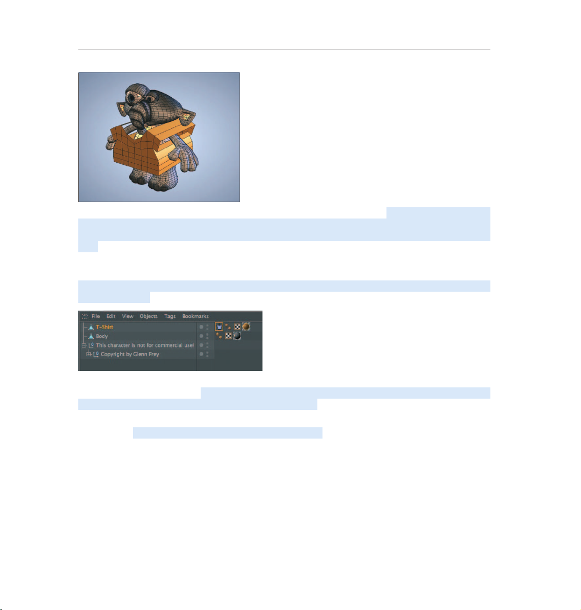
89CINEMA 4D R13 Quickstart – Cloth
The shirt needs to be subdivided a little more so you can deform it better later. Switch to Use Polygon Tool
mode and select the polygons on the front and back side of the shirt. Select Mesh / Commands / Subdivide
from the main menu. Make sure you don’t subdivide the polygons on the side (the ones created by the bridge
tool). OK, it doesn’t really look like a T-shirt yet, it looks more like a box with sleeves. But don’t worry, we’re
going to change that right now. The Cloth engine is very easy to use. Most functions are contained in one tag,
the Cloth Tag. It will be assigned to the object, which will then be turned to cloth!
Right-click on the shirt and select Simulation Tags / Cloth. The Cloth engine’s properties will appear in the
Attribute Manager.
If the cloth object is to collide with another objec t, as is the case with the T-shi rt and the body, the other object
must be assigned a collision tag. Select the character’s body (polygon obj ec t Body) in the Object Manag er with
the right mouse button. Select Simulation Tags / Cloth Collider.
Now the T-shirt knows that is should not pass through the character. It’s about time that we gave the shirt its
proper shape. Select the cloth tag and switch to the Dresser tab.
Page 94

90 CINEMA 4D R13 Quickstart – Cloth
In the dresser tab you will nd everything you need to make clothes t. The other tabs deal with the cloth’s
behavior. Select Set next to Dress State. This is like a security measure. We can recall the shirt’s initial state
in case we don’t like the position of the shirt or if we want to add a breast pocket, for example. Switch to Use
Polygon Tool mode and select the polygons on the sides (the ones created by the bridge tool). Alternatively
you can select Select / Invert in the Selection in the CINEMA 4D main menu - since the front a back side of the
shirt should still have been selected, this can save you time.
These polygons will serve as the T-shirt’s seam. The Cloth engine will do this for us as well. Select Seam Polys
in the Dresser menu and set it to Set. The seam is still a little too wide. Click on Dress-O-Matic and look what
happens with the T-shirt.
Page 95
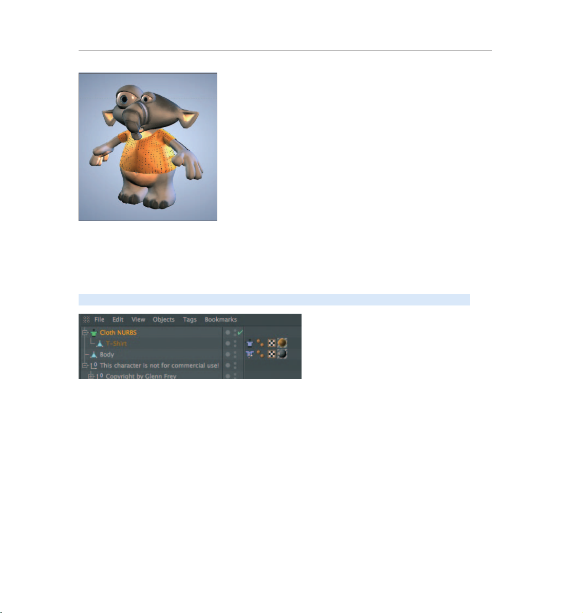
91CINEMA 4D R13 Quickstart – Cloth
The seam will be pulled together in accordance to the Width value. It doesn’t necessarily match the shape
of the character’s body, though. The Steps value determines how exact this t will be. After setting the Init.
State, click on Relax.
Now other forces, such as gravity, will have an effect on the T-shirt which makes it sag on the character’s
shoulders.
Place a Cloth NURBS into the scene (Simulate / Cloth / CNURBS). Make the T-shirt a child of this object.
Cloth NURBS acts similar to a HyperNURBS object: it smooths the geometry which was subordinated to it
but with a slightly different algorithm which works better for cloth objects. Additionally, a thickness can be
specified for Cloth NURBS fabric objects.
Page 96

92 CINEMA 4D R13 Quickstart – Cloth
Set the Thickness to 1 or 2 in the Attribute Manager and the subdivision to 0. Create a HyperNURBS object
and make the Cloth NURBS object to a Child object of this HyperNURBS object. Now the Cloth NURBS object
will concentrate on the thickness of the cloth and the HyperNURBS object will take care of the T-shirt’s edges.
The character should be clothed now. Of course there is still some ne-tuning necessary to make the T-shirt
behave properly in an animation. As you can see, though, the rst steps weren’t that difcult.
Page 97

© S. Scatola, www.boxy.co.uk
93CINEMA 4D R13 Quickstart – Sample Images
© Beto Prado - www.animalda.com.br
Page 98

94 CINEMA 4D R13 Quickstart – HAIR
© Marcelo Biscola - www.artnetdigital.com.br
HAIR
CINEMA 4D Studio features a hair rendering and simulation system that you can use to easily create hair, fur
and feathers. This tutorial will show you how.
1. Introduction
HAIR is a powerful tool for creating various types of hair and fur. Even feathers, animated grass, and much
more can be created using HAIR.
Althou g h ac h i e v i n g yo ur r s t re s u l t s in HAIR is relatively easy, HAIR is an im m e n s e l y di ver s e an d co m p reh e n s i v e
tool that will satisfy any beautician.
HAIR can be accessed from the Simulate menu at the top of your standard interface.
Page 99

95CINEMA 4D R13 Quickstart – HAIR
HAIR’s only limitation is your fantasy, whether it’s creating fur for a rodent, feathers for a rufed chicken,
the perfect English lawn or the newest hairstyles. And, HAIR is fast – what else have you come to expect from
CINEMA 4D? HAIR renders immense amounts of hair with unmatched speed. The variations that HAIR offers
are so great that any hairstyle can be created, from smooth and straight to curly or just about anything you
can imagine.
2. General Information / Interface
HAIR works with so-called guides that serve as placeholders for the rendered hair.
The number of guides displayed in the editor view is far less than the actual number of hairs that will be
rendered. The number of guides displayed can also be increased. The missing hairs are interpolated between
the guides when rendered. Naturally, you will require some standard grooming tools to bring your hair into
shape. Among the tools HAIR offers are Brush, Comb, Scissors and more.
Page 100

96 CINEMA 4D R13 Quickstart – HAIR
HAIR’s own IK makes sure hair moves realistically. Even some of the CINEMA 4D particle modiers, e.g.
wind, can be combined with HAIR and the HAIR dynamics ensure hair behaves naturally. And if you want to
transplant hair, that’s no problem, either. HAIR lets you easily transplant hair roots.
Before we get sta rted with the HAIR tutorial, thoug h, let’s take a lo ok at what can be create d wi th CIN EM A 4D ’s
HAIR system:
 Loading...