

Page 1
Quickstart Manual
3D FOR THE REAL WORLD
CINEMA 4D
RELEASE 10
Page 2

CINEMA 4D Release 10
Quickstart Manual
ICINEMA 4D R10 Quickstart
Programming Christian Losch, Philip Losch, Richard Kurz, Tilo Kühn, Thomas Kunert, David O’Reilly,
Plugin programming Sven Behne, Wilfried Behne, Michael Breitzke, Kiril Dinev, Reinhard Hintzenstern,
Produc t Manager Marco Tillmann
Writers Glenn Frey, Sven Hauth, Dirk Beichert, Fabian Rosenkranz
Layout Oliver Becker, Oliver Krawc zyk
Translation Scot Wardlaw, Luke Stacy
Copyright © 1989 - 2006 by MAXON Computer GmbH All rights reserved.
This manual and the accompanying software are copyright protected. No part of this document may be translated, reproduced,
stored in a retrieval system or transmitted in any form or by any means, electronic or mechanical, for any purpose, without
the express written permission of MA XON Computer.
Although every precaution has been taken in the preparation of the program and this manual, MAXON Computer assumes
no responsibilit y for errors or omissions. Neither is any liability assumed for damages resulting from the use of the program
or from the information contained in this manual.
This manual, as well as the software described in it, is furnished under license and may be used or copied only in accordance
with the terms of such license. The content of this manual is furnished for informational use only, is subject to change without
notice, and should not be construed as a commitment by MAXON Computer. MA XON Computer assumes no responsibility
or liability for any errors or inaccuracies that may appear in this book.
MAXON Computer, the MAXON logo, Sketch and Toon, CINEMA 4D, Hyper NURBS, C .O.F.F.E.E. are trademarks of MAXON
Computer GmbH or MA XON Computer Inc. Acrobat, the Acrobat logo, PostScript, Acrobat Reader, Photoshop and Illustrator
are trademarks of Adobe Systems Incorporated registered in the U.S. and other countries. Apple, AppleScript, AppleTalk,
ColorSync, Mac OS, QuickTime, Macintosh and TrueType are trademarks of Apple Computer, Inc. registered in the U.S. and
other countries. QuickTime and the QuickTime logo are trademarks used under license. Microsof t, Windows, and Windows
NT are either registered trademarks or trademarks of Microsoft Corporation in the U.S. and /or other countries. LightWave is
a registered trademark of NewTek. 3D studio max and 3ds max are registered trademarks of Autodesk /Discreet Inc. UNIX is
a registered trademark only licensed to X/Open Company Ltd. All other brand and product names mentioned in this manual
are trademarks or registered trademark s of their respec tive companies, and are hereby acknowledged.
Cathle en Poppe, Per-Anders Edwards, Paul Everett
Eduardo Olivares, Nina Ivanova, Markus Jakubietz, Hendrik Stef fen, Jens Uhlig,
Michael Welter, Thomas Zeier
Page 3

II CINEMA 4D R10 Quickstart
MAXON Computer End User License Agreement
NOTICE TO USER
WITH THE INSTALL ATION OF CINEMA 4D AND ALL ITS COMPONENTS AND PLUGINS (THE “SOFTWARE”) A
CONTR ACT IS CONCLUDED BET WEEN YOU (“YOU” OR THE “USER”) AND MAXON COMPUTER GMBH ( THE
“LICENSOR”), A COMPANY UNDER GERMAN LAW WITH RESIDENCE IN FRIEDRICHSDORF, GERMANY.
WHEREAS BY USING AND/OR INSTALLING THE SOFTWARE YOU ACCEPT ALL THE TERMS AND CONDITIONS OF
THIS AGREEMENT. IN THE CASE OF NON-ACCEPTANCE OF THIS LICENSE YOU ARE NOT PERMITTED TO INSTALL
THE SOFTWARE.
IF YOU DO NOT ACCEPT THIS LICENSE PLEASE SEND THE SOFTWARE TOGETHER WITH ACCOMPANYING
DOCUMENTATION TO MAXON COMPUTER OR TO THE SUPPLIER WHERE YOU BOUGHT THE SOFTWARE.
1. General
Under this contract the Licensor grants to you, the User, a non-exclusive license to use the Software and its associated
documentation. The Software itself, as well as the copy of the Software or any other copy you are authorized to make
under this license, remain the proper ty of the Licensor.
2. Use of the Software
(1) You are authorized to copy the Software as far as the copy is necessary to use the Software. Necessary copies are the
installation of the program from the original disk to the mass storage medium of your hardware as well as the loading of
the program into RAM.
(2) Furthermore the User is entitled to make a backup copy. However only one backup copy may be made and kept. This
backup copy must be identified as a backup copy of the licensed Software.
(3) Further copies are not permitted; this also includes the making of a hard copy of the program code on a printer as well
as copies, in any form, of the documentation.
3. Multiple use and network operation
(1) You may use the Software on any single hardware platform, Macintosh or Windows, and must decide on the platform
(Macintosh or Windows operating system) at the time of installation of the Sof tware. If you change the hardware you
are obliged to delete the Sof tware from the mass storage medium of the hardware used up to then. A simultaneous
installation or use on more than one hardware system is not permitted.
(2) The use of the licensed Software for network operation or other client server systems is prohibited if this opens the
possibility of simultaneous multiple use of the Software. In the case that you intend to use the Software within a network
or other client server system you should ensure that multiple use is not possible by employing the necessary access
security. Otherwise you will be required to pay to the Licensor a special network license fee, the amount of which is
determined by the number of Users admitted to the network.
(3) The license fee for network operation of the Software will be communicated to you by the Licensor immediately after
you have indicated the number of admitte d users in writing. The correct address of the Licensor is given in the manual
and also at the end of this contract. The network use may star t only af ter the relevant license fee is completely paid.
Page 4

IIICINEMA 4D R10 Quickstart
4. Transfer
(1) You may not rent, lease, sublicense or lend the Sof tware or documentation. You may, however, transfer all your rights
to use the Software to another person or legal entity provided that you transfer this agreement, the Software, including
all copies, updates or prior versions as well as all documentation to such person or entit y and that you retain no copies,
including copies stored on a computer and that the other person agrees that the terms of this agreement remain valid and
that his acceptance is communicated to the Licensor.
(2) You are obliged to carefully store the terms of the agreement. Prior to the transfer of the Software you should inform
the new user of these terms. In the case that the new user does not have the terms at hand at the time of the transfer of
the Software, he is obliged to request a second copy from the Licensor, the cost of which is born by the new licensee.
(3) After transfer of this license to another user you no longer have a license to use the Software.
5. Updates
If the Sof tware is an update to a previous version of the Software, you must possess a valid licence to such previous
version in order to use the update. You may continue to use the previous version of the Soft ware only to help the
transition to and the installation of the update. After 90 days from the receipt of the update your licence for the previous
version of the Sof tware expires and you are no longer permitted to use the previous version of the Sof tware, except as
necessary to install the update.
6. Recompilation and changes of the Software
(1) The recompilation of the provided program code into other code forms as well as all other types of reverse engine ering
of the different phases of Software production including any alterations of the Sof tware are stric tly not allowed.
(2) The removal of the securit y against copy or similar safety system is only permitted if a faultless performance of the
Software is impaired or hindered by such security. The burden of proof for the fact that the performance of the program
is impaired or hindered by the security device rests with the User.
(3) Copyright notices, serial numbers or other identifications of the Software may not be removed or changed. The
Software is owned by the Licensor and its structure, organization and code are the valuable trade secrets of the Licensor.
It is also protected by United States Copyright and International Treat y provisions. Except as stated above, this agreement
does not grant you any intellec tual propert y rights on the Software.
7. Limited warranty
(1) The parties to this agreement hereby agree that at present it is not possible to develop and produce software
in such a way that it is fit for any conditions of use without problems. The Licensor warrants that the Software will
perform subst antially in accordance with the documentation. The Licensor does not warrant that the Sof tware and the
documentation comply with certain requirement s and purposes of the User or works together with other sof tware used
by the licensee. You are obliged to check the Software and the documentation carefully immediately upon receipt and
inform the Licensor in writing of apparent defects 14 days after receipt. Latent defects have to be communicated in
the same manner immediately after their discovery. Otherwise the Sof tware and documentation are considered to be
faultless. The defects, in particular the symptoms that occurred, are to be described in detail in as much as you are able to
do so. The warranty is granted for a period of 6 months from delivery of the Software (for the date of which the date of
the purchase according to the invoice is decisive). The Licensor is fre e to cure the defects by free repair or provision of a
faultless update.
Page 5

IV CINEMA 4D R10 Quickstart
(2) The Licensor and its suppliers do not and cannot warrant the performance and the results you may obtain by using
the Software or documentation. The foregoing states the sole and exclusive remedies for the Licensor’s or it s suppliers’
breach of warranty, except for the foregoing limited warranty. The Licensor and its suppliers make no warranties, express
or implie d, as to noninfringement of third part y rights, merchantability, or fitness for any par ticular purpose. In no event
will the Licensor or its suppliers be liable for any consequential, incidental or special damages, including any lost profits or
lost savings, even if a representative of the Licensor has been advised of the possibility of such damages or for any claim
by any third party.
(3) Some states or jurisdictions do not allow the exclusion or limitation of incidental, consequential or special damages, or
the exclusion of implied warranties or limitations on how long an implied warrant y may last, so the above limitations may
not apply to you. In this case a special limited warranty is attached as exhibit to this agreement, which becomes par t of
this agre ement. To the extent permissible, any implied warranties are limited to 6 months. This warranty gives you specific
legal rights. You may have other rights which vary from state to state or jurisdiction to jurisdiction. In the case that no
special warrant y is attached to your contract please contact the Licensor for further warranty information.
8. Damage in transit
You are obliged to immediately inform the transport agent in writing of any eventual damages in transit and you should
provide the Licensor with a copy of said correspondence, since all transportation is insured by the Licensor if shipment
was procured by him.
9. Secrecy
You are obliged to take careful measures to protect the Software and its documentation, in particular the serial number,
from access by third parties. You are not permitted to duplicate or pass on the Software or documentation. These
obligations apply equally to your employees or other persons engaged by you to operate the programs. You must pass on
these obligations to such per sons. You are liable for damages in all instances where these obligations have not been met.
These obligations apply equally to your employees or other persons he entrusts to use the Software. The User will pass
on these obligations to such persons. You are liable to pay the Licensor all damages arising from failure to abide by these
terms.
10. Information
In case of transfer of the Soft ware you are obliged to inform the Licensor of the name and full address of the transferee in
writing. The address of the Licensor is stated in the manual and at the end of this contract.
11. Data Protection
For the purpose of customer registration and control of proper use of the programs the Licensor will store personal data
of the Users in accordance with the German law on Data Protection (Bundesdatenschutzgeset z). This data may only be
used for the above-mentioned purposes and will not be accessible to third parties. Upon request of the User the Licensor
will at any time inform the User of the data stored with regard to him.
12. Other
(1) This contrac t includes all rights and obligations of the parties. There are no other agreements. Any changes or
alterations of this agreement have to be performed in writing with reference to this agreement and have to be signed by
both contracting parties. This also applies to the agre ement on abolition of the written form.
Page 6

(2) This agreement is governed by German law. Place of jurisdic tion is the competent court in Frankfurt am Main. This
agreement will not be governed by the United Nations Convention on Contracts for the International Sale of Goods, the
application of which is expressly excluded.
(3) If any part of this agreement is found void and unenforceable, it will not affect the validity of the balance of the
agreement which shall remain valid and enforceable according to its terms.
13. Termination
This agreement shall automatically terminate upon failure by you to comply with its terms despite being given an additional
period to do so. In case of termination due to the aforementioned reason, you are obliged to return the program and all
documentation to the Licensor. Furthermore, upon request of Licensor you must submit written declaration that you are not in
possession of any copy of the Software on data storage devices or on the computer itself.
14. Information and Notices
Should you have any questions concerning this agreement or if you desire to contac t MAXON Computer for any reason
and for all notifications to be performed under this agreement, please write to:
MAXON Computer GmbH
Max-Planck-Str. 20
D-61381, Friedrichsdor f
Germany
or for Nor th and South America to:
MAXON Computer, Inc.
2640 Lavery Court Suite A
Newbury Park, CA 91320
USA
or for the United Kingdom and Republic of Ireland to:
MAXON Computer Ltd
The Old School, Greenfield
Bedford MK45 5DE
United K ingdom
We will also be pleased to provide you with the address of your nearest supplier.
VCINEMA 4D R10 Quickstart
Page 7

VI CINEMA 4D R10 Quickstart
Contents
MAXON Computer End User License Agreement .................................................................... II
Welcome to CINEMA 4D ..................................................................... 2
2. General Information / Interface ........................................................................................ 3
3. Sample Images ............................................................................................................... 12
4. Quick Tutorial – Arranging Objects ................................................................................. 14
5. Quick Tutorial – Modeling ............................................................................................... 21
6. Quick Tutorial – Materials ............................................................................................... 28
7. Quick Tutorial – Light ...................................................................................................... 37
8. Quick Tutorial – Animation ............................................................................................. 43
9. Quick Tutorial – Rendering .............................................................................................. 50
10. Quick Tutorial – Multi-Pass Rendering ........................................................................... 57
11. Quick Tutorial – XPresso .............................................................................................. 63
Welcome to BodyPaint 3D ................................................................ 70
1. Introduction ................................................................................................................... 70
2. General Information / Interface ...................................................................................... 71
3. Sample Images .............................................................................................................. 73
4. Quick Tutorial – the Wizard ............................................................................................ 74
5. Quick Tutorial – First Painting Lesson .............................................................................. 76
6. Tips and Tricks ................................................................................................................80
Welcome to Advanced Render ......................................................... 82
2. General Information / Interface ...................................................................................... 83
3. Sample Images ............................................................................................................... 85
4. Quick Tutorial – Global Illumination ................................................................................ 87
5. Quick Tutorial – Caustics ................................................................................................. 90
6. Quick Tutorial – Depth of Field ....................................................................................... 92
7. Tips and Tricks ................................................................................................................94
Welcome to PyroCluster ................................................................... 95
1. Introduction ................................................................................................................... 95
2. General Information / Interface ...................................................................................... 95
3. Sample Images ............................................................................................................... 97
4. Quick Tutorial – 10 Steps to Glory .................................................................................. 98
5. Quick Tutorial – optimize and animate ......................................................................... 101
6. Tips & Tricks .................................................................................................................. 104
7. In Closing .....................................................................................................................104
Welcome to Sketch and Toon ......................................................... 107
1. Introduction ................................................................................................................. 107
2. General Information / Interface .................................................................................... 107
Page 8

VIICINEMA 4D R10 Quickstart
3. Sample Images ............................................................................................................. 110
5. Quick Tutorial – Shaders and Tags ................................................................................. 114
6. Tips & Tricks .................................................................................................................. 118
Welcome to NET Render ................................................................. 121
1. Introduction ................................................................................................................. 121
2. General Information / Interface .................................................................................... 121
3. Sample Images ............................................................................................................. 122
4. Quick Tutorial – Installation / Interface ......................................................................... 123
5. Quick Tutorial – Jobs and Administration ..................................................................... 124
6. Tips & Tricks .................................................................................................................. 125
Welcome to Dynamics .................................................................... 126
1. Introduction ................................................................................................................. 127
2. General Information / Interface .................................................................................... 127
3. Sample Images ............................................................................................................. 128
4. Quick Tutorial – Rigid Bodies ........................................................................................ 129
5. Quick Tutorial – Soft Bodies .......................................................................................... 131
6. Tips and Tricks ..............................................................................................................133
Welcome to Thinking Particles ....................................................... 134
1. Introduction ................................................................................................................. 134
2. General Information / Interface .................................................................................... 135
3. Quick Tutorial – Particle Snow ....................................................................................... 137
4. Quick Tutorial – Objects as Particles .............................................................................. 140
5. Tips & Tricks .................................................................................................................. 145
6. In Closing .....................................................................................................................145
Welcome to MOCCA ....................................................................... 146
1. Introduction ................................................................................................................. 147
2. General Information/Interface (Joints and Rigging) ...................................................... 148
3. Quick Tutorial – Forward Kinematics/Inverse Kinematics (FK/IK) .................................... 153
4. Quick Tutorial – Visual Selector ..................................................................................... 155
5. Quick Tutorial – PoseMixer ............................................................................................ 158
6. Quick Tutorial – Morph Tool .......................................................................................... 160
7. Quick Tutorial – Muscles ............................................................................................... 162
8. Quick Tutorial – Vamp .................................................................................................. 165
9. Quick Tutorial – Dressing .............................................................................................. 168
10. Quick Tutorial – FBX Import / Export ........................................................................... 171
Welcome to HAIR ............................................................................ 174
1. Introduction ................................................................................................................. 174
2. General / Interface ........................................................................................................ 174
3. Sample Images ............................................................................................................. 176
4. Quick Tutorial – Fur ....................................................................................................... 177
Page 9

VIII CINEMA 4D R10 Quickstart
5. Tips & Tricks .................................................................................................................. 187
Welcome to MoGraph .................................................................... 188
1. Introduction ................................................................................................................. 188
2. General / Interface ........................................................................................................ 189
4. Quickstart Tutorial ........................................................................................................ 192
5. Tips & Tricks .................................................................................................................. 197
Page 10

© Chen Shih Wei - Sunglow Design Studio
Page 11

2 CINEMA 4D R10 Quickstart – Interface
Welcome to CINEMA 4D
This is the CINEMA 4D Quickstart Tutorial. We want to help you enter the 3D world with this short and easy to
understand tutorial. After you have worked through this tutorial you will have a good basic user knowledge
which you can apply to future projects.
© Dave Brinda - www.brinda.com
1. Introduction
Unfortunately books haven’t yet reached the point where they can play an opening melody as soon as you flip them
open. Just use your imagination this time as we “congratulate you to the testing of the demo version of CINEMA 4D or
the purchase of CINEMA 4D!“ No matter if you’re just checking CINEMA 4D out or if you already own your own copy
of CINEMA 4D or one of its complete XL or Studio Bundle packages, you already know about the incredible things
CINEMA 4D can do. We have been working very closely with our customers for several years now in order to
satisfy their needs and wishes. This has lead to the creation and introduction of new functionality, according
to their needs. These ideas and concepts are then creatively implemented to satisfy the needs of our customers
and those of the 3D markets. No matter if you work in the field of print, advertising, design, visualization or
film, CINEMA 4D gives you all the tools you need to make your ideas reality. The intuitive interface and the
ease with which CINEMA 4D can be learned makes entering the versatile world for 3D a snap. Whether you
need character animation (MOCCA module) or a car toony look of your renderings (Sketch and Toon module)
– CINEMA 4D’s modular setup lets you customize it to suit your needs. CINEMA 4D places a link between your
job or hobby, and your creativity in the palm of your hand. You can create what your fantasy demands. CINEMA
4D will be your dependable partner. In order to give you an impression of what to expect from the interface
we’ll go straight to Part 2 of the Quickstart Tutorial – the interface.
Page 12
3CINEMA 4D R10 Quickstart – Interface
2. General Information / Interface
CINEMA 4D Release 10 offers many new functions that will again speed up and improve your workflow. One of
the most notable changes is the newly-designed interface. So many functions have been added to CINEMA 4D
in the past six years that made a redesign necessary. The new design is more defined, more concise and offers a
more uniform look. Warm colors were used for functions and modes and cool colors for objects. Furthermore,
the design of the icons was made more abstract in order to make them more recognizable.
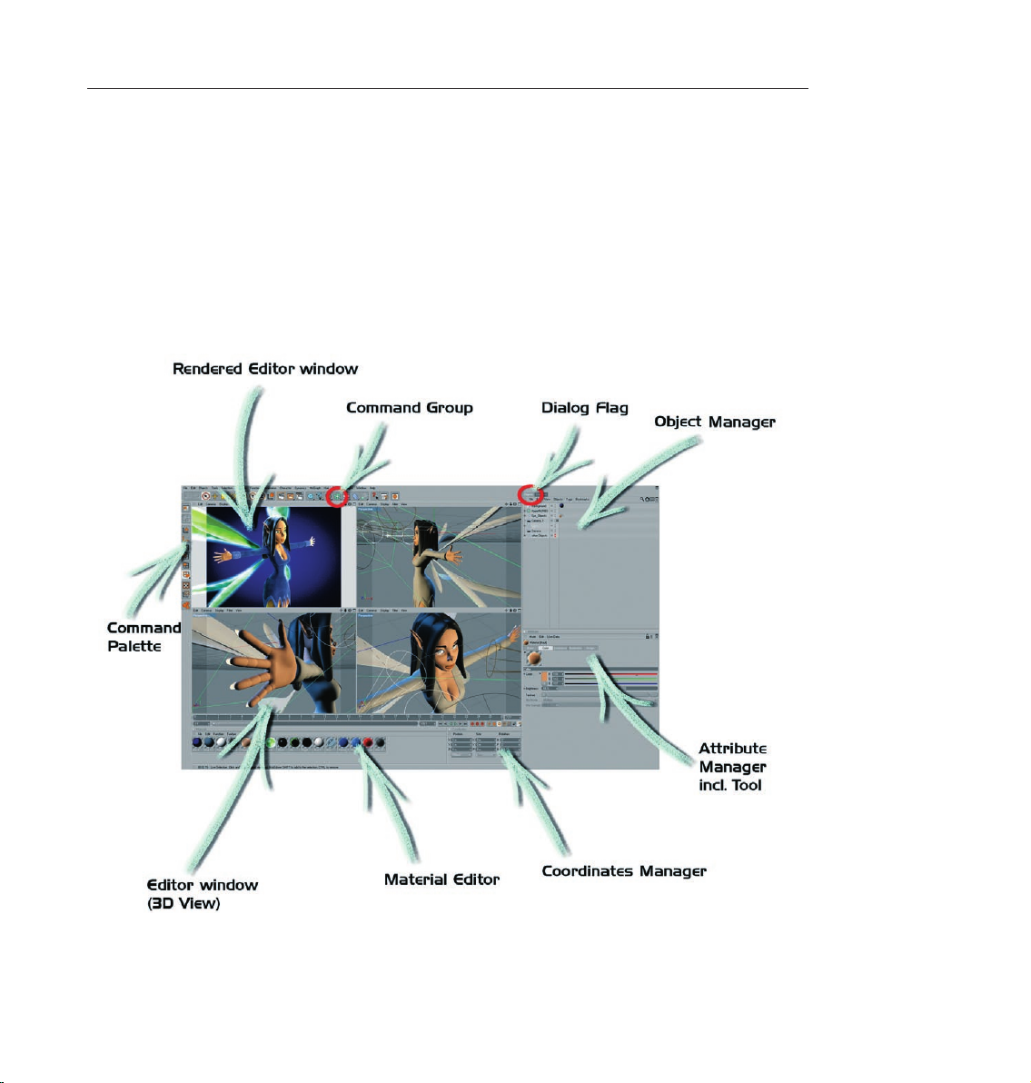
Let’ start with the most important step - starting CINEMA 4D. After starting CINEMA 4D you will see an image
similar to the following screenshot:
CINEMA 4D is divided into different working areas as follows: (starting at the top left clockwise)
Page 13
4 CINEMA 4D R10 Quickstart – Interface
The Editor Window shows all objects contained in the scene, for example polygon objects, cameras, lights and
bones and other deformers. You can render any view at any time to check your work.
A Group Icon contains several attributes for one group which can be accessed by clicking with the left mouse
button on the main icon. The group icon differs from normal icons in that you will see a small arrow in the
lower-right corner.
A Tab indicates different windows or managers which are layered over each other. In each window or manager
you will find different settings or attributes.
Page 14
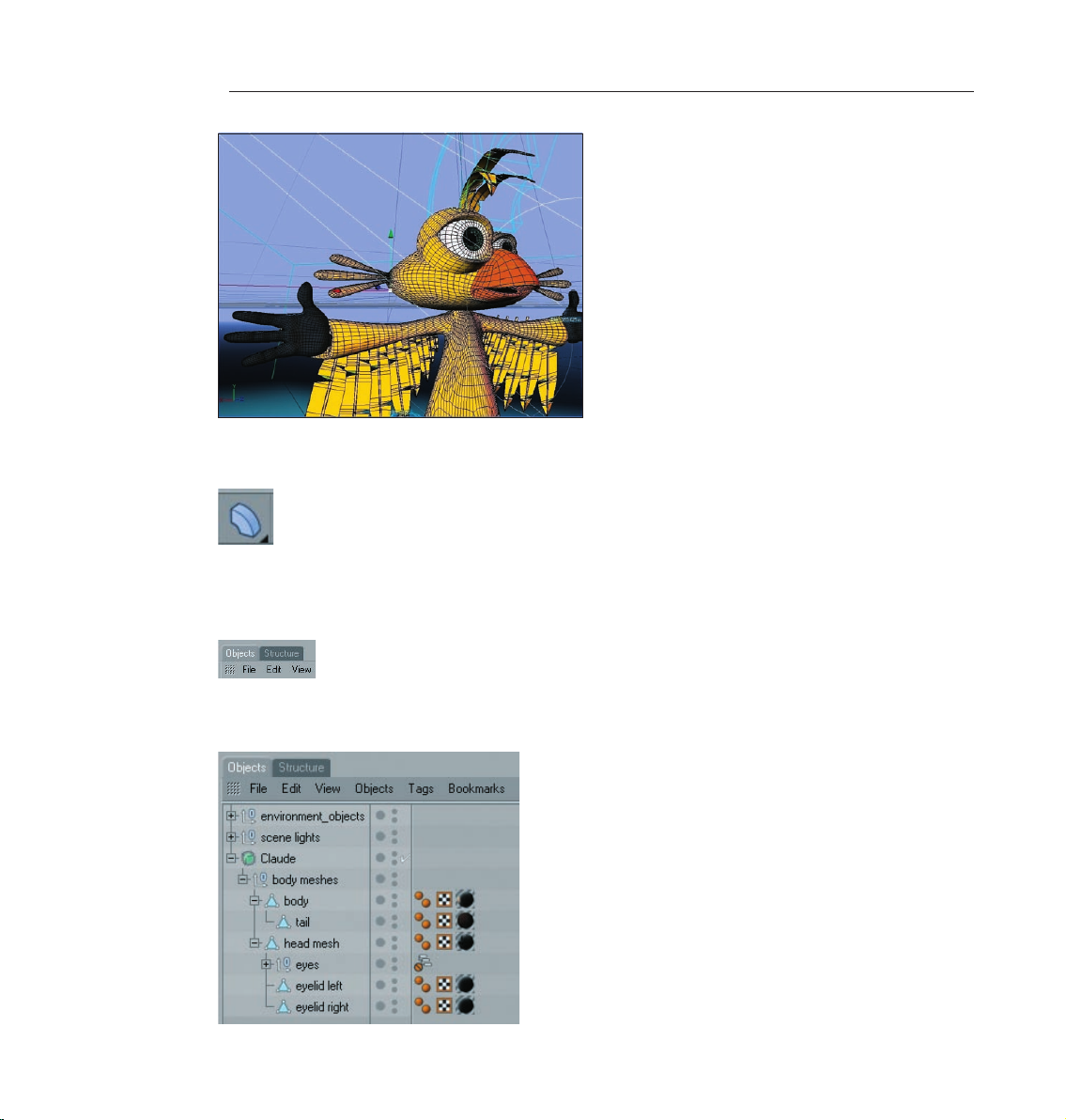
5CINEMA 4D R10 Quickstart – Interface
The Object Manager contains all of the scene’s objects. You use the Object Manager to set up a hierarchy,
assemble objects, set tags for objects (small icons to the right of the Object Manager let you assign an object
certain attributes), or to name objects. Included are polygon objects, lights, cameras, bones, deformers,
splines and null objects (objects without geometry).
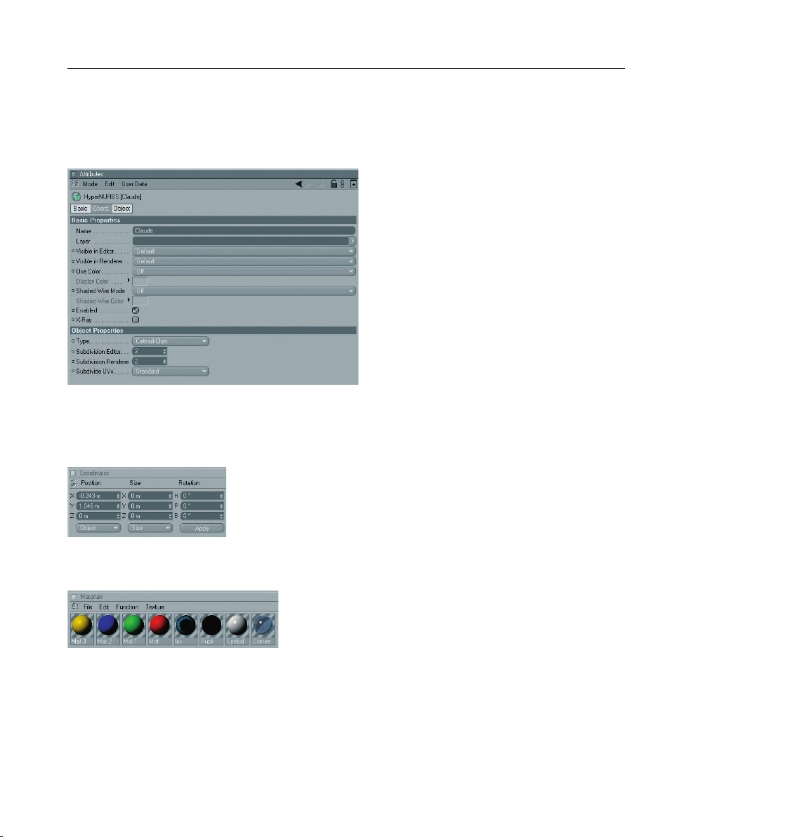
The Attributes Manager manages the attributes of each object or tool. This is where you can change the
strength of the HyperNURBS subdivision (more about that later) or an object’s visibility in the editor window.
The object’s coordinates can be found here as well as the tool setting such as the radius of the live selection
and the “Only Select Visible Elements“ option.
The Coordinates Manager lets you place, rotate or scale your objects. Enter the values in the given fields
and confirm your entry with the “apply“ button or simply press the return key.
The Material Manager contains all of your materials, including shaders, textures and other properties. Just
click on the material to see its properties in the Attributes Manager. Double-click the material to open the
Material Editor to make changes to its individual material channels. Illumination strength, type of specular,
strength of bump and more can be adjusted here as well. We’ll cover this in detail in a later chapter.
Page 15

6 CINEMA 4D R10 Quickstart – Interface
You can open up to 4 Editor Views simultaneously, giving you an overview of your scene from different
perspectives. You can view your scene in different modes ranging from gouraud shading (includes any lights
you have placed into the scene) to quick shading (displays your scene using only a default light, not lights you
have placed into the scene), wire frame and more. This lets you adapt your editor window layout to your needs
or your computer’s processor speed.
The Icon Palettes stretch down the left side and across the top of the editor window. The horizontal palette
contains the tools you will be using most often, depending on which module you are using at the moment. If
you are using the Modeling Layouts, for example, tools needed to work with polygons, edges and points will
be displayed. You can use one of the standard layouts or create your own Icon Palette. CINEMA 4D lets you
choose which layout you want to work with.
Now we will concentrate more on CINEMA 4D’s icon palettes to get you a little more familiar with them. The
following explanation will refer to the colored icons on the next screenshot.
Page 16
7CINEMA 4D R10 Quickstart – Interface
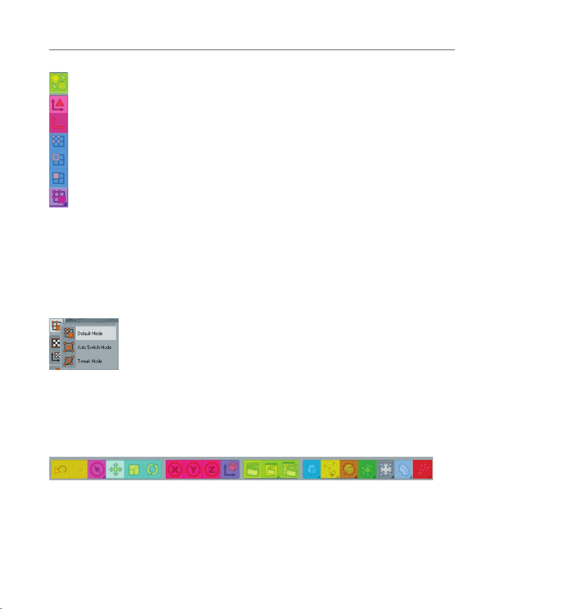
The image shows the left icon palette. At the very top you can see the previously mentioned predefined
layouts. Below that we have the (green) “Make Object Editable” button. This function lets a primitive be
transformed using points, polygon or edges. The editability of primitives is limited until they transformed!
You can determine size and number of segments but you cannot make any polygonal transformations. Next
we have the “Use Model Tool” and “Use Object Axis Tool” (red icons). You can move, scale or rotate a selected
object or rotate it around its own axis. The next three (blue) icons represent the “Use Point Tool”, “Use Edge
Tool” and “Use Polygon Tool”. In each of these modes you can either move, scale or rotate an object’s points,
edges or polygons or edit the object with CINEMA 4D’s integrated tools. The next (purple) icon lets you choose
between point, edge or polygon selection.
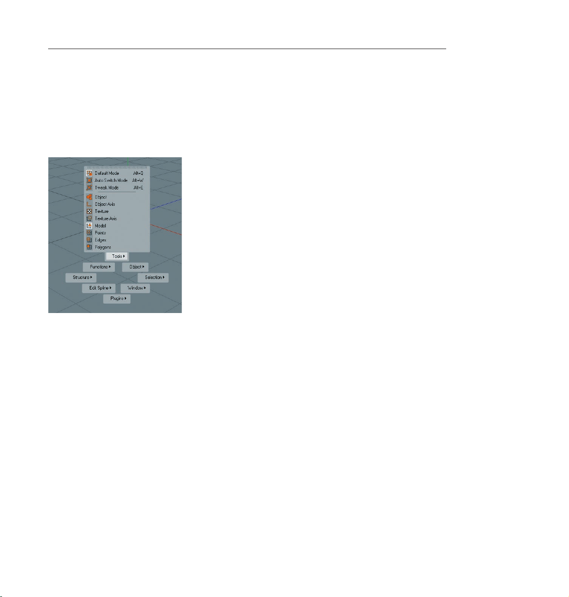
You select your points, edges or polygons in “Default Mode” by simply activating the corresponding points,
edges or polygons. In the “Auto Switch Mode“ CINEMA 4D recognizes whether your cursor is over a point,
edge or polygon. A click of the left mouse button selects the correct mode automatically. The “Tweak
Mode“ lets you do the same with an active move, scale or rotate tool. Now you know the icon palette’s most
important functions.
Now we will turn our attention to the most-used icons on the top palette.
On the left you will find the “Undo / Redo“ arrows (orange). This lets you reverse or repeat each step. You
can determine how many steps CINEMA 4D lets you undo by changing the presets in the main menu (edit /
preferences / document).
Page 17
8 CINEMA 4D R10 Quickstart – Interface
Next to the Undo / Redo icons you will see the “Live Selection“ (pink) tool. This lets you select your points,
edges or polygons for editing. The next three (turquoise) icons are pretty much self-explanatory. Use these to
move, scale or rotate your object or your object’s selected points, edges or polygons. When rotating, please
note that the center of the rotation will always be that of the active object (or camera).
The following three (red) icons let you lock & unlock the X, Y or Z axis. These settings let you determine the
direction in which your object will be edited. If only one of these icons has been activated it will only be possible
to move the object in that particular direction, unless you are using the object axis arrows, which are always
independent of the locked or unlocked X, Y or Z directions.
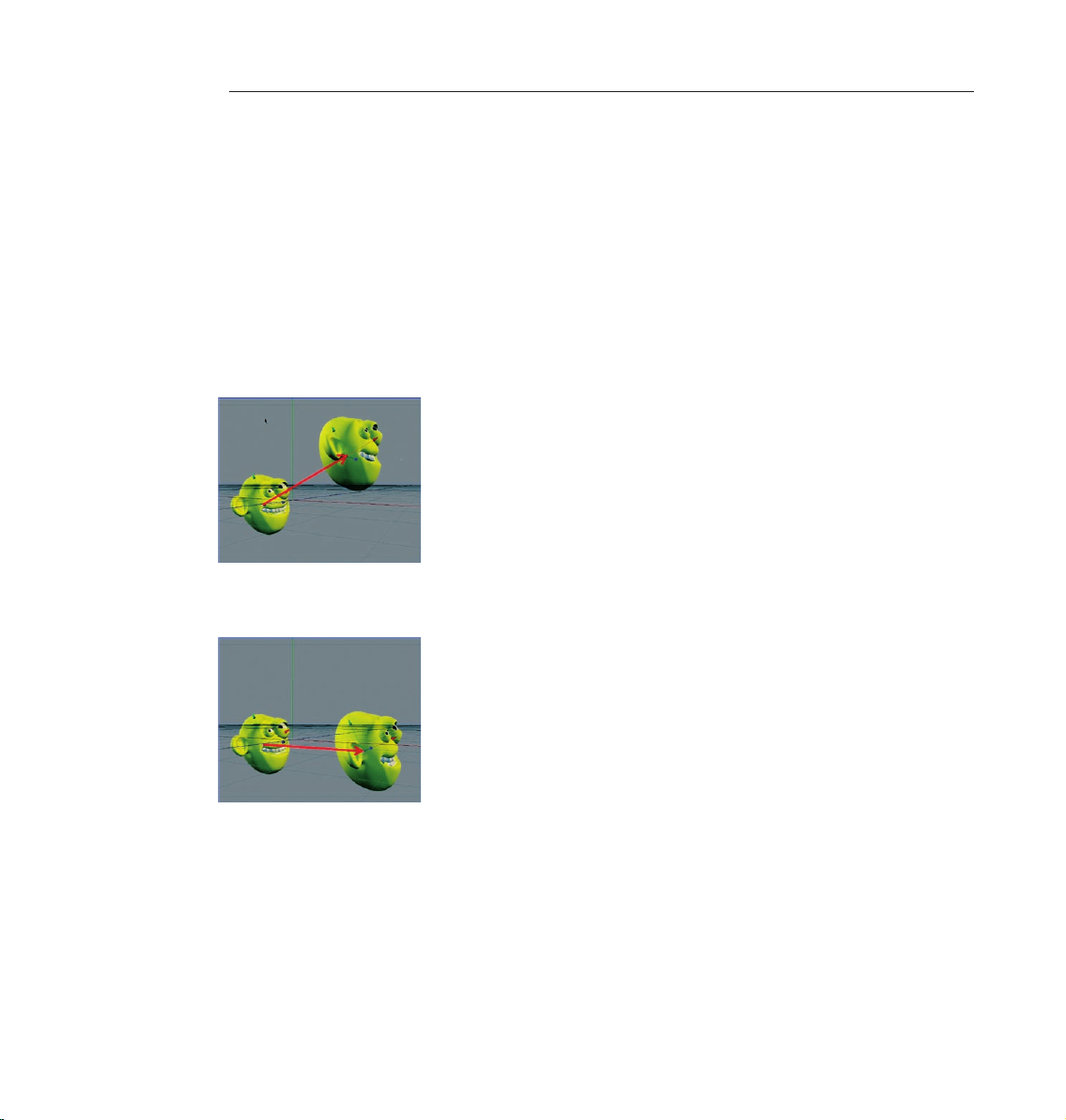
Th e n ext fu ncti on (p urp l e) le t s you s witch be t ween t he “Us e W orl d / Ob jec t Coord ina te
System“. Let’s assume the object axis of your wonderfully modele d head is slanted (whereas the term
“wonderfully modeled“ is open to interpretation in this case ;o). If you lock the X and Y axis, make the head
active and move it, you will notice that your model moves in the X-direction of the object axis.
Now select the world-coordinates instead and see how the object moves on the X axis parallel to the world
coordinate system.
This function can be very useful in modeling or animating your scene.
Now to the next group of three, the (red) Render Icons. The first function (Render Active View), with a
clapboard as a symbol, renders the image in the editor view. The rendering will be made using the settings
you have specified, with exception of image size and several post effects. Icon number 2 renders the image in
the “picture viewer” using the settings you have specified in icon number 3’s “Render Settings”. You can also
render animations in the picture viewer since the function “Render Active View” (as the name states) is only
meant for checking the scene in the active view.
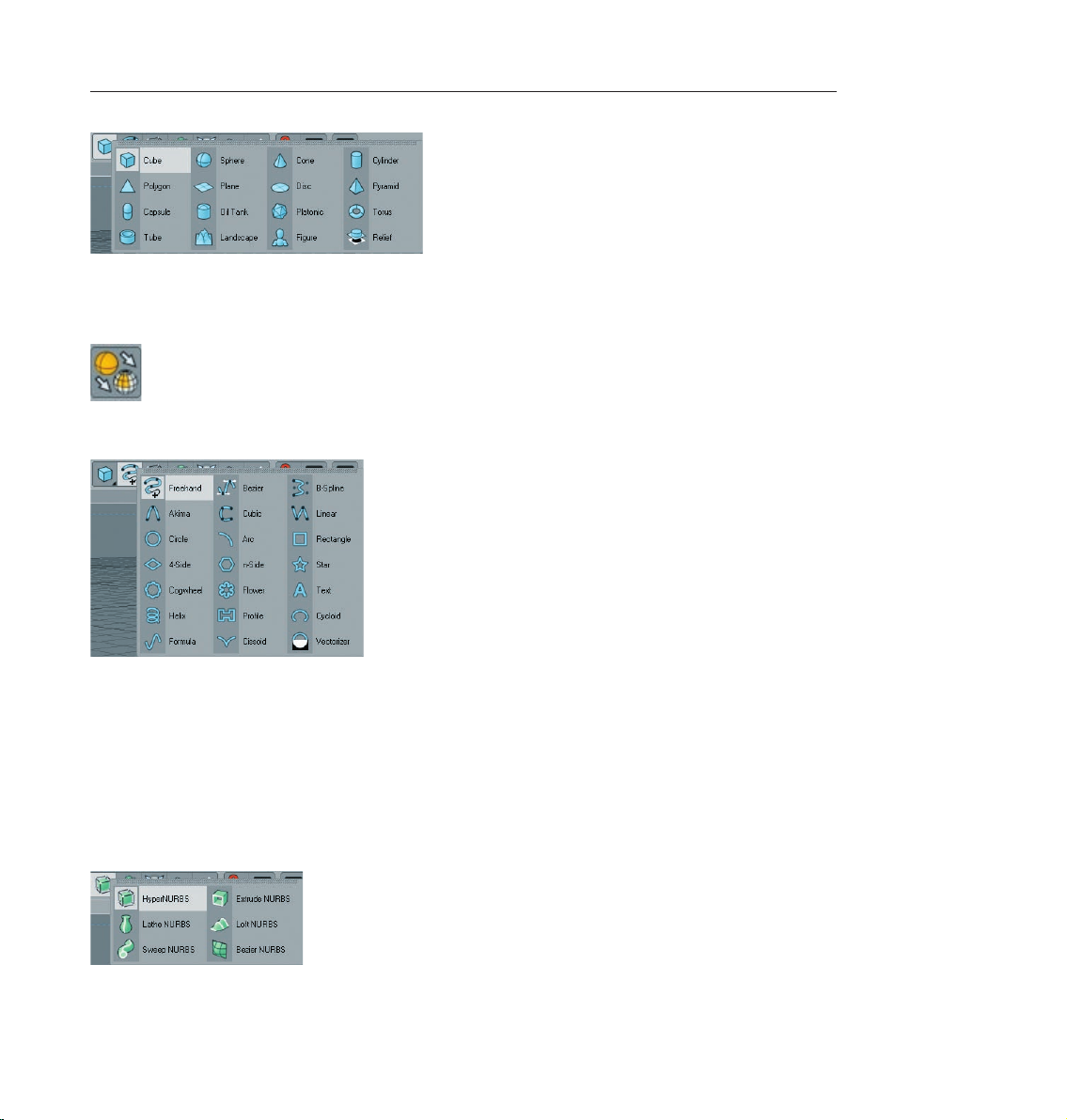
The next (blue) symbol is the group window “Add Cube Object“. It contains all of CINEMA 4D’s available
predefined parametric objects.
Page 18
9CINEMA 4D R10 Quickstart – Interface
One click and the world’s most used object is created – the cube. Click and hold to see all available parametric
objects. This is where you choose the initial shape you will need. And don’t forget! “Only parametric objects
that have been converted to polygon objects can be edited at a polygon, point or edges level!“
The yellow icon represents spline objects.
The term “spline“ has its origin in ship building. The wooden slats which were elastic enough to conform to the
shape of the ship’s hull were called splines. In the 3D world splines can be defined as “point-based curves“. A
spline “follows” several previously defined points while still retaining a curved form. This group window offers
several tools for drawing splines, as well as predefined shapes from which to choose. A spline can act as a path
for a camera to move along. Just draw a spline and let the camera move along its path. Splines can also be
used to model. To put it simply, splines are placed in a row as a wire frame over which a skin is stretched using
“Loft NURBS“, for example.
The next (dark orange) group icon hosts probably the most important CINEMA 4D object, the “HyperNURBS
object“.
Page 19
10 CINEMA 4D R10 Quickstart – Interface
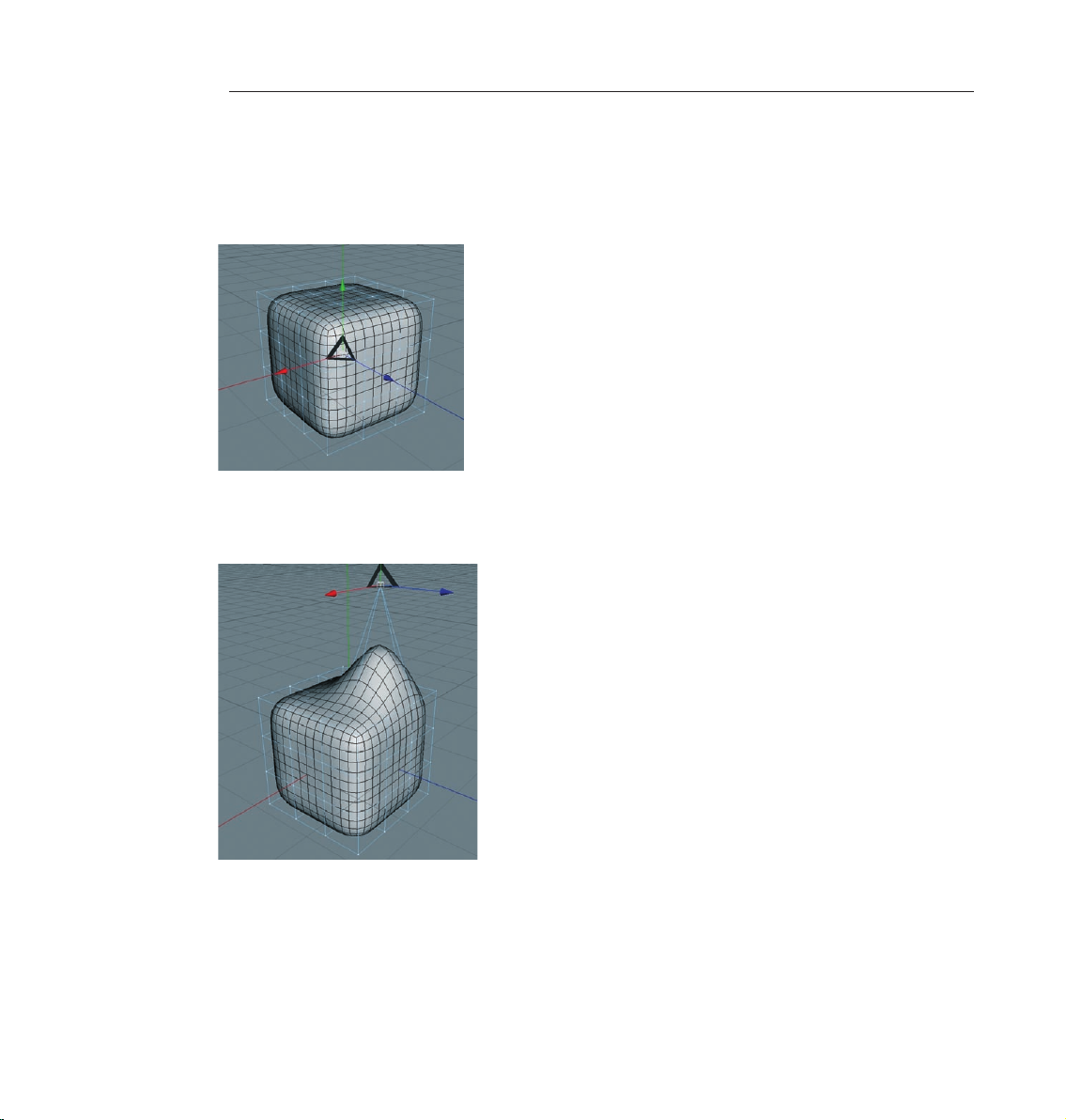
If a polygon object is a sub-object of a HyperNURBS object its polygon wire frame (mesh) will be subdivided to
a higher degree. Visually it will be comprised of many more smaller polygons than before the subdivision (the
object automatically looks softer / rounder) without losing the original mesh. As you can see in the next screen
shot: The outer mesh (light blue) shows the polygon cube’s actual subdivision. The finer inner mesh (black)
shows the subdivision of the HyperNURBS object.
The advantages, especially in modeling, are obvious. Since the object contains few points (edges / polygons)
that can be edited it remains very manageable. You can drag just one point of the original wire frame and the
HyperNURBS mesh, with its finer subdivision, will follow the point being dragged (see next screenshot).
If the polygon object were made up of such fine subdivision modeling, it would be much more complicated.
You would pull one point and only one point would be moved. All other surrounding points would retain their
position. You would have to move each one individually in order to achieve the desired shape. Haven’t quite
understood? No problem, in part 2 of our Quick Tutorial you will try modeling like this yourself so you can
learn the functions first-hand. Of course this group window contains several NURBS objects, of which you have
already gotten to know the loft and HyperNURBS.
Page 20
11CINEMA 4D R10 Quickstart – Interface
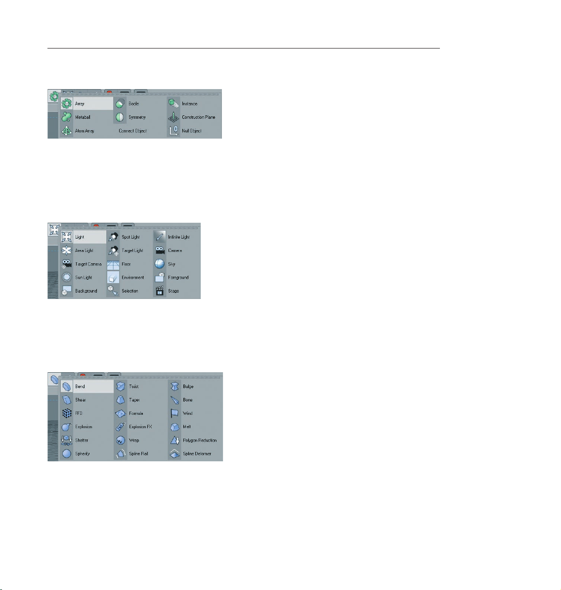
Let’s take a look at the objects behind the (green) “Function Objects“.
Here you will find, for example, the null object (object without geometry), the boolean object for boolean
operations (parametric and polygon objects can cut / slice each other), as well as the symmetr y object, which
can be unbelievably helpful in character modeling. You simply model one half of the figure and use the Add
Symmetr y Object function to mirror it and create the other half of the figure.
The second-to-last icon contains at least one object without which the best model would appear inconspicuous
and flat: the light (black & white).
The proper lighting of a scene is at least as important as the scene itself. You can make a better impression with
simple models and great lighting than you can with a fantastic model lit by a default light. We’ll go more into
detail about that later. Here you will find camera objects, the sun object and the environment object, among
others (adds a general color and / or fog to the scene).
The “Deformers“ can be applied with the objects of the last icon (light blue).
Use these to bend, deform or squash objects for modeling or animation. There are several helpful tools in this
group window. After you have worked your way through this tutorial you can try some of these yourself. You
can deduce what most of them do by their names (which appear at the lower left of your monitor when you
place the cursor over each icon).
Page 21
12 CINEMA 4D R10 Quickstart – Interface
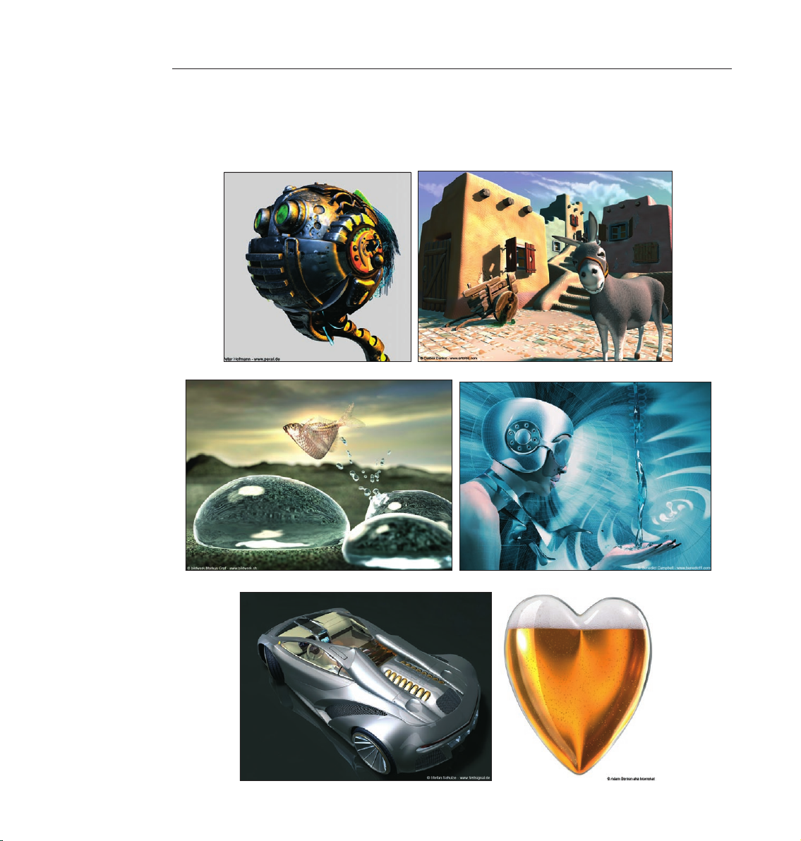
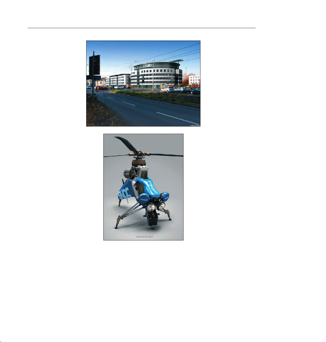
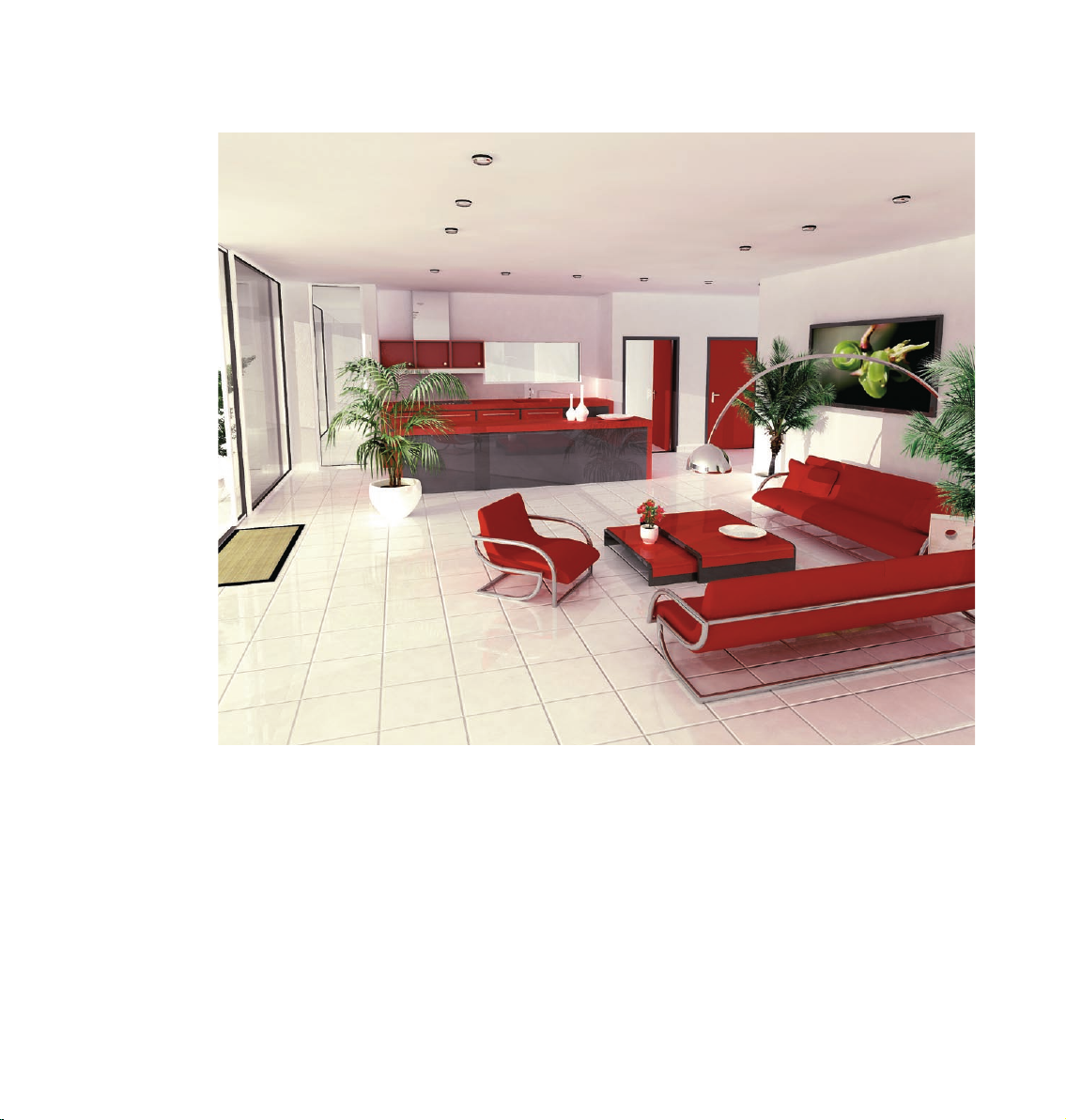
3. Sample Images
This is the “ooohs and ahhhs!” section. Take a look at these images and let them inspire you a little before we
move on to the hands-on part of this tutorial.
Page 22
13CINEMA 4D R10 Quickstart – Interface
Page 23
14 CINEMA 4D R10 Quickstart – Interface
4. Quick Tutorial – Arranging Objects
In order to give you a feeling of how CINEMA 4D works we will begin with the simple creation of a couple of
basic objects.
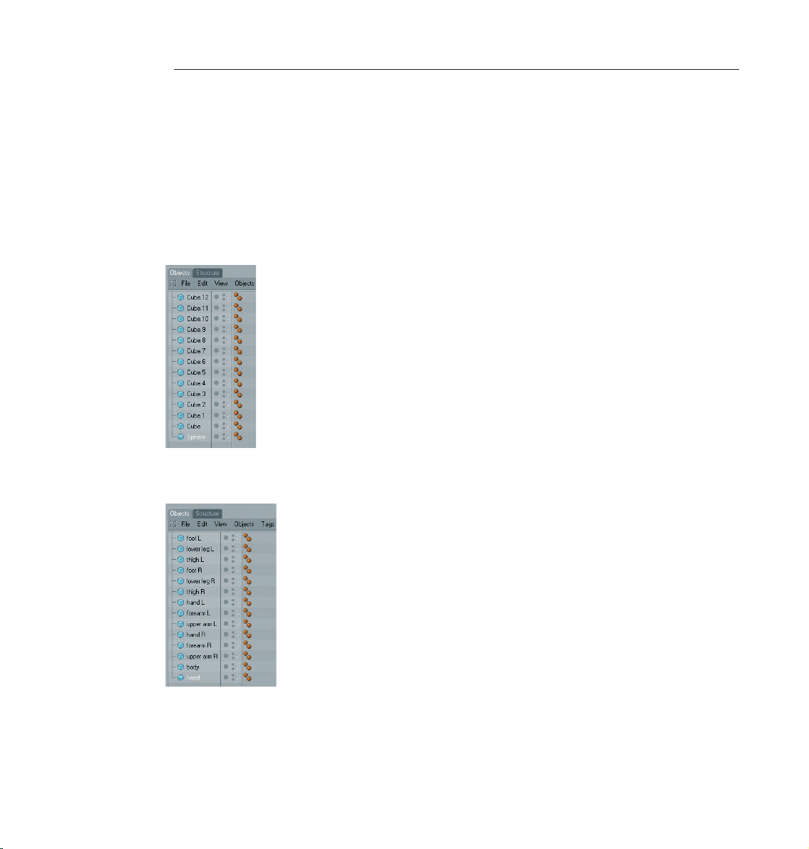
Create 13 cubes and one sphere using the main menu (objects / primitive / cube / sphere) or the group icon
“Add Cube Object“.
“13 cubes“ may give you the impression that we are preparing to create a mammoth project but don’t worry, we
are going to arrange the cubes into a little figure. When you’ve created the cubes you can see their alignment
in the Object Manager at the right.
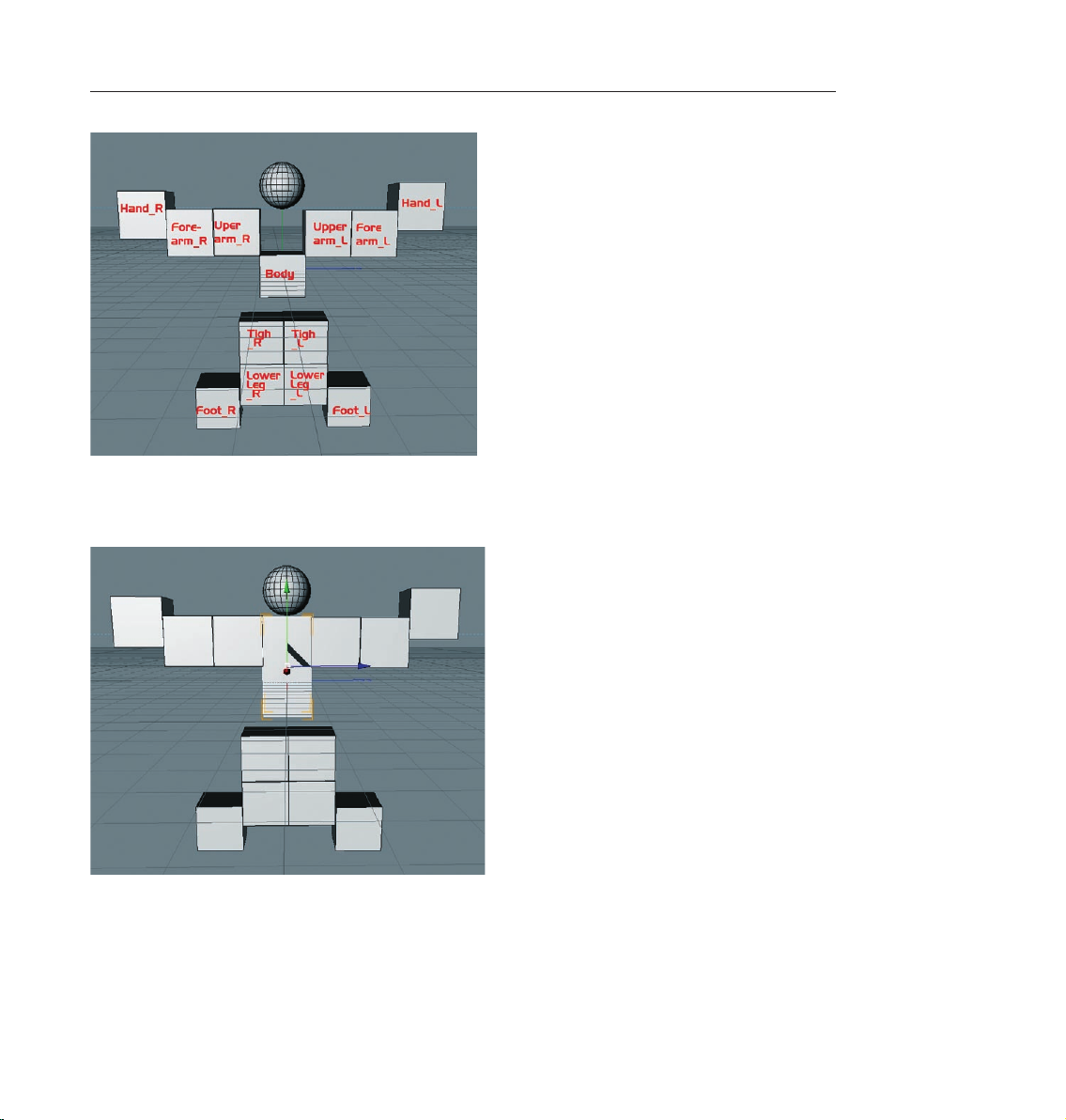
For better reference, give each cube a unique name (double click the current object name in the Object Manager
to open the context window for renaming the object). You can simply refer to the next screenshot.
Page 24
15CINEMA 4D R10 Quickstart – Interface
As you can see in the editor window, only one cube is visible. That’s because all cubes are located at the same
coordinates and are the same size, with the sphere in the center. Of course we will want to change this state
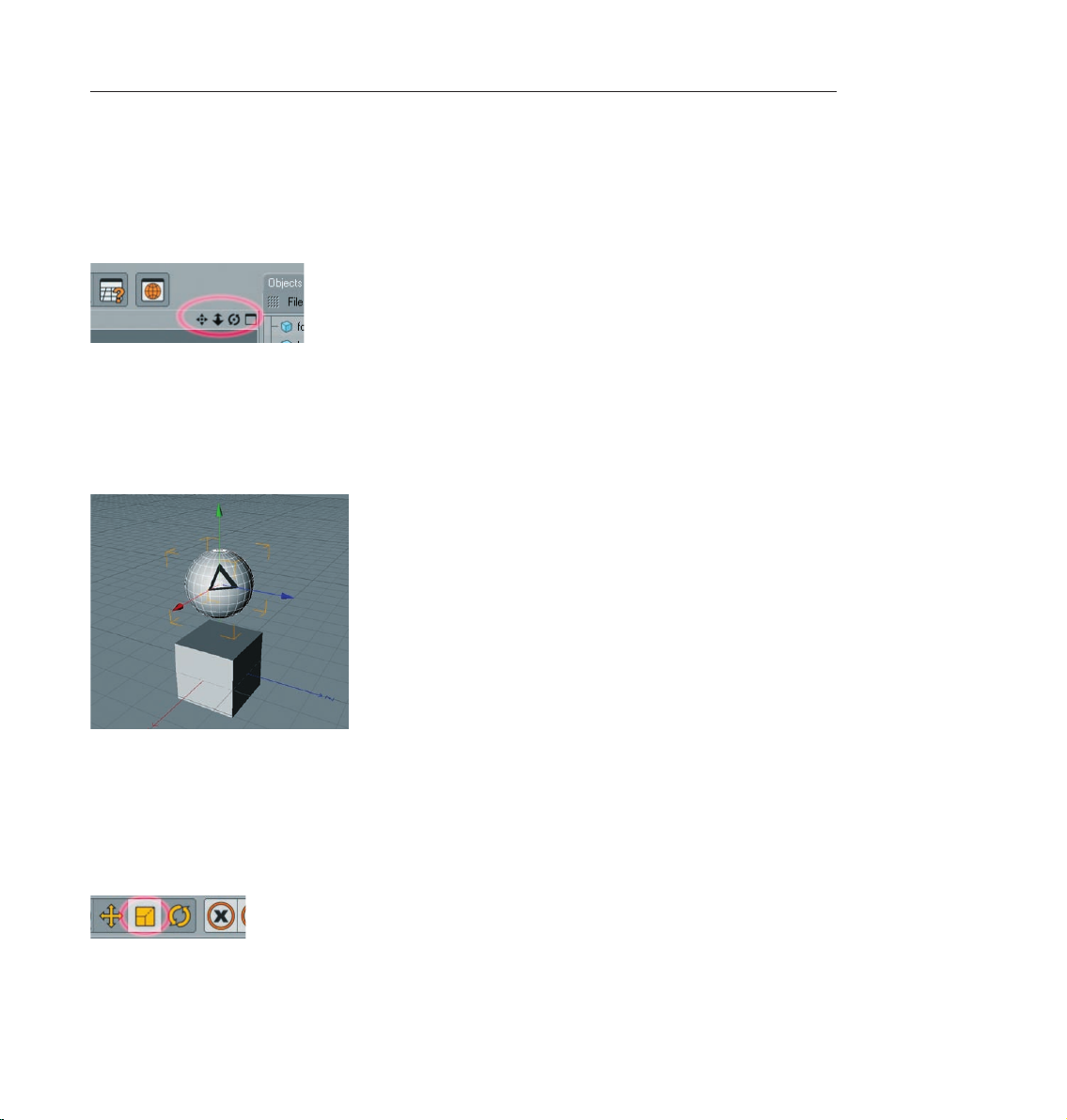
now, but first a quick introduction to navigating the editor window. How do I rotate and move my point of
view? Simple. Take a glance at the top right corner of the editor window. Here you will find four small symbols
with which you can change your point of view (of course we mean the point of view of the editor window, not
your personal point of view. We can have little influence on the latter.)
The first symbol (click – hold – move mouse) moves the view. The second symbol (foreshortened double arrow)
lets you zoom in and out and the third (curved arrows with a dot in the center) lets you rotate the scene.
Selecting the little rectangle to the right will divide the entire viewport into four views, giving you a better
overall view of the scene. Each of the four views has its own little rectangle which, when clicked, enlarges the
respective window. Zoom out a little and select the object “Head“ in the Object Manager. The head‘s axis will
be visible in the editor window. Drag the head‘s green object axis to a point over the cubes.
Each of the axis‘ arrows can be selected and dragged in its respective direction. This prevents the object from
being dragged in the wrong direction in the editor view (as opposed to clicking on the object itself and dragging
it). It is often impossible to see in which direction an object is being dragged in a 3D view. A similar method
of moving an object in a single direction is the previously mentioned locking of a specific axis in the command
palette. This prevents an object from being moved in the direction of an axis that has been locked unless you
click and drag one of the object’s own axis arrows. If no axis are locked, click on the “Scale“ tool on the icon
palette at the top.
The ends of the axis‘ arrows have changed form arrows to boxes. Dragging these boxes will scale the object along
that particular axis. Parametric objects (not converted polygon objects) will display little orange handles.
Page 25
16 CINEMA 4D R10 Quickstart – Interface
They make it possible to stretch and squash the parametric object on the respective axis
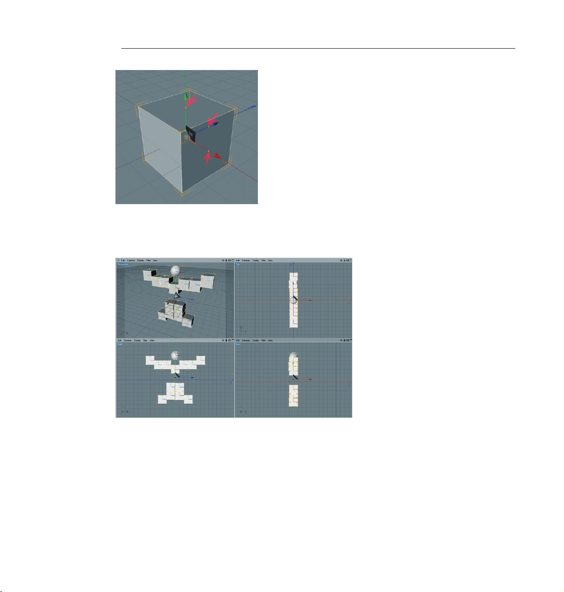
Now we’ll get to the nitty gritty part of this project. You now have enough basic knowledge to be able to
arrange the objects according to the following screenshots.
If you prefer, you can switch to a four-viewport mode (click the little rectangle at the top right of the editor
window). If the objects are displayed as wire frame objects you can switch to “Quick Shading“ or “Gouraud
Shading“ under “View“ in the editor’s menu. Now let’s get to work. Here’s a screenshot of the figure from the
front for reference.
Page 26
17CINEMA 4D R10 Quickstart – Interface
After you have arranged the cubes it still looks nothing like a “human character“. We have to rotate and stretch
the figure a little. Click on “Figure“ in the Object Manager and select the orange handle on the (green) Y axis.
Drag this handle until the top edge of the cube lies even with the arms.
Using the orange handles, select the cubes that make up the arms and adjust their size and position as shown
in the next screenshots.
Page 27

18 CINEMA 4D R10 Quickstart – Interface
If you want to scale all cubes of the arms at once you can do this as follows: with the shift button pressed, select
the objects “Lowerarm_L“, Upperarm_R“, Lowerarm_R“ and “Upperarm_R“ and press “C“ on you keyboard to
convert the objects and scale them with the “Scale“ function along the Y and X axis. As you can see, the orange
handles are not visible. Squash and move the figures arms and legs until it looks like the following image.
This should be no problem with the knowledge you have gained up to this point. To squash the legs, for example,
you can squash several objects at once instead of each one individually (as was the case with the arms).
Page 28
19CINEMA 4D R10 Quickstart – Interface
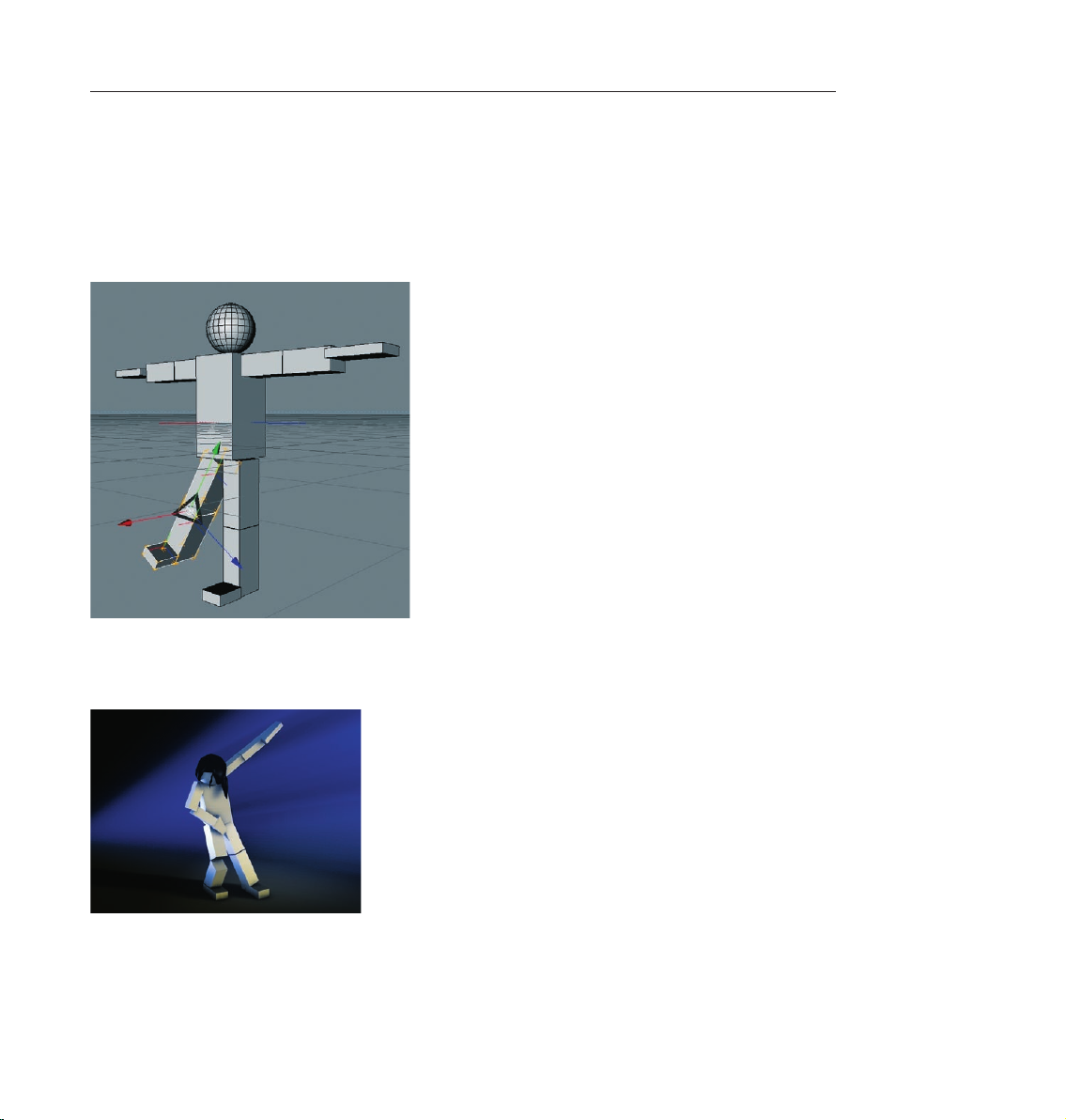
When you’re finished select the objects “Upperleg_R“, “Lowerleg_R“ and “Foot_R“. Once they are highlighted
in red in the Object Manager press the “G“ key on your keyboard. This groups all and makes all selected objects
children of a Null object. If you look at the Object Manager you will see the newly created Null object. Clicking
on the “+“ symbol will open the hierarchy and the objects we just selected will be shown. When the Null
object is selected, the axis of this Null object serves as the axis for all three leg objects. If this axis is rotated
all children of this Null object will be rotated. Move and rotate the Null object a little and you can make the
figure stick its leg out.
After you have selected the “Rotate“ function you can select the axis rings of the rotation sphere and rotate the
object into position. Try changing the figure’s position by using these different “moving“ functions. If necessary,
group objects into a Null object or select several objects at once in order to bring them into position.
Page 29

© Mat th ieu Rous s e l - ww w.
Page 30
21CINEMA 4D R10 Quickstart – Modeling
5. Quick Tutorial – Modeling
This is the most important part of this tutorial: How is a model built?
CINEMA 4D R10 has numerous tools that make modeling even easier and greatly simplify workflow.
A helpful function for quick navigation is the “General Popup“ which you can activate by pressing “V“ on
your keyboard.
A circular menu lets you choose from several menus in which sub-menus appear when the cursor is placed
over them. Play with the menu a little and find out how it can improve your workflow.
In order to show you the basic functions and the most common way to work with the modeler we will create
an eye for a comic character.
Let’s start with the creation of a cube, which happens to be the most-used primitive for modeling
(O bj ect s / Primitive / Cub e). Press th e “C“ key on your key board. By do in g this yo u have ju st
converted the parametric obje ct to a polygonal object. Most commands can be execute d via socalled “hot keys“ which, when used heavily, can spee d up your work in CINEM A 4D quite a b it.
Switch to the “Use Polygon Tool“ mode (on the command palette on the left) and select the “Live Selection“
tool (upper command palette). Make sure that “Only Select Visible Elements“ is active in the Attributes
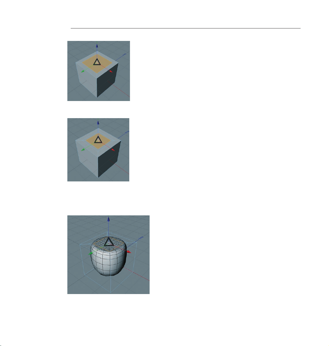
Manager. Mark the cube’s top polygon which will become brighter when you place the cursor over it and
turn orange when you have selected it. Click on this polygon with the right mouse button. Choose “Ex trude
Inner“ from the menu that appears (hot key “I“). With the left mouse button click on the top red polygon,
hold the left mouse button pressed and drag the mouse a little to the left. A second square should have been
created, as seen on the next screenshot.
Page 31
22 CINEMA 4D R10 Quickstart – Modeling
Repeat this procedure to create another square on the top of the cube.
Create a HyperNURBS object using the top command palette and make the cube a sub-object of the HyperNURBS
object. This will serve to subdivide our polygon object without us having to subdivide the original mesh. (Select
the cube in the Object Manager and drag it onto the HyperNURBS object and let go when the little arrow points
down.) Your cube will now look like this:
Grab the blue Z-axis in the editor window and drag it down until a relative large indentation has been made.
Page 32

23CINEMA 4D R10 Quickstart – Modeling
Rotate your view until you have a good view of the underside of the cube and switch to the “Use Point Tool“
mode. Now, using the “Live Selection“ tool, select all four points on the underside,
switch to the side view and drag these four points using the green Y-axis – drag them until the four inner
points of the indentation can be seen.
Page 33

24 CINEMA 4D R10 Quickstart – Modeling
If you created the indentation deep enough you may have already been able to see these four inner points. (In
the next screenshot you can see an X-ray view of the cube in which you can see the hidden points very well.
More on “X-ray“ at the end of this chapter).
We want to round off the shape a little more and to do that we will select the inner points. Even though they
are visible you won’t be able to select them with the “Live Selection“ tool. This is due to the fact that “Only
Select Visible Elements“ in the “Options“ menu of the “Live Selection“ tool in the Attributes Manager is active.
Deactivate this option and try the selection again. Now it’s possible to select the points. Be careful! If you forget
to turn this option off you might select all the points in the front of the object and accidentally select all points
at the backside of the object as well. The surface on the backside will be altered and you won’t notice until you
rotate the object at a later point. So always be aware of this option in the Attributes Manager!
Once you have selected all eight points on the object’s underside drag them along the green Y-axis a little to
the top to give the object a rounder look.
Page 34

25CINEMA 4D R10 Quickstart – Modeling
Cli ck on the Hype r N URBS object in the O b j ec t Man a ger an d dra g i t dow n a b it whil e
pressing the “Ctrl“ button on your keyboard. We have now duplicated the hemisphere. The same object is now
visible in the Object Manager twice.
Now select one of the HyperNURBS objects and select the “Rotate“ tool.
You can now adjust the object’s angle by using the “Rotation Rings“ on the “Rotation Ball“. Drag the blue Zaxis ring down 150 degrees.
Repeat this step for the other HyperNURBS object but only to 50 degrees.
Page 35

26 CINEMA 4D R10 Quickstart – Modeling
Position both hemispheres as pictured using the “Move“ function:
Here you can use the aforementioned locking axis function and switch to using the world / object coordinate
system.
Now create a sphere and move it into a position almost completely covering both hemispheres.
Page 36

Using the “Scale“ function you can resize the sphere to fit inside the two hemispheres.
27CINEMA 4D R10 Quickstart – Modeling
Congratulations! You have just created your first modeled object.
Page 37

28 CINEMA 4D R10 Quickstart – Materials
You can increase the HyperNURBS object’s subdivision to give our model a smoother look. Simply select the
respective HyperNURBS object you want to smooth and set the “Subdivision Editor“ in the Attributes Manager’s
“Object“ menu to a higher value. The parameter “Subdivision Renderer“ is only responsible for renderings in
the picture viewer.
Our eye still looks a little blind. We’ll change this in the next chapter by adding a pupil texture. Before we do
that, though, we’d like to give you some more modeling tips.
Adjust the influence of HyperNURBS: Select both cubes and several polygons in the Object Manager. Press the
“V“ key on your keyboard, select the “Structure“ menu and click on “Weight HyperNURBS“. If you now click
anywhere in the editor window with the left mouse button and drag the mouse to the right you can determine
the strength of the HyperNURBS for the selected polygons. If you are not satisfied with the result and have
unclean edges try this function in the “Use Edge Tool“ mode. This will give you better results.
If you should want to sel ect points that li e with in an obje ct or if you have “Only Sele ct Visible
Elem ents“ de act ivate d and wa nt to avoid accidentally se lec ting p oints on the ba cks ide of th e
object simply activate “X-ray“. You will find this function under display / x-ray. This lets you see through the
object and see ever y point (Polygon / Edge). Accidental selection of hidden points is thus not possible and
you have an excellent over view of the inner points of the object which would normally not be visible from the
outside.
6. Quick Tutorial – Materials
A well-modeled object can make a mediocre impression if the right tex tures aren’t used. Tex tures give a
model color, highlights, structure and other important surface properties. A texture placed into the bump
channel, for example, gives the object’s surface an uneven, bumpy look without actually altering the geometric
structure. This effect can be used to imitate skin wrinkles, scars or the surface of an orange. The displacement
channel works in a similar fashion, only that it actually does change an object’s geometric structure. Using
the luminance channel you can give an object’s sur face a self-illuminating property or integrate a SSS effect
(sub-surface scattering) which lends the surface a slight translucent / reflective look, like human skin or candle
wax, for example. In short: Textures have the same significance as the outer shape of an object because they
are necessary for achieving the desired atmosphere, coloring and surface structure.
We will begin with a brief introduction to the individual material channels:
Color: This is where the material’s color or the base color for the texture is set.
Diffusion: This channel makes your texture “irregular“. Through the application of a noise shader or a texture
your object receives a dirty or dusty look. If desired it can also influence the specular, reflection and luminance
channels respectively.
Luminance: The material is given an illuminative property which is also taken into account in the radiosity
Global Illumination calculation.
Transparency: This is where you determine the material’s opacity.
Reflection: Gives the material a reflective characteristics.
Environment: A material is used to simulate an environment reflection.
Page 38

29CINEMA 4D R10 Quickstart – Materials
Fog: This channel lets you apply a fog or cloud property to a material.
Bump: Uses an optical trick to translate light and dark elements of a texture or a shader to simulate the height
and depth of an uneven surface. Scars, wrinkles or scratches can be simulated using this channel.
Normal: This channel is meant for use with “normal textures”. Normals give a low-res polygon object a hi-res
look when RGB textures containing the required properties are applied. This lets a hi-res polygon object be
replaced by a low-res object, thus saving a lot of render time and offering the same visual result.
Alpha: A texture’s transparency is determined by a material’s light and dark areas. Black equals a transparency
of 100% and white makes it opaque.
Specular: This determines a material’s specular properties.
Specular Color: This determine s the col or of the mate rial’s specularity and can be influenced by
a texture.
Glow: Gives the object a self-emitting glow.
Displacement: Deforms an object using light and dark values (calculates differences in height). Do not confuse
this with the relief channel which only imitates an uneven surface.
Since our eye still looks a little pale we will liven it up a little with the application of textures and shaders. If you
skipped the modeling chapter simply open the C4D_eye_Texture.c4d file. Now we have the eye we created in
the previous chapter. You can see in the Object Manager to the right that the object does not yet have a texture
applied to it. We will do something about that now.
Click on file / new material in the Material Manager at the lower left.
Page 39

30 CINEMA 4D R10 Quickstart – Materials
A standard material has been created. If you click on this material its properties will be made visible in the
Attributes Manager to the right. In the “Basic“ menu you can determine which channels should be activated
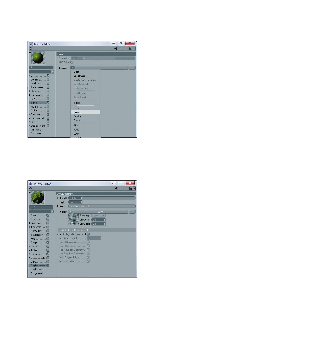
for this material. Go ahead and activate the Bump channel. As soon as you have done that a new menu button,
“Bump“ will appear. Now click on the menu button “Color“ and load a texture into the material by clicking
on the small arrow next to “Texture“. Choose “Load Image“ and load Iristexture.jpg. In the mini-preview of
the Material Manager at the lower left of your screen you will see the texture displayed as soon as it has been
loaded. This gives you a good over view of the materials being used in the scene.
Repeat this procedure for the “Bump“ channel and load Iristexture_bump.jpg into the channel. This JPEG
contains the gray scale version of the iris texture which we need to create a relief effect for the surface. You can
also choose “Filter“ and load the color texture here and set its saturation to 100%. This saves you from having
to load a second image. The bright areas of the image will later appear to be raised on the object and the dark
areas of the image will appear to be somewhat indented. A true deformation of the object will only take place
in the “Displacement“ channel. The “Bump“ channel does not alter the polygon’s surface but uses an optical
illusion to give the surface its structure.
Click on the material in the Material Manager with the left mouse button and drag it onto the object eyeball
in the Object Manager. (When you drag the material over the object you can let go once the little black arrow
points to the left).
You have probably noticed that the eyeball brightened somewhat after you applied the material but you aren’t
able to see the actual texture. We still have to change the offset properties and the mapping size so the texture
will be aligned properly on our object. At the moment the actual image of the iris is lying distorted on the left
side of the eyeball. You can check this by making both HyperNURBS eyelid objects invisible for the editor. To do
this click on the top small gray dot to the right of the object in the Object Manager.
Click on the dot again and it will turn green, which makes the objects visible again independent of the
visibility settings of any parent object. The dot directly below has the same function except that it affects the
rendering.
Page 40

31CINEMA 4D R10 Quickstart – Materials
Once you have made the eyelids invisible and have rotated the view a little the eyeball should look as follows:
Switch the visibility of the HyperNURBS objects back by clicking again on the dots next to the object in the
Object Manager, making them gray. Click on the “Texture Tag“ at the right of the Object Manager next to the
object. It’s the material that we applied to the eyeball. You can recognize it in the mini preview of the texture
in the Object Manager.
Once you have selected it you will see its parameters in the Attributes Manager. Adopt the settings you see in
the next screenshot:
We have just aligned the texture on the eyeball mesh by changing the “Length X“ and “Length Y“ parameters.
The offset setting put the texture in the correct position. If you rotate your view again you will see that the iris
texture is positioned correctly.
Page 41

32 CINEMA 4D R10 Quickstart – Materials
(Tip: If you want to undo an accidental change to the view just press “Ctrl+Shift+Z“). This function is useful if
you have inadvertently rotated the perspective view instead of the editor view. You can also select edit / undo
view in the main menu of the editor view.
Our eye may be able to look at us now but the eyelids still make it look a little too gray. We will change a couple
of settings that will give the eye a reptilian look.
Create a new material (Material Manager / File / New material) and double click the new material. This will open
a dialog window for the material where we can make the necessary changes to this material. Click on “Color“
in the material channel and copy the settings of in the following screenshot.
Click on “Color“ in the material channel and copy the settings in the following screenshot.
We will give the material a green tone and lower its brightness to 50%. Check the box next to the “Bump“
channel. Click on the little light gray arrow in the checkbox next to the word “Texture“ and select “Noise“.
Page 42
33CINEMA 4D R10 Quickstart – Materials
Click on “Noise“ and on the following dialog page set the global and relative scale factors each to 30%. This
reduces the size of the bump-noise mapping which will result in a finer depiction of the bump map.
Check the box next to “Displacement“ and repeat the previously mentioned steps for the bump channel but
set the global and relative scales each to 150%. This will increase the size of this channel. Click on the word
“Displacement“ to return to the displacement channel’s main menu.
The displacement channel deforms the polygon mesh according to the bright and dark areas of an image. Bright
areas of the texture raise the polygon mesh and dark areas lower the mesh. This lets you create a wide variety of
shapes without having to model such a complex surface, thus saving you a lot of time. The ornamental facade
of a house or the relief of a sword handle are good examples. The possibilities are endless.
Page 43

34 CINEMA 4D R10 Quickstart – Materials
Close the Material Editor window and set the HyperNURBS subdivision of the eyelids to at least 4 in the editor
(Click on the respective HyperNURBS object and change the settings in the Attributes Manager) and apply the
new material to the eyelid objects. Render the view (Ctrl+R). The result should be at least somewhat similar a
reptile’s eye.
You h ave s e en how you ca n g et quic k r esu lts w ith out hav ing t o cr eat e a com ple x t exture.
CINEMA 4D’s integrated shaders and channels offer so many possible variations that you will never be able
to try them all. Play around with some of the parameters, add a couple of channels and find out how they
influence your renderings.
Here are some more tips about channels for you to tr y:
Got dirt? CINEMA 4D does! Most objects in the real world are not as clean and immaculate as they might appear
in CINEMA 4D. Real stone figures show signs of weathering over the years and dirt has settled in the wrinkles
and cracks. You can simulate such “dirt“ very easily with CINEMA 4D (if you own the Advanced Render module)
by activating the Dirt option on the Render Settings’ Ambient Occlusion page..
If you own the “Advanced Render“ module (or are testing the CINEMA 4D demo version) you can render human
skin, for example, very realistically. The shader Surface Scattering makes it possible. By placing this shader in
the luminance channel (effects / sub-surface scattering) the effect is created when rays of light meet a slightly
transparent object. Some rays infiltrate the object further and are dispersed, others are directly absorbed or
bounce off. Further possible uses for this effect would be for materials such as plastic, milk, candle wax or
figurines made of jade.
You can load black & white textures into the alpha channel to influence the material based on the texture’s
brightness, similar to the way you would use them for the bump or displacement channels. The texture’s black
areas would be rendered with a transparency of 100%. As the texture becomes brighter the transparency is
reduced accordingly. White would have a transparency of 0%
If you choose “Shader“ instead of “New Material“ under “File“ in the Material Manager you will see a list of
bhodiNUT 3D shader presets. The advantage of these shaders is that you don’t have to worry about mapping
your texture or seams in your texture because a 3D shader will be calculated for the 3D space. Here are a couple
described in detail:
Cheen: Generates an electron microscope effect good for the depiction of bacteria or mites.
Page 44

Danel: Very good for simulating high-gloss finish Banzi: Lets you depict various types of wood.
35CINEMA 4D R10 Quickstart – Materials
Banji: Calculates complex lighting situations with glass and even makes rear-projection (shadow casting) on
partially transparent materials such as rice- or canvas paper possible.
Page 45
© www.bediff.com
Page 46
37CINEMA 4D R10 Quickstart – Lighting
7. Quick Tutorial – Light
If you are already familiar with lighting a scene in the “real world“ then you will feel right at home with the
CINEMA 4D light objects. They can do everything “real“ lights can do – and quite a bit more. In this tutorial
we will set up a 3-point lighting arrangement. This type of arrangement is used often in portrait photography
to achieve an even lighting and is an excellent method for lighting an object quickly and professionally in the
3D world
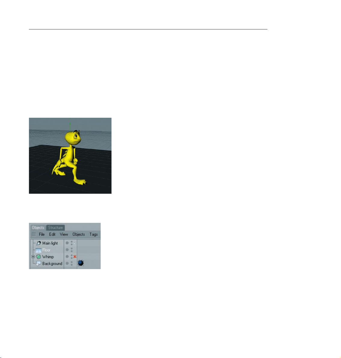
Adjust your editor view so the entire figure is visible to you.
We want to light up our little character. Open the file “AS_Whimp_Start.c4d”. Create a floor object (Objects
/ Scene Objects / Floor) and position it so the figure is standing on it.
A 3-point lighting arrangement begins with setting a key light. As the name suggests, this light emits the main
lighting for the scene and will cast the main shadows. Create a light object (Objects / Scene / Light). Name it
“Main_Light“ in the Object Manager.
CINEMA 4D has several different types of light sources. The key light will always be created by default. A
point light emits from its center in all directions. For our key light we will need a spot light which we can aim
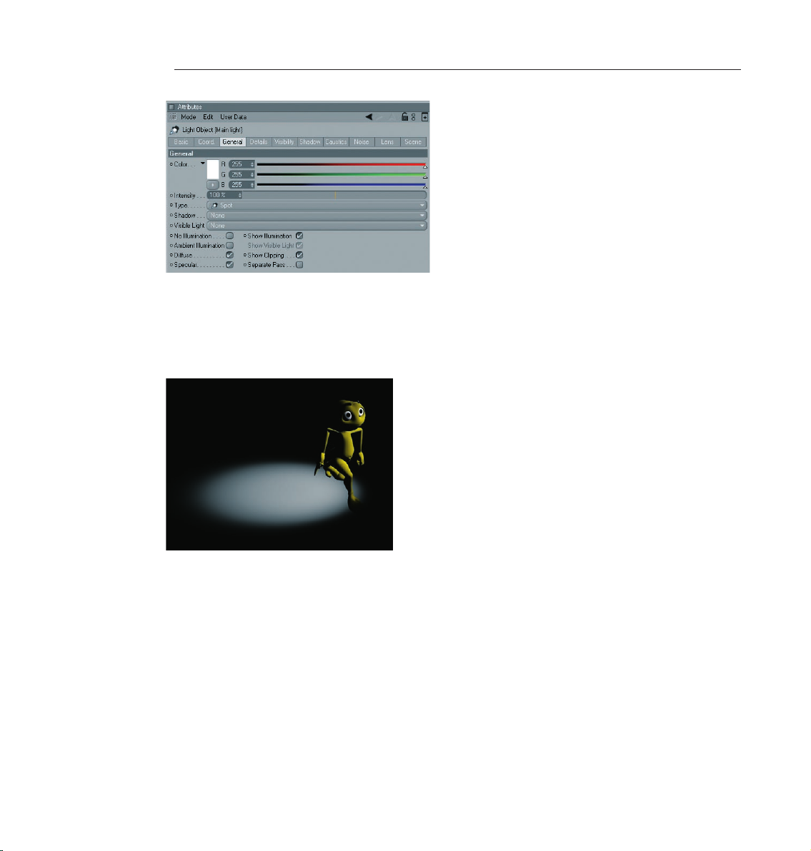
directly at the object.
To make the key light a spot simply go to the Attributes Manager and switch the light from “Point“ to
“Spot“.
Page 47
38 CINEMA 4D R10 Quickstart – Lighting
Now our light source has been transformed to a spot. A spot acts like a flashlight. CINEMA 4D offers spots
with square and round cones of light. This cone is visible in the editor and can be manipulated. Now we will
aim the spot at our figure.
Position the light at the following coordinates in the Attributes Manager: X=300, Y=580, Z=-300 at an angle
of H=45, P=-45 degrees. Render the scene.
The light now falls at an angle onto our object. Of course the exact position of the light is strongly dependent
upon the camera’s angle. Unfortunately the light is not casting a shadow, letting the figure look like it’s floating.
CINEMA 4D’s lights have an advantage over real light in that you can choose which kind of shadow, if any, they
should cast - a plus for any studio photographer.
In the “General“ menu of the Attributes Manager, set the light’s shadow to “Shadow Maps (Soft)“. We don’t
want the shadow to be completely black so we’ll make it a little transparent.
In the “Shadow“ menu, set the shadow density to 50%. Select “1000 x 1000“ as the shadow map. Render the
scene.
Page 48

39CINEMA 4D R10 Quickstart – Lighting
CINEMA 4D offers three types of shadows: “RayTraced (Hard)“ – a shadow with sharp edges, “Shadow Maps
(Soft)“ – a shadow with soft edges and “Area“ – a shadow that becomes softer the further it’s away from the
object, resulting in the most realistic shadow effect. Try the other two shadow types. Careful, the area shadow
can take a long time to render! The larger shadow map allows the shadow to be rendered more accurately.
The light’s cone is a little too small. We will change this as follows:
Switch to the details menu in the Attributes Manager and set the “Inner Angle“ to 30 degrees and the “Outer
Angle“ to 100 degrees.
You will see the result in the editor right away. You can also edit the light’s cone by dragging the orange
handles.
Page 49

40 CINEMA 4D R10 Quickstart – Lighting
Now we’re happy with our key light. Next we will create a more even lighting by brightening our figure a little
from the other side.
Create another light source in the scene and name it “Brightener“. Place it at the following coordinates: X=
-360, Y=225, Z=-230 and at an angle of H=-20, P=-10 degrees. Select “Area“ as the type of light.
Since the brightness of the lights in the scene is additive, we must “dim“ the brightener a little.
Reduce the “Intensity“ in the “General“ menu to 40%.
This area light illuminates the figure from a different angle and softens the contrast somewhat. It won’t cast a
shadow since this would cause “crossing“ of the shadows and make the object look bad.
The scene is now pretty evenly lit, but we want to give it a little more pep. Create another light source, name
it “Color“ and, in the Attributes Manager, set its type to “Infinite“. Set its color to turquoise and set its H angle
to -160.
Page 50

41CINEMA 4D R10 Quickstart – Lighting
The position of an infinite light is irrelevant since it always lights your scene in the direction of the Z axis. This is
why we will leave it at the point at which it was created. It gives our Amphibian an interesting color edge and
sets him off of the background a little.
Your scene’s mood can be changed by simply changing the color of some of the lights used.
That completes our classic 3-point lighting arrangement. Now the real work starts. If the scene has a background,
which is often the case, it will have to be lit as well. With the proper use of point lights details in the scene can
be “brought to light“ very nicely. But don’t overdo it. With good lighting, less is often more. Only add lights
when necessary and if the scene can actually benefit from them. Two more tips before we end: If you have
several lights in a scene and are not sure which light is lighting what, simply make all other lights invisible in
the Object Manager. The light which remains will be the only one visible in the editor.
There is a trick how you can determine how to best light which objects in your scene. Select the desired light
in the Object Manager and activate Link Active Object in the editor view’s Cameras menu. Selecting this option
lets you view the scene from the point of view of an active object, in our case the light. Moving the editor view
will automatically change the position of the light when in this mode. This way you can see how the change of
position of the light affects the lighting of the object in realtime (Gouraud Shading must be active in the editor
view). Once you have reached the desired angle and position you can return to the editor view by selecting
Editor Camera from the Cameras menu.
Page 51

com
© Benedict Campbell - www.benedikt1.
Page 52

43CINEMA 4D R10 Quickstart – Animation
8. Quick Tutorial – Animation
With but a few exceptions CINEMA 4D lets you animate every attribute of an object. This means you can alter
any attribute in the Attributes Manager over time, whether it’s an object’s Y-coordinates, the color of a light
or the strength of an explosion object. By animating different attributes you can easily add complex animation
effects and visually attractive scenes.
Let’s look at a “quick & easy“ example just to demonstrate the basic principles of animation.
Begin by opening a new (empty) scene. Create a cube (Objects / Primitive / Cube).
You will see a turquoise slider at the bottom of the editor window next to which the frame (time) is shown.
This is known as the time slider. By moving this slider you can jump to a different point (time) in the animation,
similar to fast-forwarding or rewinding a film. You can also use the turquoise arrows to the right of the slider
to play the film at a predetermined speed.
Fur ther to the right you will see the “re cord“ button (the orange button furthest to the lef t with
the key icon). You can use this button to record cert ain objec t attributes. Use the but tons to the
right o f t he rec or d button to set these at tribu te s. W it h the se but tons you ca n “key“ (reco rd)
the position, size, rotation, attribute and / or point-level-animation of an object at any given time in the
animation.
Make sure the time slider is to the left, on 0. Deactivate all symbols to the right of the red buttons, except the
first (position), and click on the record button.
We have now told the cube that it should stay at its position of 0 / 0 / 0 starting at time / frame 0. In other
words, we have generated a key that contains the information on the position of the cube at time / frame 0. We
will tell you later what exactly a keyframe is. Where can you find this ominous key? It’s located in CINEMA 4D’s
“timeline“. The timeline is where you can change the position of the keys on the timeline, change the values
they contain, delete them, set new keys and much more.
Switch to CINEMA 4D’s animation layout (Window / Layout / Animation).
Take a look at the timeline at the bottom of your screen. You will see the cube along with a “track“ for its
position. This track contains three “sequences“ (one for every recorded coordinate) with a light blue box at
time / frame 0 – a key.
Page 53

44 CINEMA 4D R10 Quickstart – Animation
Slide the time slider to frame 90. Move the cube along its blue Z-axis (back) a little. Click on the record button.
Three more keys will appear on the timeline, this time at frame / time 90.
When you move the ti me slider you can see the cube move betw een the tw o rec or ded point s.
Congratulations, you’ve animated the cube! Using the orange button to re cord an object ’s changing
at tribute s is the qu ic ke st a nd e as ies t w ay to g enerate keys. The re i s a di sad va ntage , tho ugh.
Often, altered attributes will be recorded even if they had not been altered at all. In the case of the cube it was
the X and Y positions. There are other ways in which animation keys can be set. We will now look at how you
can select and animate specific attributes.
Open a new (empty) scene. Create a floor object (objects / scene / floor) and a cone (objects / primitives / cone).
Move the cone up a little along its green Y-axis so that it’s standing on the floor.
The cone has a lot of attributes that we can change using the Attributes Manager. We will now animate two of
these attributes - the upper radius and the number of segments of the cone.
Make sure that your scene is set to frame 0. Hold down the Ctrl key and click on the small black circle in front
of “Top Radius“. It will turn red.
Page 54

45CINEMA 4D R10 Quickstart – Animation
We just told CINEMA 4D that the “Top Radius“ attribute of the cone at point 0 of the animation should have a
value of 0. Of course we haven’t created an animation yet, only a star ting point for the animation. The filled red
circle in front of the attribute name tells us that a key has been set at this point in time in the animation. This is
an easy way to see if an attribute has been animated. A further ctrl-click on this circle would delete the key.
Go to frame 50.
The filled red circle is now empty. This means that the attribute has been animated at some point in the timeline
but no key exists at this particular point.
Change the “Top Radius“ value to 200 and set a second key using the method described above. Play the scene
in the editor and watch how the cone and the value in the Attributes Manager change.
The cone now knows that at frame / time 50 the top radius has to have a value of 200. All changes to this
attribute between frames 0 and 50 will be ““interpolated”. Interpolated means that CINEMA 4D automatically
calculates the necessary values in between. This means the value at frame / time 25 of the animation will be
exactly 100 since half the time equals half the altered value of the attribute. The attribute’s value changes over
time – it has been animated.
Go back to frame 0. Set a key for the “Bottom Radius“ attribute. Go to frame / time 90. Reduce the number of
segments to 3 and set another key. Play the animation.
Page 55

46 CINEMA 4D R10 Quickstart – Animation
Now two of the cone’s attributes have been animated. One changes between frames 0 and 50 and the other
between frames 0 and 90. For an overview of the keys that have been set we us the timeline.
If t h e tim e l ine i s n ot ye t visi b le, s i mply o p en it ( w indo w / time l ine) or swit c h to the
predefined animation layout (window / layout / animation). In the timeline you can see the cone, its animated
attributes and the keys that were set.
At the end of the animation the cone looks completely different. A nice animation such as ours deserves
dramatic lighting so let’s not dwell on the cone anymore and move on to other objects.
Make sure you’re at frame / time zero. Create a light source (objects / scene / light) and position it at X=200,
Y=250. Set the color to a light yellow in the “General“ menu of the Attributes Manager. Set a key for the color
value by ctrl-clicking on the black circle in front of “Color“.
Go to frame / time 50 and set the color to pink and set a key.
Page 56
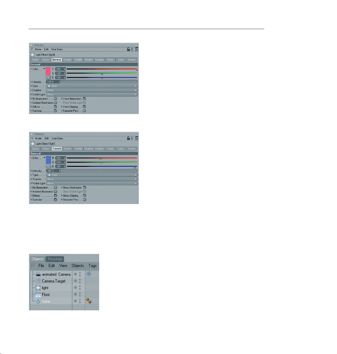
Now go to frame / time 90, set the color to a friendly blue and set a third key. Play the animation.
47CINEMA 4D R10 Quickstart – Animation
The cone metamorphosis now takes place in animated light. The color sliders change as the animation plays
and CINEMA 4D interpolates the colors between the keys that were set. Our animation is becoming more
and more interesting. That’s why we don’t want to see it from only one perspective, but we want to let a
camera fly around it.
Create a target camera (objects / scene / target camera). Rename the camera in the Object Manager to
“Animated Camera“.
Page 57

48 CINEMA 4D R10 Quickstart – Animation
A target camera differs from a normal camera in that it focuses on a specific object. This has the advantage
that the camera can be moved freely within a scene, without “losing sight“ of your targeted object. When a
target camera is created, it places with it into the scene an additional object, a Null Object named “Camera
Target“. This is the object upon which this camera is targeted by default. In this case we don’t need it because
we want to target the camera onto the cone. Delete the “Camera Target“ in the Object Manager. Click on the
cross hairs next to the camera. Now drag the cone from the Attributes Manager into the “Target Object“ field
in the “Tag Properties“ below.
In order to view the scene from the new camera’s perspective simply switch to the camera “Animated Camera“
in the editor menu under “Cameras“. The camera is looking at the scene from above but is not living up to its
name since it’s not animated – yet. We would like to animate the camera along a circular path around the scene.
For this we will need a circle. Create a circular spline (objects / spline primitive / circle). Set the radius to 1000
and the plane to “XZ“. Set the spline’s coordinates to Y=20 so the circle is above the floor and angle the spline
a little by setting the P-angle to 30 degrees.
Now we have a circle that encompasses our scene – a track for our camera. We just have to tell the camera to
follow this circle. This is done with a special CINEMA 4D tag.
Using the right mouse button, click on “Animated Camera“ in the Object Manager and select “CINEMA 4D Tags
/ Align to Spline“ from the menu that appears. A further tag will appear next to the camera.
This tag has a text field named “Spline Path“ in the Attributes Manager. Drag the circle from the Object Manager
into this tex t field.
Page 58
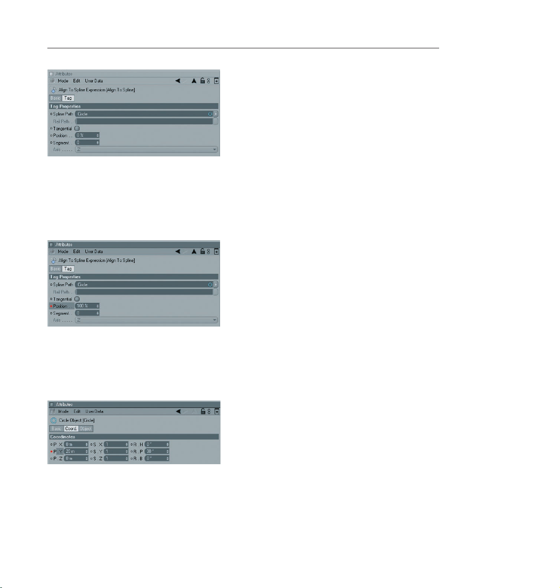
49CINEMA 4D R10 Quickstart – Animation
Now the camera is positioned on the circular path. If we play the animation, though, we will be disappointed
because the camera doesn’t move even one millimeter. That’s because we haven’t yet told it to move along
the circular path.
Make sure you set the animation back to 0 and the circle is the active object. In the Attributes Manager under
“Align to Spline“ you will see an attribute called “Position“ which is set to 0% by default. Set a key for this
attribute. Go to frame 90 and set this attribute’s value to 100%. Set another key and play the animation.
The att ri bute “P os it ion“ de te rmines how m uch of th e p at h, in %, wi ll be complete d w it hi n a
given amount of time (fram es). This means that the camera followe d 0% of the path at frame
0 and 100% of the path at frame 90. It followed the entire length of the path once.
Make sure you set the animation back to 0. In the “Coordinates“ menu of the Attributes Manager, set a key
for the Y position.
Go to frame 90. In the editor, move the circular path up along its green Y-axis until the camera has a bird’s
eye view of the cone. Key the new Y position.
Now the circular path and the camera move together on the Y-axis in the course of the animation. With just
a few animated attributes we have managed to create a complex animation.
Page 59

50 CINEMA 4D R10 Quickstart – Rendering
9. Quick Tutorial – Rendering
You’ve been a busy bee. You have created a scene, set up the lighting, animated objects and assigned materials
to them. Now we want to see the result of all this work. What you have to do is to transform this 3-dimensional
scene into a 2-dimensional image (in the case of an animation it would be an entire series of images. We will
“render“ the images. CINEMA 4D offers a wide variety of options for rendering your 3D scene. We will use a
scene from the animation chapter as our source and we will add a transparent sphere and a bright background
to the scene.
© E. Haerkoenen - eetu.harkonen@ maxinett.com
Page 60
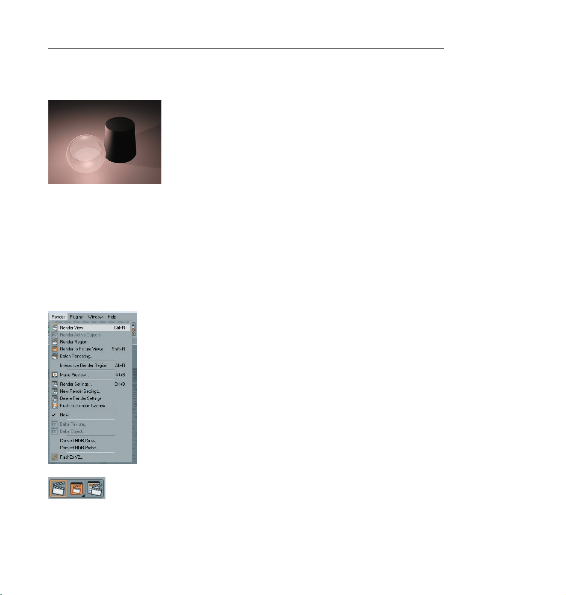
51CINEMA 4D R10 Quickstart – Rendering
Open the scene “rendering.c4d“ (file / open). Slide the time slider to frame 20 and click on “Render / Render
View“.
We will render frame 20 using CINEMA 4D’s standard settings to give you a quick impression of how our final
scene will look. This method of rendering is probably the most widely used since it can be used to make sure
the scene “is on the right path“.
Slide the time slider to frame 0 and press “Ctrl+R“ on your keyboard.
The view has been rendered again. There are three ways you can render the active view.
1. Using the main menu
2. The keyboard shortcut “Ctrl+R“
3. By clicking on the icon in the editor window
Use the method with which you feel most comfortable.
Often we don’t necessarily want to render the complete editor view but only a small part of it. This is also no
problem. Select “Render / Render Region“. The cursor will be transformed into a cross. Drag a frame around
the region you wish to render.
Page 61
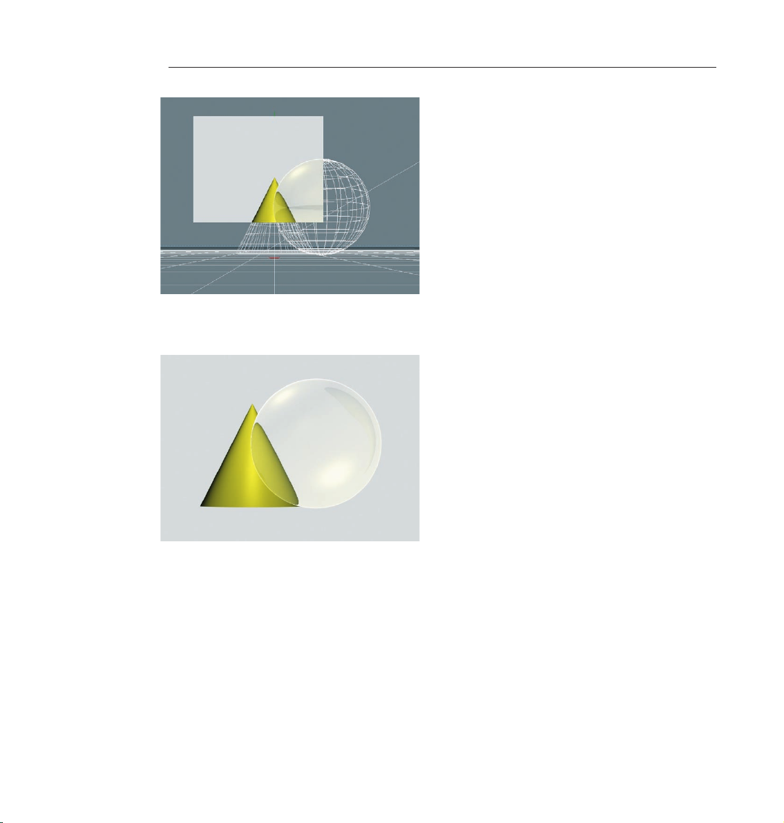
52 CINEMA 4D R10 Quickstart – Rendering
The second possibility is to render only a single object.
Select the sphere and the cone in the Object Manager. Select the command (Render / Render Active Objects).
Only the selected objects will be rendered. You can also access both commands by clicking on their respective
icons.
Rendering the editor view gives us a quick overview of the scene but it does not offer the possibility to process
this image further, to save it to the hard drive, for example. What good is the best rendering if you can’t save
the images it generates? Of course there is a command with which you can do this.
Select “Render / Render to Picture Viewer“ or press “Shift+R“. The picture viewer will open in a separate window
in which the scene will be rendered. When the image has been rendered select “File / Save Picture As“. A further
window will open. Confirm the location with “OK“. (If you are using CINEMA 4D’s demo version this function
will not be available to you).
Page 62
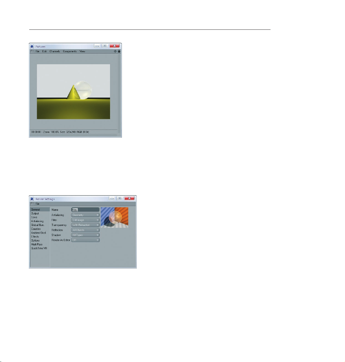
53CINEMA 4D R10 Quickstart – Rendering
No w you c an s ave any ima ge t o your har d dri ve s o you c an e dit the m in a n imag e edit ing
program or just send them to your grandma via email if you want. Rendering to the Picture Viewer has the
additional advantage that you can continue working on your scene if the image should take a while to render.
You have probably noticed that the image which is rendered to the picture viewer is very small. 320 x 240 pixels
to be exact. Why this size? And what should you do if you need a larger format? The time has come to make
use of the render settings.
Close the picture viewer and open the render settings (Render / Render Settings).
You use the render settings to determine what our final image will look like Everything from size, quality, single
image or animation can be set here. In the first menu, “General“ we can already make settings that will influence
the quality of our rendering. Take a closer look at the editor rendering of the scene. You can see the cone’s edge
behind the sphere. It looks a little pixelated. You can see a similar effect along the edge of the sphere. This is
called “anti-aliasing“. This term refers to how smoothly an edge has been rendered.
Set Anti-aliasing to “None“ in the “Render Settings“.
Page 63
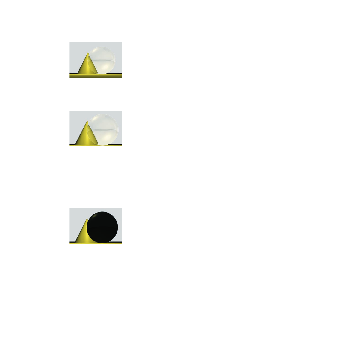
54 CINEMA 4D R10 Quickstart – Rendering
The effect is much worse without anti-aliasing. You can plainly see pixelation along the left edge of the cone
now as well.
Set anti-aliasing to “Best“ and render the scene again. All edges have been rendered sharp as a knife.
To quickly check the scene you can leave the anti-aliasing set to “None“ or “Geometry“. “None“ renders the
edges without anti-aliasing and ver y quickly. “Geometry“ renders the image with sufficient smoothing and
offers a good compromise between quality and speed. You can select the best quality when you render the
final image. You can select additional types of anti-aliasing in the “Filter“ menu. More fine-tuning is possible
in the render settings menu.
The render set tings “Transparency“, “Reflection“ and “Shadow“ can be set depending on how they are
needed. Switch the transparency to “None“ and render the scene. You will see that the sphere is no longer
transparent.
Select “Render / Delete Render Settings“. The render settings will be set back to the default settings. Switch to
“Output“ in the render settings.
This is where we will find out why the image in the picture viewer is being rendered so small. “Resolution“ lets
you choose from a wide variety of image resolutions. You can also simply enter the desired image size. Slide
the time slider back and forth until you find a frame you would like to render. Set the size to “800 x 600“ and
render the image in the picture viewer.
Page 64

55CINEMA 4D R10 Quickstart – Rendering
Now you can see a lot more of the scene. We’ve done enough with single images and want to move on to an
animated scene. We want to set everything in motion. Set the render size back to “320 x 240“ and “Frame“ to
“All Frames“.
CINEMA 4D will now render all of the scene’s pictures. The scene’s length is determined in the preferences
(Edit / Preferences) menu. Our scene runs from frames 0 to 90. We just have to determine which file format our
images will have and where they will be saved.
Switch to “Save“ in the render settings, click on “Path“ and choose a name and a place to save your film. Now
choose a format – you can use “Quicktime“ or “AVI“.
Page 65

56 CINEMA 4D R10 Quickstart – Rendering
You can als o ch oo se singl e imag e format s such as TIFF, for example. CINEM A 4D will the n save
90 images for this particular animation. You can then create a film from these single images using editing
software. Some formats even allow you to save an alpha channel with the image. Alpha channels help you to
cut out objects in the image in an image editing program, letting you change the background, for instance.
Select “Render / Render in Picture Viewer“ and watch CINEMA 4D work.
In the “Options“ menu of the render settings you will find further settings that influence your rendering. Here
you can turn textures off, generate a protocol as a text file and regulate the level of detail.
If all you need is a quick preview of your animation you can save yourself the trouble of always opening and
changing the render settings by selecting the preview function (Render / Make a Preview). The settings used
here are kept to a minimum.
Page 66

57CINEMA 4D R10 Quickstart – Multi-Pass-Rendering
Of cour se t he “ Out p ut“ and “Sav e“ s ettin gs d epen d on the req uire m ent s of you r sc ene.
If you render a single image that will be printed with a resolution of 300dpi on a 8.5x11 size page you should
render the image with a resolution of at least 2550 x 3300. If you want to print the image in a picture size of
3x5, a render resolution of 1000 x 1500 will be more than enough. By the way, there are many services that will
print your digital images. Maybe you can send us your first CINEMA 4D work of art as a Holiday card!
Animation is a different story. The frame rate, which is also editable in the “Output“ menu of the render settings,
plays an important role in animation. The frame rate is the speed at which the animation plays. A frame rate of
25 means that 25 images per second will be played. If you produce an animation for the European market you
will have to adhere to the PAL standard which uses an output size of 768 x 576 pixels and a frame rate of 25. If
you produce a film the frame rate must be set to 24 and a much higher resolution that for television.
10. Quick Tutorial – Multi-Pass Rendering
As you have read in the previous chapter rendering can take up a lot of time. The last thing you want to have to
do is render a long animation a second time because you accidentally set a wrong property. Let’s say you look
at your film again the next day and realize the specular light on the sphere was set much too bright. Or worse,
you’re a 3D professional and a client is looking over your shoulder telling you he would rather have the pink
panther dove blue! Now you have to create a new texture for the character and render the entire animation
again – unless you had secretly activated Multi-Pass rendering. With the help of Multi-Pass rendering you can
place 3D objects in front of a real background (keyword: compositing) or you can use filters in post-production
to make the images more attractive. In this chapter we will show you how to use Multi-Pass rendering so we
can take away the hassle of clients who want you to make unexpected changes to a project ASAP.
Open the file “Multi-Pass_e.c4d“. The time slider is set to frame 15. We want to render this frame and
subsequently make changes to it using an image editing software. Open the render settings (Render / Render
Settings) and select Multi-Pass.
Multi-Pass rendering means that not only the actual image will be saved but also the individual channels (passes)
which comprise such an image. A channel can, for example, contain an image’s environment light, specular
light, transparency or even single objects. This information is output as a separate image. These images can be
edited individually using an image editing software and brought together to a single image after editing. In
the top right corner of the Multi-Pass settings there is a menu which you can call up by clicking on the arrow
which shows all renderable channels.
Page 67

58 CINEMA 4D R10 Quickstart – Multi-Pass-Rendering
Set the format to “JPG“ and click on the “Path“ button. Find a place to save the image on your hard drive and
name the image “Multi-Pass_Scene“. (In case you are working with a demo version you will find the result of
this function in the following files: “scene_diffuse0015.jpg“, “scene_specular0015.jpg“, “scene_trans0015.jpg“
and “scene_refl0015.jpg“. Add the channels “Diffuse“, “Reflection“, “Specular“ and “Refraction“ and render
the scene using the command “Render / Render To Picture Viewer“.
Page 68

59CINEMA 4D R10 Quickstart – Multi-Pass-Rendering
You will not notice anything special when the image is rendered. When you look into the “channel“ menu of
the image viewer you will see that you can call up each of the channels you just rendered individually. If you
now look on your hard drive where you saved the image you will see four files. Since “Layer Name as Suffix“
was activated in the Multi-Pass window each image was given a name according to its channel: “Diffuse” for
the diffuse lighting, “refl“ for the reflection, “specular“ for the specular light and “trans“ for the transparency /
refraction, each with the frame number. If you take a look at each image you will see that only the information
from the individual channel is contained in the respective image. In the “trans“ image only the sphere can be
seen since it is the only transparent object in the scene.
But how can we use these images to manipulate our scene after it’s been rendered? By using an image editing
software such as Photoshop. Photoshop is a very popular program which has established itself as the standard
image editing software. If you don’t own a version of Photoshop you can download a demo version from their web
site at www.adobe.com. Photoshop can split an image into several layers. These layers can be mixed in various
ways but it would be a lot of work if we had to open each of our images in Photoshop and mix them manually.
CINEMA 4D makes it possible for you to integrate all layers into one file. This function does not work for every
file format, such as JPEG for example. Since we want to work with Photoshop it makes sense that we use
Photoshop’s own format “PSD“ (Photoshop Document).
Set the format to “Photoshop (PSD)“ in the Multi-Pass window. If you have Photoshop 7.0 or newer, activate
the checkbox under “Options“ at the bottom right of the window. Render the image.
“Multi Layer File“ is automatically activated in the Multi-Pass window as soon as we select PSD as our format.
This simply means that all four images will be contained in one image file as separate layers. Convince yourself:
On your hard drive you will see a file named “Multi-Pass_scene0015.psd“. Users of the demo version will find
this file alongside with the Quickstart PDF-document. Open the file in Photoshop. The image you just opened
looks like the rendered image in CINEMA 4D. Take a look at Photoshop’s layer palette and you will see our
channels, properly named and linked with each other.
Page 69

60 CINEMA 4D R10 Quickstart – Multi-Pass-Rendering
The great thing is that we can change the layers in Photoshop and at the same time the channels of our
rendering. Remember the specular light we mentioned at the beginning of the chapter? We think it can be a
little brighter.
Select the “Specular“ layer in Photoshop and call up the “Levels“ function (Image / Adjustments / Levels).
Now you’ve already made the specular light brighter without having to render the image again.
You may have noticed that there was a shadow in the original scene that is not visible in the Photoshop file.
This is because the shadow has its own channel and we simply did not activate it in the Multi-Pass rendering
menu.
Add this channel in CINEMA 4D, render the image and open it in Photoshop. (For the users of our demo
version: The result reflects what you see in “Multi-PassShadow_Scene0015.psd“). Now the shadow has its own
Photoshop layer. The shadow is very dark and the right edge of the cone can barely be seen. We want to change
that now. Select the shadow layer in Photoshop and set its “Opacity“ to 50%.
Page 70

61CINEMA 4D R10 Quickstart – Multi-Pass-Rendering
The image already looks brighter. And what should we do with the client who wants his pink panther dove blue?
Aside from the fact that our scene contains neither the color pink nor a panther, what should we do when we
want to change the color of the cone only? How do we change the color of a single object in the scene? For
this we have to prepare a little in CINEMA 4D first.
Assign a compositing tag to the sphere in CINEMA 4D’s Object Manager under “CINEMA 4D tags / compositing”.
Switch to the “Object Buffer“ menu of the Attributes Manager and activate “Buffer 1“.
The compositing tag makes it possible to assign an image buffer to one or more objects in the scene. Assign a
compositing tag to the cone as well. Activate the second buffer.
Page 71

62 CINEMA 4D R10 Quickstart – Multi-Pass-Rendering
The sphere and cone are now in two separate image buffers, 1 and 2. Now we have to activate these buffers
in the render settings.
Add 2 “Object Buffers“ in the Multi-Pass settings window. For the first, set the “ID“ to “1“ and for the second
to “2“. Render the scene and open the new file in Photoshop.
At first glance nothing has changed in the Photoshop file. There are still only five layers. Where are the new
objects? They can be found in the channel palette. An “Alpha Channel“ was created for each object. An alpha
channel is a gray scale image used to cut out objects in the image.
Select the “Refraction“ layer in Photoshop. Choose select / load selection. Set “Channel“ to “Object Buffer 1“.
We just loaded the buffer channel as the selection. Various image editing options will now be limited to the
area within this selection – the sphere.
Call up “image / adjustments / hue / saturation. Click on “Colorize“ and set the “Hue“ to 240 and the saturation
to 100.
Page 72

63CINEMA 4D R10 Quickstart – XPresso
Only the sphere will be colored. Since it consists mainly of refractions, we chose the respective layer in
advance.
Mult i-Pass reall y co mes to shi ne w hen it’s u sed with ani mated sce nes. W ha t P hotosho p d oes
for sin gl e image s, composi ti ng programs d o f or animations. Af ter Ef fec t s a nd Combust ion are
tw o of the se programs. Edit in g s oft ware such as F in al Cut let s you e di t i ma ge layer s a s w ell.
CINEMA 4D works with all of these programs, partly over special export plugins which offer an extensive
number of settings. You can change a color in a 15-minute animation in seconds.
11. Quick Tutorial – XPresso
Expressions let you set dependencies for object properties. In other words, you can use rules to automate
a scene: “When object A performs action B object C should perform action D.“ So you don’t have to enter
these expressions manually MAXON created XPresso. XPresso is a graphic interface which puts an end to the
cumbersome act of typing code. XPresso lets you create expressions using drag & drop which is simple (and
can even be fun) and offers enough functionality to be able to solve just about any problem. We will now take
a look at what this problem solving looks like. In this tutorial we will build a kind of telescopic arm.
Open a new scene. Create three cylinders (objects / primitives / cylinder). Rename them into “cylinder_small”,
“cylinder_medium” and “cylinder_big”. In the Attributes Manager set the radius of “cylinder_medium” to 45,
the radius of “cylinder_small” should be 40.
Page 73
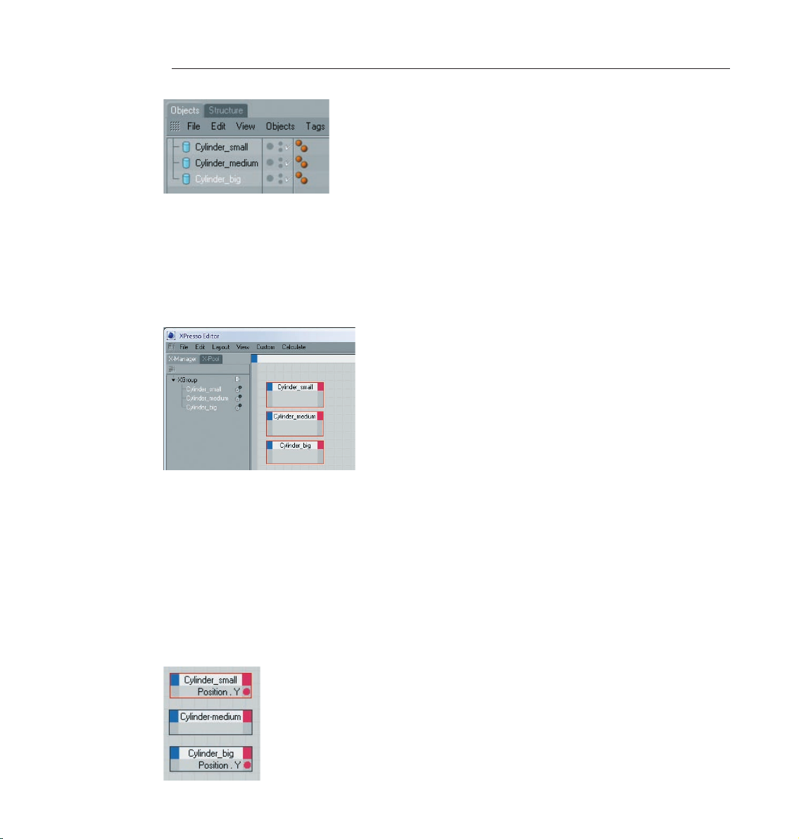
64 CINEMA 4D R10 Quickstart – XPresso
We now have three cylinders with different radii in the scene. Our goal will be a telescopic effect by pulling
the smallest cylinder up while keeping the medium cylinder dead center as it moves with the smallest cylinder.
This is a case for XPresso!
Apply a new XPresso tag. The quickest way to do this is to click on one of the cylinders in the Object Manager
with your right mouse button. Select CINEMA 4D Tags / XPresso. By the way, it doesn’t matter which object
you apply the tag to. The XPresso editor will open. Drag all three cylinders from the Object Manager onto the
empty surface of the XPresso editor. The objects will be transformed into little boxes, so-called “Nodes“.
Nodes are XPresso’s cornerstones. They represent objects or functions. Nodes have an input and an output
which allow them to exchange information with other nodes. You can view a node’s complete input by clicking
on the little blue box in the top left corner of the node. A node’s output can be viewed by clicking on the red
box. Take a look at the exits of the cylinder’s nodes. Some of them will surely be familiar to you (Attributes
Manager).
Think about what it is we want to happen. We want to pull the small cylinder up, i.e.; change a Y-value. This
movement should in turn influence the Y-value of the medium cylinder which should stay exactly in the center
of the Y-positions of the big and small cylinders. We can say that we want to set the medium cylinder to an
average value of the other two cylinders.
Click on “Cylinder_big’s“ red corner and select Coordinates / Position / Position Y. Do the same for “Cylinder_
small“.
Page 74
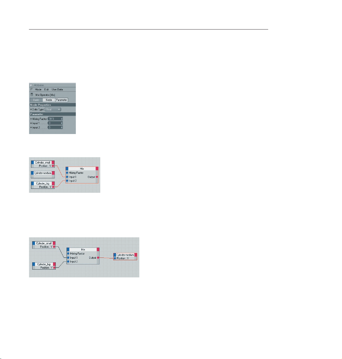
65CINEMA 4D R10 Quickstart – XPresso
Both cylinders can now pass on their respective Y-position. We will use a special node to calculate the average
between these two points.
Switch to the X-Pool tab and drag a “Mix Operator“ node from System Operators / XPresso /
Calculate / Mix onto the surface where the other nodes are. Set the “Mix“ node’s “Mixing Factor”
to 50% in the Attributes Manager.
Connect the “Cylinder_small“ “Position.Y“ output to the “Mix“ node’s input 1 and the “Cylinder_big“ exit to
the “Mix“ node’s input 2.
Both Y-positions will now be transmitted to the “Mix“ node which will now calculate their average of their
respective values. The 50% setting makes sure the values will be mixed evenly. The result will be the Y-position
of the medium cylinder.
Click on the blue corner of the “Cylinder_medium“ node and open an input for the Y-position (Coordinates /
Position / Position.Y). Connect the “Mix“ node’s output with the input of “Cylinder_medium“ node.
Now gaze in amazement at the result in the editor window. Move the small cylinder along its green Y-axis. The
center cylinder aligns itself automatically.
Page 75

66 CINEMA 4D R10 Quickstart – XPresso
We still have one problem: you can still drag the cylinder so far that our telescope comes apart. It would be nice
if we could restrict the movement a little. Needless to say XPresso also has a solution for this!
Go back to X-Pool and drag a “Clamp“ node into the XPresso editor. Set its “Max“ value to 300 in the Attributes
Manager.
The “Clamp“ node restricts various properties that are transferred to its “Value“ input to a range between 0
and 300. Now we just have to connect the node to the rest of the setup.
Click o n t h e blue co r n e r o f t h e “Cylin d e r _ s m a l l “ n o de and o p e n a n i nput for t h e
Y-position (Coordinates / Position / Position.Y). Drag “Cylinder_small“ from the Object Manager into the XPresso
editor again and open an output for the Y-position. Connect this output to the “Value“ input of the “Clamp“
node. Connect the output of the “Clamp“ node to the “Position.Y“ input of the “old“ “Cylinder_small“ node.
Page 76
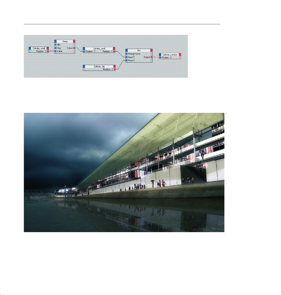
Now the cylinders can only be moved a limited distance in the Y-direction, just like a real telescope.
12. Tips and Tricks
67CINEMA 4D R10 Quickstart – XPresso
CINEMA 4D has been able to build a large community of users around it who are more than happy to help
newcomers in any way possible, be it through the use of home-made tutorials, directly in one of the many
forums or by offering free models, plugins, expressions or textures.
One of the main sources of information, of course, is the MAXON web site www.maxon.net.
Page 77

68 CINEMA 4D R10 Quickstart – XPresso
Here you will find news, interesting projects that were done with CINEMA 4D, an extensive CINEMA 4D link
library and even a form for questions for our suppor t department. You can even get information about third
party seminars and training.
The Plugin Cafe is a sister site to the MAXON web site www.plugincafe.com.
If you’ve pushed your skills to the limit or if you are looking for a specific tool you can probably find what you
need at this site. You will find an extensive collection of plugins, expressions, interfaces and BodyPaint 3D
brushes, many of them free. There is even access to CINEMA 4D’s Software Development Kit (SDK) for those
who would like to program their own plugins. The SDK documents how CINEMA 4D works and how you can
expand it.
A large selection of books is also available for those who would like to expand their CINEMA 4D library. There
are books from the basics to specialization such as character animation. Just enter the keyword CINEMA 4D
into the search engine of your favorite online book store.
Flipping through books which don’t have anything to do with computer graphics can also be helpful. 3D is
a complex field in which many of the classic arts and techniques are combined. Books about photography,
lighting, direction, acting, image creation and painting should be part of every serious 3D artist’s library.
In addition, you will find a wealth of information on all of these topics online.
Eadweard Muybridge’s photo books are especially good for character animators. Muybridge was known for
his photographic depiction of human and animal motion.
These Muybridge photos are a must if you’re studying character animation. An online search for his name will
be worth the effort.
3D models are being offered online in all quality and price classes. Two well-known sources are “TurboSquid“
and “ModelBank“. Both websites offer access to the CINEMA 4D object database. You will find more than just
models here - textures, plugins and even motion capture files that can be imported into CINEMA 4D via the fbx
format. Commercial sites also offer a wealth of content.
If you’re looking for advice and don’t want to test the MAXON support just yet you can find help quickly in
the CINEMA 4D forums. These are independent discussion forums in which users can meet to help each
other with problems or to “just talk 3D“. Here you won’t have to wait long for an answer. Since many topics
have been discussed here already it’s advisable to search the archives first. Chances are you will find the
solution to your problem in the archives. The C4D forum is a part of the “C4D meet“, a so-called portal site
that offers information about CINEMA 4D around the clock. These portal sites are perfect place to rummage
for information. A couple of large English language portal sites that deal with 3D and CINEMA 4D are CGTalk
(www.cgtalk.com) the PostForum (www.postforum.com) or Renderosity (www.renderosity.com). Here you
can find out what’s going on in the “3D scene“.
Another English language portal site with extensive information about animation is the “Animation World
Network“ (www.awn.com). Here you will find anything and everything that has to do with classic and computer
animation.
Since the internet is always changing, doing a search for “CINEMA 4D“ in various search engines (such as
“Google“, www.google.com) would be a good idea.
Google is also a good source for finding models. Through its special image search function you can find photos
or drawings of practically any object. Corbis (ww w.corbis.com) can also be a good source of ideas.
Page 78

69CINEMA 4D R10 Quickstart – XPresso
Even mail order catalogues can be a great source of information on how an object is supposed to look.
Textures are all over the internet as well. Taking your camera and photographing textures yourself is even better.
Inspiration is everywhere. You can build your own texture archives in no time.
Try to get away from the technical point of view. Learning a software is only a matter of time. A good 3D artist
has the ability to use software as a tool that helps him realize his ideas. The real creativity lies with the idea,
not the software. So when you create your next scene don’t worry so much about creating the perfect object.
Concentrate rather on how you can make a harmonious composition with this object with a fitting theme
and proper lighting. Also, think about the message you are trying to send to the viewer. The same goes for
animators. A technically perfect animation is a great achievement but it will put your audience to sleep if the
concept is bad. It’s not so bad, on the other hand, if your animation is a little bumpy and imperfect but your
story touches the viewer.
We hope this manual has helped you to master the technical part of 3D graphics. What you do with what you’ve
learned is in your hands.
Page 79

70 CINEMA 4D R10 Quickstart – BodyPaint 3D
Welcome to BodyPaint 3D
This is the BodyPaint 3D tutorial. In this tutorial we will explain the most important functions in order to give
you a running start in the world of “body painting“. Even if BodyPaint 3D appears to be difficult at first, you will
soon notice how intuitive BodyPaint 3D really is. In this tutorial we have also put an emphasis on a fast learning
curve and a high degree of user friendliness for this module. Let’s start with its structure.
© Peter H ofmann w ww.pe xel.de pe xel@3dup.com
1. Introduction
BodyPaint 3D will revolutionize the way you work with textures in such a way you will wonder how you ever
got along without it! With this module you can paint your models as they are: in 3D. This is what BodyPaint 3D,
the revolutionary way to texture objects, is all about. In addition, BodyPaint 3D lets you paint in several texture
channels at once, and thanks to RayBrush even directly on the rendered image itself. Projection Painting is a
tool we have integrated that makes it possible to paint on complex objects without distortion.
Page 80

71CINEMA 4D R10 Quickstart – BodyPaint 3D
Using the UV-tools you can relax and stretch your UV-mesh, no matter how complex it is. Put simply, a UVmesh is a second impression of a polygon mesh that projects the texture onto a polygon object. The days of
2D texturing are over and you can finally concentrate on what’s important in texturing: creativity. Everything
that took up so much time with 2D texturing is now done by BodyPaint 3D and you can deliver your projects
faster. Let’s move to the user interface.
2. General Information / Interface
First take a look at the screenshot on the next page.
Here you see one of the two standard layouts: “BP UV Edit“. The second layout (“BP 3D Paint“) is set up in a
similar fashion, only without the UV-mesh editor window which gives you more room in the editor window
to paint.
Page 81

72 CINEMA 4D R10 Quickstart – BodyPaint 3D
1. Editor Window (RayBrush Window) Here you can see the object you will be painting. You can rotate, move
and zoom the window as needed. The RayBrush mode lets you paint directly onto the object in the rendered
version of the view. This gives you control over the amount of color applied and can see right away how a new
color looks on the object.
2. Texture Window (UV-mesh Editor Window)
This is where you edit your UV-mesh. You can relax and restore your UV-mesh. If you use the UV-Manager’s
UV-tools you can watch how the texture relaxes. You can also watch the color application process in this
window, which will then be visible in the editor window right away.
3. Active Tool / Attributes Window including UV-Manager
Here you can switch between tabs to make the properties of the different types of brushes and the UV-tools
of the UV-Manager visible. The UV-Manager lets you restore the UV-mesh using an algorithm. It recognizes
layered polygons and attempts to relax the UV-mesh for optimal placement over the entire surface and, if
necessary, new placement. All remaining “relaxation“ can be adjusted manually.
4. Object Manager
We’re sure we don’t have to say much about the Object Manager. It’s the same manager as in the CINEMA
4D main program and lets you select the object to be edited or change its position in the hierarchy.
5. Material Manager
This is the same manager as the CINEMA 4D manager with expanded functionality. This is where you will
find your textures with their respective layers. If needed, you can paint in several layers at once (for example
color and relief channels). To do this simply select the texture to be painted and the respective layer and start
painting.
6. Command Palette
The command palette contains the paint assistant, the Projection Painting and many other tools (that you’re
probably used to using with 2D paint programs). The wizard eliminates the need to manually create a
texture including the UV-mesh. It also calculates the texture size and channels. Without these bothersome
preparations you can begin painting right away.
Page 82

73CINEMA 4D R10 Quickstart – BodyPaint 3D
3. Sample Images
We’ve reached a part of the tutorial for which words are not necessarily needed. Simply take a look at the
following images.
Page 83

74 CINEMA 4D R10 Quickstart – BodyPaint 3D
4. Quick Tutorial – the Wizard
The wizard takes a lot of preparatory work off your hands and lets you begin texturing / painting in seconds.
Before we actually start painting the object we would like to show you how quickly you can start painting, just
in a few steps.
Create a cone primitive (objects / primitive / cone). Switch to the predefined standard layout “BP 3D Paint“.
Click on the “Paint Setup Wizard“ icon
and select the “Next“ button twice, the “Finish“ button once and to exit the assistant click on “Close“. At the
left of the command palette select the “Brush Tool for Painting Textures“
and drag the cursor over the cone while pressing the left mouse button. Voila!
Page 84

75CINEMA 4D R10 Quickstart – BodyPaint 3D
Aside from the fact that you will never have a need for a cone with a white mark on it, this simply demonstrates
how BodyPaint 3D works.
Now we’ll get to the heart of this tutorial. Open the file Claude_BP_start.c4d. Say hello to Claude, our guinea
pig for the day. In the course of this tutorial we will alter the color of his right eyelid a little and apply a bump
layer in elephant-look to his skin.
Select the predefined standard layout “BP UV Edit“ at the top and to the left of CINEMA 4D’s main editor
window. Click on the Paint Setup Wizard Icon so we can make the necessary preparations to the texture.
Click on “Deselect All“ in the window you just opened and apply a white check mark to the “eyelid right“
object only.
We have just determined that a texture should be created only for the right eyelid object. Click on “Next“. Leave
the settings in the next window the way they are. The selection “Single Material Mode“ would create a texture
for each object individually. If the box is not checked all objects will share one texture surface. Click on “Next“
again. In the next window check the bump channel. The color channel is selected by default. You can double
click the little gray boxes next to each texture channel and assign each channel a base color. Since Claude likes
elephant gray we will leave the boxes the way they are. Leave the rest of the settings the way they are and click
on “Finish“, then on “Close“ in the next window. The basic textures have been created and we can start painting.
If you have experience with earlier texturing methods and the time it took to even get started BodyPaint 3D
will seem like a blessing to you. BodyPaint 3D saves you a lot of time. Now let’s move to the second part of the
tutorial: the UV-meshes and the first brush stroke.
Page 85

76 CINEMA 4D R10 Quickstart – BodyPaint 3D
5. Quick Tutorial – First Painting Lesson
At the bottom left of the Material Manager you will find the texture we just created, right next to “Mat“
This is the de fault n am e for a new texture. Of course you can rename the texture if y ou like.
The fir st material is the color layer and the se cond is the bump layer (at the top of the window
you w il l s ee the abbr eviations wh ic h r efer to the se laye rs – “C“ for colo r a nd “B“ for bump).
Now Select the “Use UV Polygon Edit Tool” symbol.
Once you have selected the corresponding texture in the color channel the UV-mesh should become visible in
the texture window at the upper right. If the mesh is not visible, activate it by clicking on “UV Mesh / Show UV
Mesh“ in the texture window menu. Luck is on our side! The UV-mesh looks good. The only thing that bothers
us is the fact that the edges of the eyelids are too small (highlighted in orange in the next image!).
Page 86

77CINEMA 4D R10 Quickstart – BodyPaint 3D
The individual UV-mesh polygons of these eyelid edges take up less texture area than the rest of the polygons.
That’s why a texture placed into the bump channel appears larger in these places (photograph of elephant skin,
for example). We can do without this, though, since we are painting our own skin structures onto the surfaces
and not using an existing texture. We can counter any distortion we encounter when painting manually by using
“Projection Painting“. The stroke will maintain its width no matter how the polygon is spread over the mesh.
Move and zoom the editor window view until Claud’s right eyelid fills the view.
Page 87

78 CINEMA 4D R10 Quickstart – BodyPaint 3D
Select the brush on the command palette on the left, Now select “Brush Tool for Painting Textures” for applying
the color. Set the size to 25 and the hardness to 40 in the brush’s Attributes Manager.
and select a pink color using the “Preview Active Channel” directly below. Use the sliders that appear on the
right.
If necessary, increase the HyperNURBS subdivision. Activate the “Render Active View for RayBrush Painting“
on the command palette.
(This will render the view and makes it possible for you to control the color application and the look of the
strokes for the final rendering). Activate the “Enable / Disable Projection Painting“
(You already know what this function does) and start painting. Of course BodyPaint 3D suppor ts the use of
graphic tablets such as a WACOM Intuous. Painting objects with a pressure sensitive pen on a graphic tablet is
much easier than painting with a mouse.
Page 88

79CINEMA 4D R10 Quickstart – BodyPaint 3D
Paint along the edge of the eyelid. The eyelid will probably end up looking like this:
If you move / rotate the figure now or click on the “Apply the Content of Projection Paint Plane“
you will see how the color was applied to the texture (you can see the recently applied strokes of color in the
window to the right).
You can take the same steps for the bump layer. We will take you one step further, though, in order to be able
to explain an important function. We will paint both eyelids at the same time!
Select the texture in the color channel of the Material Manager. Now click on the icon with the black/orange
pencil at the left of the Material Manager. A light gray background tells you the multi-brush mode is active.
Select the pencil icon next to the “B“ of the bump channel as well.
Page 89

80 CINEMA 4D R10 Quickstart – BodyPaint 3D
You have now told BodyPaint 3D that you want to paint in both layers at the same time. If you like you can
switch from the standard “BP UV Edit“ layout to the “BP 3D Paint“ layout. This gives you more room to work
in the editor window.
Rotate the view so you can see the eyelid from the top. Activate the “Render Active View for RayBrush Painting“
and the “Enable / Disable Projection Painting“ mode and set the brush size to 10 and hardness to 40. Switch
to the color layer’s “Color” menu and set the color to a medium gray which will be the base color for our
eyelid. Now go to the bump layer’s color preview and set the color to black. When you paint on the object
you will notice that both colors are being applied to the object – the gray base color and the black (to indicate
indentations). (If white were the color of the relief channel it would “raise” the brush stroke instead of indicating
indentations). The result could look like the following image.
Load the Claude_BP_final.c4d file and take a look at it when you have time. Here are some everyday tips with
which you can achieve great results quickly and easily.
6. Tips and Tricks
A very helpful function can be found in CINEMA 4D’s preferences (Ctrl+E). In the “BodyPaint“ menu you will
find the function “Project On Invisible Parts“. Which, when activated, can make your work a lot easier. Let’s
assume you want to color the arm of a figure or sprinkle color on the entire figure. You would have to apply
the color with this function deactivated, rotate the arm, apply the color, rotate the arm and, well, you get the
idea. When this function is activated you apply the color in the front view and the color is applied to all surfaces
lying behind this surface at the same time. Just make sure you don’t apply color to objects you don’t want to
color when this function has been activated.
If a texture map does not fit correctly at the point where large and small polygons meet (in the case of low-poly
objects that are subordinates of HyperNURBS) set the function “Tile UV’s“ from “User” to “Border“ or “Edge”.
This sends the UV-mesh through the HyperNURBS algorithm and subdivides it to fit the polygon object.
Avoid UV-mesh polygons that meet to a point when applying a “noise texture“ to a bump layer. The narrower
a 3-sided polygon becomes, the coarser the bump noise channel will be rendered. Of course such a polygon
has much less area for the noise structure at its tip than it does at its center which results in a magnification
effect of the noise structure. Try to set up each side of a triangulated polygon as an isosceles. This also goes
for “4-point polygons“ when they converge into a trapezoid. The more square the polygon the more even the
structure will be.
Page 90
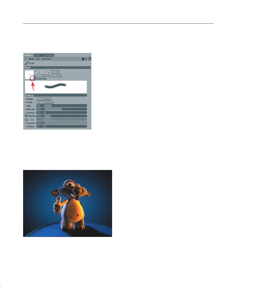
81CINEMA 4D R10 Quickstart – BodyPaint 3D
It goes without saying that you need different brushes for different texture looks. CINEMA 4D has a wide
variety of brush types for you to use. Just select the tab “Attributes“ and click on the small arrow on the brush
preview
Here you will find all the brushes your heart desires. If you don’t find the brush you’re looking for we’ve beat
Murphy to the punch and have given you the possibility to create and save your own brushes. Just make the
changes you want and click on the “Add Preset“ button.
With this tutorial you have gotten to know how BodyPaint 3D works and you can convince yourself of the
advantages painting directly onto objects themselves offers. With only a little practice you can also achieve
similar results as you can see on the next image – Claude’s new texture outfit.
Here the same rule applies for best results: try it, don’t just study it!
Page 91

82 CINEMA 4D R10 Quickstart – Advanced Render
Welcome to Advanced Render
(Optional module)
This is the Quickstart Tutorial for the Advanced Render Module. It will show you many of the module’s typical
applications and covers some theoretical physics behind the effects.
© Jürgen Schulz, schulz@formmad.com
1. Introduction
The Advanced Render Module expands the realm of possibilities of CINEMA 4D’s renderer with several
fascinating functions. Users who want to make photorealistic renderings will find these functions especially
interesting. The module integrates itself seamlessly into existing rendering settings which makes learning to
use it a simple matter. The module adds the following functions to the standard renderer: Global Illumination
(a rendering method for especially realistic lighting), caustics (achieves lighting effects on mirrored and
transparent materials), depth of field, specular lighting, glows and sub-poly displacement.
Page 92
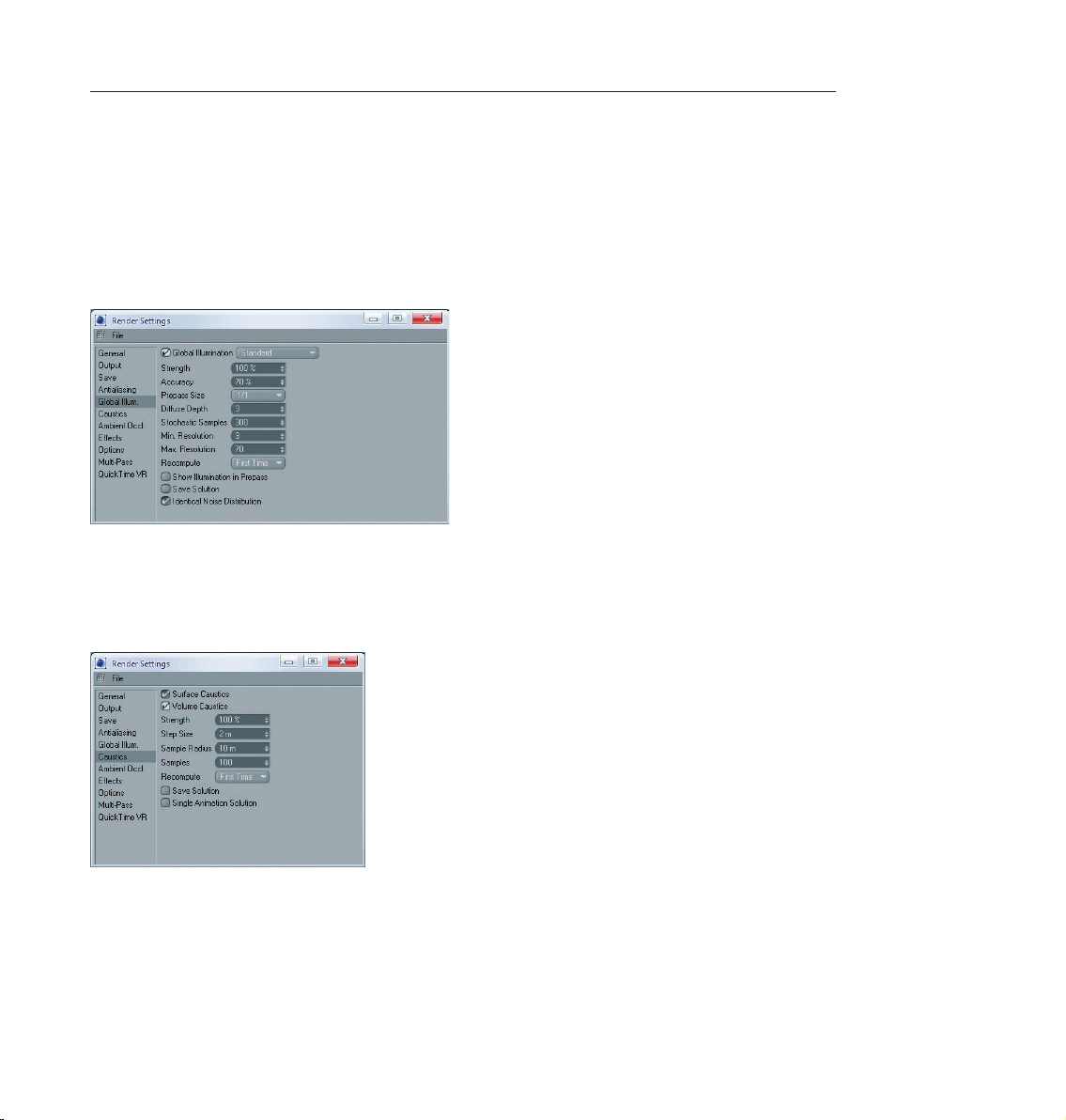
83CINEMA 4D R10 Quickstart – Advanced Render
2. General Information / Interface
As soon as you have installed Advanced Render you will notice several new options in your render settings
(Render / Render Settings). Under “Global Illumination“ you can activate “Global Illumination Rendering“. As
soon as you have activated “Global Illumination Rendering”, other options will be made active which allow you
to create custom settings for radiosity. A material’s “luminance“ channel is closely associated with this field.
These settings let you determine if a particular material should be rendered with Global Illumination . Further
settings can be applied to individual objects using the “compositing tag“.
Caustics acts in a similar fashion. The global settings can be found under “render settings“. Here you can
activate or deactivate surface and volume caustics separately. Options relating to specific materials can be set
in the luminance channel. In addition, caustics also offers a third setting. You will find this in the light object.
The use of caustics requires at least one light object. Within a light’s caustics menu it is possible to determine
whether the light source should generate surface or volume caustics.
“Depth of field“, “highlight“ and “glow“ are so-called post effects. You will find them in the render settings
under “effects“. Further settings for “depth of field“ can be made in each camera’s attribute settings. A post
effect will first be calculated after an image has been completely rendered. You can imagine it as a layer which
is placed on top of the image after it has been rendered.
Page 93
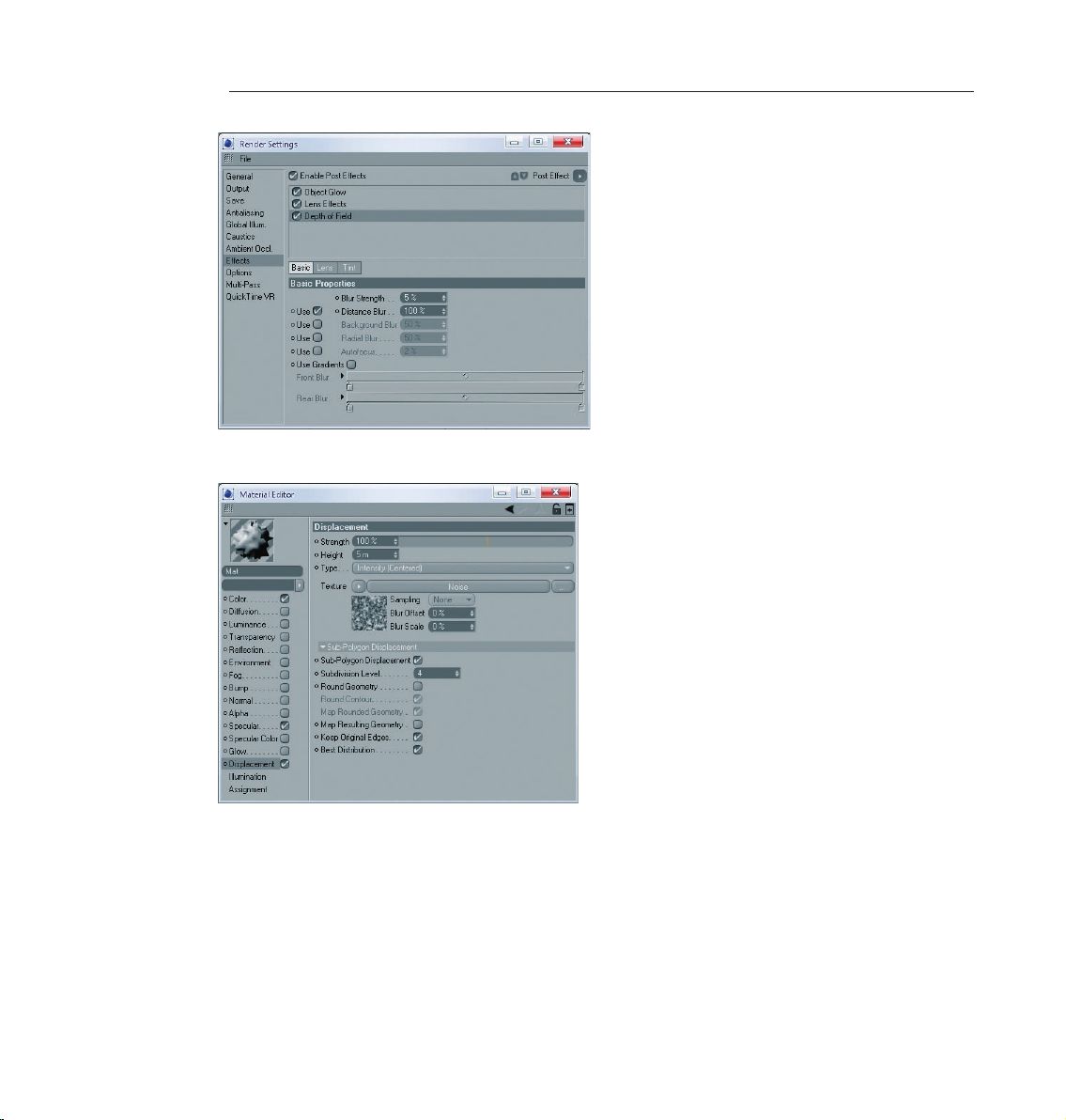
84 CINEMA 4D R10 Quickstart – Advanced Render
The Sub-Polygon Displacement can be activated in a material’s “displacement“ channel.
Page 94

3. Sample Images
Here you can see what’s possible with the Advanced Render functions.
85CINEMA 4D R10 Quickstart – Advanced Render
Page 95
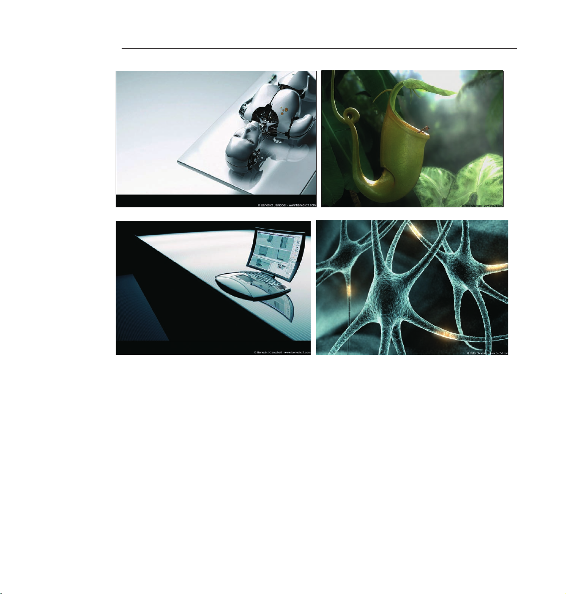
86 CINEMA 4D R10 Quickstart – Advanced Render
Page 96

87CINEMA 4D R10 Quickstart – Advanced Render
4. Quick Tutorial – Global Illumination
Light as we know it in the “real“ world spreads on its own. It is reflected by the objects it hits. This differs
depending on an object’s surface characteristics. Imagine a room with a window on one wall. Light is being
cast through the window onto the floor of the room. The light doesn’t stop there, but is reflected from the floor
onto other objects which, in turn, reflect the light themselves. The room is lit by “diffused“ (indirect) light.
The raytracing procedure takes into account diffused light. For example, if only one light is used, everything
lying in the shadows will not be visible. Maybe you have already built a virtual room into which a light source
is shining through a hole in the wall. The light in the virtual world hits an object, lights it – and that’s it. The
light spreads no further. Global Illumination rendering is different. Global Illumination rendering lets every
object within the scene act as a light source. As you will see, you can actually light a Global Illumination scene
without using a single light!
Op e n a new (e m pty) fil e. Crea te a sk y ob ject (obj ects / scene / sk y) and a f loor ob ject
(objects / scene / floor). The sky object encompasses the entire scene like a large sphere. The floor surface is
an infinite sur face.
Create a torus (objects / primitive / torus) and move it to a y-position of 100, slightly above the floor.
Now we will light the scene with diffused light using Global Illumination rendering. We will use our sky object
as the light source.
Switch to the Material Manager. Create a new material (file / new material). Switch to “basic“ in the Attributes
Manager. Deactivate “color“ and “specular“ and activate “luminance“. Drag the material from the Material
Manager onto the sky object in the Object Manager.
Create another material and give it your favorite color. Drag this color onto the torus.
Page 97

88 CINEMA 4D R10 Quickstart – Advanced Render
The luminance channel turns the material into a light source. Since the sky object spherically encloses the entire
scene. It acts as a huge lamp which lights the torus from all sides. This effect will only be visible when we use
Global Illumination as the render mode.
Open the render settings (render / render settings). Switch to Global Illumination and activate Global Illumination.
Switch to the options menu and make sure that “Auto Light“ is deactivated.
Rotate the scene in the editor viewport so the camera is at such an angle as to show only the floor in the
background. This speeds up rendering since the rendering will only be done to the “horizon“. Render the
scene.
CINEMA 4D will automatically turn on Auto Light in a scene if there are no light objects present. When using
Global Illumination, this automatic function is excluded since it would make the scene much too bright.
A Global Illumination scene normally takes much longer to render than a raytracing scene. The scene is rendered
in two passes, thus offering a more realistic result. Notice the soft shadows and the fact that the red of the
torus is somewhat reflected onto the floor. In addition, the torus is lit somewhat by the light reflected from the
floor below. Of course Global Illumination lighting can be combined with “normal“ light sources which may be
necessary when darker shadows are needed
Create a sphere (objects / primitive / sphere). Move the sphere along the X-axis a little to the right until it’s next
to the ring. Copy the sky material and switch to the luminance channel of the new material. Use the color sliders
to create a bright blue. Drag the material onto the sphere.
Page 98

89CINEMA 4D R10 Quickstart – Advanced Render
We now want to use the blue sphere as a light. We don’t want the sphere to be visible, but only to emit its blue
color. You achieve this by using the “compositing tag“.
Apply a compositing tag to the sphere in the Object Manager (Tags / CINEMA 4D Tags / Compositing). Switch
to the Attributes Manager and deactivate all options except “Seen by GI“ (Global Illumination). Render the
scene.
You will see that a blue light is being cast on the torus and the floor. The blue sphere is not rendered because
we have made it invisible using the camera’s compositing tag.
Page 99

90 CINEMA 4D R10 Quickstart – Advanced Render
5. Quick Tutorial – Caustics
Have you ever obser ved the lighting effects at the bottom of a swimming pool? This phenomena is known as
caustics – light is cast through a transparent material and is broken upon entry and exit.
Open another new (empty) scene. Create a floor object (objects / scene / floor). Create a platonic (objects /
scene / platonic) and give it a Y-position of 140 using the Attributes Manager.
Create a new material in the Material Manager. Activate the transparency channel in the Attributes Manager
and switch to the “Transparency” menu. Set the color to blue. Set refraction to 1.4 and drag the material from
the Material Manager onto the platonic object in the Object Manager.
If we would have left the setting at 1 the light would have passed through the object unbroken without
a caustics effect. Create a spot light (objects / scene / spot light). Place it at the following position:
X=270, Y=300, Z=-100 at an angle of H=70 degree s, P=-25 degrees using the Attributes Manager.
The light is now shining through the object onto the floor. Render the scene.
Page 100

91CINEMA 4D R10 Quickstart – Advanced Render
Part of the light is falling on the platonic, part of it is falling on the floor. Still there is no caustic effect anywhere
in sight - the effect must first be activated. Select the light and switch to the caustics page of the Attributes
Manager. Activate “surface caustics“ for the light.
Open the render settings menu (render / render settings). Activate “surface caustics“ in the caustics menu here
as well.
Render the scene. The caustics effect should now be visible on the floor.
 Loading...