

Page 1
Quickstart Manual
Page 2

BodyPaint 3D R16
Quickstart Manual
The software described in this document is subject to a license agreement and may only be used in accordance with
the regulations thereof.
Quickstart writer: Glenn Frey
Layout: Kai Perschke
Copyright © 1989 –2014 by MAXON Computer GmbH all rights reserved.
This manual and the accompanying soft ware are copyright protected. No part of this document may be translated, reproduced,
stored in a retrieva l system or transm itted in any form or by any means, electronic or mechanical, for any purp ose, without the
express written p ermission of MAXON Computer. Although every pre caution has been taken in the preparation of the program a nd
this manual, MA XON Computer assumes no responsibility for errors or omissions. N either is any liability assumed for damages
resulting from the use of the program or from the information contained in this manual. This manual , as well as the soft ware
described in it , is furnished u nder license and may be used or copied only in accordance with the terms of such license. The
content of this manual is furnished for info rmational use only, is subject to change without notice, and shou ld not be construed as
a commitment by MAXON Comp uter. MAXON Computer assumes no responsibility or liability for any errors or inaccuracies that
may appear in this book.
The trademarks [MAXON] (DE 1 139 896, CTM 4639191, IR 950 459; registered in the European Union, the Russian Federation
and Australia), [CIN EMA 4D] (DE 2 068 891 , CTM 4959698, IR 6 64 160, JP 4 385 968, KR 40-2008 -0033230 ; regis tered in
the European Union, Switzerla nd, the Russian Federation, USA, Japan, South Korea and China), [MAXON FORM] (CTM 4518569;
registe red in the Europe an Union) and [MoGraph] (CTM 4926771 ; registered in the Europ ean Union) are registered trademarks of
MAXON Computer GmbH. In addition, trademark rig hts can exist for MA XON Computer GmbH or MA XON Computer In c. in various
territories for the aforementio ned or other trademarks, e. g. BodyPaint 3D, RayBr ush and C.O.F.F.E.E.
Acrobat, the Acrobat logo, PostScript, Acrobat Reader, Photoshop, Flash and Dire ctor and Illustrator are trade marks of Adobe
Systems Incorporated registere d in the U. S. and other countries. Apple, AppleScript, AppleTalk, ColorSync, Mac OS, QuickTime,
Macintosh and TrueType are trademarks of Apple Comp uter, Inc. registered in the U.S. a nd other countries. QuickTime and the
QuickTime logo are trademarks used under license. Microsoft, Win dows, a nd Windows NT are either registered trademark s or
trademarks of Microsoft Corporation in the U. S. and/or other co untries. UNIX is a registered tra demark only licensed to X/Open
Company Ltd. All other bra nd and product names mentio ned in this manual are trademarks or registered trademarks of their
respec tive companies, and are hereby acknowledged. HDRI material preview: Crea tive Market.
Bullet Time is a re gistered trademark from Warner Bros. Entertainment, In c.
The information in this document are subject to change without notice.
I
Page 3
BodyPaint 3D R16 Standalone Part 1 _______________________________________________________________________ 1
1. Introduction ______________________________________________________________________________________________________________________________ 1
2. General Information/Interface
3. Quick Tutorial: First Painting Lesson
4. BodyPaint 3D UV Edit
_____________________________________________________________________________________________________________ 10
5. BodyPaint 3D Exchange Plugin
6. Tips and Tricks
_________________________________________________________________________________________________________________________ 22
_____________________________________________________________________________________________ 2
___________________________________________________________________________________ 6
____________________________________________________________________________________________ 19
BodyPaint 3D R16 Standalone Part 2 _____________________________________________________________________ 24
1. Introduction ______________________________________________________________________________________________________________________________ 24
2. General Information/Standard Layout
3. Quick Tutorial: Materials
4. Quick Tutorial: Light
5. Quick Tutorial: Rendering
________________________________________________________________________________________________________ 30
________________________________________________________________________________________________________________ 36
______________________________________________________________________________________________________ 42
________________________________________________________________________________ 24
Sculpting ___________________________________________________________________________________________________________________________________________ 46
Note:
As a result of continued product development, differences between this and downloadable documentation
with regard to referenced files can occur. The most current versions can be found on the product DVD
included in your order, or can be downloaded from the MAXON website or via the Online Updater.
II
Page 4

Page 5

BodyPaint 3D R16 Standalone Part 1
Core functions
In this tutorial we will explain the most important functions in order to give you a running start in the world
of “body painting“. Even if BodyPaint 3D appears to be difficult at first, you will soon notice how intuitive
BodyPaint 3D really is. In this tutorial we have also put an emphasis on a fast learning curve and a high
degree of user friendliness for this. This standalone Quickstart tutorial manual is made up of two parts. Part
1 contains the core functions and Part 2 explains additional functionalities. In this Quickstart manual you will
be asked to open certain files for demonstration purposes. These can be found on your Goodies DVD or on the
MAXON homepage on the download/documentation page
1. Introduction
To make working with this Quickstart easier, instructional text and tips have been underlain with color for
easy recognition.
Instructional text is highlighted in blue.
If you make an error in working through one of the tutorials, these colors will make it easier to locate
instructional text and tips when trying to find the location at which you may have made the error.
BodyPaint 3D uses “Dark” as its standard layout. Of course you can select a different layout (main menu: Edit/
Preferences/Interface/Scheme), if desired.
BodyPaint 3D will revolutionize the way you work with textures in such a way that you will wonder how you
ever got along without it! With this you can paint your models as they are: in 3D. This is what BodyPaint 3D, the
revolutionary way to texture objects, is all about. In addition, BodyPaint 3D lets you paint in several texture
channels at once, and thanks to RayBrush even directly on the rendered image itself. Projection Painting is a
tool we have integrated that makes it possible to paint on complex objects without distortion.
Using the UV tools you can relax and stretch your UV mesh, no matter how complex it is. Put simply, a UV
mesh is a second impression of a polygon mesh that projects the texture onto a polygon object. The days of
2D texturing are over and you can finally concentrate on what’s important in texturing: Creativity. Everything
that took up so much time with 2D texturing is now done by BodyPaint 3D and you can deliver your projects
faster. Let’s move to the user interface. (BodyPaint 3D is a component of CINEMA 4D and can be activated by
simply selecting BodyPaint 3D from the CINEMA 4D Layout menu at the top right of the GUI)
1Standalone Part 1
Page 6
2. General Information/Interface
BodyPaint 3D Standalone offers many functions that will again speed up and improve your workflow. Let’s
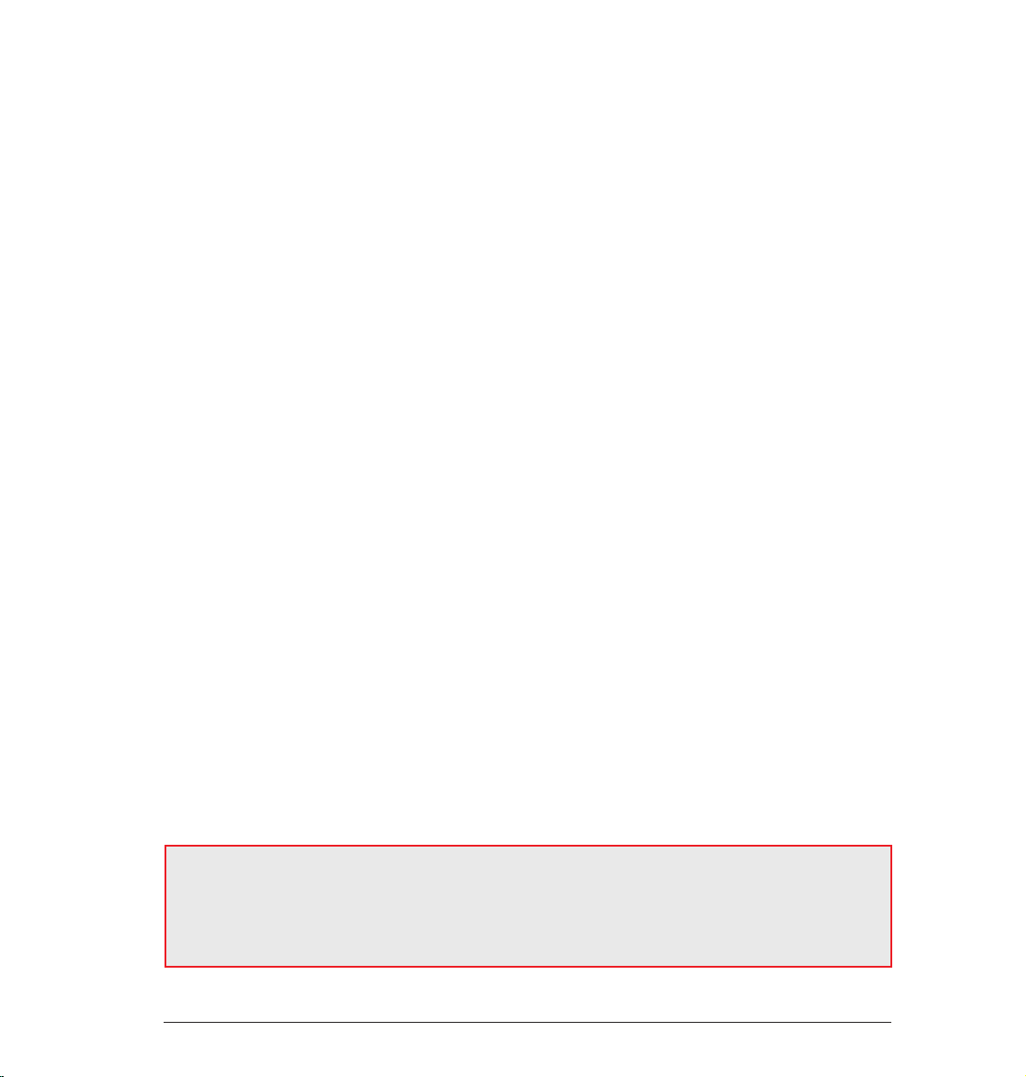
start with the most important step - starting BodyPaint 3D. After starting BodyPaint 3D you will see an image
similar to the following screenshot:
6. Icon Palette
(modes)
5. Object Manager
and color settings
1. Rendered Viewport
4. Attribute Manager Window
2. Texture Window
(UV Mesh Editor Window)
3. UV Manager
Here you see one of the two standard layouts: BP UV Edit. The second layout (BP 3D Paint) is set up in a similar
fashion, only without the UV mesh editor window which gives you more room in the editor window to paint.
2 Standalone Part 1
Page 7

1. Viewport
Here you can see the object you will be painting. You can rotate, move and zoom the window as needed. The
RayBrush mode lets you paint directly onto the object in the rendered version of the view. This gives you
control over the amount of color applied and can see right away how a new color looks on the object.
2. Texture Window (UV Mesh Editor Window)
This is where you edit your UV mesh. You can relax and restore your UV mesh. If you use the UV Manager’s UV
tools you can watch how the texture relaxes. You can also watch the color application process in this window,
which will then be visible in the editor window right away.
3. UV Manager
The UV Manager lets you restore the UV mesh using an algorithm. It recognizes layered polygons and attempts
to relax the UV mesh for optimal placement over the entire surface and, if necessary, new placement. All
remaining “relaxation“ can be adjusted manually.
4. Active Tool Window (Attribute Manager)
Different tabs display different brush types and their respective attributes as well as the UV Manager’s UV
tools.
5. Object Manager and color settings
We’re sure we don’t have to say much about the Object Manager. It’s the same manager as in the CINEMA 4D
main program and lets you select the object to be edited or change its position in the hierarchy.< This is the
CINEMA 4D Material Manager with expanded functionality. This is where you will find your textures with their
respective layers. If needed, you can paint in several layers at once (for example color and relief channels). To
do this simply select the texture to be painted and the respective layer and start painting.
6. Icon Palette
The command palette contains the Paint Setup Wizard, the Projection Painting and many other tools (that
you are probably used to using with 2D paint programs). The Paint Setup Wizard eliminates the need to
manually create a texture including the UV mesh. It also calculates the texture size and channels. Without
these bothersome preparations you can begin painting right away.
3Standalone Part 1
Page 8
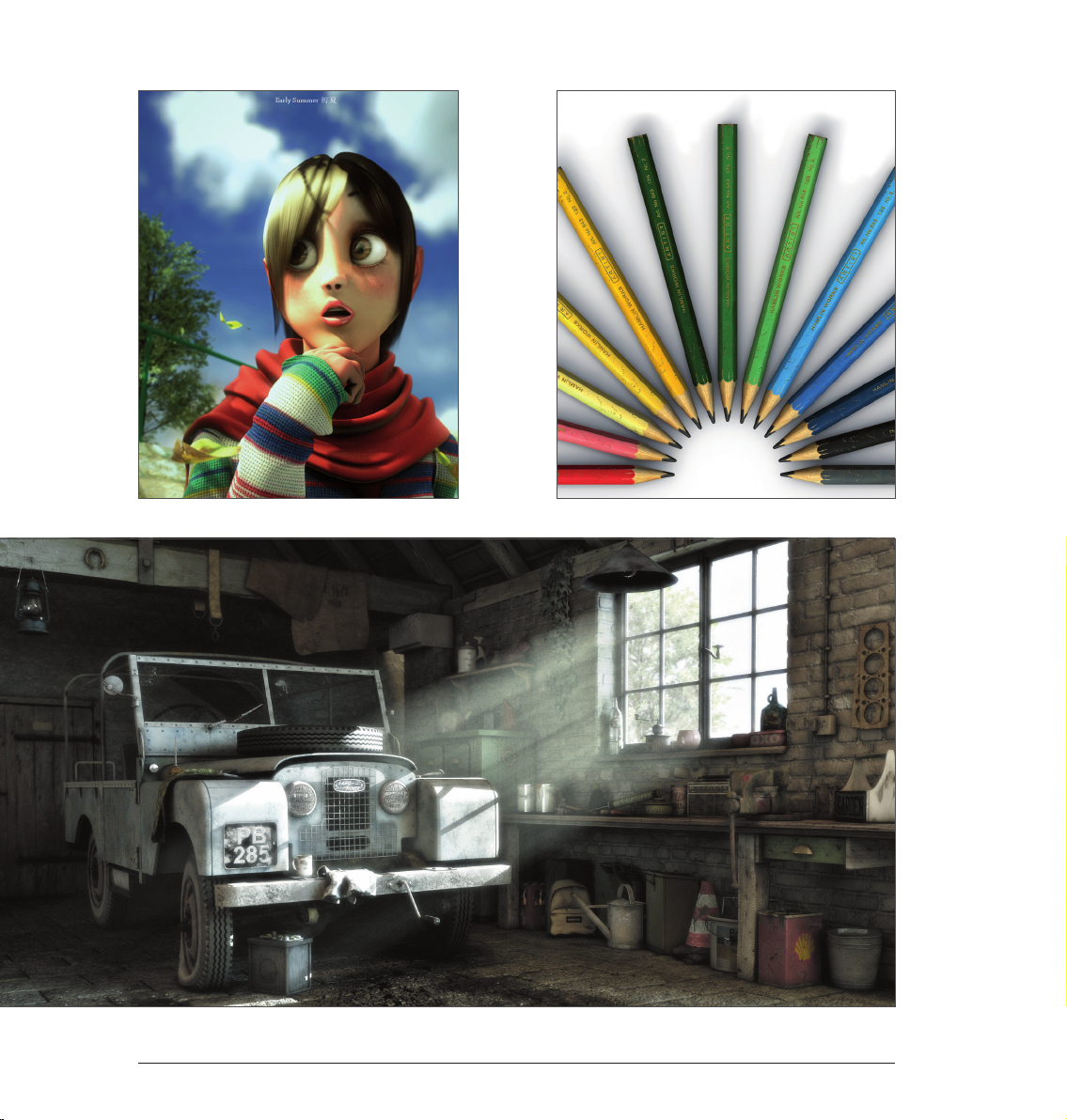
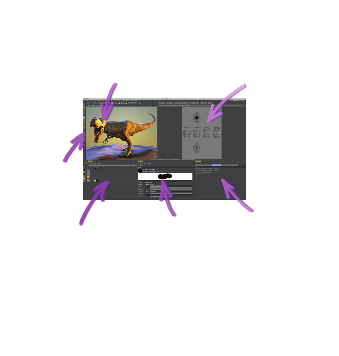
© Peter Bucholz
Sample Images4
Page 9
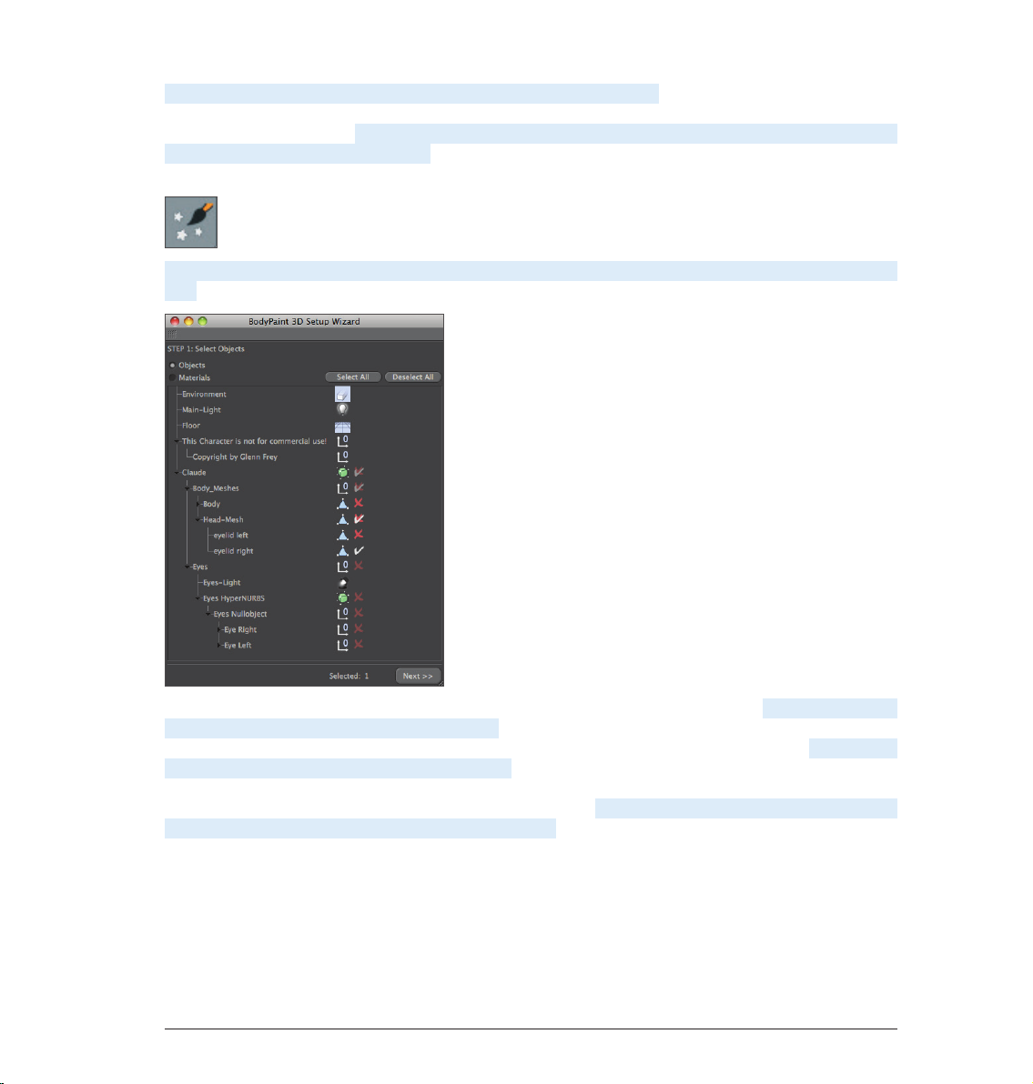
Now we’ll get to the heart of this tutorial. Open the file QS_BP3D_01.c4d. Say hello to Claude, our guinea pig
for the day. In the course of this tutorial we will alter the color of his right eyelid a little and apply a bump layer
in elephant-look to his skin. Select the predefined standard layout BP UV Edit at the top right and to the left
of BodyPaint 3D´s main editor window. Click on the Paint Setup Wizard Icon so we can make the necessary
preparations to the texture (brush icon with white stars).
Click on Deselect All in the window you just opened and apply a white check mark to the “eyelid right“ object
only.
We have just determined that a texture should be created only for the right eyelid object. Click on Next. Leave
the settings in the next window the way they are. The selection Single Material Mode would create a texture
for each object individually. If the box is not checked all objects will share one texture surface. Click on Next
again. In the next window check the bump channel. The color channel is selected by default. You can double
click the little gray boxes next to each texture channel and assign each channel a base color. Since Claude
likes elephant gray we will leave the boxes the way they are. Leave the rest of the settings the way they
are and click on Finish, then on Close in the next window. The basic textures have been created and we can
start painting. If you have experience with earlier texturing methods and the time it took to even get started
BodyPaint 3D will seem like a blessing to you. BodyPaint 3D saves you a lot of time. Now let’s move to the
second part of the tutorial: the UV meshes and the first brush stroke.
5Standalone Part 1
Page 10
3. Quick Tutorial: First Painting Lesson
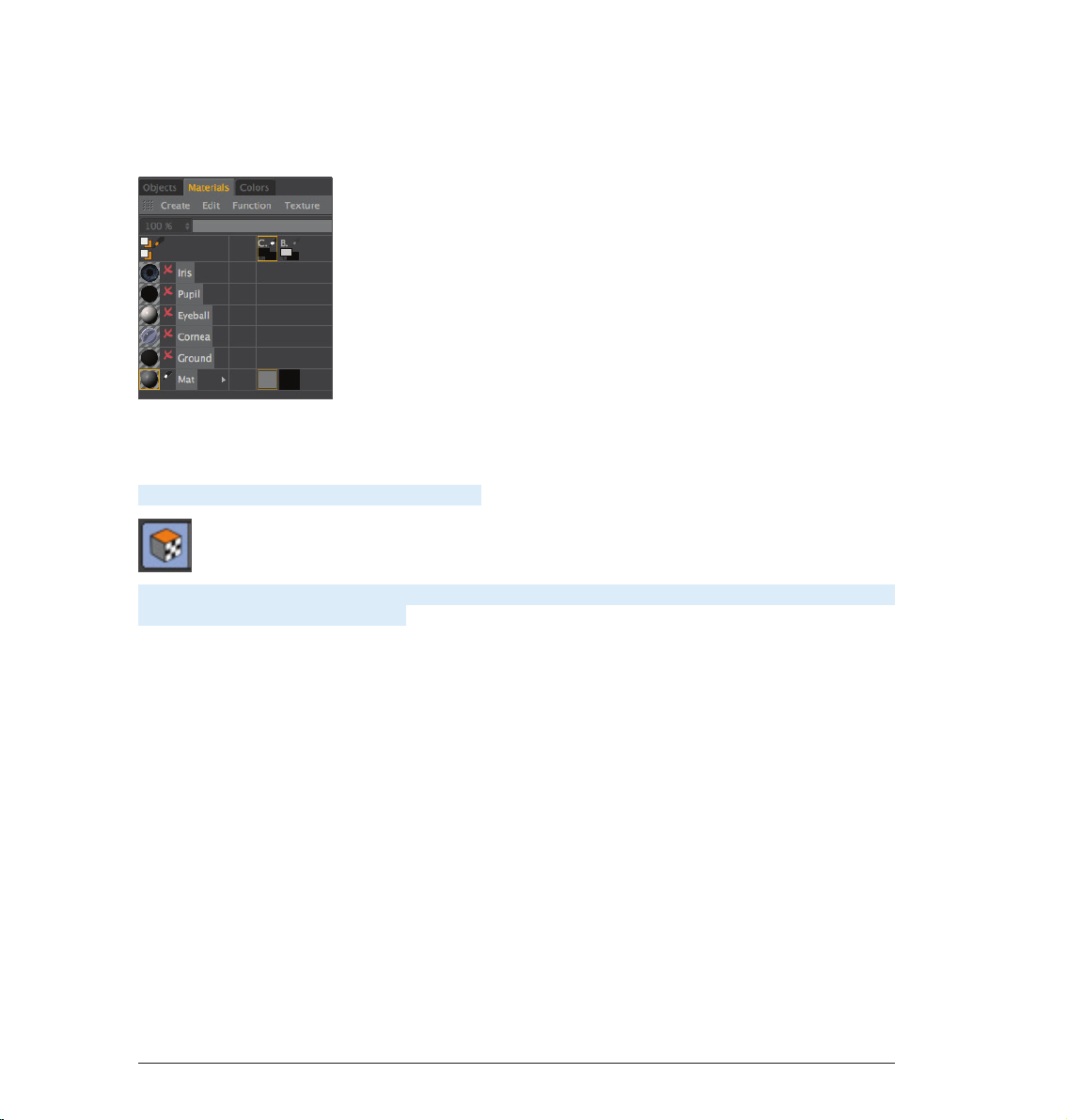
At the bottom left of the Material Manager (in the Materials tab) you will find the texture we just created, right
next to Mat.
This is the default name for a new texture. Of course you can rename the texture if you like. The first material
is the color layer and the second is the bump layer (at the top of the window you will see the abbreviations
which refer to these layers – C for color and B for bump).
Now Select the Use UV Polygon Edit Tool symbol.
Once you have selected the corresponding texture in the color channel the UV mesh should become visible in
the texture window at the upper right. If the mesh is not visible, activate it by clicking on UV Mesh/Show UV
Mesh in the texture window menu. Luck is on our side! The UV mesh looks good. The only thing that bothers
us is the fact that the edges of the eyelids are too small (highlighted in orange in the next image!).
6 Standalone Part 1
Page 11

The individual UV mesh polygons of these eyelid edges take up less texture area than the rest of the polygons.
That’s why a texture placed into the bump channel appears larger in these places (photograph of elephant
skin, for example). We can do without this, though, since we are painting our own skin structures onto the
surfaces and not using an existing texture. We can counter any distortion we encounter when painting
manually by using Projection Painting. The stroke will maintain its width no matter how the polygon is spread
over the mesh.
Move and zoom the editor window view until Claud’s right eyelid fills the view.
Now select Brush Tool for Painting Textures for applying the color. Set the size to 25 and the hardness to 40
in the brush’s Attributes Manager.
7Standalone Part 1
Page 12
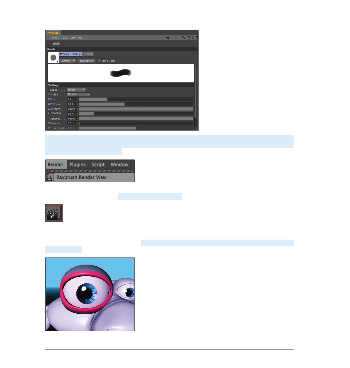
...and select a pink color using the Preview Active Channel directly below. If necessary, increase the Subdivision
Surface subdivision. Activate the Render Active View for RayBrush Painting in the active view in the Render
menu (BodyPaint 3D main menu).
(This will render the view and makes it possible for you to control the color application and the look of the
strokes for the final rendering). Activate Projection Painting
(You already know what this function does) and start painting. Of course BodyPaint 3D supports the use of
graphic tablets such as a WACOM Intuos. Painting objects with a pressure sensitive pen on a graphic tablet is
much easier than painting with a mouse. Paint along the edge of the eyelid. The eyelid will probably end up
looking like this:
8 Standalone Part 1
Page 13
If you move/rotate the figure now or click on the Apply Projection (click and hold on the Activate/Deactivate
Projection Painting button)
you will see how the color was applied to the texture (you can see the recently applied strokes of color in the
window to the right).
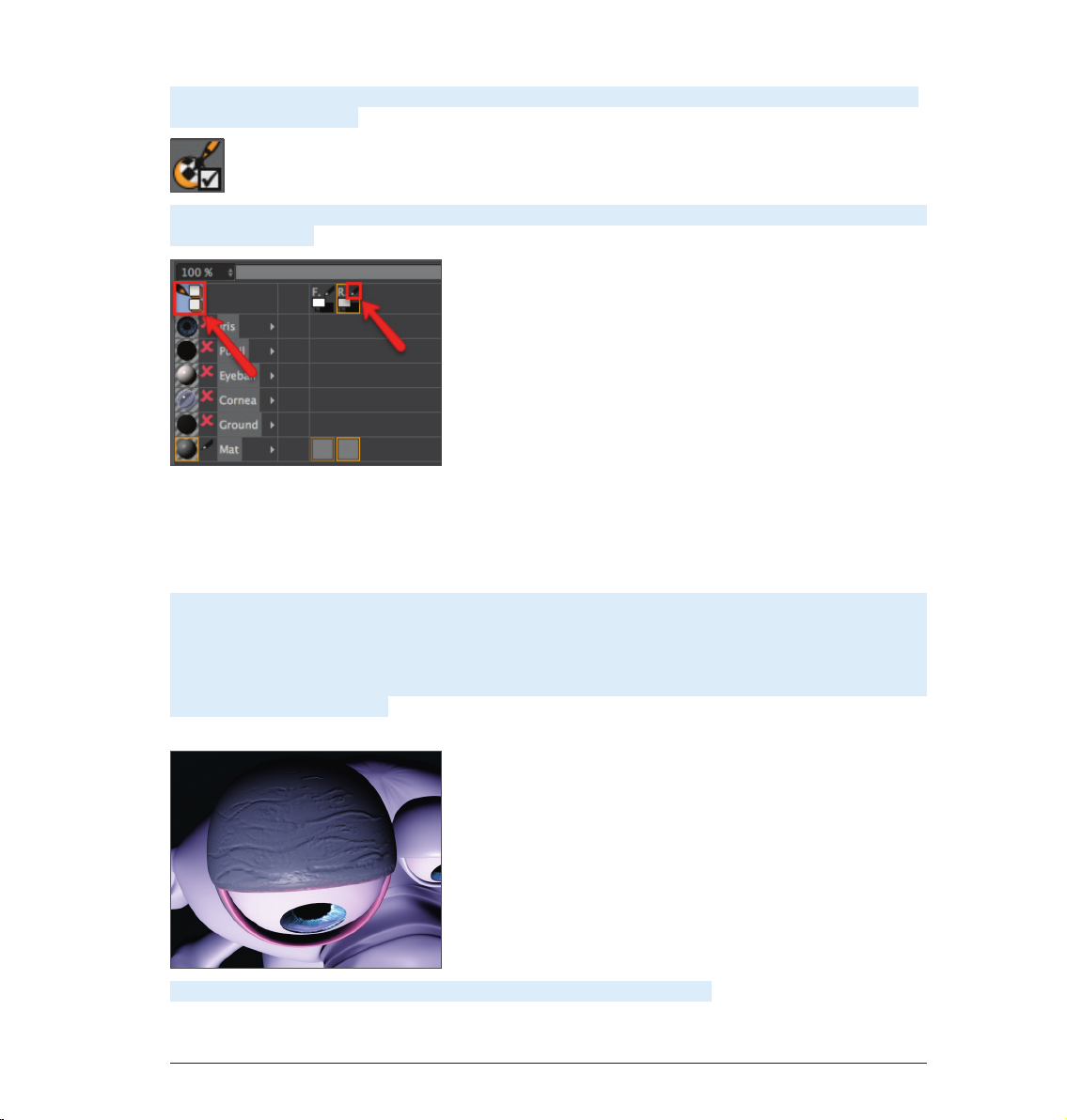
You can take the same steps for the bump layer. We will take you one step further, though, in order to be able
to explain an important function. We will paint both eyelids at the same time! Select the texture in the color
channel of the Material Manager. Now click on the icon with the black/orange pencil at the left of the Material
Manager. A light blue background tells you the multi-brush mode is active. Select the pencil icon next to the
B of the bump channel as well..
Rotate the view so you can see the eyelid from the top. Activate the Render Active View for RayBrush Painting
mode and set the brush size to 10. Switch to the color layer’s Color menu and set the color to a medium gray
which will be the base color for our eyelid. Now go to the bump layer’s color preview and set the color to black
(both color layers are located in the Materials tab under the letters C and B + pencil symbol). When you paint
on the object you will notice that both colors are being applied to the object – the gray base color and the
black (to indicate indentations). (If white were the color of the Bump channel it would “raise” the brush stroke
instead of indicating indentations). The result could look like the following image.
Load the QS_BP3D_01_Final.c4d file and take a look at it when you have time.
9Standalone Part 1
Page 14

4. BodyPaint 3D UV Edit
In this chapter we will show you more about editing UVs. First, though, you need to know what UVs are before
getting started. Take a look at the following screenshot:
The polygons of the sphere at the left are outlined in orange. Now imagine the sphere has a second invisible
skin lying over the polygon mesh. We will cut this skin open at selected locations and press it flat onto a
surface. This is our UV mesh (at right). This UV mesh is nothing more than a copy of our polygons in a flat state.
The UV mesh can be edited independently of the polygon mesh without affecting the polygons’ geometry and
vice-versa.
Each individual polygon has a UV counterpart with which it is linked, however each can be edited independently
of the other. This only applies to the shape of our polygons with regard to UVs and not, for example, to the
coloring. If part of a texture on which a UV lies is painted, the polygon linked to that UV will automatically
receive the same color. Hence, the mesh on the right can be painted and the result can be seen immediately.
Inversely, the sphere on the left can be painted and the result can be seen on the mesh to the right as the
painting occurs. Hopefully the basic function of UVs is now clear to you. Now you may be wondering how UVs
are edited and, more importantly, why.
We have created another screenshot (below) in order to better demonstrate this. What you should know first,
though, is that UV meshes aren’t always as neat and clean as the one used above, especially when working
with complex objects. The UV polygons of complex objects can often overlap when opened and flattened
(BodyPaint 3D does this for you automatically). Individual UV polygons can also be scaled oddly. Make sure
UV polygons do not overlap, causing them to share textures. If, for example, a hot pink were used to paint the
lips of a character and the UV polygons belonging to the lips overlapped with a few of the polygons belonging
to the side of the character’s neck, the hot pink color would be applied to these UV polygons as well. Unless
you’re designing an alien politician who talks out of the side of his neck this would probably be an unwanted
effect.
10 Standalone Part 1
Page 15
Now for our screenshot to clear things up:
At the right you can see the UV mesh with the underlying texture. We have added a white spot to the texture.
If you look closely you will see that two UV polygons overlap. This means that they share the same area of
the texture in the area in which they overlap. This result in the white spot being displayed twice on our sphere
(left). This can be quickly remedied by manually moving the UV polygons or points or by applying BodyPaint
3D’s Relax UV function. More on that later, though.
Once the UV polygons no longer overlap the next issue to avoid arises:
If, for example, a noise bump texture is used that should appear uniformly on a given obect, the UV polygons
should have more or less the same size. If a few UV polygons are much larger than the rest, the noise bump
texture would appear much finer on those larger surfaces.
Of course we have created corresponding screenshots to demonstrate this effect.
11Standalone Part 1
Page 16
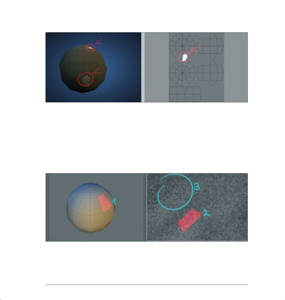
We have highlighted a polygon (red) on the sphere at left. At right you can see the corresponding UV polygon,
also highlighted in red. In order to clearly demonstrate what happens when a particular polygon is much
larger than the rest, we have greatly reduced the size of the surrounding UV polygons. Take a close look at the
right side of the UV mesh. The highlighted UV polygon takes up much more space then the surrounding UV
polygons. However the size of the corresponding polygons remains the same. Accordingly, the texture’s noise
will be squeezed onto the size of the respective polygon when rendered, resulting in a finer noise texture.
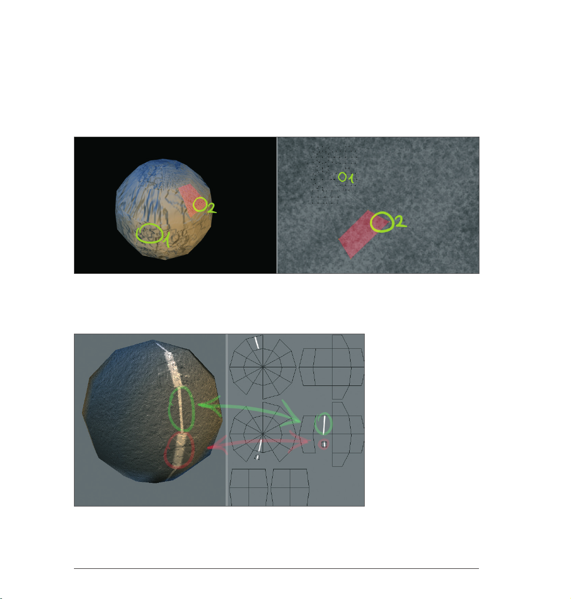
This can be seen clearly in the following screenshot:
Caption: The circled areas of our UV mesh on the right and the corresponding areas on the sphere (left).
The texture in area 1 is much more coarse than the texture in area 2. This is because the UV polygon of area
2 is much larger, causing the bump to be displayed much finer. A further example of the effect large UV
polygons have when applying color:
12 Standalone Part 1
Page 17
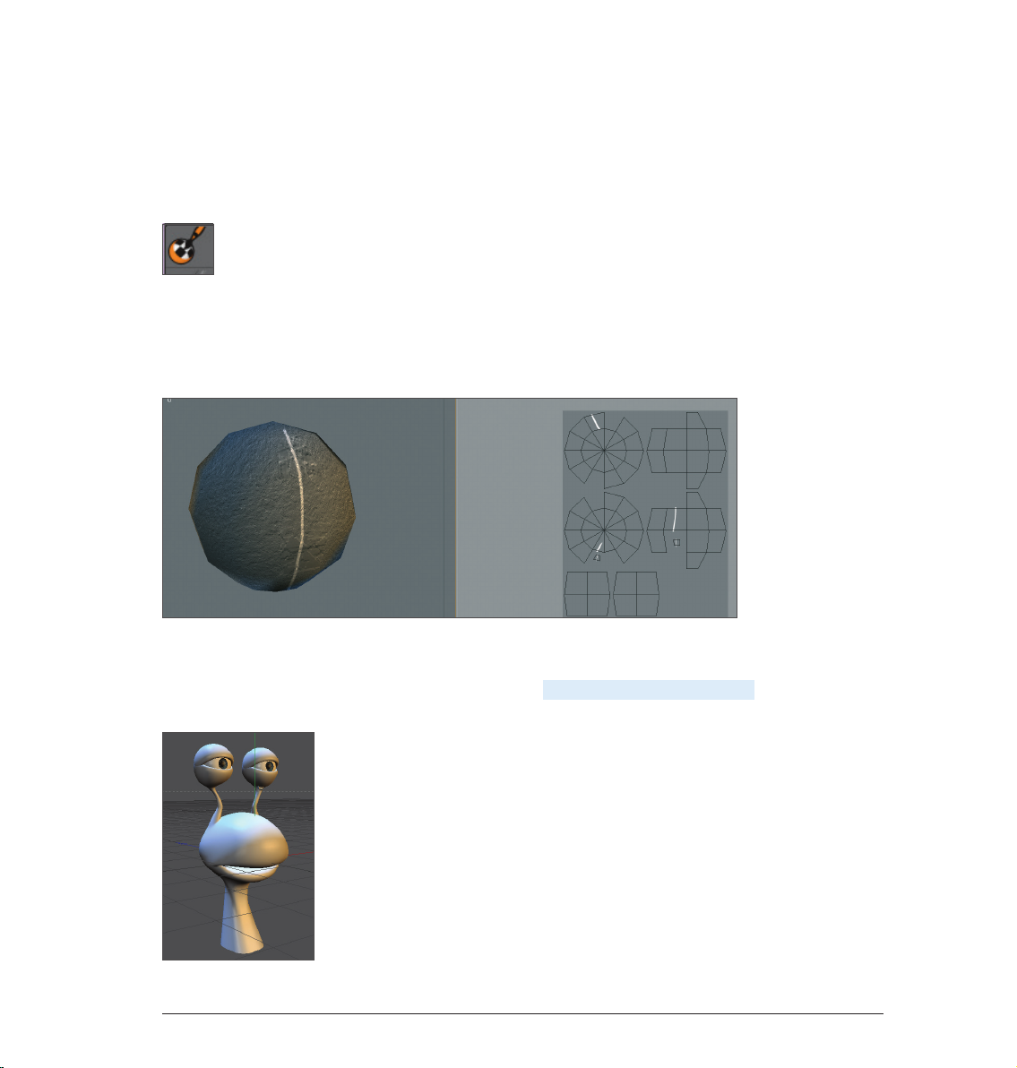
In the scene above we scaled down two UV polygons and subsequently drew a white line on our sphere from
top to bottom. You can see how the line width varies depending on the size of the UV polygons. The impression
is made that two different line strengths were used when painting, even though only a single line was drawn.
So what should you do if you paint your artistic stripe onto the sphere with a constantly varying brush strength
and the UV polygons also vary in size?
Answer: Use the newly integrated Projection Painting tool. You will find the icon in the Command Palette.
This intelligent little tool keeps the brush thickness from being varied and makes sure that the line is applied
equally onto the object. The artistic stripe you painted will be varied in width only on the texture under the
UVs. The line in the next screenshot was painted using Projection Painting. Take a look at the different line
strengths on the UV mesh at the right. At those locations where the UVs are small the line width will be
narrower as well.
It is very important that you understand this basic concept when working with BodyPaint 3D in order to
achieve optimal results.
In the following we will take a closer look a the UV tools. Open the file QS_ BP3D_02.c4d. This file contains a
snail’s head whose UV polygons we will prepare for painting.
13Standalone Part 1
Page 18
Start by switching to the default layout BP UV Edit at the top left right of your interface.
We have just switched to BodyPaint 3D’s UV edit interfa ce. The functions contained in this layout are sp ecifically
designed for the editing of UVs. Next we will create a material with the corresponding UV polygons. To do so
click on the Paint Setup Wizard tool, located in the Command Palette above.
In the window that appears, click on the top white check mark and subsequently click on the Next button twice,
once on Finish and once on Close.
We have just created a texture for the Color channel. At the right you should now be able to see our UV
polygons. If not, activate the Show UV Mesh option in the menu from that window’s UV Mesh menu.
14 Standalone Part 1
Page 19
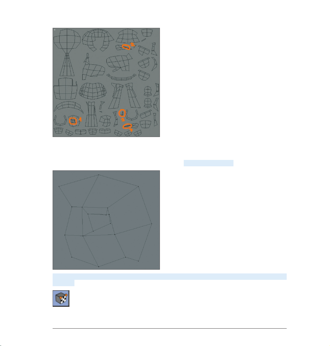
The Paint Setup Wizard saves us from having to manually peel the UV skin off of our character and has
flattened it neatly onto our texture. Our mesh looks quite good at first glance. However, if you look closely,
a few spots can be found that need working on, which we have circled for you in orange. Areas 1 and 2 have
overlapping and the polygons in areas 3 and 4 are too small. First, zoom in to area 1.
As you can see, two UV polygons overlap in the center. In order to correct this, first activate the Use UV Point
Edit tool...
15Standalone Part 1
Page 20

...then activate the Move tool...
...and rearrange the corresponding points until the UV polygons no longer overlap.
The remaining areas (2-4) can also be corrected using this method. Refer to the following screenshots if you
need help:
16 Standalone Part 1
Page 21

Once all problem areas have been corrected the mesh can be painted. The method we just described was the
manual method of fixing such problem areas. However, BodyPaint 3D also offers tools that will automatically
“relax” complex UV polygons and we will turn our attention to these tools now. Open the file QS_BP3D_03.
c4d. The geometry in the area of the monkey’s missing nose is perfect for our demonstration (note that no
animals were hurt in making this tutorial. All animals are trained virtual professionals!).
If not already there, switch to the BP UV Edit layout.
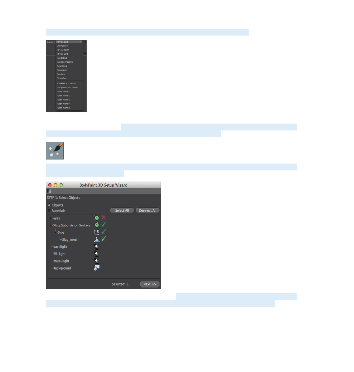
Start the Paint Setup Wizard...
...and click twice on Next, once on Finish and finally on Close. As in our first example, you will see the UV mesh
appear in a window at the right of your interface. Select the Use UV Polygon Edit tool from the Command
Palette at the top and open the UV Mapping tab in the UV Manager at the bottom right of your interface. Once
in the UV Mapping tab, go to the Projection page.
17Standalone Part 1
Page 22

Set Projection to Frontal. Now select other types of projection by clicking on the corresponding button to
see the different types of projections that are available. Once you’ve taken a look at them all, switch back to
Frontal mode. Frontal mode reflects the active editor view. This is also why we have chosen this mode for our
monkey’s face.
As you can see, the UV polygons in the area of the monkey’s nose are overlapping. We will now use the
BodyPaint 3D Relax UV tool to take care of this little problem. Open the Relax UV page in the UV Manager’s
UV Mapping tab. On this page you will see an Apply button. Make sure to deactivate the Pin Border Points and
Pin To Neighbors options and click on Apply. The UV mesh will be markedly relaxed.
Left: Before applying Relax UV. Right: After applying Relax UV.
Each UV polygon now lies next to another and no UV polygons overlap. Doing this manually would have
practically been impossible and may even have led to a few nervous breakdowns among our readers. That’s it,
our UV mesh is now ready to be painted. As you can see, just a few steps are required and you can turn your
attention to the creative part of your work - painting your object’s UV mesh.
18 Standalone Part 1
Page 23

5. BodyPaint 3D Exchange Plugin
Before we get started we want to pass on some important fundamentals to you.
By default, BodyPaint 3D saves images in .tiff format, which can also contain layers. When these images are
subsequently loaded and re-saved in foreign applications, these layers may be lost. If you use Photoshop for
editing your images you can also set your BodyPaint 3D default image format to .psd (Photoshop).
The files BodyPaint 3D requires to communicate with foreign applications (e.g. Maya, 3ds Max, XSI or LightWave
3D) can be found in the BodyPaint 3D program folder under “Exchange Plugins” or on our web site at www.
maxon.net in the Downloads section. Make sure you copy all necessary files for the applicable software to the
corresponding directory. If using Maya the files must be loaded and executed in the following order using the
Script Manager: BodyPaintExchangeLoadPlugin.mel; BodyPaintExchangeUI.mel; usersetup.mel. (refer to your
BodyPaint 3D reference manual for additional information).
For Maya, the object exchange, including textures, is done using the corresponding menu command.
(Please refer to the BodyPaint 3D reference documentation (Main menu/Help) for information regarding the
location of the corresponding BodyPaint 3D exchange plugin for your software). Exchanging objects is very
easy. Take an object, send it to BodyPaint 3D using the Send to BodyPaint command (BodyPaint 3D will be
started automatically), paint your object in BodyPaint 3D and send it back to your application using the Send
Scene Back command.
Geometry-, material-, light-, UV- and any available texture data will be exchanged. Your BodyPaint 3D
reference manual provides more information regarding the preparation of files for use with exchange plugins.
The following information applies to use with Maya:
19Standalone Part 1
Page 24

MAC
[Maya 5]
Macintosh HD / Applications / Alias Wavefront / maya 5.0 / maya
• Right-click on the Maya executable file and select Show Package Contents.
The path will be the following: Contents / MacOSClassic / plug-ins.
• The scripts belong here: Macintosh HD / Users / Shared / Alias / maya / scripts.
[Maya 6]
Macintosh HD / Applications / Alias / maya 6.0 / maya
• Right-click on the Maya executable file and select Show Package Contents.
The path will be the following: Contents / MacOS / plug-ins.
• The scripts belong here: Macintosh HD / Users / Shared / Alias / maya / scripts.
[Maya 6.5]
Macintosh HD / Applications / Alias / maya 6.5 / maya
• Right-click on the Maya executable file and select Show Package Contents.
The path will be the following: Contents / MacOS / plug-ins.
• The scripts belong here: Macintosh HD / Users / Shared / Alias / maya / scripts.
[Maya 7]
Macintosh HD / Applications / Alias / maya 7.0 / maya
• Right-click on the Maya executable file and select Show Package Contents.
The path will be the following: Contents / MacOS / plug-ins.
• The scripts belong here: Macintosh HD / Users / Shared / Alias / maya / scripts.
20 Standalone Part 1
Page 25

PC
[Maya 5]
• Plugin: C: \ Programs \ AliasWavefront \ Maya5.0 \ bin \ plugins
• Scripts: C: \ Documents and Settings \ username \ My Documents \ maya \ 5.0 \ scripts.
[Maya 6]
• Plugin: C: \ Programs \ Alias \ Maya6.0 \ bin \ plugins
• Scripts: C: \ Documents and Settings \ username \ My Documents \ maya \ 6.0 \ scripts
[Maya 6.5]
• Plugin: C: \ Programs \ Alias \ Maya6.5 \ bin \ plugins
• Scripts: C: \ Documents and Settings \ username \ My Documents \ maya \ 6.5 \ scripts
[Maya 7]
• Plugin: C: \ Programs \ Alias \ Maya7.0 \ bin \ plugins
• Scripts: C: \ Documents and Settings \ username \ My Documents \ maya \ 7.0 \ scripts
In contrast to MacOS, Maya scripts must be installed for each user separately in Windows.
21Standalone Part 1
Page 26

6. Tips and Tricks
• A very helpful function can be found in BodyPaint 3D’s preferences (Ctrl+E). In the BodyPaint menu you will
find the function Project On Invisible Parts. Which, when activated, can make your work a lot easier. Let’s
assume you want to color the arm of a figure or sprinkle color on the entire figure. You would have to apply
the color with this function deactivated, rotate the arm, apply the color, rotate the arm and, well, you get
the idea. When this function is activated you apply the color in the front view and the color is applied to all
surfaces lying behind this surface at the same time. Just make sure you don’t apply color to objects you
don’t want to color when this function has been activated.
• If a texture map does not fit correctly at the point where large and small polygons meet (in the case of
low-poly objects that are subordinates of Subdivision Surface) set the Tile UVs function, in the respective
Subdivision Surface Object’s Attributes Manager, from User to Border or Edge. This sends the UV mesh
through the Subdivision Surface algorithm and subdivides it to fit the polygon object. Make sure the
Subdivision Surface type is set to Catmull-Clark (without N-Gons). Otherwise this function will be disabled.
• Avoid UV polygons that meet to a point when applying a noise texture to a bump layer. The narrower a
3-sided polygon becomes, the coarser the bump noise channel will be rendered. Of course such a polygon
has much less area for the noise structure at its tip than it does at its center which results in a magnification
effect of the noise structure. Try to set up each side of a triangulated polygon as an isosceles. This also goes
for “4-point polygons“ when they converge into a trapezoid. The more square the polygon the more even
the structure will be.
• It goes without saying that you need different brushes for different texture looks. BodyPaint 3D has a wide
variety of brush types for you to use. Just select the brush Tool and click on the small black arrow on the
brush preview.
• Here you will find all the brushes your heart desires. If you don’t find the brush you’re looking for we’ve beat
Murphy to the punch and have given you the possibility to create and save your own brushes. Just make the
changes you want and click on the Add Preset Save Brush button.
• With this tutorial you have gotten to know how BodyPaint 3D works and you can convince yourself of the
advantages painting directly onto objects themselves offers. With only a little practice you can also achieve
similar results as you can see on the next image – Claude’s new texture outfit.
22 Standalone Part 1
Page 27

Here the same rule applies for best results: Try it, don’t just study it!
23Standalone Part 1
Page 28

BodyPaint 3D R16 Standalone Part 2
Additional functions
1. Introduction
The purchase of BodyPaint 3D R16 Standalone lets you do more than just paint objects. With it you can also
model, texture, animate and set lights. We will explain a few of these core functionalities in the following
tutorials.
No matter if you work in the field of print, advertising, design, visualization or film, BodyPaint 3D gives you all
the tools you need to make your ideas reality. In order to give you an impression of what to expect from the
interface we’ll go straight to Part 2 of the BodyPaint 3D standalone Quickstart tutorial – the standard layout.
2. General Information/Standard Layout
Rendered Viewport
Icon Palette
(modes)
Viewport
(perspective view)
Icon Palette (tools)
Material Manager Coordinates Manager
Object Manager
Attribute Manager
24 Standalone Part 2
Page 29

The primitives are located in the Primitives command group. It contains all of BodyPaint 3D’s available
predefined parametric objects.
One click and the world’s most used object is created – the cube. Click and hold to see all available parametric
objects. This is where you choose the initial shape you will need. And don’t forget that only parametric objects
that have been converted to polygon objects can be edited at a polygon, point or edges level!
Note: After an object has been initially created it is basically a parametric object. A parametric object can only
be modified as a whole and not its individual surfaces (an exception are special deformers from the Deformer
menu). Before you begin modeling, the parametric object must be converted to a polygonal object. To do
so, select the object you want to convert and run the Make Editable command by pressing the c-key on your
keyboard. You can now move or modify individual points and surfaces. Two symbols to the right of the Cube
Primitive symbol (black cage with white points and turquoise inner) are the Generators. The most important
of these is the Subdivision Surface object.
The next group icon hosts probably the most important BodyPaint 3D object, the Subdivision Surface object.
25Standalone Part 2
Page 30

If a polygon object is a Child object of a Subdivision Surface object its polygon wireframe (mesh) will be
subdivided to a higher degree. If an object is made a Child of a Subdivision Surface object its subdivisions
will be increased virtually, which will give the object a softer look. As you can see in the next screen shot:
The outer mesh (light blue) shows the polygon cube’s actual subdivision. The finer inner mesh (blue) shows
the subdivision of the Subdivision Surface object. Change the cubes’ display mode by selecting (deactivating)
Options/Isolines in the Viewport’s menu and switching to Gouraud Shading (Lines) in the Editor’s Display
menu. In the end it’s up to you how you want your objects displayed in the same menu. Then switch to the
Use Polygon Mode in the left Icon Palette. However, for this tutorial, this is the most effective way to show the
effect Subdivision Surface objects have on polygonal objects or primitives since it shows how the cubes are
subdivided and the final result is therefore also easier to visualize.
The advantages, especially in modeling, are obvious. Since the object contains few points (edges / polygons)
that can be edited it remains very manageable. You can drag just one point of the original wireframe and
the Subdivision Surface mesh, with its finer subdivision, will follow the virtual point being dragged (see next
screenshot).
If the polygon object were made up of such fine subdivision modeling, it would be much more complicated.
You would pull one point and only one point would be moved. All other surrounding points would retain their
position. You would have to move each one individually in order to achieve the desired shape.
26 Standalone Part 2
Page 31

© Bill Ledger – ToyBox Animation
Sample Images 27
Page 32

© Kevin Capizzi
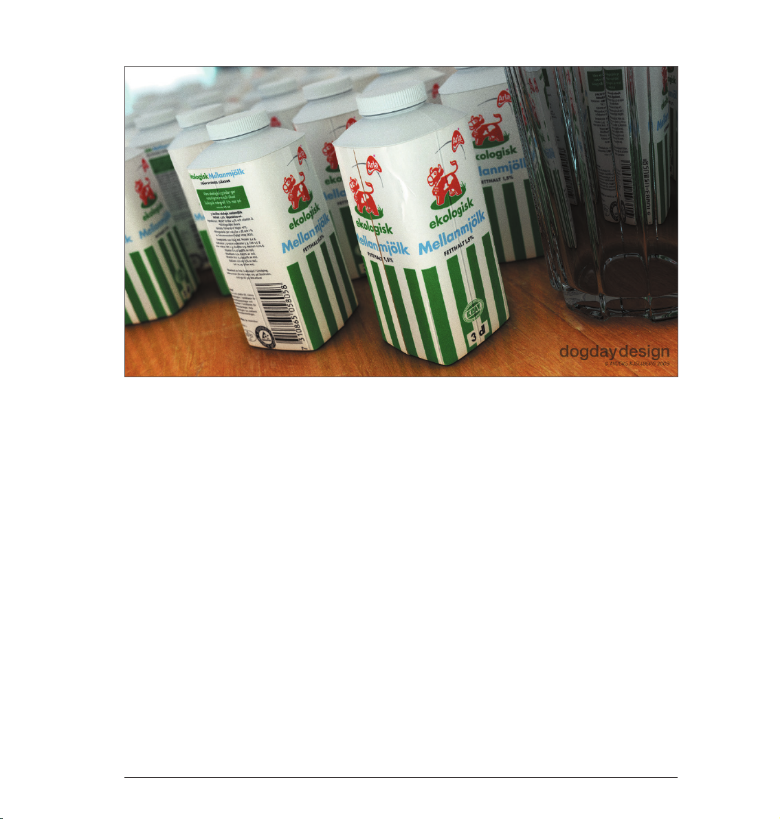
© Anders Kjellberg – www.dogday-design.com
Sample Images28
Page 33
© Anders Kjellberg – www.dogday-design.com
Sample Images 29
Page 34

3. Quick Tutorial: Materials
A well-modeled object can make a mediocre impression if the right textures aren’t used. Textures give a model
color, highlights, structure and other important surface properties. A texture placed into the bump channel,
for example, gives the object’s surface an uneven, bumpy look without actually altering the geometric
structure. This effect can be used to imitate skin wrinkles, scars or the surface of an orange. The displacement
channel works in a similar fashion, only that it actually does change an object’s geometric structure. Using
the luminance channel you can give an object’s surface a self-illuminating property or integrate a Subsurface
Scattering effect (SSS) which lends the surface a slight translucent/reflective look, like human skin or candle
wax, for example. In short: Textures have the same significance as the outer shape of an object because they
are necessary for achieving the desired atmosphere, coloring and surface structure.
We will begin with a brief introduction to the individual material channels:
Color: This is where the material’s color or the base color for the texture is set.
Diffusion: This channel makes your texture irregular. Through the application of a shader or a texture
your object receives a dirty or dusty look. If desired it can also influence the Reflectance and Luminance
channels, respectively, and the specular highlight.
Luminance: The material is given an illuminative property which is also taken into account in the
Global Illumination calculation.
Transparency: This is where you determine the material’s transparency.
Reflectance: Gives the material reflective characteristics and defines the material’s highlights and
highlight colors.
Environment: A texture is used to simulate an environment reflection.
Fog : This channel lets you apply a fog property to a material.
Bump: Uses an optical trick to translate light and dark elements of a texture or a shader to simulate
the height and depth of an uneven surface. Scars, wrinkles or scratches can be simulated using this
channel.
Normal: This channel is meant for use with normal textures. Normals give a low-res polygon object
a hi-res look when RGB textures containing the required properties are applied. This lets a hi-res
polygon object be replaced by a low-res object, thus saving a lot of render time and offering the same
visual result.
Alpha: A texture’s transparency is determined by a material’s light and dark areas. Black equals a
transparency of 100 % and white makes it opaque.
Glow: Gives the object a self-emitting glow.
Displacement: Deforms an object using light and dark values (calculates differences in height). Do not
confuse this with the Bump channel which only imitates an uneven surface.
30 Standalone Part 2
Page 35

We will now create our own material. Open the QS_Material.c4d file. You can see in the Object Manager to
the right that the object does not yet have a texture applied to it. Click on file/new material in the Material
Manager at the lower left.
A standard material has been created. If you click on this material its properties will be made visible in the
Attributes Manager to the right. In the Basic menu you can determine which channels should be activated for
this material. Go ahead and activate the Bump channel. As soon as you have done that a new menu button,
Bump will appear. Now click on the menu button Color and load a texture into the material by clicking on the
small arrow next to Texture. Choose Load Image and load Iristexture.jpg. In the mini-preview of the Material
Manager at the lower left of your screen you will see the texture displayed as soon as it has been loaded. This
gives you a good overview of the materials being used in the scene.
Repeat this procedure for the Bump channel and load Iristexture_bump.jpg into the channel. This JPEG
contains the gray scale version of the iris texture which we need to create a relief effect for the surface. You
can also choose Filter (click on the small light gray arrow next to the word Texture in the Bump channel) and
load the color texture here and set its saturation to 100 %. This saves you from having to load a second image.
The bright areas of the image will later appear to be raised on the object and the dark areas of the image will
appear to be somewhat indented. A true deformation of the object will only take place in the Displacement
channel. The Bump channel does not alter the polygon’s surface but uses an optical illusion to give the surface
its structure.
31Standalone Part 2
Page 36

Click on the material in the Material Manager with the left mouse button and drag it onto the object eyeball
in the Object Manager. (When you drag the material over the object you can let go once the little white arrow
points down). Alternatively you can drag the material onto the desired object (the eyeball) directly in the
Editor. Just make sure you drop the material onto the correct object if there are several in the scene or in
close proximity to one another. You can check in the Object Manager to make sure the material was dropped
onto the correct object - the material icon will appear next to the object onto which it was dragged.
You have probably noticed that the eyeball brightened somewhat after you applied the material but you aren’t
able to see the actual texture. We still have to change the offset properties and the mapping size so the
texture will be aligned properly on our object. At the moment the actual image of the iris is lying distorted on
the right side of the eyeball. You can check this by making both Subdivision Surface eyelid objects invisible for
the editor. To do this double-click on the top small gray dot to the right of the object in the Object Manager
(until it turns red).
Double-click on the dot again and it will turn green, which makes the objects visible again independent of the
visibility settings of any parent object. The dot directly below has the same function except that it affects the
rendering. Once you have made the eyelids invisible and have rotated the view a little the eyeball should look
as follows:
Switch the visibility of the Subdivision Surface objects back by clicking again on the dots next to the object in
the Object Manager, making them gray. Click on the Texture Tag at the right of the Object Manager next to the
object. It’s the material that we applied to the eyeball. You can recognize it in the mini preview of the texture
in the Object Manager.
32 Standalone Part 2
Page 37

Once you have selected it you will see its parameters in the Attributes Manager. Adopt the settings you see
in the next screenshot:
We have just aligned the texture on the eyeball mesh by changing the Length U and Length V parameters. The
offset setting put the texture in the correct position. If you rotate your view again you will see that the iris
texture is positioned correctly.
Tip: If you want to undo an accidental change to the view just press Cmd+Shift+Z (Mac: Cmd+Shift+Z). This
function is useful if you have inadvertently rotated the perspective view instead of the editor view. You can also
select edit/undo view in the main menu of the editor view. The texture will complete our model. Experiment
with the parameters of the individual channels to find out how they affect the material. At this point we would
like to offer you a few additional tips.
33Standalone Part 2
Page 38

If you own CINEMA 4D Visualize or CINEMA 4D Studio you can render human skin, for example, very realistically
using Subsurface Scattering. The shader Surface Scattering makes it possible. By placing this shader in the
luminance channel (click on the small arrow next to Texture and select Subsurface Scattering from the Effects
menu/Subsurface Scattering) the effect is created when rays of light meet a slightly transparent object.
Some rays infiltrate the object further and are dispersed, others are directly absorbed or bounce off. Further
possible uses for this effect would be for materials such as plastic, milk, candle wax or figurines made of jade.
You can load black-and-white textures into the alpha channel to influence the material based on the texture’s
brightness, similar to the way you would use them for the bump or displacement channels. The texture’s black
areas would be rendered with a transparency of 100 %. As the texture becomes brighter the transparency is
reduced accordingly. White would have a transparency of 0 %
If you choose Shader instead of New Material under create in the Material Manager you will see a list of shader
presets. The advantage of these shaders is that you don’t have to worry about mapping your texture or seams
in your texture because a 3D shader will be calculated for the 3D space. Here are a couple described in detail:
Cheen: Generates an electron microscope effect. Danel: Very good for simulating high-gloss finish
34 Standalone Part 2
Page 39
Banzi: Lets you depict various types of wood.
Banji: Calculates complex lighting situations with glass and even makes rear-projection (shadow casting) on
partially transparent materials such as rice- or canvas paper possible.
35Standalone Part 2
Page 40

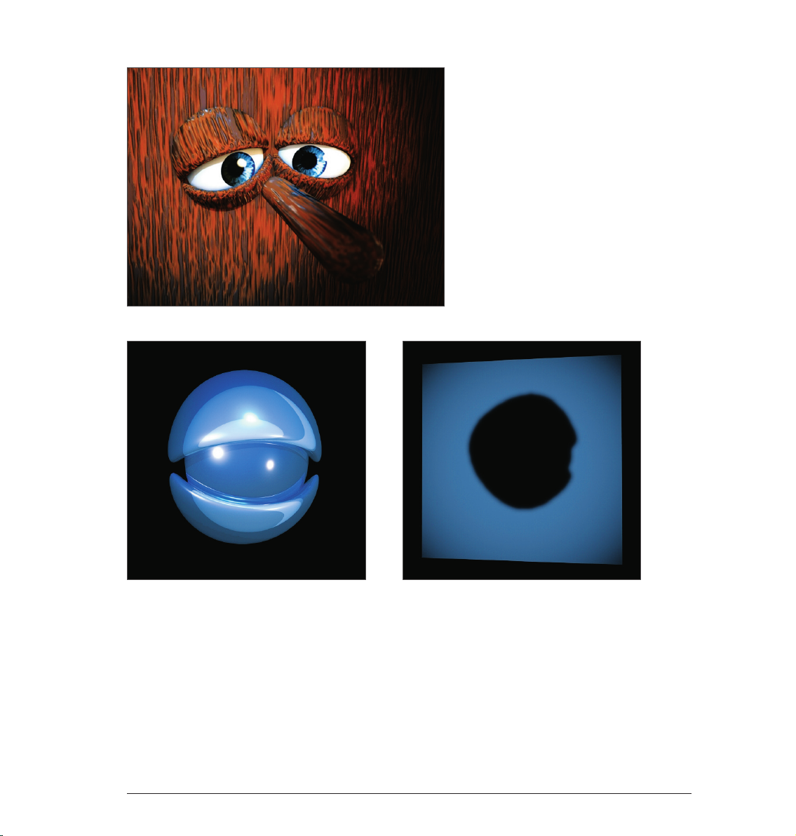
4. Quick Tutorial: Light
If you are already familiar with lighting a scene in the real world then you will feel right at home with the
BodyPaint 3D light objects. They can do everything real lights can do – and quite a bit more. In this tutorial
we will set up a 3-point lighting arrangement. This type of arrangement is used often in portrait photography
to achieve an even lighting and is an excellent method for lighting an object quickly and professionally in the
3D world Open a new (empty) scene. Create a floor object Create/Environment/Floor). Our little amphibian
man will be our lighting victim. Merge the file, QS_Light.c4d into the scene (Main menu: File/Merge). Adjust his
position so he’s standing on the floor. Adjust your editor view so the entire figure is visible to you.
A 3-point lighting arrangement begins with setting a key light. As the name suggests, this light emits the
main lighting for the scene and will cast the main shadows. Create a light object (Objects/Scene Create/Light/
Light). Name it Main_Light (double-click on the name) in the Object Manager.
BodyPaint 3D has several different types of light sources. The key light will always be created by default. A
point light emits from its center in all directions. For our key light we will need a spot light which we can aim
directly at the object. To make the key light a spot simply go to the Attributes Manager and switch the light
from Point to Spot.
36 Standalone Part 2
Page 41

Now our light source has been transformed to a spot. A spot acts like a flashlight. BodyPaint 3D offers spots
with square and round cones of light. This cone is visible in the editor and can be manipulated. Now we will
aim the spot at our figure.
Position the light at the following coordinates in the Attribute Manager:
X= 300
Y= 580
Z= –300
at an angle of
H= 45
P= –45
degrees (enter the values and click on the Apply button).
Render the scene (Cmd/Ctrl + R).
37Standalone Part 2
Page 42

The light now falls at an angle onto our object (If this is not visible in the Editor it may be due to the fact that
your display mode is set to Quick Shading (uses a single default light source) instead of Gouraud Shading (uses
all scene lights)). Of course the exact position of the light is strongly dependent upon the camera’s angle.
Unfortunately the light is not casting a shadow, letting the figure look like it’s floating. CINEMA 4D’s lights
have an advantage over real light in that you can choose which kind of shadow, if any, they should cast - a plus
for any studio photographer. In the General menu of the Attributes Manager, set the light’s shadow to Shadow
Maps (Soft). We don’t want the shadow to be completely black so we’ll make it a little transparent.
In the Shadow menu, set the shadow density to 50 %. Select 1000 x 1000 as the shadow map. Render the
scene.
38 Standalone Part 2
Page 43

BodyPaint 3D offers three types of shadows: RayTraced (Hard) – a shadow with sharp edges, Shadow Maps
(Soft) – a shadow with soft edges and Area – a shadow that becomes softer the further it’s away from the
object, resulting in the most realistic shadow effect. Try the other two shadow types. Careful, the area shadow
can take a long time to render! The larger shadow map allows the shadow to be rendered more accurately.
The light’s cone is a little too small. We will change this as follows:
Switch to the details menu in the Attributes Manager and set the Inner Angle to 30 degrees and the Outer
Angle to 100 degrees.
You will see the result in the editor right away. You can also edit the light’s cone by dragging the orange
handles (If your graphics card will support it you can set the editor’s display mode to Enhanced OpenGL with
activated shadows. (Viewport: Options/Enhanced OpenGL) Generally speaking, OpenGL offers a much more
precise depiction of your scene and gives you an impression of how the shadows will fall).
39Standalone Part 2
Page 44

Now we’re happy with our key light. Next we will create a more even lighting by brightening our figure a little
from the other side.
Create another light source in the scene and name it “Brightener”. Place it at the following coordinates:
X= –360
Y= 225
Z= –230
Select Area as the type of light.
Since the brightness of the lights in the scene is additive, we must “dim“ the brightener a little.
Reduce the Intensity in the General menu to 40 %.
This area light illuminates the figure from a different angle and softens the contrast somewhat. It won’t cast a
shadow since this would cause “crossing“ of the shadows and make the object look bad.
40 Standalone Part 2
Page 45

The scene is now pretty evenly lit, but we want to give it a little more pep. Create another light source, name
it Color and, in the Attributes Manager, set its type to Infinite. Set its color to turquoise and set its H angle to
–160. The position of an infinite light is irrelevant since it always lights your scene in the direction of the Z axis.
This is why we will leave it at the point at which it was created. It gives our Amphibian an interesting color edge
and sets him off of the background a little.
Your scene’s mood can be changed by simply changing the color of some of the lights used.
That completes our classic 3-point lighting arrangement. Now the real work starts. If the scene has a
background, which is often the case, it will have to be lit as well. With the proper use of point lights details in
the scene can be “brought to light“ very nicely. But don’t overdo it. With good lighting, less is often more. Only
add lights when necessary and if the scene can actually benefit from them. Two more tips before we end: If you
have several lights in a scene and are not sure which light is lighting what, simply turn off (green check mark)
all other lights in the Object Manager. The light which remains will be the only one visible.
There is a trick how you can determine how to best light which objects in your scene. Select the desired light in
the Object Manager and activate Link Active Object in the editor view’s Cameras menu. Selecting this option
lets you view the scene from the point of view of an active object, in our case the light. Moving the editor view
will automatically change the position of the light when in this mode. This way you can see how the change of
position of the light affects the lighting of the object in realtime (Gouraud Shading must be active in the editor
view). Once you have reached the desired angle and position you can return to the editor view by selecting
Editor Camera from the Cameras menu.
41Standalone Part 2
Page 46

5. Quick Tutorial: Rendering
You’ve been a busy bee. You have created a scene, set up the lighting, animated objects and assigned materials
to them. Now we want to see the result of all this work. What you have to do is to transform this 3-dimensional
scene into a 2-dimensional image (in the case of an animation it would be an entire series of images). We will
“render“ the images. Open the file QS_Render_01.c4d to work through the following tutorial. BodyPaint 3D
offers a wide variety of options for rendering your 3D scene.
1. Using the main menu
2. The keyboard shortcut Ctrl+R
3. By clicking on the icon in the editor window
Use the method with which you feel most comfortable.
42 Standalone Part 2
Page 47

Often we don’t necessarily want to render the complete editor view but only a small part of it. This is also no
problem. Select Render/Render Region. The cursor will be transformed into a cross. Drag a frame around the
region you wish to render.
The second possibility is to render only a single object.
Select the object “Master” in the Object Manager. Select the command (Render/Render Active Objects).
Only the selected objects will be rendered. Rendering the editor view gives us a quick overview of the scene
but it does not offer the possibility to process this image further, to save it to the hard drive, for example.
Select “Render”/“Render to Picture Viewer” or press Shift+R. What good is the best rendering if you can’t
save the images it generates? Of course there is a command with which you can do this. Select Render/
Render to Picture Viewer or press Shift+R. The picture viewer will open in a separate window in which the
scene will be rendered. When the image has been rendered select File/Save Picture As. A further window will
open. Select the appropriate format and confirm with OK.
43Standalone Part 2
Page 48

Of course you can also save a series of images as an animation. To do so, change the Type from Still Image to
Selected Frames, and set Format to QuickTime Movie, for example. Rendering to the Picture Viewer has the
additional advantage that you can continue working on your scene if the image should take a while to render.
Close the picture viewer and open the Render Settings (Render/Edit Render Settings).
You use the Render Settings to determine what our final image will look like Everything from size, quality,
single image or animation can be set here. Render the image again in the editor window and take a closer look
at the result. It looks a little pixelated. You can see a similar effect along the edges of the object. This is called
“anti-aliasing“. This term refers to how smoothly an edge has been rendered.
44 Standalone Part 2
Page 49

Set Anti-aliasing to “None“ in the “Render Settings“.
The effect is much worse without anti-aliasing. Set anti-aliasing to “Best“ and render the scene again. All
edges have been rendered sharp as a knife without being pixelated.
© Fredi Voss
45Standalone Part 2
Page 50

Sculpting
Welcome to the Quickstart sculpting tutorial. In this tutorial we will show you how to get started with the
BodyPaint 3D sculpting tool. We will show you how to create the object in the image below.
At the left is the base object. It contains practically no details and looks quite bland. On the right side is the
same object after being modified using the Sculpt tools. The comprehensive toolset makes it possible to
create incredibly detailed surfaces. After you complete this tutorial we encourage you to experiment with the
various tools to see what they can do.
Since this is an introductory tutorial whose aim it is to show users the basic sculpting functions in BodyPaint 3D,
we will only sculpt the head.
Before we get started and to help inspire you to higher heights, let’s take a look at a finished version of our
turtle in its entirety.
46 Sculpting
Page 51

© Augenpulver – http://www.augenpulver-design.de/
47Sculpting
Page 52

Open the file ‘Sculpting_Turtle.c4d’.
At the top right of your interface, select Sculpting from the Layout drop-down menu.
To begin sculpting we must first select and subdivide the object. Click on the Objects tab at the right of the
Object Manager. Attention: If you start with a primitive object instead, you need to convert it in a polygon
object first (with the object selected press „c“ on your keyboard).
Select the object ‘head’ in the Object Manager. Make sure that you are in Use Model mode in the left Icon
Palette. If not still there, switch back to the Sculpting Layers tab in the Object Manager.
Next, click on the Subdivide button 6 times. The first click transforms the polygon object into a Sculpt object
and automatically assigns a Sculpt tag to the object. The first click will give the mesh a sculpting Level of 0.
Each additional click will subdivide the mesh further. After 6 clicks your mesh should have a Subdivide level of
5 (the Subdivision level is displayed in the Sculpting Layers tab’s Level field). Although the wireframe display
is useful for polygon modeling it can be a hindrance for sculpting because of the high level of subdivision.
If the polygon object‘s wireframe obstructs the view of the Sculpt object, select the Pull brush and press the
W key on your keyboard.
48 Sculpting
Page 53

This will disable the wireframe display. Any brush stroke we make can be undone by simply selecting Undo.
Generally speaking, a graphics tablet is better suited for sculpting than a mouse because it lets you control
your strokes more precisely.
We will now add a Sculpt Layer to our base object. In the Sculpting Layers tab, select Add Layer from the
Layers menu. Next, select the Pull brush and switch to the Stencil tab in the Attribute Manager. Drag the
texture Turtleskin.png from the ‘tex’ sculpting project folder into the Stencil tab’s Image field. Alternatively
you can click on the button at the right of the Image field and select the texture from the dialog window.
© Dimitris Katsafouros
49Sculpting
Page 54

The Stencil you just selected will appear in the Viewport. You can adjust its transparency in the AttributeManager as you see fit but a value of 0.5 is a good value with which to start. If the Stencil is not visible in the
Viewport, enable the Visible option in the Stencil menu in the Attribute Manager. Enable the Tile X and Tile Y
options in the Attribute Manager (Stencil tab). This ensures that the Stencil will be applied across the object’s
entire surface. Finally, we have to adjust the Stencil’s size. The structure applied by the brush is always in
relation to the size of the Stencil/object. This means that you can adjust the Stencil size as well as the camera’s
distance from the object to apply a larger or smaller structure. The Stencil will always lie perpendicular to
the camera’s angle of view, no matter how you position the camera. Scale the Stencil to reflect the size in the
image below by using the Attribute Manager’s Scale setting or by using the combination T + RMB until you
achieve the desired size. In the brush’s Settings menu, set Size to 50 and Pressure to 5%.
Next, switch to the side view in the Viewport, make sure that you are on Layer 1 in the Sculpting Layers tab,
and paint across the turtle’s head with the brush. Apply the Stencil using different perspective views and
make sure that you only change the camera’s angle of view to the object and not its distance from the object.
Otherwise the Stencil will be applied in different sizes. When you’re finished, press the Q key to hide the Stencil
(and again to make it visible).
50 Sculpting
Page 55

Tip: If you use a graphics tablet you can click on the fx button at the right of the Size or Pressure setting to link
the respective function to the pressure-sensitive behavior of your pen. Your turtle’s head should look similar
to the image below when you’re done.
Leave the Stencil size as it is and zoom in on the object. Use the image below as a reference.
51Sculpting
Page 56

Reduce the brush size to 10 and paint over the lip and eye lid regions. The result should look like this:
In the next step we will apply a Mask. Click on the Mask button at the bottom of the Sculpt Palette. Add a new
Layer as you did before, leave the Size value set to 10 and set Pressure to 5 %. Make sure you are on Layer 2
and paint across the turtle’s neck to create a surface similar to the one in the image below.
Tip: Pressing the Ctrl key while painting will delete the Mask; pressing the Shift key while painting will smooth
abrupt transition. The same applies to the sculpting process: Pressing the Shift key while sculpting will apply
a smooth sculpting effect.
52 Sculpting
Page 57

Next, click on the Invert Mask button in the Sculpt Palette and then select the Pull brush. Set the brush’s Size
to 50 and its Pressure to 5 %. Paint across the surface of the head as you did before. You will notice that only
those regions not affected by the Mask are modified by the Pull brush.
Smoothing tip: While smoothing the folds along the throat we don’t want the structure on Layer 1 to be
affected. This can be prevented by simply hiding Layer 1 for the duration of the sculpting process.
53Sculpting
Page 58

The final result should look similar to the image below:
We will apply one additional brush to complete our turtle’s head: The Knife brush. Delete the Mask by clicking
on the Clear Mask button in the Sculpt Palette. Alternatively you can simply hide the Mask in the Sculpting
Layers tab, which will make it available for future use. Add a new Layer and select the Knife brush. Set its
Pressure to 10 % and its Pinch value to 0.25. Paint along both sides of the nose to create a ridge as shown in
the image below.
54 Sculpting
Page 59
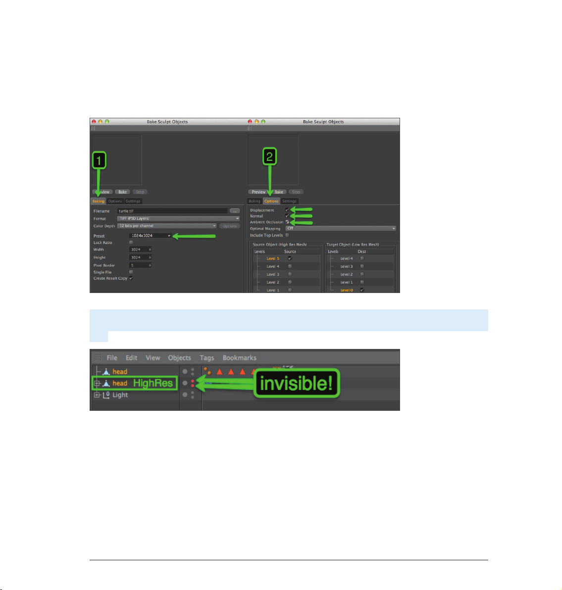
This completes our turtle’s sculpted head! Baking an object that contains objects with millions of polygons
can reduce the number of polygons to a manageable amount and will produce exactly the same result for
rendering! Baking generates Displacement and Normal textures that, simply put, subdivides the geometry
during rendering and lets you work with low-res objects in the Viewport while maintaining filigree details for
rendering. Baking will not affect the sculpted surfaces. To bake your object, click on the Bake Sculpt Object in
the Sculpt Palette and use the settings shown in the next image:
After all settings have been made, click on the Bake button. Before rendering the Project, make sure that the
original object is hidden so you don’t end up rendering both the high-res and the low-res object at the same
time.
Even though this tutorial used an existing object as a basis for sculpting, you can also begin with a simplesphere,
for example, and create fantastic objects using the Sculpt tools in BodyPaint 3D. After making the sphere, or
any other Primitive, editable (C key), there’s practically no limit to what you can sculpt.
55Sculpting
Page 60

© Kornel Ravadits
© Simon Hellwig © Kevin Capizzi
Sample Images56
Page 61

© Toni Ramon Sanchez
© Josh Grundmeier – www.fuseanimation.com
Sample Images 57
Page 62

BodyPaint 3D R16
Quickstart-Handbuch
Die in diesem Handbuch beschriebene Software unterliegt den Lizenzbedingungen der MAXON Computer GmbH und darf
© 2014 MAXON Computer GmbH • All rights reserved
Max-Planck-Str. 20 • 61381 Friedrichsdor f • Germany • Tel. +49-(0)6172-5906-0 • Fax +49-(0)6172-5906-30
MAXON is Part of the N emetschek Group • www.maxon .net
 Loading...