

Page 1
Quickstart
Page 2

BodyPaint 3D R15 Quickstart
The software described in this document is subject to a license agreement and may only be used in accordance
with the regulations thereof.
Programming Christian Losch, Philip Losch, Richard Kurz, Aleksander Stompel, Tilo Kühn,
Per-Anders Edwards, Sven Behne, Wilfried Behne, Thomas Kunert, David O’Reilly,
Paul Everett, Cathleen Bastian, Ole Kniemeyer, Kent Barber, Jens Uhlig, Frank Willeke,
Sebastian Rath
Plugin programming Michael Breitzke, Kiril Dinev, David Farmer, Jamie Halmick, Reinhard Hintzenstern,
Jan Eric Hoffmann, Eduardo Olivares, Nina Ivanova, Markus Jakubietz,
Eric Sommerlade, Hendrik Steffen, Jens Uhlig, Michael Zeier, Matthias Bober,
Markus Spranger, Michael Kloß, Ralph Reichl, Timm Dapper, Paul Everett,
G.E.M. Team Solutions, Michael Welter, Eberhard Michaelis
Product management Bernd Lutz, Oliver Meiseberg
Quickstart writers Glenn Frey
Layout Aron Schmid, Kai Perschke
Translation Scot Wardlaw, Luke Stacy
Copyright © 1989–2013 by MAXON Computer GmbH all rights reserved.
This manual and the accompanying software are copyright protected. No part of this document may be translated, reproduced,
stored in a retrieval system or transmitted in any form or by any means, electronic or mechanical, for any purpose, without the
express written permission of MAXON Computer. Although every precaution has been taken in the preparation of the program and
this manual, MAXON Computer assumes no responsibility for errors or omissions. Neither is any liability assumed for damages
resulting from the use of the program or from the information contained in this manual. This manual, as well as the software
described in it, is furnished under license and may be used or copied only in accordance with the terms of such license. The
content of this manual is furnished for informational use only, is subject to change without notice, and should not be construed as
a commitment by MAXON Computer. MAXON Computer assumes no responsibility or liability for any errors or inaccuracies that
may appear in this book.
The trademarks [MAXON] (DE 1 139 896, CTM 4639191, IR 950 459; registered in the European Union, the Russian Federation
and Australia), [CINEMA 4D] (DE 2 068 89 1, CTM 4959698, IR 66 4 160, JP 4 385 968, KR 40-2008- 0033230; registered in
the European Union, Switzerland, the Russian Federation, USA, Japan, South Korea and China), [MAXON FORM] (CTM 4518569;
registered in the European Union) and [MoGraph] (CTM 4926771; registered in the European Union) are registered trademarks of
MAXON Computer GmbH. In addition, trademark rights can exist for MA XON Computer GmbH or MAXON Computer Inc. in various
territories for the aforementioned or other trademarks, e. g. BodyPaint 3D, RayBrush and C.O.F.F.E.E.
Acrobat, the Acrobat logo, PostScript, Acrobat Reader, Photoshop, Flash and Director and Illustrator are trademarks of Adobe
Systems Incorporated registered in the U. S. and other countries. Apple, AppleScript, AppleTalk, ColorSync, Mac OS, QuickTime,
Macintosh and TrueType are trademarks of Apple Computer, Inc. registered in the U.S. and other countries. QuickTime and the
QuickTime logo are trademarks used under license. Microsoft, Windows, and Windows NT are either registered trademarks or
trademarks of Microsoft Corporation in the U.S. and/or other countries. UNIX is a registered trademark only licensed to X/Open
Company Ltd. All other brand and product names mentioned in this manual are trademarks or registered trademarks of their
respective companies, and are hereby acknowledged. HDRI material preview: Creative Market.
Bullet Time is a registered trademark from Warner Bros. Entertainment, Inc.
The information in this document are subject to change without notice.
I
Page 3
BodyPaint 3D R15 Quickstart ______________________________________________________________________________________________ I
BodyPaint 3D R15 Standalone Part 1
____________________________________________________________________________ 1
1. Introduction ___________________________________________________________________________________________________________________________________ 1
2. General Information/Interface
3. Quick Tutorial: First Painting Lesson
4. BodyPaint 3D UV Edit
__________________________________________________________________________________________________________________ 10
5. BodyPaint 3D Exchange Plugin
6. Tips and Tricks
_______________________________________________________________________________________________________________________________ 22
___________________________________________________________________________________________________ 2
________________________________________________________________________________________ 6
__________________________________________________________________________________________________ 19
BodyPaint 3D R15 Standalone Part 2 ________________________________________________________________________ 24
1. Introduction ___________________________________________________________________________________________________________________________________ 24
2. General Information/Standard Layout
3. Quick Tutorial: Materials
4. Quick Tutorial: Light
5. Quick Tutorial: Rendering
______________________________________________________________________________________________________________ 30
_____________________________________________________________________________________________________________________ 36
____________________________________________________________________________________________________________ 42
_____________________________________________________________________________________ 24
Sculpting ______________________________________________________________________________________________________________________________________________ 46
Note:
As a result of continued product development, differences between the current and printed documentation
with regard to referenced files can occur. The most current versions can be found on the product DVD
included in your order, or can be downloaded from the MAXON website or via the Online Updater.
II
Page 4

BodyPaint 3D R15 Standalone Part 1
Core functions
In this tutorial we will explain the most important functions in order to give you a running start in the world
of “body painting“. Even if BodyPaint 3D appears to be difficult at first, you will soon notice how intuitive
BodyPaint 3D really is. In this tutorial we have also put an emphasis on a fast learning curve and a high
degree of user friendliness for this. This standalone Quickstart tutorial manual is made up of two parts. Part
1 contains the core functions and Part 2 explains additional functionalities. In this Quickstart manual you will
be asked to open certain files for demonstration purposes. These can be found on your Goodies DVD or on the
MAXON homepage on the download/documentation page
1. Introduction
To make working with this Quickstart easier, instructional text and tips have been underlain with color for
easy recognition.
Instructional text is highlighted in blue.
If you make an error in working through one of the tutorials, these colors will make it easier to locate
instructional text and tips when trying to find the location at which you may have made the error.
BodyPaint 3D uses “Dark” as its standard layout. Of course you can select a different layout (main menu: Edit/
Preferences/Interface/Scheme), if desired.
BodyPaint 3D will revolutionize the way you work with textures in such a way that you will wonder how you
ever got along without it! With this you can paint your models as they are: in 3D. This is what BodyPaint 3D, the
revolutionary way to texture objects, is all about. In addition, BodyPaint 3D lets you paint in several texture
channels at once, and thanks to RayBrush even directly on the rendered image itself. Projection Painting is a
tool we have integrated that makes it possible to paint on complex objects without distortion.
Using the UV tools you can relax and stretch your UV mesh, no matter how complex it is. Put simply, a UV
mesh is a second impression of a polygon mesh that projects the texture onto a polygon object. The days of
2D texturing are over and you can finally concentrate on what’s important in texturing: Creativity. Everything
that took up so much time with 2D texturing is now done by BodyPaint 3D and you can deliver your projects
faster. Let’s move to the user interface. (BodyPaint 3D is a component of CINEMA 4D and can be activated by
simply selecting BodyPaint 3D from the CINEMA 4D Layout menu at the top right of the GUI)
ENGLISH
1Standalone Quickstart
Page 5
2. General Information/Interface
BodyPaint 3D Standalone offers many functions that will again speed up and improve your workflow. Let’s
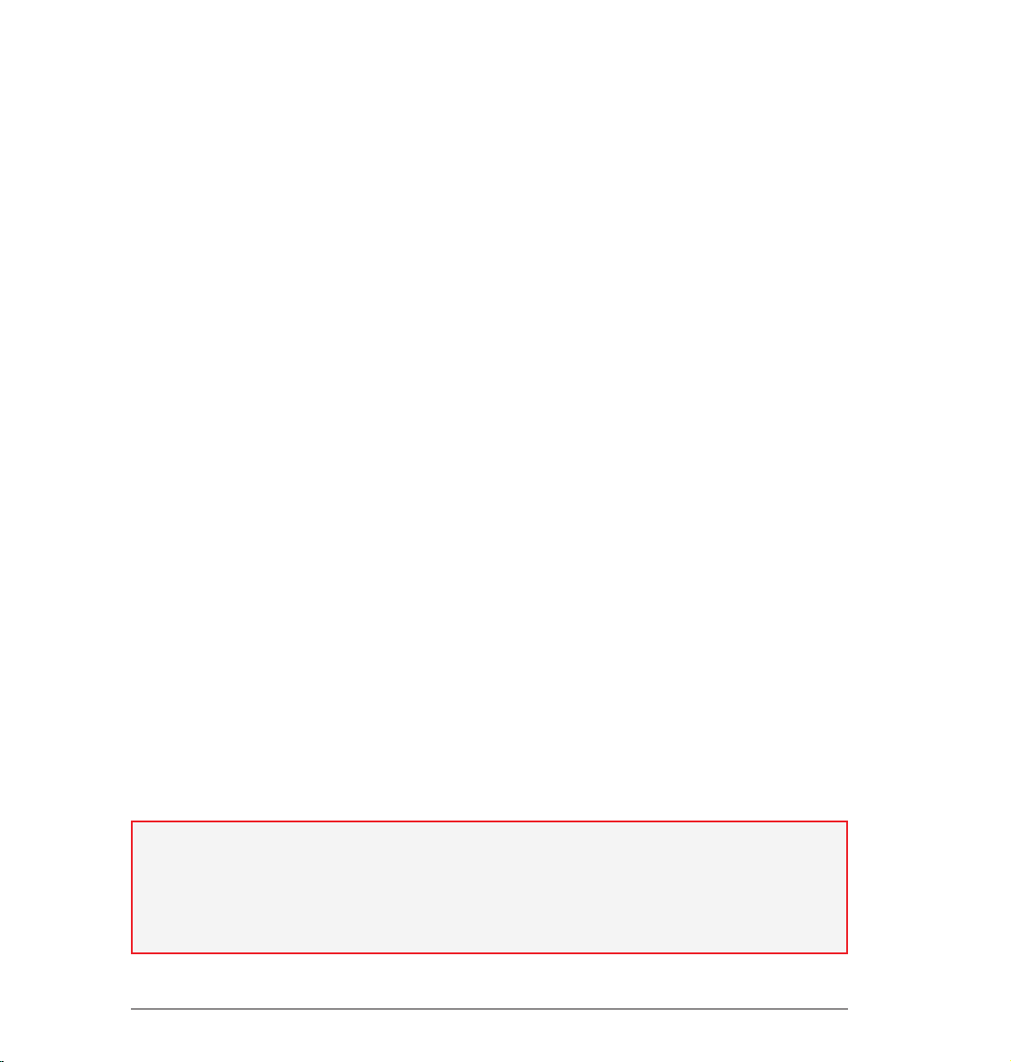
start with the most important step - starting BodyPaint 3D. After starting BodyPaint 3D you will see an image
similar to the following screenshot:
6. Icon Palette
(modes)
5. Object Manager
and color settings
1. Rendered Viewport
4. Attribute Manager Window
2. Texture Window
(UV Mesh Editor Window)
3. UV Manager
Here you see one of the two standard layouts: BP UV Edit. The second layout (BP 3D Paint) is set up in a similar
fashion, only without the UV mesh editor window which gives you more room in the editor window to paint.
2
Standalone Quickstart
Page 6

1. Viewport
Here you can see the object you will be painting. You can rotate, move and zoom the window as needed. The
RayBrush mode lets you paint directly onto the object in the rendered version of the view. This gives you
control over the amount of color applied and can see right away how a new color looks on the object.
2. Texture Window (UV Mesh Editor Window)
This is where you edit your UV mesh. You can relax and restore your UV mesh. If you use the UV Manager’s UV
tools you can watch how the texture relaxes. You can also watch the color application process in this window,
which will then be visible in the editor window right away.
3. UV Manager
The UV Manager lets you restore the UV mesh using an algorithm. It recognizes layered polygons and attempts
to relax the UV mesh for optimal placement over the entire surface and, if necessary, new placement. All
remaining “relaxation“ can be adjusted manually.
4. Active Tool Window (Attribute Manager)
Different tabs display different brush types and their respective attributes as well as the UV Manager’s UV
tools.
5. Object Manager and color settings
We’re sure we don’t have to say much about the Object Manager. It’s the same manager as in the CINEMA 4D
main program and lets you select the object to be edited or change its position in the hierarchy.< This is the
CINEMA 4D Material Manager with expanded functionality. This is where you will find your textures with their
respective layers. If needed, you can paint in several layers at once (for example color and relief channels). To
do this simply select the texture to be painted and the respective layer and start painting.
ENGLISH
6. Icon Palette
The command palette contains the Paint Setup Wizard, the Projection Painting and many other tools (that
you are probably used to using with 2D paint programs). The Paint Setup Wizard eliminates the need to
manually create a texture including the UV mesh. It also calculates the texture size and channels. Without
these bothersome preparations you can begin painting right away.
3Standalone Quickstart
Page 7
© Peter Bucholz
© Joe Yan – dr_heyjoe@hotmail.com © Anders Kjellberg – www.dogday-design.com
4
Sample Images
Page 8

Now we’ll get to the heart of this tutorial. Open the file QS_BP3D_01.c4d. Say hello to Claude, our guinea pig
for the day. In the course of this tutorial we will alter the color of his right eyelid a little and apply a bump layer
in elephant-look to his skin. Select the predefined standard layout BP UV Edit at the top right and to the left
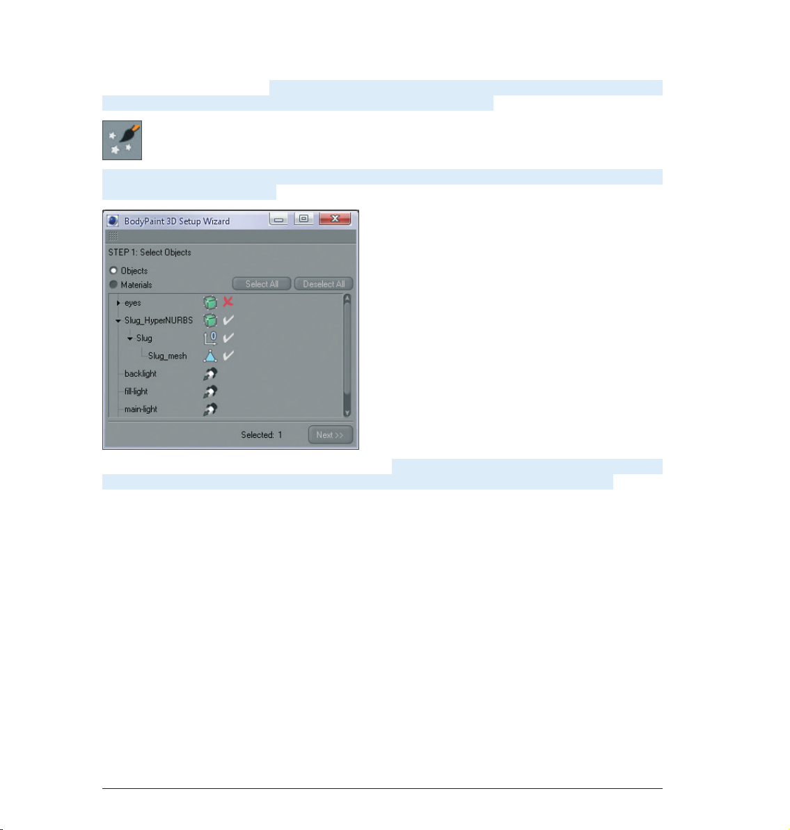
of BodyPaint 3D´s main editor window. Click on the Paint Setup Wizard Icon so we can make the necessary
preparations to the texture (brush icon with white stars).
Click on Deselect All in the window you just opened and apply a white check mark to the “eyelid right“ object
only.
We have just determined that a texture should be created only for the right eyelid object. Click on Next. Leave
the settings in the next window the way they are. The selection Single Material Mode would create a texture
for each object individually. If the box is not checked all objects will share one texture surface. Click on Next
again. In the next window check the bump channel. The color channel is selected by default. You can double
click the little gray boxes next to each texture channel and assign each channel a base color. Since Claude
likes elephant gray we will leave the boxes the way they are. Leave the rest of the settings the way they
are and click on Finish, then on Close in the next window. The basic textures have been created and we can
start painting. If you have experience with earlier texturing methods and the time it took to even get started
BodyPaint 3D will seem like a blessing to you. BodyPaint 3D saves you a lot of time. Now let’s move to the
second part of the tutorial: the UV meshes and the first brush stroke.
ENGLISH
5Standalone Quickstart
Page 9
3. Quick Tutorial: First Painting Lesson
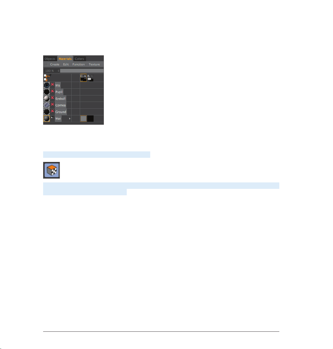
At the bottom left of the Material Manager (in the Materials tab) you will find the texture we just created, right
next to Mat.
This is the default name for a new texture. Of course you can rename the texture if you like. The first material
is the color layer and the second is the bump layer (at the top of the window you will see the abbreviations
which refer to these layers – C for color and B for bump).
Now Select the Use UV Polygon Edit Tool symbol.
Once you have selected the corresponding texture in the color channel the UV mesh should become visible in
the texture window at the upper right. If the mesh is not visible, activate it by clicking on UV Mesh/Show UV
Mesh in the texture window menu. Luck is on our side! The UV mesh looks good. The only thing that bothers
us is the fact that the edges of the eyelids are too small (highlighted in orange in the next image!).
6
Standalone Quickstart
Page 10
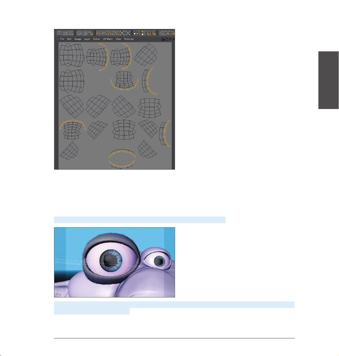
The individual UV mesh polygons of these eyelid edges take up less texture area than the rest of the polygons.
That’s why a texture placed into the bump channel appears larger in these places (photograph of elephant
skin, for example). We can do without this, though, since we are painting our own skin structures onto the
surfaces and not using an existing texture. We can counter any distortion we encounter when painting
manually by using Projection Painting. The stroke will maintain its width no matter how the polygon is spread
over the mesh.
Move and zoom the editor window view until Claud’s right eyelid fills the view.
ENGLISH
Now select Brush Tool for Painting Textures for applying the color. Set the size to 25 and the hardness to 40
in the brush’s Attributes Manager.
7Standalone Quickstart
Page 11
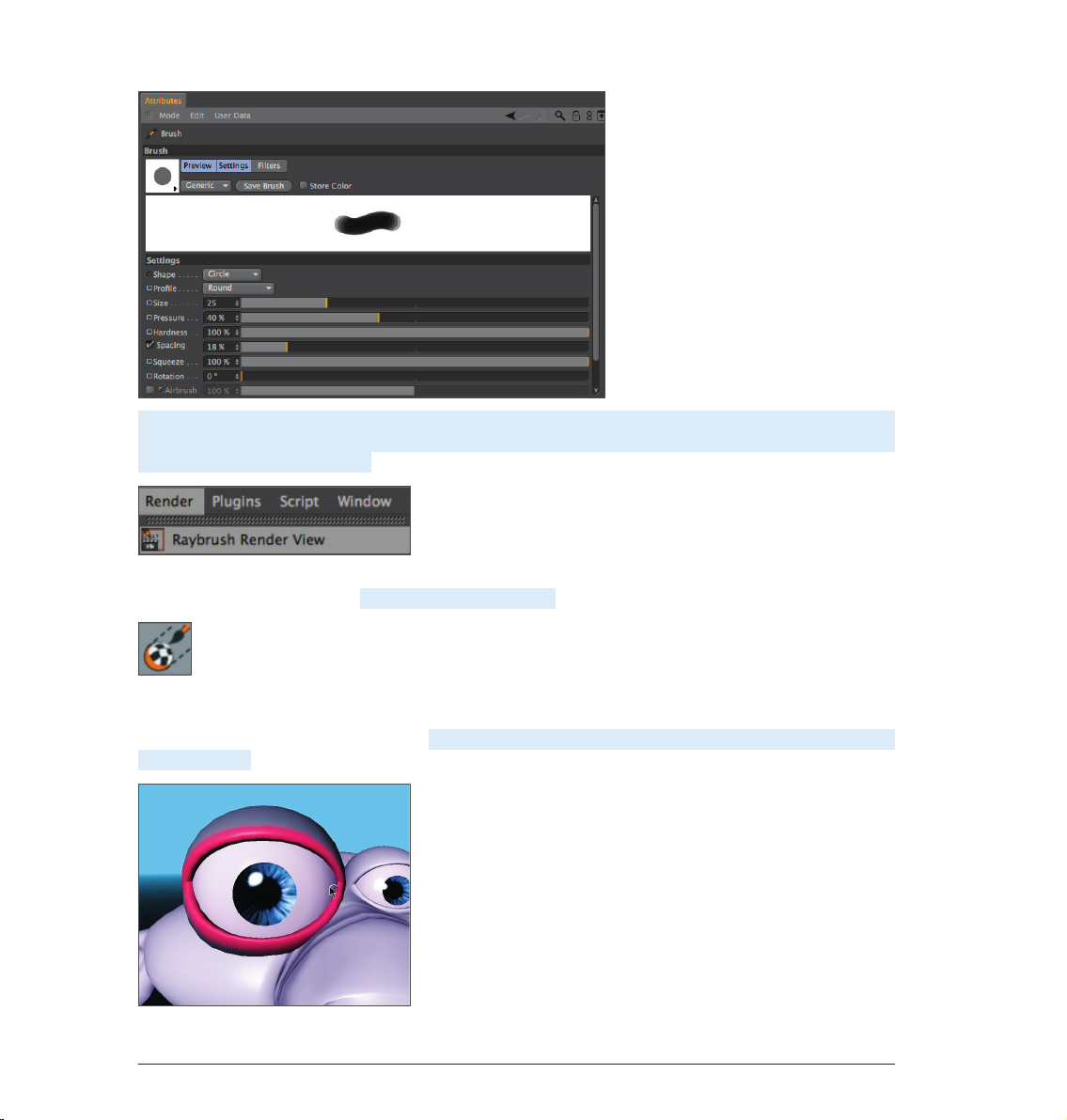
...and select a pink color using the Preview Active Channel directly below. If necessary, increase the Subdivision
Surface subdivision. Activate the Render Active View for RayBrush Painting in the active view in the Render
menu (BodyPaint 3D main menu).
(This will render the view and makes it possible for you to control the color application and the look of the
strokes for the final rendering). Activate Projection Painting
(You already know what this function does) and start painting. Of course BodyPaint 3D supports the use of
graphic tablets such as a WACOM Intuos. Painting objects with a pressure sensitive pen on a graphic tablet is
much easier than painting with a mouse. Paint along the edge of the eyelid. The eyelid will probably end up
looking like this:
8
Standalone Quickstart
Page 12
If you move/rotate the figure now or click on the Apply the Content of Projection Paint Plane
you will see how the color was applied to the texture (you can see the recently applied strokes of color in the
window to the right).
You can take the same steps for the bump layer. We will take you one step further, though, in order to be able
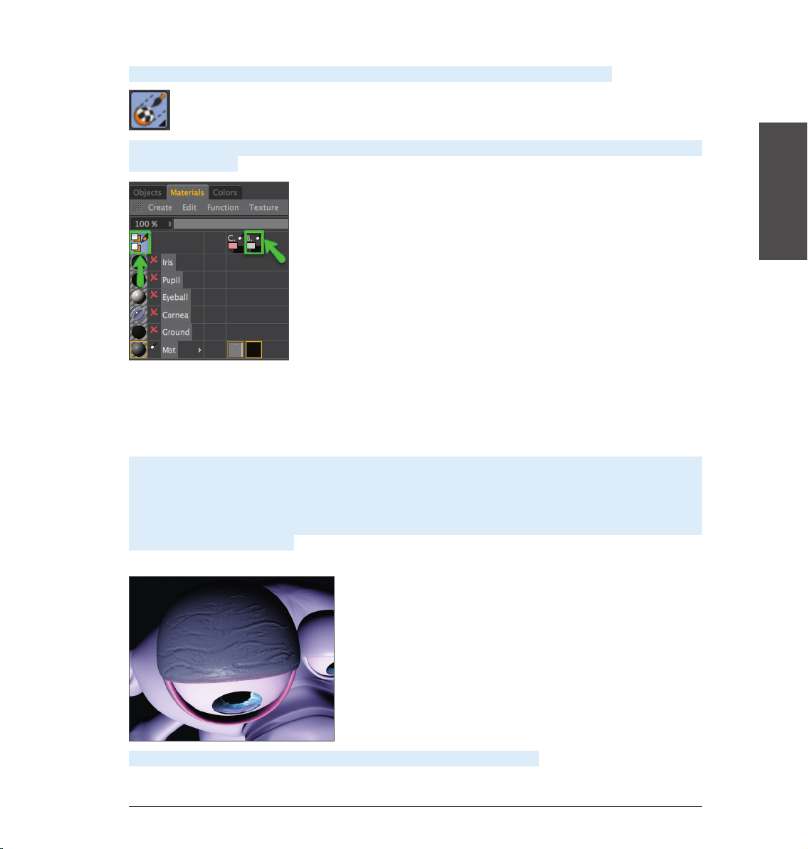
to explain an important function. We will paint both eyelids at the same time! Select the texture in the color
channel of the Material Manager. Now click on the icon with the black/orange pencil at the left of the Material
Manager. A light blue background tells you the multi-brush mode is active. Select the pencil icon next to the
B of the bump channel as well..
Rotate the view so you can see the eyelid from the top. Activate the Render Active View for RayBrush Painting
mode and set the brush size to 10. Switch to the color layer’s Color menu and set the color to a medium gray
which will be the base color for our eyelid. Now go to the bump layer’s color preview and set the color to black
(both color layers are located in the Materials tab under the letters C and B + pencil symbol). When you paint
on the object you will notice that both colors are being applied to the object – the gray base color and the
black (to indicate indentations). (If white were the color of the Bump channel it would “raise” the brush stroke
instead of indicating indentations). The result could look like the following image.
ENGLISH
Load the QS_BP3D_01_Final.c4d file and take a look at it when you have time.
9Standalone Quickstart
Page 13
4. BodyPaint 3D UV Edit
In this chapter we will show you more about editing UVs. First, though, you need to know what UVs are before
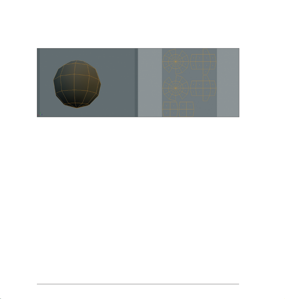
getting started. Take a look at the following screenshot:
The polygons of the sphere at the left are outlined in orange. Now imagine the sphere has a second invisible
skin lying over the polygon mesh. We will cut this skin open at selected locations and press it flat onto a
surface. This is our UV mesh (at right). This UV mesh is nothing more than a copy of our polygons in a flat state.
The UV mesh can be edited independently of the polygon mesh without affecting the polygons’ geometry and
vice-versa.
Each individual polygon has a UV counterpart with which it is linked, however each can be edited independently
of the other. This only applies to the shape of our polygons with regard to UVs and not, for example, to the
coloring. If part of a texture on which a UV lies is painted, the polygon linked to that UV will automatically
receive the same color. Hence, the mesh on the right can be painted and the result can be seen immediately.
Inversely, the sphere on the left can be painted and the result can be seen on the mesh to the right as the
painting occurs. Hopefully the basic function of UVs is now clear to you. Now you may be wondering how UVs
are edited and, more importantly, why.
We have created another screenshot (below) in order to better demonstrate this. What you should know first,
though, is that UV meshes aren’t always as neat and clean as the one used above, especially when working
with complex objects. The UV polygons of complex objects can often overlap when opened and flattened
(BodyPaint 3D does this for you automatically). Individual UV polygons can also be scaled oddly. Make sure
UV polygons do not overlap, causing them to share textures. If, for example, a hot pink were used to paint the
lips of a character and the UV polygons belonging to the lips overlapped with a few of the polygons belonging
to the side of the character’s neck, the hot pink color would be applied to these UV polygons as well. Unless
you’re designing an alien politician who talks out of the side of his neck this would probably be an unwanted
effect.
10
Standalone Quickstart
Page 14
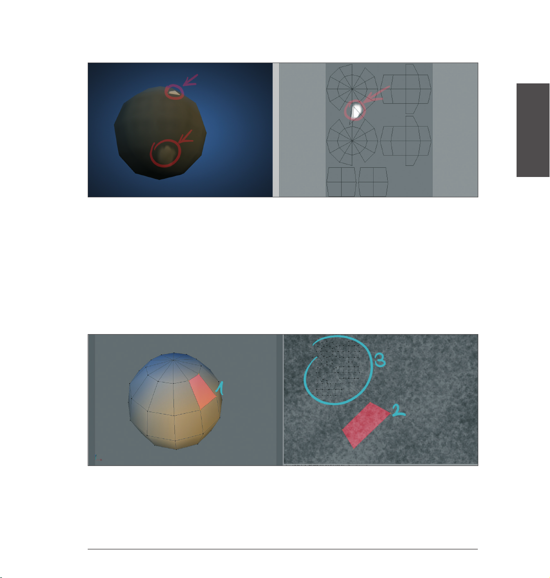
Now for our screenshot to clear things up:
At the right you can see the UV mesh with the underlying texture. We have added a white spot to the texture.
If you look closely you will see that two UV polygons overlap. This means that they share the same area of
the texture in the area in which they overlap. This result in the white spot being displayed twice on our sphere
(left). This can be quickly remedied by manually moving the UV polygons or points or by applying BodyPaint
3D’s Relax UV function. More on that later, though.
Once the UV polygons no longer overlap the next issue to avoid arises:
If, for example, a noise bump texture is used that should appear uniformly on a given obect, the UV polygons
should have more or less the same size. If a few UV polygons are much larger than the rest, the noise bump
texture would appear much finer on those larger surfaces.
Of course we have created corresponding screenshots to demonstrate this effect.
ENGLISH
11Standalone Quickstart
Page 15
We have highlighted a polygon (red) on the sphere at left. At right you can see the corresponding UV polygon,
also highlighted in red. In order to clearly demonstrate what happens when a particular polygon is much
larger than the rest, we have greatly reduced the size of the surrounding UV polygons. Take a close look at the
right side of the UV mesh. The highlighted UV polygon takes up much more space then the surrounding UV
polygons. However the size of the corresponding polygons remains the same. Accordingly, the texture’s noise
will be squeezed onto the size of the respective polygon when rendered, resulting in a finer noise texture.
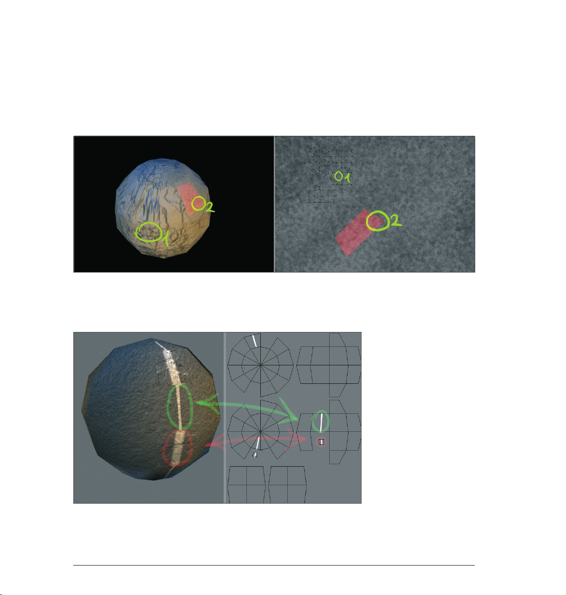
This can be seen clearly in the following screenshot:
Caption: The circled areas of our UV mesh on the right and the corresponding areas on the sphere (left).
The texture in area 1 is much more coarse than the texture in area 2. This is because the UV polygon of area
2 is much larger, causing the bump to be displayed much finer. A further example of the effect large UV
polygons have when applying color:
12
Standalone Quickstart
Page 16
In the scene above we scaled down two UV polygons and subsequently drew a white line on our sphere from
top to bottom. You can see how the line width varies depending on the size of the UV polygons. The impression
is made that two different line strengths were used when painting, even though only a single line was drawn.
So what should you do if you paint your artistic stripe onto the sphere with a constantly varying brush strength
and the UV polygons also vary in size?
Answer: Use the newly integrated Projection Painting tool. You will find the icon in the Command Palette.
This intelligent little tool keeps the brush thickness from being varied and makes sure that the line is applied
equally onto the object. The artistic stripe you painted will be varied in width only on the texture under the
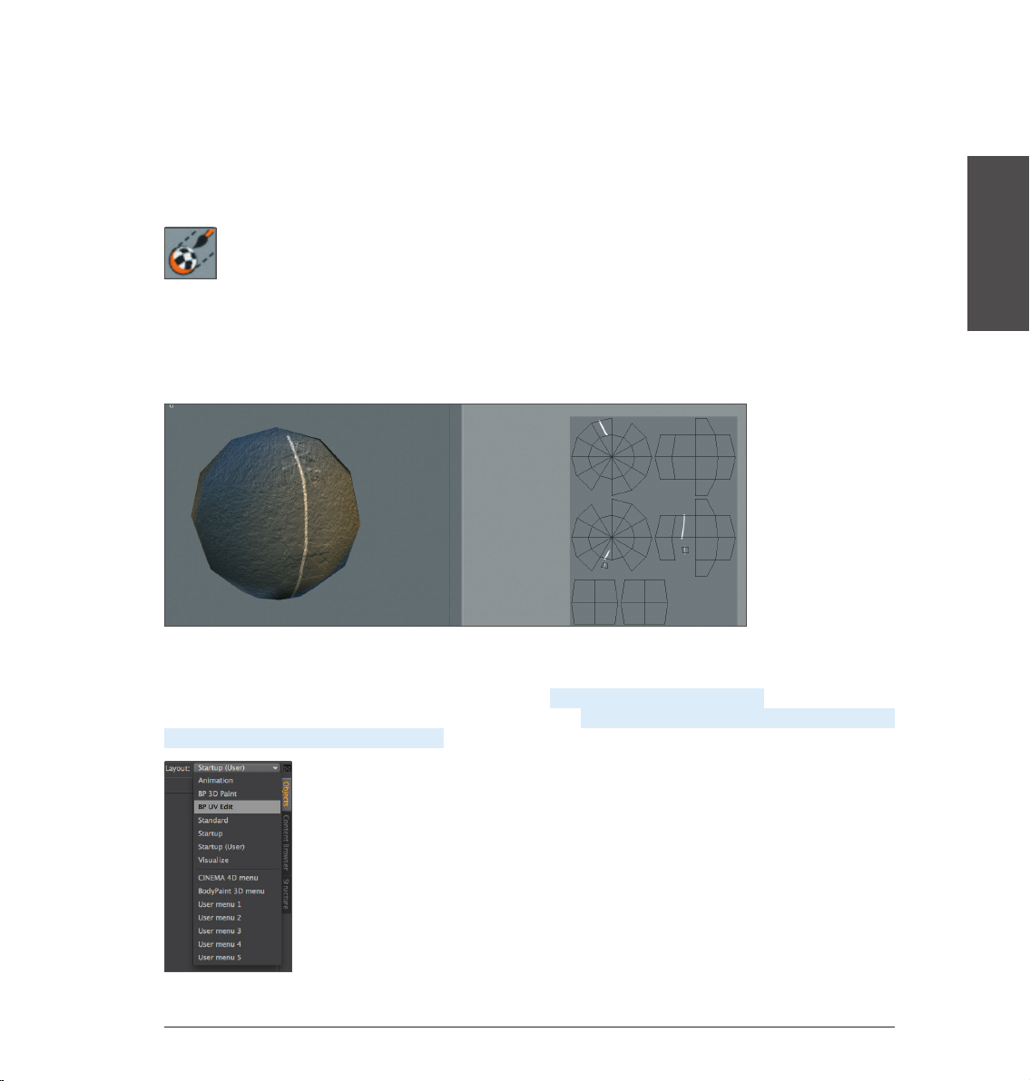
UVs. The line in the next screenshot was painted using Projection Painting. Take a look at the different line
strengths on the UV mesh at the right. At those locations where the UVs are small the line width will be
narrower as well.
ENGLISH
It is very important that you understand this basic concept when working with BodyPaint 3D in order to
achieve optimal results.
In the following we will take a closer look a the UV tools. Open the file QS_BP3D_02.c4d. This file contains a
snail’s head whose UV polygons we will prepare for painting. Start by switching to the default layout BP UV
Edit at the top left right of your interface.
13Standalone Quickstart
Page 17
We have just switched to BodyPaint 3D’s UV edit inter face. The functions contained in this layout are specifically
designed for the editing of UVs. Next we will create a material with the corresponding UV polygons. To do so
click on the Paint Setup Wizard tool, located in the Command Palette above.
In the window that appears, click on the top white check mark and subsequently click on the Next button twice,
once on Finish and once on Close.
We have just created a texture for the Color channel. At the right you should now be able to see our UV
polygons. If not, activate the Show UV Mesh option in the menu from that window’s UV Mesh menu.
14
Standalone Quickstart
Page 18
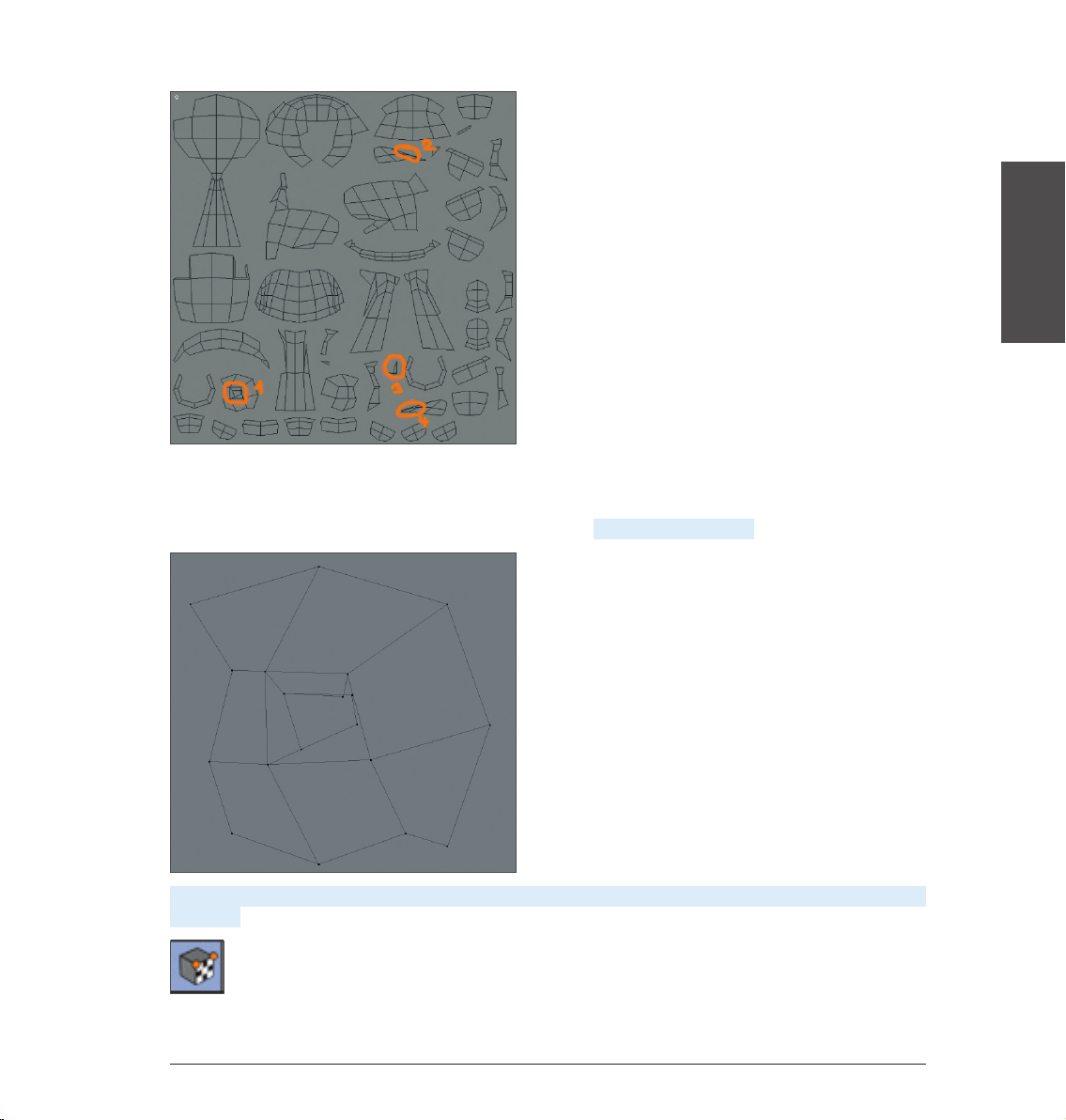
The Paint Setup Wizard saves us from having to manually peel the UV skin off of our character and has
flattened it neatly onto our texture. Our mesh looks quite good at first glance. However, if you look closely,
a few spots can be found that need working on, which we have circled for you in orange. Areas 1 and 2 have
overlapping and the polygons in areas 3 and 4 are too small. First, zoom in to area 1.
ENGLISH
As you can see, two UV polygons overlap in the center. In order to correct this, first activate the Use UV Point
Edit tool...
15Standalone Quickstart
Page 19
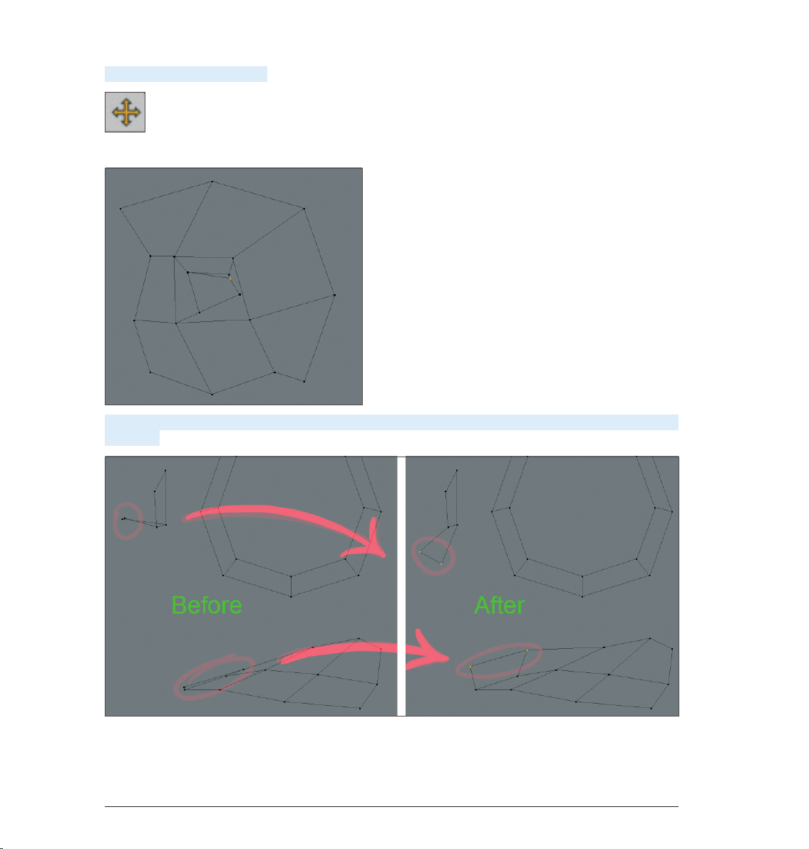
...then activate the Move tool...
...and rearrange the corresponding points until the UV polygons no longer overlap.
The remaining areas (2-4) can also be corrected using this method. Refer to the following screenshots if you
need help:
16
Standalone Quickstart
Page 20
Once all problem areas have been corrected the mesh can be painted. The method we just described was the
manual method of fixing such problem areas. However, BodyPaint 3D also offers tools that will automatically
“relax” complex UV polygons and we will turn our attention to these tools now. Open the file QS_BP3D_03.
c4d. The geometry in the area of the monkey’s missing nose is perfect for our demonstration (note that no
animals were hurt in making this tutorial. All animals are trained virtual professionals!).
If not already there, switch to the BP UV Edit layout.
ENGLISH
Start the Paint Setup Wizard...
...and click twice on Next, once on Finish and finally on Close. As in our first example, you will see the UV mesh
appear in a window at the right of your interface. Select the Use UV Polygon Edit tool from the Command
Palette at the top and open the UV Mapping tab in the UV Manager at the bottom right of your interface. Once
in the UV Mapping tab, go to the Projection page.
17Standalone Quickstart
Page 21
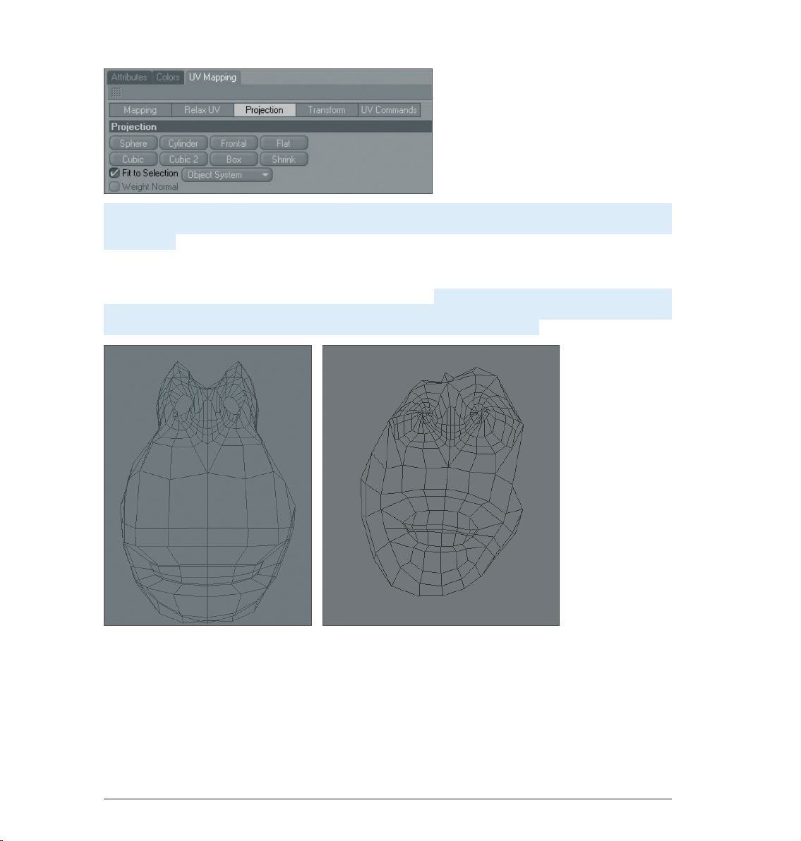
Set Projection to Frontal. Now select other types of projection by clicking on the corresponding button to
see the different types of projections that are available. Once you’ve taken a look at them all, switch back to
Frontal mode. Frontal mode reflects the active editor view. This is also why we have chosen this mode for our
monkey’s face.
As you can see, the UV polygons in the area of the monkey’s nose are overlapping. We will now use the
BodyPaint 3D Relax UV tool to take care of this little problem. Open the Relax UV page in the UV Manager’s
UV Mapping tab. On this page you will see an Apply button. Make sure to deactivate the Pin Border Points and
Pin To Neighbors options and click on Apply. The UV mesh will be markedly relaxed.
Left: Before applying Relax UV. Right: After applying Relax UV.
Each UV polygon now lies next to another and no UV polygons overlap. Doing this manually would have
practically been impossible and may even have led to a few nervous breakdowns among our readers. That’s it,
our UV mesh is now ready to be painted. As you can see, just a few steps are required and you can turn your
attention to the creative part of your work - painting your object’s UV mesh.
18
Standalone Quickstart
Page 22
5. BodyPaint 3D Exchange Plugin
Before we get started we want to pass on some important fundamentals to you.
By default, BodyPaint 3D saves images in .tiff format, which can also contain layers. When these images are
subsequently loaded and re-saved in foreign applications, these layers may be lost. If you use Photoshop for
editing your images you can also set your BodyPaint 3D default image format to .psd (Photoshop).
The files BodyPaint 3D requires to communicate with foreign applications (e.g. Maya, 3ds Max, XSI or LightWave
3D) can be found in the BodyPaint 3D program folder under “Exchange Plugins” or on our web site at www.
maxon.net in the Downloads section. Make sure you copy all necessary files for the applicable software to the
corresponding directory. If using Maya the files must be loaded and executed in the following order using the
Script Manager: BodyPaintExchangeLoadPlugin.mel; BodyPaintExchangeUI.mel; usersetup.mel. (refer to your
BodyPaint 3D reference manual for additional information).
For Maya, the object exchange, including textures, is done using the corresponding menu command.
(Please refer to the BodyPaint 3D reference documentation (Main menu/Help) for information regarding the
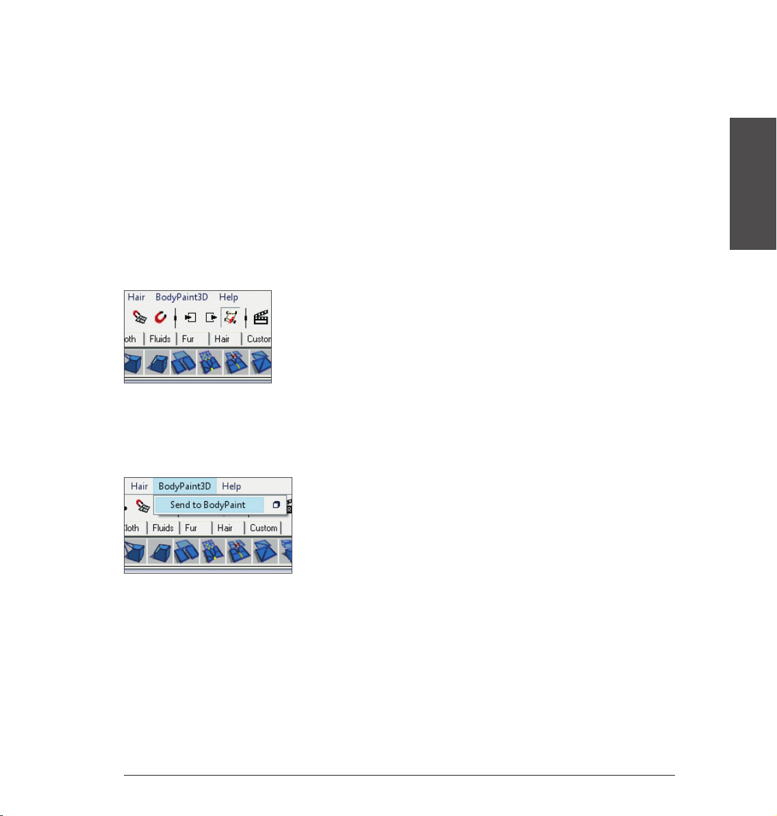
location of the corresponding BodyPaint 3D exchange plugin for your software). Exchanging objects is very
easy. Take an object, send it to BodyPaint 3D using the Send to BodyPaint command (BodyPaint 3D will be
started automatically), paint your object in BodyPaint 3D and send it back to your application using the Send
Scene Back command.
ENGLISH
Geometry-, material-, light-, UV- and any available texture data will be exchanged. Your BodyPaint 3D
reference manual provides more information regarding the preparation of files for use with exchange plugins.
The following information applies to use with Maya:
19Standalone Quickstart
Page 23

MAC
[Maya 5]
Macintosh HD / Applications / Alias Wavefront / maya 5.0 / maya
• Right-click on the Maya executable file and select Show Package Contents.
The path will be the following: Contents / MacOSClassic / plug-ins.
• The scripts belong here: Macintosh HD / Users / Shared / Alias / maya / scripts.
[Maya 6]
Macintosh HD / Applications / Alias / maya 6.0 / maya
• Right-click on the Maya executable file and select Show Package Contents.
The path will be the following: Contents / MacOS / plug-ins.
• The scripts belong here: Macintosh HD / Users / Shared / Alias / maya / scripts.
[Maya 6.5]
Macintosh HD / Applications / Alias / maya 6.5 / maya
• Right-click on the Maya executable file and select Show Package Contents.
The path will be the following: Contents / MacOS / plug-ins.
• The scripts belong here: Macintosh HD / Users / Shared / Alias / maya / scripts.
[Maya 7]
Macintosh HD / Applications / Alias / maya 7.0 / maya
• Right-click on the Maya executable file and select Show Package Contents.
The path will be the following: Contents / MacOS / plug-ins.
• The scripts belong here: Macintosh HD / Users / Shared / Alias / maya / scripts.
20
Standalone Quickstart
Page 24

PC
[Maya 5]
• Plugin: C: \ Programs \ AliasWavefront \ Maya5.0 \ bin \ plugins
• Scripts: C: \ Documents and Settings \ username \ My Documents \ maya \ 5.0 \ scripts.
[Maya 6]
• Plugin: C: \ Programs \ Alias \ Maya6.0 \ bin \ plugins
• Scripts: C: \ Documents and Settings \ username \ My Documents \ maya \ 6.0 \ scripts
[Maya 6.5]
• Plugin: C: \ Programs \ Alias \ Maya6.5 \ bin \ plugins
• Scripts: C: \ Documents and Settings \ username \ My Documents \ maya \ 6.5 \ scripts
[Maya 7]
• Plugin: C: \ Programs \ Alias \ Maya7.0 \ bin \ plugins
• Scripts: C: \ Documents and Settings \ username \ My Documents \ maya \ 7.0 \ scripts
In contrast to MacOS, Maya scripts must be installed for each user separately in Windows.
ENGLISH
21Standalone Quickstart
Page 25

6. Tips and Tricks
• A very helpful function can be found in BodyPaint 3D’s preferences (Ctrl+E). In the BodyPaint menu you will
find the function Project On Invisible Parts. Which, when activated, can make your work a lot easier. Let’s
assume you want to color the arm of a figure or sprinkle color on the entire figure. You would have to apply
the color with this function deactivated, rotate the arm, apply the color, rotate the arm and, well, you get
the idea. When this function is activated you apply the color in the front view and the color is applied to all
surfaces lying behind this surface at the same time. Just make sure you don’t apply color to objects you
don’t want to color when this function has been activated.
• If a texture map does not fit correctly at the point where large and small polygons meet (in the case of
low-poly objects that are subordinates of Subdivision Surface) set the Tile UVs function, in the respective
Subdivision Surface Object’s Attributes Manager, from User to Border or Edge. This sends the UV mesh
through the Subdivision Surface algorithm and subdivides it to fit the polygon object. Make sure the
Subdivision Surface type is set to Catmull-Clark (without N-Gons). Otherwise this function will be disabled.
• Avoid UV polygons that meet to a point when applying a noise texture to a bump layer. The narrower a
3-sided polygon becomes, the coarser the bump noise channel will be rendered. Of course such a polygon
has much less area for the noise structure at its tip than it does at its center which results in a magnification
effect of the noise structure. Try to set up each side of a triangulated polygon as an isosceles. This also goes
for “4-point polygons“ when they converge into a trapezoid. The more square the polygon the more even
the structure will be.
• It goes without saying that you need different brushes for different texture looks. BodyPaint 3D has a wide
variety of brush types for you to use. Just select the brush Tool and click on the small black arrow on the
brush preview.
• Here you will find all the brushes your heart desires. If you don’t find the brush you’re looking for we’ve beat
Murphy to the punch and have given you the possibility to create and save your own brushes. Just make the
changes you want and click on the Add Preset Save Brush button.
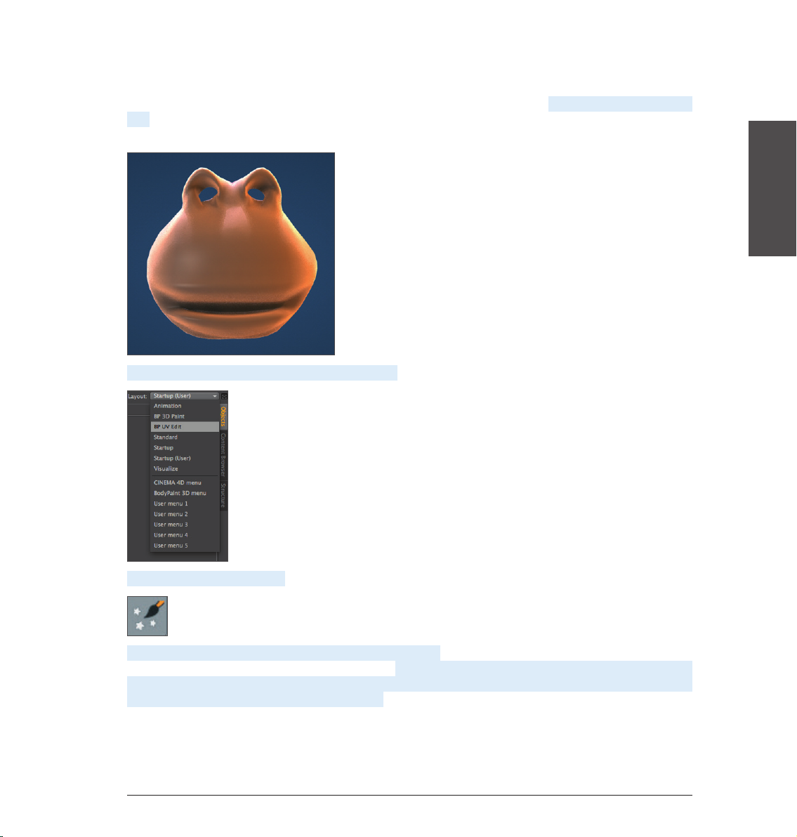
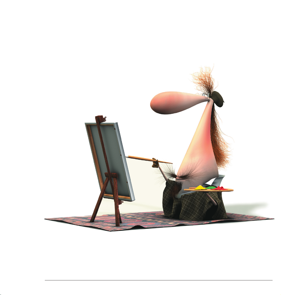
• With this tutorial you have gotten to know how BodyPaint 3D works and you can convince yourself of the
advantages painting directly onto objects themselves offers. With only a little practice you can also achieve
similar results as you can see on the next image – Claude’s new texture outfit.
22
Standalone Quickstart
Page 26
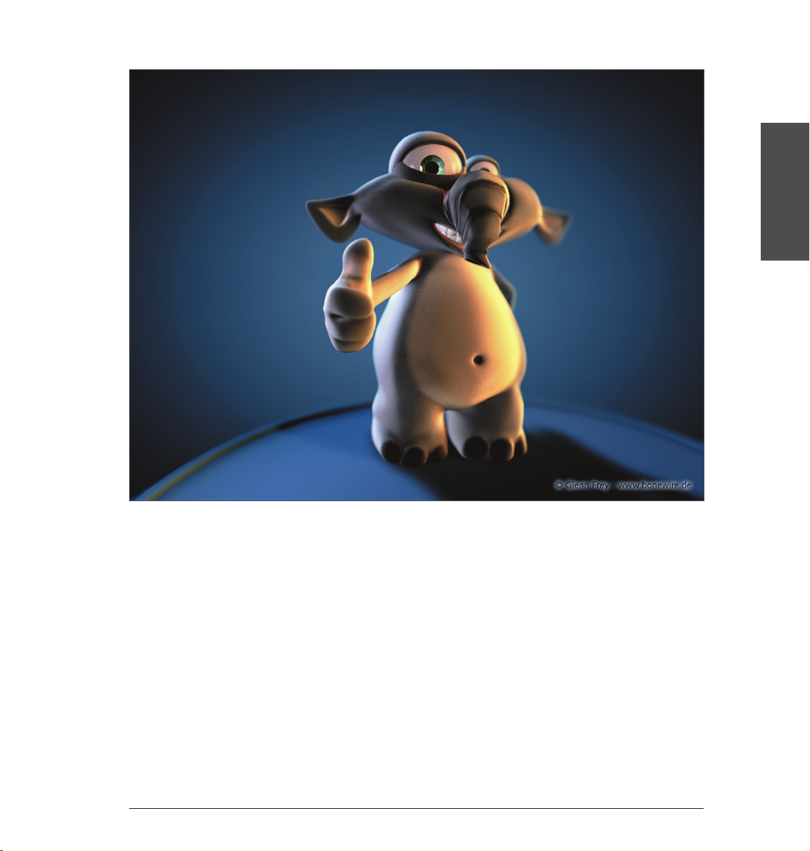
Here the same rule applies for best results: Try it, don’t just study it!
ENGLISH
23Standalone Quickstart
Page 27
BodyPaint 3D R15 Standalone Part 2
Additional functions
1. Introduction
The purchase of BodyPaint 3D R15 Standalone lets you do more than just paint objects. With it you can also
model, texture, animate and set lights. We will explain a few of these core functionalities in the following
tutorials.
No matter if you work in the field of print, advertising, design, visualization or film, BodyPaint 3D gives you all
the tools you need to make your ideas reality. In order to give you an impression of what to expect from the
interface we’ll go straight to Part 2 of the BodyPaint 3D standalone Quickstart tutorial – the standard layout.
2. General Information/Standard Layout
Rendered Viewport
Icon Palette
(modes)
Viewport
(perspective view)
Icon Palette (tools)
Material Manager Coordinates Manager
Object Manager
Attribute Manager
24
Standalone Quickstart
Page 28
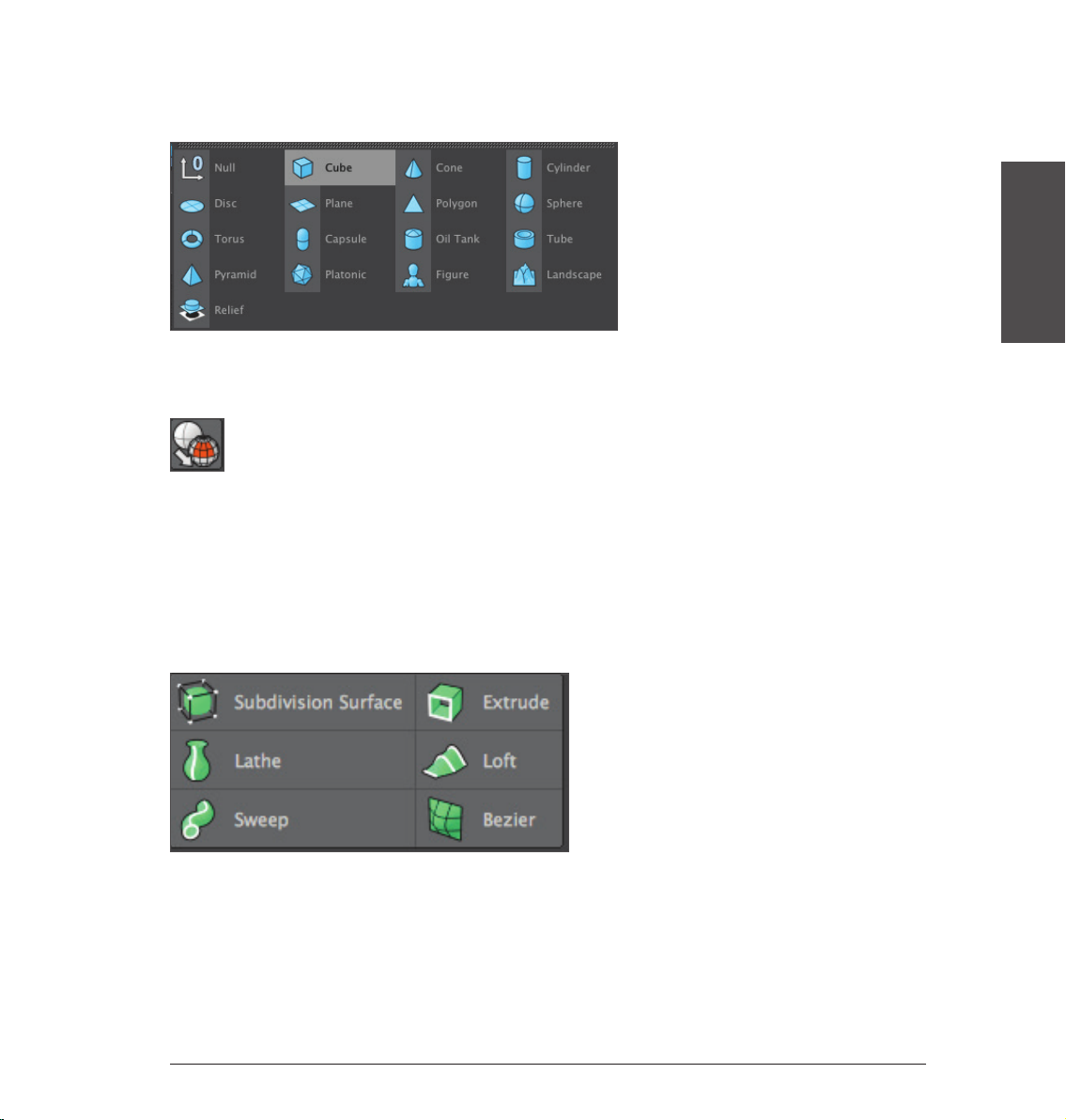
The primitives are located in the Primitives command group. It contains all of BodyPaint 3D’s available
predefined parametric objects.
One click and the world’s most used object is created – the cube. Click and hold to see all available parametric
objects. This is where you choose the initial shape you will need. And don’t forget that only parametric objects
that have been converted to polygon objects can be edited at a polygon, point or edges level!
Note: After an object has been initially created it is basically a parametric object. A parametric object can only
be modified as a whole and not its individual surfaces (an exception are special deformers from the Deformer
menu). Before you begin modeling, the parametric object must be converted to a polygonal object. To do
so, select the object you want to convert and run the Make Editable command by pressing the c-key on your
keyboard. You can now move or modify individual points and surfaces. Two symbols to the right of the Cube
Primitive symbol (black cage with white points and turquoise inner) are the Generators. The most important
of these is the Subdivision Surface object.
The next group icon hosts probably the most important BodyPaint 3D object, the Subdivision Surface object.
ENGLISH
25Standalone Quickstart
Page 29
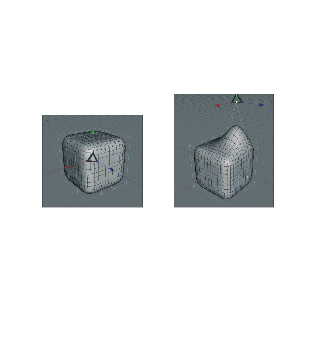
If a polygon object is a Child object of a Subdivision Surface object its polygon wire frame (mesh) will be
subdivided to a higher degree. If an object is made a Child of a Subdivision Surface object its subdivisions
will be increased virtually, which will give the object a softer look. As you can see in the next screen shot:
The outer mesh (light blue) shows the polygon cube’s actual subdivision. The finer inner mesh (blue) shows
the subdivision of the Subdivision Surface object. Change the cubes’ display mode by selecting (deactivating)
Options/Isolines in the Viewport’s menu and switching to Gouraud Shading (Lines) in the Editor’s Display
menu. In the end it’s up to you how you want your objects displayed in the same menu. Then switch to the
Use Polygon Mode in the left Icon Palette. However, for this tutorial, this is the most effective way to show the
effect Subdivision Surface objects have on polygonal objects or primitives since it shows how the cubes are
subdivided and the final result is therefore also easier to visualize.
The advantages, especially in modeling, are obvious. Since the object contains few points (edges / polygons)
that can be edited it remains very manageable. You can drag just one point of the original wire frame and
the Subdivision Surface mesh, with its finer subdivision, will follow the virtual point being dragged (see next
screenshot).
If the polygon object were made up of such fine subdivision modeling, it would be much more complicated.
You would pull one point and only one point would be moved. All other surrounding points would retain their
position. You would have to move each one individually in order to achieve the desired shape.
26
Standalone Quickstart
Page 30
© Bill Ledger – ToyBox Animation
Sample Images 27
Page 31

© Kevin Capizzi
© Anders Kjellberg – www.dogday-design.com
28
Sample Images
Page 32

© Anders Kjellberg – www.dogday-design.com
Sample Images 29
Page 33

3. Quick Tutorial: Materials
A well-modeled object can make a mediocre impression if the right textures aren’t used. Textures give a model
color, highlights, structure and other important surface properties. A texture placed into the bump channel,
for example, gives the object’s surface an uneven, bumpy look without actually altering the geometric
structure. This effect can be used to imitate skin wrinkles, scars or the surface of an orange. The displacement
channel works in a similar fashion, only that it actually does change an object’s geometric structure. Using
the luminance channel you can give an object’s surface a self-illuminating property or integrate a Subsurface
Scattering effect (SSS) which lends the surface a slight translucent/reflective look, like human skin or candle
wax, for example. In short: Textures have the same significance as the outer shape of an object because they
are necessary for achieving the desired atmosphere, coloring and surface structure.
We will begin with a brief introduction to the individual material channels:
Color: This is where the material’s color or the base color for the texture is set.
Diffusion: This channel makes your texture “irregular“. Through the application of a noise shader
or a texture your object receives a dirty or dusty look. If desired it can also influence the specular,
reflection and luminance channels respectively.
Luminance: The material is given an illuminative property which is also taken into account in the
radiosity Global Illumination calculation.
Transparency: This is where you determine the material’s opacity.
Reflection: Gives the material a reflective characteristics.
Environment: A material is used to simulate an environment reflection.
Fog : This channel lets you apply a fog or cloud property to a material.
Bump: Uses an optical trick to translate light and dark elements of a texture or a shader to simulate
the height and depth of an uneven surface. Scars, wrinkles or scratches can be simulated using this
channel.
Normal: This channel is meant for use with “normal textures”. Normals give a low-res polygon object a
hires look when RGB textures containing the required properties are applied. This lets a hi-res polygon
object be replaced by a low-res object, thus saving a lot of render time and offering the same visual
result.
Alpha: A texture’s transparency is determined by a material’s light and dark areas. Black equals a
transparency of 100 % and white makes it opaque.
Specular: This determines a material’s specular properties.
Specular Color: This determines the color of the material’s specularity and can be influenced by a
texture.
Glow: Gives the object a self-emitting glow.
Displacement: Deforms an object using light and dark values (calculates differences in height). Do not
confuse this with the relief channel which only imitates an uneven surface.
30
Standalone Quickstart
Page 34

We will now create our own material. Open the QS_Material.c4d file. You can see in the Object Manager to
the right that the object does not yet have a texture applied to it. Click on file/new material in the Material
Manager at the lower left.
A standard material has been created. If you click on this material its properties will be made visible in the
Attributes Manager to the right. In the Basic menu you can determine which channels should be activated for
this material. Go ahead and activate the Bump channel. As soon as you have done that a new menu button,
Bump will appear. Now click on the menu button Color and load a texture into the material by clicking on the
small arrow next to Texture. Choose Load Image and load Iristexture.jpg. In the mini-preview of the Material
Manager at the lower left of your screen you will see the texture displayed as soon as it has been loaded. This
gives you a good overview of the materials being used in the scene.
ENGLISH
Repeat this procedure for the Bump channel and load Iristexture_bump.jpg into the channel. This JPEG
contains the gray scale version of the iris texture which we need to create a relief effect for the surface. You
can also choose Filter (click on the small light gray arrow next to the word Texture in the Bump channel) and
load the color texture here and set its saturation to 100 %. This saves you from having to load a second image.
The bright areas of the image will later appear to be raised on the object and the dark areas of the image will
appear to be somewhat indented. A true deformation of the object will only take place in the Displacement
channel. The Bump channel does not alter the polygon’s surface but uses an optical illusion to give the surface
its structure.
31Standalone Quickstart
Page 35

Click on the material in the Material Manager with the left mouse button and drag it onto the object eyeball
in the Object Manager. (When you drag the material over the object you can let go once the little white arrow
points down). Alternatively you can drag the material onto the desired object (the eyeball) directly in the
Editor. Just make sure you drop the material onto the correct object if there are several in the scene or in
close proximity to one another. You can check in the Object Manager to make sure the material was dropped
onto the correct object - the material icon will appear next to the object onto which it was dragged.
You have probably noticed that the eyeball brightened somewhat after you applied the material but you aren’t
able to see the actual texture. We still have to change the offset properties and the mapping size so the
texture will be aligned properly on our object. At the moment the actual image of the iris is lying distorted on
the right side of the eyeball. You can check this by making both Subdivision Surface eyelid objects invisible for
the editor. To do this double-click on the top small gray dot to the right of the object in the Object Manager
(until it turns red).
Double-click on the dot again and it will turn green, which makes the objects visible again independent of the
visibility settings of any parent object. The dot directly below has the same function except that it affects the
rendering. Once you have made the eyelids invisible and have rotated the view a little the eyeball should look
as follows:
Switch the visibility of the Subdivision Surface objects back by clicking again on the dots next to the object in
the Object Manager, making them gray. Click on the Texture Tag at the right of the Object Manager next to the
object. It’s the material that we applied to the eyeball. You can recognize it in the mini preview of the texture
in the Object Manager.
32
Standalone Quickstart
Page 36

Once you have selected it you will see its parameters in the Attributes Manager. Adopt the settings you see
in the next screenshot:
We have just aligned the texture on the eyeball mesh by changing the Length U and Length V parameters. The
offset setting put the texture in the correct position. If you rotate your view again you will see that the iris
texture is positioned correctly.
ENGLISH
Tip: If you want to undo an accidental change to the view just press Cmd+Shift+Z (Mac: Cmd+Shift+Z). This
function is useful if you have inadvertently rotated the perspective view instead of the editor view. You can also
select edit/undo view in the main menu of the editor view. The texture will complete our model. Experiment
with the parameters of the individual channels to find out how they affect the material. At this point we would
like to offer you a few additional tips.
33Standalone Quickstart
Page 37

If you own CINEMA 4D Visualize or CINEMA 4D Studio you can render human skin, for example, very realistically
using Subsurface Scattering. The shader Surface Scattering makes it possible. By placing this shader in the
luminance channel (click on the small arrow next to Texture and select Subsurface Scattering from the Effects
menu/Subsurface Scattering) the effect is created when rays of light meet a slightly transparent object.
Some rays infiltrate the object further and are dispersed, others are directly absorbed or bounce off. Further
possible uses for this effect would be for materials such as plastic, milk, candle wax or figurines made of jade.
You can load black-and-white textures into the alpha channel to influence the material based on the texture’s
brightness, similar to the way you would use them for the bump or displacement channels. The texture’s black
areas would be rendered with a transparency of 100 %. As the texture becomes brighter the transparency is
reduced accordingly. White would have a transparency of 0 %
If you choose Shader instead of New Material under create in the Material Manager you will see a list of shader
presets. The advantage of these shaders is that you don’t have to worry about mapping your texture or seams
in your texture because a 3D shader will be calculated for the 3D space. Here are a couple described in detail:
Cheen: Generates an electron microscope effect. Danel: Very good for simulating high-gloss finish
34
Standalone Quickstart
Page 38

Banzi: Lets you depict various types of wood.
Banji: Calculates complex lighting situations with glass and even makes rear-projection (shadow casting) on
partially transparent materials such as rice- or canvas paper possible.
ENGLISH
35Standalone Quickstart
Page 39

4. Quick Tutorial: Light
If you are already familiar with lighting a scene in the real world then you will feel right at home with the
BodyPaint 3D light objects. They can do everything real lights can do – and quite a bit more. In this tutorial
we will set up a 3-point lighting arrangement. This type of arrangement is used often in portrait photography
to achieve an even lighting and is an excellent method for lighting an object quickly and professionally in the
3D world Open a new (empty) scene. Create a floor object Create/Environment/Floor). Our little amphibian
man will be our lighting victim. Merge the file, QS_Light.c4d into the scene (Main menu: File/Merge). Adjust his
position so he’s standing on the floor. Adjust your editor view so the entire figure is visible to you.
A 3-point lighting arrangement begins with setting a key light. As the name suggests, this light emits the
main lighting for the scene and will cast the main shadows. Create a light object (Objects/Scene Create/Light/
Light). Name it Main_Light (double-click on the name) in the Object Manager.
BodyPaint 3D has several different types of light sources. The key light will always be created by default. A
point light emits from its center in all directions. For our key light we will need a spot light which we can aim
directly at the object. To make the key light a spot simply go to the Attributes Manager and switch the light
from Point to Spot.
36
Standalone Quickstart
Page 40

Now our light source has been transformed to a spot. A spot acts like a flashlight. BodyPaint 3D offers spots
with square and round cones of light. This cone is visible in the editor and can be manipulated. Now we will
aim the spot at our figure.
Position the light at the following coordinates in the Attribute Manager:
X= 300
Y= 580
Z= –300
at an angle of
H= 45
P= –45
degrees (enter the values and click on the Apply button).
Render the scene (Cmd/Ctrl + R).
ENGLISH
37Standalone Quickstart
Page 41

The light now falls at an angle onto our object (If this is not visible in the Editor it may be due to the fact that
your display mode is set to Quick Shading (uses a single default light source) instead of Gouraud Shading (uses
all scene lights)). Of course the exact position of the light is strongly dependent upon the camera’s angle.
Unfortunately the light is not casting a shadow, letting the figure look like it’s floating. CINEMA 4D’s lights
have an advantage over real light in that you can choose which kind of shadow, if any, they should cast - a plus
for any studio photographer. In the General menu of the Attributes Manager, set the light’s shadow to Shadow
Maps (Soft). We don’t want the shadow to be completely black so we’ll make it a little transparent.
In the Shadow menu, set the shadow density to 50 %. Select 1000 x 1000 as the shadow map. Render the
scene.
38
Standalone Quickstart
Page 42

BodyPaint 3D offers three types of shadows: RayTraced (Hard) – a shadow with sharp edges, Shadow Maps
(Soft) – a shadow with soft edges and Area – a shadow that becomes softer the further it’s away from the
object, resulting in the most realistic shadow effect. Try the other two shadow types. Careful, the area shadow
can take a long time to render! The larger shadow map allows the shadow to be rendered more accurately.
The light’s cone is a little too small. We will change this as follows:
Switch to the details menu in the Attributes Manager and set the Inner Angle to 30 degrees and the Outer
Angle to 100 degrees.
You will see the result in the editor right away. You can also edit the light’s cone by dragging the orange
handles (If your graphics card will support it you can set the editor’s display mode to Enhanced OpenGL with
activated shadows. (Viewport: Options/Enhanced OpenGL) Generally speaking, OpenGL offers a much more
precise depiction of your scene and gives you an impression of how the shadows will fall).
ENGLISH
39Standalone Quickstart
Page 43

Now we’re happy with our key light. Next we will create a more even lighting by brightening our figure a little
from the other side.
Create another light source in the scene and name it “Brightener”. Place it at the following coordinates:
X= –360
Y= 225
Z= –230
Select Area as the type of light.
Since the brightness of the lights in the scene is additive, we must “dim“ the brightener a little.
Reduce the Intensity in the General menu to 40 %.
This area light illuminates the figure from a different angle and softens the contrast somewhat. It won’t cast a
shadow since this would cause “crossing“ of the shadows and make the object look bad.
40
Standalone Quickstart
Page 44

The scene is now pretty evenly lit, but we want to give it a little more pep. Create another light source, name
it Color and, in the Attributes Manager, set its type to Infinite. Set its color to turquoise and set its H angle to
–160. The position of an infinite light is irrelevant since it always lights your scene in the direction of the Z axis.
This is why we will leave it at the point at which it was created. It gives our Amphibian an interesting color edge
and sets him off of the background a little.
Your scene’s mood can be changed by simply changing the color of some of the lights used.
ENGLISH
That completes our classic 3-point lighting arrangement. Now the real work starts. If the scene has a
background, which is often the case, it will have to be lit as well. With the proper use of point lights details in
the scene can be “brought to light“ very nicely. But don’t overdo it. With good lighting, less is often more. Only
add lights when necessary and if the scene can actually benefit from them. Two more tips before we end: If you
have several lights in a scene and are not sure which light is lighting what, simply turn off (green check mark)
all other lights in the Object Manager. The light which remains will be the only one visible.
There is a trick how you can determine how to best light which objects in your scene. Select the desired light in
the Object Manager and activate Link Active Object in the editor view’s Cameras menu. Selecting this option
lets you view the scene from the point of view of an active object, in our case the light. Moving the editor view
will automatically change the position of the light when in this mode. This way you can see how the change of
position of the light affects the lighting of the object in realtime (Gouraud Shading must be active in the editor
view). Once you have reached the desired angle and position you can return to the editor view by selecting
Editor Camera from the Cameras menu.
41Standalone Quickstart
Page 45

5. Quick Tutorial: Rendering
You’ve been a busy bee. You have created a scene, set up the lighting, animated objects and assigned materials
to them. Now we want to see the result of all this work. What you have to do is to transform this 3-dimensional
scene into a 2-dimensional image (in the case of an animation it would be an entire series of images). We will
“render“ the images. Open the file QS_Render_01.c4d to work through the following tutorial. BodyPaint 3D
offers a wide variety of options for rendering your 3D scene.
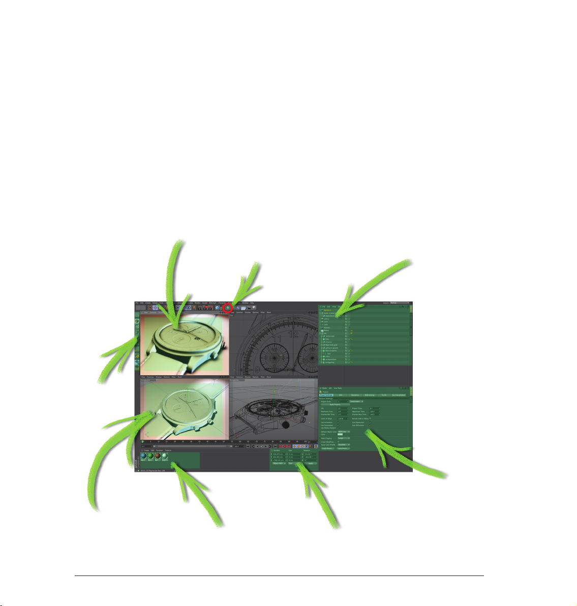
1. Using the main menu
2. The keyboard shortcut Ctrl+R
3. By clicking on the icon in the editor window
Use the method with which you feel most comfortable.
42
Standalone Quickstart
Page 46

Often we don’t necessarily want to render the complete editor view but only a small part of it. This is also no
problem. Select Render/Render Region. The cursor will be transformed into a cross. Drag a frame around the
region you wish to render.
The second possibility is to render only a single object.
Select the object “Master” in the Object Manager. Select the command (Render/Render Active Objects).
ENGLISH
Only the selected objects will be rendered. Rendering the editor view gives us a quick overview of the scene
but it does not offer the possibility to process this image further, to save it to the hard drive, for example.
Select “Render”/“Render to Picture Viewer” or press Shift+R. What good is the best rendering if you can’t
save the images it generates? Of course there is a command with which you can do this. Select Render/
Render to Picture Viewer or press Shift+R. The picture viewer will open in a separate window in which the
scene will be rendered. When the image has been rendered select File/Save Picture As. A further window will
open. Select the appropriate format and confirm with OK.
43Standalone Quickstart
Page 47

Of course you can also save a series of images as an animation. To do so, change the Type from Still Image to
Selected Frames, and set Format to QuickTime Movie, for example. Rendering to the Picture Viewer has the
additional advantage that you can continue working on your scene if the image should take a while to render.
Close the picture viewer and open the Render Settings (Render/Edit Render Settings).
You use the Render Settings to determine what our final image will look like Everything from size, quality,
single image or animation can be set here. Render the image again in the editor window and take a closer look
at the result. It looks a little pixelated. You can see a similar effect along the edges of the object. This is called
“anti-aliasing“. This term refers to how smoothly an edge has been rendered.
44
Standalone Quickstart
Page 48

Set Anti-aliasing to “None“ in the “Render Settings“.
The effect is much worse without anti-aliasing. Set anti-aliasing to “Best“ and render the scene again. All
edges have been rendered sharp as a knife without being pixelated.
ENGLISH
© Fredi Voss
45Standalone Quickstart
Page 49

Sculpting
Welcome to the Quickstart sculpting tutorial. With the introduction of BodyPaint 3D R15, a powerful new
sculpting tool is available to users and offers comprehensive organic modeling features. In this tutorial we will
show you how to get started with the BodyPaint 3D sculpting tool. We will show you how to create the object
in the image below.
At the left is the base object. It contains practically no details and looks quite bland. On the right side is the
same object after being modified using the Sculpt tools. The comprehensive toolset makes it possible to
create incredibly detailed surfaces. After you complete this tutorial we encourage you to experiment with the
various tools to see what they can do.
Since this is an introductor y tutorial whose aim it is to show users the basic sculpting functions in BodyPaint 3D,
we will only sculpt the head.
Before we get started and to help inspire you to higher heights, let’s take a look at a finished version of our
turtle in its entirety.
46
Standalone Quickstart
Page 50

ENGLISH
© Augenpulver – http://www.augenpulver-design.de/
47Standalone Quickstart
Page 51

Open the file ‘Sculpting_Turtle.c4d’.
At the top right of your interface, select Sculpting from the Layout drop-down menu.
To begin sculpting we must first select and subdivide the object. Click on the Objects tab at the right of the
Object Manager. Attention: If you start with a primitive object instead, you need to convert it in a polygon
object first (with the object selected press „c“ on your keyboard).
Select the object ‘head’ in the Object Manager. Make sure that you are in Use Model mode in the left Icon
Palette. If not still there, switch back to the Sculpting Layers tab in the Object Manager.
Next, click on the Subdivide button 6 times. The first click transforms the polygon object into a Sculpt object
and automatically assigns a Sculpt tag to the object. The first click will give the mesh a sculpting Level of 0.
Each additional click will subdivide the mesh further. After 6 clicks your mesh should have a Subdivide level of
5 (the Subdivision level is displayed in the Sculpting Layers tab’s Level field). Although the wire frame display
is useful for polygon modeling it can be a hindrance for sculpting because of the high level of subdivision. To
make the surface visible, select the Pull brush and press the W key on your keyboard. This will disable the
wire frame display. Any brush stroke we make can be undone by simply selecting Undo. Generally speaking,
a graphics tablet is better suited for sculpting than a mouse because it lets you control your strokes more
precisely.
48
Standalone Quickstart
Page 52

We will now add a Sculpt Layer to our base object. In the Sculpting Layers tab, select Add Layer from the
Layers menu. Next, select the Pull brush and switch to the Stencil tab in the Attribute Manager. Drag the
texture Turtleskin.png from the ‘tex’ sculpting project folder into the Stencil tab’s Image field. Alternatively
you can click on the button at the right of the Image field and select the texture from the dialog window.
ENGLISH
© Dimitris Katsafouros
49Standalone Quickstart
Page 53

The Stencil you just selected will appear in the Viewport. You can adjust its transparency in the AttributeManager as you see fit but a value of 0.5 is a good value with which to start. Enable the Tile X and Tile Y
options in the Attribute Manager (Stencil tab). This ensures that the Stencil will be applied across the object’s
entire surface. Finally, we have to adjust the Stencil’s size. The structure applied by the brush is always in
relation to the size of the Stencil/object. This means that you can adjust the Stencil size as well as the camera’s
distance from the object to apply a larger or smaller structure. The Stencil will always lie perpendicular to
the camera’s angle of view, no matter how you position the camera. Scale the Stencil to reflect the size in the
image below by using the Attribute Manager’s Scale setting or by using the combination T + RMB until you
achieve the desired size. In the brush’s Settings menu, set Size to 50 and Pressure to 20 %.
Next, switch to the side view in the Viewport, make sure that you are on Layer 1 in the Sculpting Layers tab,
and paint across the turtle’s head with the brush. Apply the Stencil using different perspective views and
make sure that you only change the camera’s angle of view to the object and not its distance from the object.
Otherwise the Stencil will be applied in different sizes. When you’re finished, press the Q key to hide the Stencil
(and again to make it visible).
50
Standalone Quickstart
Page 54

Tip: If you use a graphics tablet you can click on the fx button at the right of the Size or Pressure setting to link
the respective function to the pressure-sensitive behavior of your pen. Your turtle’s head should look similar
to the image below when you’re done.
ENGLISH
Leave the Stencil size as it is and zoom in on the object. Use the image below as a reference.
51Standalone Quickstart
Page 55

Reduce the brush size to 10 and paint over the lip and eye lid regions. The result should look like this:
In the next step we will apply a Mask. Click on the Mask button at the bottom of the Sculpt Palette. Add a new
Layer as you did before, leave the Size value set to 10 and set Pressure to 5 %. Make sure you are on Layer 2
and paint across the turtle’s neck to create a surface similar to the one in the image below.
Tip: Pressing the Ctrl key while painting will delete the Mask; pressing the Shift key while painting will smooth
abrupt transition. The same applies to the sculpting process: Pressing the Shift key while sculpting will apply
a smooth sculpting effect.
52
Standalone Quickstart
Page 56

Next, click on the Invert Mask button in the Sculpt Palette and then select the Pull brush. Set the brush’s Size
to 50 and its Pressure to 5 %. Paint across the surface of the head as you did before. You will notice that only
those regions not affected by the Mask are modified by the Pull brush.
Smoothing tip: While smoothing the folds along the throat we don’t want the structure on Layer 1 to be
affected. This can be prevented by simply hiding Layer 1 for the duration of the sculpting process.
ENGLISH
53Standalone Quickstart
Page 57

The final result should look similar to the image below:
We will apply one additional brush to complete our turtle’s head: The Knife brush. Delete the Mask by clicking
on the Clear Mask button in the Sculpt Palette. Alternatively you can simply hide the Mask in the Sculpting
Layers tab, which will make it available for future use. Add a new Layer and select the Knife brush. Set its
Pressure to 10 % and its Pinch value to 0.25. Paint along both sides of the nose to create a ridge as shown in
the image below.
54
Standalone Quickstart
Page 58

This completes our turtle’s sculpted head! Baking an object that contains objects with millions of polygons
can reduce the number of polygons to a manageable amount and will produce exactly the same result for
rendering! Baking generates Displacement and Normal textures that, simply put, subdivides the geometry
during rendering and lets you work with low-res objects in the Viewport while maintaining filigree details for
rendering. Baking will not affect the sculpted surfaces. To bake your object, click on the Bake Sculpt Object in
the Sculpt Palette and use the settings shown in the next image:
ENGLISH
After all settings have been made, click on the Bake button. Before rendering the Project, make sure that the
original object is hidden so you don’t end up rendering both the high-res and the low-res object at the same
time.
Even though this tutorial used an existing object as a basis for sculpting, you can also begin with a simplesphere,
for example, and create fantastic objects using the Sculpt tools in BodyPaint 3D. After making the sphere, or
any other Primitive, editable (C key), there’s practically no limit to what you can sculpt.
55Standalone Quickstart
Page 59

© Toni Ramon Sanchez
© Josh Grundmeier – www.fuseanimation.com
56
Sample Images
Page 60

© Kornel Ravadits
© Simon Hellwig © Kevin Capizzi
Sample Images 57
Page 61

BodyPaint 3D R15 Quickstart
Die in diesem Handbuch beschriebene Software unterliegt den Lizenzbedingungen der MAXON Computer GmbH
und darf ausschließlich in Übereinstimmung mit deren Richtlinien verwendet werden.
Programmautoren Christian Losch, Philip Losch, Richard Kurz, Aleksander Stompel, Tilo Kühn,
Per-Anders Edwards, Sven Behne, Wilfried Behne, Thomas Kunert, David O’Reilly,
Paul Everett, Cathleen Bastian, Ole Kniemeyer, Kent Barber, Jens Uhlig, Frank Willeke,
Sebastian Rath
Plug-in-Programmierung Michael Breitzke, Kiril Dinev, David Farmer, Jamie Halmick, Reinhard Hintzenstern,
Jan Eric Hoffmann, Eduardo Olivares, Nina Ivanova, Markus Jakubietz,
Eric Sommerlade, Hendrik Steffen, Jens Uhlig, Michael Zeier, Matthias Bober,
Markus Spranger, Michael Kloß, Ralph Reichl, Timm Dapper, Paul Everett,
G.E.M. Team Solutions, Michael Welter, Eberhard Michaelis
Produktmanagement Marco Tillmann, Bernd Lutz, Oliver Meiseberg
Quickstart-Autoren Glenn Frey, Sven Hauth
Layout Aron Schmid, Kai Perschke
© Copyright 1989–2013 by MAXON Computer GmbH, Max-Planck-Str. 20, 61381 Friedrichsdorf, Germany
Alle Rechte vorbehalten. Dieses Handbuch und die dazugehörige Software ist urheberrechtlich geschützt. Es darf in keiner Form
(auch auszugsweise) mittels irgendwelcher Verfahren reproduziert, gesendet, vervielfältigt bzw. verbreitet oder in eine andere
Sprache übersetzt werden. Änderungen und Irrtümer vorbehalten.
Bei der Erstellung des Programms, der Anleitung sowie der Abbildungen wurde mit allergrößter Sorgfalt vorgegangen. Trotzdem
können Fehler nicht ausgeschlossen werden. MAXON Computer übernimmt keinerlei Haftung für Schäden, die auf eine fehlerhafte
Beschreibung im Handbuch oder eine Fehlfunktion des Programms zurückzuführen sind.
Copyrights und Marken: Die Zeichen MAXON (DE 1 139 896 , CTM 4639191, IR 950 459; mit Schutz in der Europäischen Union,
der Russischen Föderation und Australien), CINEMA 4D (DE 2 068 89 1, CTM 4959698, IR 66 4 160, JP 4 385 968, KR 40-20080033230; mit Schutz in der Europäischen Union, der Schweiz, der Russischen Föderation, den USA, Japan, Südkorea und China),
MAXON FORM (CTM 4518569; mit Schutz in der Europäischen Union) und MoGraph (CTM 4926771; mit Schutz in der Europäischen
Union) sind eingetragene Marken der MAXON Computer GmbH. Darüber hinaus können für die MAXON Computer GmbH bzw. für
die MAXON Computer Inc. in verschiedenen territorialen Gebieten auch nicht eingetragene Kennzeichenrechte an diesen sowie
weiteren Zeichen, wie z. B. BodyPaint 3D, RayBrush, C.O.F.F.E.E. oder Subdivision Surface bestehen.
MAXON und CINEMA 4D sind eingetragene Warenzeichen der MAXON Computer GmbH. CINEMA 4D und C.O.F.F.E.E. sind
Warenzeichen der MAXON Computer GmbH bzw. MAXON Computer, Inc.
Bullet Time ist eingetragenes Warenzeichen von Warner Bros. Entertainment, Inc. HDRI-Materialvorschau: Creative Market.
Macintosh, MacOS, Apple und QuickTime sind eingetragene Warenzeichen von Apple Computer, Inc. Windows XP, Windows
Vista, Windows 2003 Server und Microsoft sind eingetragene Warenzeichen der Microsoft Corporation. UNIX ist eingetragenes
Warenzeichen, ausschließlich lizenziert an X/Open Company, Ltd. Adobe Illustrator, Adobe Acrobat, Adobe Photoshop, Adobe
After Effects, Macromedia, Flash und Director sind eingetragene Warenzeichen der Adobe Systems, Inc.
Alle anderen Warenzeichen sind Eigentum der jeweiligen Besitzer.
Änderungen und Irrtümer vorbehalten. BodyPaint 3D R15 Quickstart
I
Standalone Quickstart
Page 62

BodyPaint 3D R15 Quickstart
________________________________________________________________________________________________
I
BodyPaint 3D R15 Standalone Teil 1
________________________________________________________________________________ 1
1. Einführung _______________________________________________________________________________________________________________________________________ 1
2. Allgemeines/Bedienoberflächen
3. Quick-Tutorial: erste Malstunde
4. BodyPaint 3D UV-Edit
___________________________________________________________________________________________________________________ 12
5. BodyPaint 3D Exchange Plugin
6. Tipps und Tricks
_____________________________________________________________________________________________________________________________ 25
________________________________________________________________________________________________ 3
__________________________________________________________________________________________________ 7
___________________________________________________________________________________________________ 21
BodyPaint 3D R15 Standalone Teil 2 ___________________________________________________________________________ 27
1. Einführung _______________________________________________________________________________________________________________________________________ 27
2. Allgemeines/Standard-Layout
3. Quick-Tutorial: Materialien anlegen
4. Quick-Tutorial: Licht
_______________________________________________________________________________________________________________________ 39
5. Quick-Tutorial: Rendern
____________________________________________________________________________________________________ 27
____________________________________________________________________________________________ 32
________________________________________________________________________________________________________________ 46
Sculpting ______________________________________________________________________________________________________________________________________________ 50
DEUTSCH
Hinweis:
Aufgrund der kontinuierlichen Weiterentwicklung unserer Produkte kann es zu Abweichungen zwischen
der aktuellen und der gedruckten Dokumentation und den dazugehörigen Dateien kommen. Daher weisen
wir darauf hin, dass neuere Fassungen sowohl auf der mitgelieferten Produkt-DVD als auch ggf. als
Download auf der MAXON-Website oder über den Online-Updater zu finden sind.
IIStandalone Quickstart
Page 63

BodyPaint 3D R15 Standalone Teil 1
Hauptfunktionen
Dies ist das Tutorial zu BodyPaint 3D. Auch wenn manches auf den ersten Blick schwierig erscheint, werden
Sie schnell feststellen, dass die Funktionsweise von BodyPaint 3D nach einer kurzen Einarbeitung leicht
nachzuvollziehen ist. Denn auch in dieser Applikation haben wir wieder großen Wert auf einen einfachen
Workflow und eine hohe Bedienerfreundlichkeit gelegt.
Dieses Quickstart ist in zwei Bereiche gegliedert. Teil 1: Hauptfunktionen und Teil 2: Zusatzfunktionen. In
diesem Quickstart wird es gelegentlich vorkommen, dass Sie aufgefordert werden, eine bestimmte Datei zu
laden. Diese finden Sie entweder auf der Installations-DVD oder im Internet auf unserer Homepage im Bereich
„Downloads/Dokumentation“. Beginnen wir zunächst mit der Einführung.
1. Einführung
Zur vereinfachten Durcharbeitung dieses Quickstarts haben wir die jeweiligen Arbeitsschritte und Tipps von
den allgemeinen Funktionen farblich abgesetzt.
Ein blau hinterlegter Text beinhaltet die Arbeitsschritte.
Sollte sich während der Tutorials an irgendeiner Stelle in Ihrer Szene ein Fehler eingeschlichen haben, können
Sie so die Arbeitschritte leicht nachvollziehen, ohne jedesmal den gesamten Text überfliegen zu müssen.
1
Standalone Quickstart
Page 64

BodyPaint 3D startet im Layout bzw. Schema „Dark“. Selbstverständlich können Sie dies unter Hauptmenü/
Bearbeiten/Programm-Voreinstellungen/Interface/Schema Ihren Bedürfnissen anpassen.
BodyPaint 3D wird Ihren Texturierungs-Alltag revolutionieren. Mit diesem Programm haben Sie die Möglichkeit
Ihre Objekte so zu bemalen, wie Sie diese auch erstellt haben, in der 3. Dimension. Stellen Sie sich vor, Sie
könnten Ihr 3D-Objekt in die Hand nehmen und direkt von allen Seiten mit Farbe besprühen.
Dies ist die Idee, die hinter BodyPaint 3D steckt. Darüber hinaus ist es Ihnen möglich, in mehreren TexturKanälen gleichzeitig zu malen, und dank RayBrush sogar direkt auf dem gerenderten Bild. Mit der Funktion
Projection Painting haben wir ein Tool integriert, das ein verzerrungsfreies Malen über komplexe Objekte
ermöglicht.
Mit den UV-Tools können Sie zudem Ihr UV-Mesh entspannen und entzerren, ganz egal wie komplex es auch
sein mag. Ein UV-Mesh ist, vereinfacht, gesagt ein zweites Abbild des Polygon-Meshs, dass die Textur auf den
Polygon-Körper projiziert. Die umständlichen 2D-Zeiten sind endgültig vorbei und Sie können sich jetzt beim
Texturieren ganz auf Ihre Kreativität konzentrieren.
Alles was bei Ihren früheren 2D-Texturierungsmethoden immens zeitraubend war, wird jetzt von BodyPaint 3D
übernommen und Sie erledigen Ihren Auftrag in wesentlich kürzerer Zeit, als es auf dem herkömmlichen Weg
der Fall gewesen wäre. (BodyPaint 3D ist Bestandteil von CINEMA 4D und muss lediglich als Layout geladen
werden. Wechseln Sie hierzu einfach in der rechten oberen Ecke vom Layout „Standard“ in das Layout „BP 3D
Paint“ oder „BP UV Edit“.)
DEUTSCH
2Standalone Quickstart
Page 65

2. Allgemeines/Bedienoberflächen
BodyPaint 3D Standalone präsentiert sich mit vielen Funktionen, die Ihre Arbeit im 3D-Alltag erleichtern,
verbessern und beschleunigen. Beginnen wir mit dem Starten des Programms. Nach dem Start haben Sie
einen ähnlichen Aufbau wie im folgenden Bild.
2. Textur-Fenster
1. Editorfenster
6. Befehlspalette
(UV-MeshBearbeitungsfenster)
4. Aktives Werkzeug-
5. Objekt- und MaterialManager und Textur-Ebenen
Hier sehen Sie eines der beiden definierten Standard-Layouts: “BP UV Edit“. Das zweite Layout („BP 3D
Paint“) gestaltet sich ähnlich, nur mit dem Unterschied, dass das UV-Mesh-Bearbeitungsfenster wegfällt und
Ihnen mehr Platz zum Malen im Editorfenster zur Verfügung steht.
Fenster inkl. UV-Manager
3
3. UV-Manager
Standalone Quickstart
Page 66

Die Punkte im Einzelnen:
1. Editorfenster
Hier sehen Sie Ihr zu bemalendes Objekt. Sie können das Fenster in gewohnter Weise drehen, verschieben und
zoomen. Der RayBrush-Modus ermöglicht es Ihnen in der gerenderten Version dieser Ansicht direkt auf dem
Objekt zu malen. Dadurch haben Sie die direkte Kontrolle über den Farbauftrag und können beim Malen schon
beurteilen, wie die aufgetragene Farbe gerendert aussehen wird.
2. Textur-Fenster (UV-Mesh-Bearbeitungsfenster)
In diesem Fenster bearbeiten Sie Ihr UV-Mesh. Sie haben hier die Möglichkeit, das UV-Mesh von Hand zu
entspannen und zu entzerren. Wenn Sie den UV Manager mit seinen UV-Tools einsetzen, können Sie in diesem
Fenster die Entspannung des Meshs beobachten. Auch der Farbauftrag direkt auf die Textur ist in diesem
Fenster möglich und wird sofort im Editorfenster sichtbar.
3. UV-Manager
Der UV Manager gibt Ihnen die Möglichkeit, das UV-Mesh per Algorithmus zu entzerren. Er erkennt
übereinanderliegende Polygone und versucht, das UV-Mesh optimal zu entspannen und auf der Textur-Fläche
zu verteilen oder neu anzuordnen. Alle weiteren „Verspannungen“ können von Ihnen per Hand reguliert
werden.
4. Aktives Werkzeug-Fenster (Attribute-Manager)
Wenn Sie hier die einzelnen Reiter anklicken, können Sie sowohl die verschiedenen Pinselarten mit ihren
Attributen als auch die UV-Tools des UV-Managers sichtbar machen.
5. Objekt- und Material-Manager und Textur-Ebenen
Zu dem Objekt-Manager muss wohl nicht viel gesagt werden. Es ist der Manager aus dem CINEMA 4D
Hauptprogramm und gibt Ihnen auch hier die Möglichkeit das zu bearbeitende Objekt auszuwählen oder
eventuell in der Hierarchie zu verschieben. Der Material-Manager ist der CINEMA 4D Manager mit erweiterter
Ansicht und Funktionalität. Hier finden Sie Ihre Texturen mit den dazugehörigen Ebenen. Bei Bedarf können Sie
in mehreren Ebenen gleichzeitig den Farbauftrag vornehmen (z. B. „Farbe“- und “Relief”-Kanal). Selektieren
Sie hier die zu bemalende Textur respektive Ebene und malen drauflos.
DEUTSCH
6. Befehlspalette
Die Befehlspalette beinhaltet neben vielen anderen Werkzeugen den BodyPaint 3D Assistenten und das
Projection Painting. Der Paint-Assistent nimmt Ihnen die Arbeit ab, die Textur inkl. UV-Mesh von Hand erstellen
zu müssen. Auch die nötige Textur-Größe und die einzelnen Kanäle werden von ihm berechnet und erstellt.
Somit wird Ihnen die lästige Vorarbeit abgenommen und Sie können direkt mit dem Malen beginnen.
4Standalone Quickstart
Page 67

© Peter Bucholz
© Joe Yan – dr_heyjoe@hotmail.com © Anders Kjellberg – www.dogday-design.com
5
Beispielbilder
Page 68

Laden Sie die Datei „QS_BP3D_01_Start.c4d“. Wir werden Claude (der Figur) im Laufe des Tutorials das
rechte Augenlid farblich ein wenig verschönern und die Hautstruktur in der „Relief“-Ebene elefantengerecht
strukturieren. Klicken Sie im BodyPaint 3D Hauptfenster rechts oben neben dem Wort „Layout“ auf die
definierten Standard-Layouts und selektieren Sie „BP UV Edit“. Klicken Sie auf den BodyPaint 3D PaintAssistenten, damit wir die nötigen Textur-Vorbereitungen vornehmen können (Pinselsymbol mit weißen
Sternen).
In dem soeben geöffneten Fenster klicken Sie auf „Alle deselektieren“ und versehen nur das „eyelid right“Objekt mit einem weißen Haken.
DEUTSCH
Damit haben wir bestimmt, dass nur für das rechte Augenlid-Objekt eine Textur erstellt werden soll. Klicken Sie
auf „Weiter“. Im nächsten Fenster lassen Sie die Einstellungen so, wie sie sind. Der Eintrag „Einzel-MaterialModus“ würde bei mehreren Objekten jedem Objekt seine eigene Textur erstellen. Ist der Haken selektiert,
teilen sich alle Objekte eine Textur-Fläche. Klicken Sie wieder auf „Weiter“. Machen Sie im nächsten Fenster
einen Haken für den „Relief“-Kanal. Der „Farbe“-Kanal ist standardmäßig selektiert. Man könnte jetzt durch
Klicken der kleinen grauen Fläche neben den Textur-Kanälen dem jeweiligen Kanal eine Grundfarbe geben.
Da Claude aber ein Elefantengrau gut verträgt, lassen wir den Farbton, wie er ist. Kümmern Sie sich auch
nicht um alle weiteren Einstellungen, und klicken Sie diesmal auf „Ende“ und im darauf folgenden Fenster
auf „Schließen“. Die Grundtexturen sind erstellt und wir können direkt mit dem Malen beginnen. Wenn Sie
aus früheren Texturierungs-Methoden den Zeitaufwand kennen, der schon zu Beginn entsteht, wird Ihnen
der BodyPaint 3D Paint-Assistent sicherlich wie ein Segen vorkommen. Die Zeiteinsparung ist beträchtlich.
Kommen wir nun zum zweiten Teil des Tutorials: den UV-Meshs und dem ersten Pinselstrich.
6Standalone Quickstart
Page 69

3. Quick-Tutorial: erste Malstunde
Unten links im Material-Manager (sofern der mittlere Reiter „Materialien“ aktiv ist) finden Sie jetzt die soeben
erstellten Texturen, direkt neben dem Eintrag „Mat“.
Dies ist der standardmäßig eingetragene Name einer neu erstelltes Material. Sie können das Material
selbstverständlich der Übersicht halber einen eigenen Namen geben. Das erste Material ist die Farbe-, das
zweite die „Relief“-Ebene (oben im Fenster finden Sie auch dafür die Abkürzungen „F“ für Farbe und„R“ für
Relief/Bump.) Selektieren Sie jetzt das „UV-Polygone-bearbeiten“-Symbol.
Wenn Sie die Textur im „Farbe“-Kanal dazu angewählt haben, müsste rechts oben im Textur-Fenster jetzt das
UV-Mesh zu sehen sein. Ist dies nicht der Fall, aktivieren Sie die Darstellung im Textur-Fenster durch Klicken
auf „UV-Mesh/UV-Mesh anzeigen“. Das UV-Mesh sieht von alleine schon sehr gut aus. Der einzige Störfaktor
dieses Meshs wären die zu kleinen Ränder der Augenlider (im nächsten Bild orange selektiert!).
7
Standalone Quickstart
Page 70

Die einzelnen UV-Mesh-Polygone dieser Augenlidränder nehmen weniger Textur-Fläche als die übrigen
Polygone ein. Deshalb würde eine im “Relief”-Kanal eingefügte Textur (Fotografie einer Elefantenhaut
beispielsweise) an diesen Stellen der Figur größer erscheinen. Bei der von uns per Hand aufgetragenen Farbe
können wir dieser Art der Verzerrung durch die Funktion „Projection Painting“ entgegenwirken. Der Strich
behält dadurch seine Dicke, egal wie sich die Polygone über das Mesh verteilt verändern.
Verschieben und zoomen Sie die Ansicht im Editorfenster so lange, bis das rechte Augenlid von Claude groß
zu sehen ist.
DEUTSCH
8Standalone Quickstart
Page 71

Selektieren Sie links in der Befehlspalette den „Mit Pinsel malen“-Pinsel und stellen Sie im Attribute-Manager
(„Aktives Werkzeug“-Fenster) die Größe auf 25 und die Deckkraft auf 40.
Wählen Sie im Manager links über den Reiter „Farbe“ einen rosa Farbton aus. Erhöhen Sie bei Bedarf die
Subdivision Surface-Unterteilung. Aktivieren Sie jetzt „RayBrush-Rendern der aktiven Ansicht“ durch einen
Klick auf das Symbol im Menü „Rendern“ des BodyPaint 3D Hauptmenüs.
(Dadurch wird die Ansicht „RayBrush-gerendert“ und ermöglicht Ihnen die direkte Kontrolle über die Wirkung
der Farbaufträge und das Aussehen der Striche für das finale Rendering.) Aktivieren Sie auch das „Projection
Painting“ ...
... (was diese Funktion bewirkt, wissen Sie ja bereits) und beginnen Sie mit dem Malvorgang.
An dieser Stelle möchten wir Sie darauf hinweisen, dass selbstverständlich auch die Benutzung eines
Grafiktabletts (z. B. WACOM) von BodyPaint 3D unterstützt wird. Die Bemalung von Objekten ist erfahrungsgemäß mit einem entsprechenden Tablett (durch die drucksensitive Eigenschaft des Stiftes) wesentlich
leichter als mit einer Maus zu bewerkstelligen.
9
Standalone Quickstart
Page 72

Malen Sie am Rand des Augenlides entlang. Das Augenlid könnte folgendermaßen aussehen:
Wenn Sie jetzt die Figur bewegen/drehen oder den Button „Inhalt der Projection Painting-Ebene zuweisen“
betätigen (mit linker Maustaste auf den „Projection Painting aktivieren/deaktivieren“-Button klicken und
gedrückt halten),...
... wird die Farbe auf die Textur aufgetragen (rechts im Textur-Fenster sehen Sie, wie der soeben erstellte
Farbstrich unter den entsprechenden UV-Mesh-Polygonen erscheint). Die gleichen Schritte könnten Sie jetzt
für die „Relief“-Ebene vornehmen. Wir gehen jedoch, um Ihnen eine wichtige Funktion zu erläutern, noch
einen Schritt weiter. Wir bemalen das Augenlid in beiden Kanälen gleichzeitig! Selektieren Sie die Textur im
„Farbe”-Kanal des Material-Managers. Klicken Sie danach links im Material-Manager auf das Symbol mit dem
schwarz/orangefarbigen Bleistift. Die hellblaue Hinterlegung symbolisiert den aktiven MultiBrush-Modus.
Selektieren Sie auch das Bleistiftsymbol neben dem „R“ des „Relief”-Kanals.
DEUTSCH
10Standalone Quickstart
Page 73

Damit haben Sie BodyPaint 3D zu verstehen gegeben, dass Sie gleichzeitig in beiden Ebenen malen möchten.
Bei weiteren zur Verfügung stehenden Ebenen, würden Sie jetzt für jede Ebene das Stiftsymbol aktivieren, um
auch diese Ebenen in den MultiBrush-Modus mit einzubeziehen.
Wenn Sie möchten, können Sie das definierte Standard-Layout „BP UV Edit“ jetzt auf „BP 3D Paint“ umstellen.
Sie haben dadurch im Editorfenster mehr Platz zum Arbeiten.
Drehen Sie die Ansicht, bis das Augenlid von oben zu sehen ist. Aktivieren Sie, wie schon einmal ausgeführt, den
„RayBrush-Rendern“-Modus und stellen Sie die Stiftgröße auf 10. Wählen Sie die Farbvorschau der „Farbe“Ebene an und suchen sich ein etwas dunkleres Grau aus, als es die Grundfarbe unseres Augenlides wiedergibt.
Wählen Sie auch die Farbvorschau der „Relief“-Ebene an und geben Sie diesem die Farbe Schwarz (beide
„Farbe“-Ebenen finden Sie im Materialien-Reiter unter dem Buchstaben „F“ bzw. „B“ + Bleistiftsymbol). Wenn
Sie jetzt auf dem Objekt malen, werden Sie feststellen, dass sowohl die graue Farbe des „Farbe“-Kanals, als
auch eine Vertiefung (durch das Schwarz der „Relief“-Ebene) aufgetragen wird. (Die Farbe Weiß im „Relief“Kanal würde statt der Vertiefung den Pinselstrich hervorheben.) Das Ergebnis könnte aussehen, wie auf dem
folgenden Bild.
Laden Sie hierzu auch die Datei „QS_BP3D_01_Final.c4d“ und schauen sich die einzelnen Ebenen in Ruhe an.
11
Standalone Quickstart
Page 74

4. BodyPaint 3D UV-Edit
Kommen wir nun zu einem wichtigen Kapitel, das Ihnen das Editieren der UVs näher bringen soll. Vorerst wäre
es sicher gut zu wissen, was UVs eigentlich sind, bevor wir Sie in die Mangel nehmen. Sehen Sie sich dazu den
nächsten Screenshot an.
Links sehen Sie orange umrandet die Polygone unseres Balls. Stellen Sie sich jetzt vor, der Ball hätte eine
zweite unsichtbare Haut über dem Polygon-Mesh. Diese zweite Haut schneiden wir jetzt an einigen Stellen
auf und drücken sie platt auf eine Fläche. Dies ist unser UV-Mesh (rechts im Bild). Es ist nichts anderes
als ein Abbild unserer Polygone in platter Form, mit dem Unterschied, dass das UV-Mesh unabhängig vom
Polygon-Mesh bearbeitet werden kann, ohne dass sich unsere Polygon-Geometrie ändert. Das gleiche gilt
umgekehrt: jedes einzelne Polygon hat zwar ein UV-Gegenstück mit dem es verlinkt ist, doch können beide
unabhängig voneinander bearbeitet werden. Dies betrifft jedoch nur die Form unserer Polygone respektive
UVs und nicht, beispielsweise die Farbgebung. Bemale ich ein Stück Textur auf dem ein UV liegt, bekommt das
zum UV gehörige/verlinkte Polygon automatisch auch diese Farbe. Somit kann ich (rechts im Bild) direkt auf
der Textur malen und das Ergebnis (links im Bild) zeitgleich auf meinem Objekt begutachten oder direkt auf
meinem Objekt malen und zusehen, wie sich die Textur rechts im Bild verändert. Wir hoffen, dass hiermit die
grundsätzliche Funktion eines UVs erklärt ist. Wie bearbeite ich jedoch meine UVs und was noch viel wichtiger
ist: Wozu?
Um dies zu erläutern, haben wir ein weiteres Beispiel vorbereitet. Doch vorab noch eine kurze Erklärung. Das
UV-Mesh ist gerade bei komplexen Objekten nicht immer so schön aufgeräumt wie es bei unserem Ball der Fall
ist. Da die Polygone eines komplexen Charakters beispielsweise nie einen so schönen, klaren Verlauf haben,
wie im vorhergehenden Beispiel, kommt es beim „Aufklappen“ und „Plattdrücken“ unseres UV-Meshs (dies
erledigt BodyPaint 3D ja automatisch für Sie) oft zu Überschneidungen und unschönen Größenunterschieden
der einzelnen UV-Polygone. Jedes UV-Polygon muss freistehen, damit es sich den Platz auf der Textur nicht
mit einem anderen UV-Polygon teilen muss. Stellen Sie sich vor, dass wir z. B. für den Lippenbereich einer Figur
ein zartes Rosa auf unsere Textur auftragen. Selbstverständlich geschieht dies auf exakt den UV-Polygonen,
die mit den Lippen-Polygonen des Meshs verlinkt sind. Liegen jetzt aber UV-Polygone des Hinterkopfes auch
an gleicher Stelle der Textur, würde man das Rosa gleichzeitig am Hinterkopf auftragen. Obwohl man nur eine
Stelle der Textur bemalt, tauchen an unserem Charakter zwei rosa Flächen auf.
DEUTSCH
12Standalone Quickstart
Page 75

Dies ist von uns selbstverständlich nur dann von Nutzen, wenn es sich um einen Aliencharakter handelt,
der am Hinterkopf einen zweiten Ersatzmund vorweisen kann! Um Ihnen die verwirrenden Worte optisch zu
erläutern, kommen wir jetzt zu dem von uns angekündigten Beispiel.
Rechts sehen Sie das UV-Mesh mit der darunter liegenden Textur. Auf dieser Textur haben wir einen weißen
Klecks aufgetragen. Wenn Sie genau hinschauen, werden Sie feststellen, dass sich zwei UV-Polygone überlagern.
Sie teilen sich demnach den gleichen Bereich auf der Textur, welches in einer doppelten Darstellung des
Farbauftrags auf unserem Ball links resultiert. Dies ist natürlich unbedingt durch manuelles Verschieben
der UV-Polygone bzw. Punkte oder über die BodyPaint 3D „Entspannen“-Funktion zu vermeiden. Doch dazu
später mehr.
Überlappen sich die UV-Polygone nicht mehr, kommt man zum zweiten Punkt, der zu vermeiden ist. Die
UV-Polygone sollten möglichst die gleiche Größe haben, wenn man beispielsweise eine Noise-Relief-Textur
benutzt, die auf dem Objekt gleichmäßig erscheinen soll. Sind ein paar UV-Polygone größer als andere, hätte
man in diesem Bereich ein wesentlich feineres Relief-Noise, da das größere UV-Polygon mehr Platz auf der
Textur in Anspruch nimmt, und somit mehr Noisepunkte, die dann auf dem Objekt kleiner/feiner dargestellt
werden. Nicht verstanden? Kein Problem. Wir waren mal wieder fleißig und haben dafür ein entsprechendes
Beispiel vorbereitet.
13
Standalone Quickstart
Page 76

Sie sehen auf der linken Seite ein von uns rot markiertes Polygon. Das dazugehörige UV-Polygon (ebenfalls
rot markiert) sehen Sie rechts. Wir haben, um Ihnen das Problem der vergrößerten UV-Polygone plausibel
zu machen, die restlichen UV-Polygone übertrieben verkleinert und nur dieses eine UV-Polygon extrem
vergrößert. Schauen Sie sich die rechte Seite einmal genau an. Das markierte UV-Polygon nimmt mehr Fläche
ein als seine restlichen Kollegen. Die dazugehörigen Polygone bleiben jedoch in der Größe unverändert.
Demnach wird das Noise der Textur beim Rendern unseres Objekts auf die Größe des Polygons gequetscht,
was in einer feineren Darstellung des Noises resultiert. Ein weiteres Beispiel stellt dies sehr schön dar.
Hier von uns hellgrün dargestellt, die einzelnen Bereiche unseres UV-Meshs und ihre dazugehörigen Stellen
auf dem Objekt. Bereich Nr. 1 zeigt links eine grobe Darstellung des Textur-Noises. Bereich Nr. 2 hingegen
(aufgrund des relativ großen UV-Polygons) zeigt links eine feine Darstellung des Reliefs. Wir geben Ihnen noch
ein weiteres Beispiel für Auswirkungen von größeren UV-Polygonen beim Auftragen von Farbe.
DEUTSCH
In dieser Szene haben wir zwei UV-Polygone stark verkleinert und daraufhin links auf unserem Ball einen
Strich von oben nach unten aufgemalt. Sie sehen, wie die Strichstärke aufgrund der unterschiedlichen UVPolygon-Größe stark variiert. Es entsteht der Eindruck man hätte mit zwei verschiedenen Strichstärken
gemalt, obwohl der Strich auf der Textur exakt die gleiche Dicke aufweist.
14Standalone Quickstart
Page 77

Was tun, wenn UV-Polygone Größenunterschiede aufweisen? Hierfür hat MAXON Ihnen die Funktion
„Projection Painting“ in BodyPaint integriert. Das Icon dazu finden Sie in der oberen Befehlspalette.
Dieses Tool arbeitet intelligent, vermeidet die Variation der Dicke und sorgt dafür, dass der Strich gleichmäßig
auf das Objekt aufgetragen wird. Die Strichstärke variiert jetzt nur noch in ihrer Größe auf der Textur unter
unseren UVs. Der auf dem nächsten Bild zu sehende Strich wurde mit dieser Funktion aufgemalt. Sehen Sie
sich die unterschiedlichen Strichstärken auf der Textur an. Dort wo die UVs klein sind, ist auch der Strich
wesentlich dünner.
Es ist für die Arbeit mit BodyPaint 3D extrem wichtig, dass Sie dieses Grundverhalten verstehen, um optimale
Ergebnisse zu erzielen. Wir werden uns die UV-Werkzeuge jetzt ein wenig näher betrachten.
Öffnen Sie die Datei „QS_BP3D_02.c4d“. Wir sehen den Kopf einer Schnecke, dessen UV-Polygone wir zum
bemalen vorbereiten wollen.
15
Standalone Quickstart
Page 78

Wechseln Sie dazu in das vordefinierte Layout „BP UV Edit“, rechts oben in der Befehlspalette.
Wir befinden uns jetzt in der BodyPaint UV Edit-Oberfläche. Dieses Layout ist ganz auf die Funktionen
zum Optimieren unserer UVs ausgelegt. Der nächste Schritt ist für uns das Erstellen des Materials mit den
dazugehörigen UV-Polygonen. Klicken Sie dazu auf die Funktion „Paint-Assistent“ in der ob eren Befehlspalette.
Im nächsten Fenster klicken Sie auf den obersten weißen Haken (da wir die Augen nicht texturieren wollen)
und selektieren danach zweimal den Button „weiter“, einmal den Button „Ende“ und einmal den Button
„schließen“.
DEUTSCH
Wir haben soeben ein Material für den Kanal „Farbe“ erstellt. Auf der rechten Seite (im „UV-Mesh bearbeiten“
bzw. „Textur-Editor“-Fenster) sollten jetzt unsere UV-Polygone zu sehen sein. Ist dies nicht der Fall, aktivieren
Sie die Funktion „UV Mesh anzeigen“ im Menü über dem „Textur-Editor“-Fenster unter „UV-Mesh“.
16Standalone Quickstart
Page 79

Der Paint-Assistent hat uns jetzt das Abziehen des „UV-Fells“ unseres Charakters übernommen und es fein
säuberlich platt gedrückt und auf der Textur verteilt. Auf den ersten Blick sieht unser Mesh auch schon
ziemlich gut aus. Bei genauerer Betrachtung allerdings entdecken wir ein paar kleine Fehler. Von uns orange
eingekreist, haben die Markierungen 1 und 2 Überlappungen, und die Markierungen 3 und 4 zu kleine UVPolygone, die wir vergrößern müssen. Zoomen sie einfach mal rein und schauen Sie sich Markierung Nr. 1
näher an.
In der Mitte überlappen sich zwei UV-Polygone. Diesen Zustand wollen wir jetzt ändern. Klicken Sie oben in der
Befehlspalette auf den „UV-Punkte bearbeiten” Modus.
17
Standalone Quickstart
Page 80

Wenn Sie vorher schon reingezoomt haben, können Sie jetzt ganz einfach mit aktivierter Live-Selektion die
nötigen Punkte selektieren und mit der Verschieben-Funktion die nötigen Punkte neu anordnen.
Ziehen Sie den rechten, oberen Punkt des mittleren UV-Polygons etwas herunter und beheben Sie auf gleiche
Weise die anderen, eben genannten UV-Probleme. Die weiteren Bilder werden Ihnen dabei helfen.
DEUTSCH
Das Mesh ist rein theoretisch fertig zum Bemalen.
18Standalone Quickstart
Page 81

Dies ist die manuelle Vorgehensweise. BodyPaint 3D hat jedoch auch Werkzeuge, die komplex, „verspannte”
UV-Polygone ganz automatisch für Sie „entspannen“. Diesen wollen wir uns jetzt widmen. Öffnen Sie die Datei
„QS_BP3D_03.c4d“. Wir sehen eine Affenschnauze, die sich durch die Geometrie im Nasenbereich gut für
unsere Demonstrationszwecke eignet.
Wechseln Sie (wenn nötig) in das „BP UV Edit“ Layout.
Starten Sie den Paint-Assistenten:
Klicken Sie wie gewohnt zweimal auf „Weiter“, einmal auf „Ende“ und einmal auf „Schließen“. Rechts im
Bild sollte das neu angeordnete UV-Mesh zu sehen sein. Selektieren Sie oben in der Befehlspalette den „UVPolygone-bearbeiten“-Modus und klicken Sie rechts unten im „UV Manager“ auf den Reiter „UV Mapping“.
Wechseln Sie jetzt auf die Seite „Projektion“.
19
Standalone Quickstart
Page 82

Dort klicken Sie auf die Projektionsart „Frontal“. Die verschiedenen Projektionsarten bieten Ihnen
unterschiedliche Möglichkeiten das UV-Mesh auf der Textur darzustellen. Probieren Sie ruhig die einzelnen
Projektionen aus, um sich einen Überblick zu verschaffen. Wechseln Sie am Ende einfach wieder in die
Projektion „Frontal“.
„Frontal“ richtet sich nach der aktuellen Editoransicht. Das ist auch der Grund, warum wir eine direkte
Frontansicht unserer Affenschnauze im Editorfenster haben.
Nach dem Klick auf diese Projektionsart sehen Sie das UV-Abbild der Schnauze im rechten Fenster. Allerdings
liegen viele UV-Polygone übereinander. Dies wollen wir jetzt durch das BodyPaint 3D Werkzeug „UV
entspannen“ ändern.
Klicken Sie im UV Manager unter „UV Mapping“ auf die Seite „UV Entspannen“. Dort finden Sie den Button
„Anwenden“. Vergewissern Sie sich, dass die Funktionen „Rand fix.“ und „Nachbarn fix.“ deaktiviert sind und
klicken Sie auf „Anwenden“. Das UV-Mesh wird sichtlich entspannt.
Die nächsten beiden Bilder zeigen den Unterschied vor und nach dem Entspannen.
DEUTSCH
Jedes UV-Polygon liegt jetzt für sich alleine und wird nicht mehr durch ein anderes überlagert. Diesen Zustand
von Hand zu korrigieren wäre beinahe unmöglich gewesen. Und schon wieder ist ein Objekt bereit, bemalt
zu werden. Sie sehen wie einfach die Handhabung im Grunde genommen ist, und dass nur wenige Schritte
notwendig sind, um sich dem Wesentlichen zuzuwenden - der Kreativität. Wir werden uns jetzt den AustauschPlugins von BodyPaint 3D zuwenden.
20Standalone Quickstart
Page 83

5. BodyPaint 3D Exchange Plugin
Zuerst ein paar grundlegende Informationen bevor wir loslegen.
BodyPaint 3D speichert standardmäßig im TIFF-Format. In diesem Format können Ebenen mitgespeichert
werden, die beim Laden und darauf folgenden Speichern in anderen Programmen verloren gehen
können. Sollten Sie oft mit Photoshop arbeiten, können Sie selbstverständlich auch das PSD-Format als
BodyPaint 3D-Standardformat verwenden.
Die nötigen Dateien für die Kommunikation zwischen BodyPaint 3D und ihrem 3D-Programm (beispielsweise
Maya, 3Ds max, XSI oder Lightwave 3D) finden Sie entweder im BodyPaint 3D Installationsverzeichnis auf
Ihrer Festplatte unter „Exchange Plugins“ oder auf unserer Homepage, www.maxon.de unter „Downloads“.
Vergewissern Sie sich, dass Sie die notwendigen Dateien für ihr Programm in die dafür vorgesehenen
Ordner kopiert haben und im Falle von Maya über den Skript Manager in folgender Reihenfolge geladen und
ausgeführt (Execute) haben: BodyPaintExchangeLoadPlugin.mel; BodyPaintExchangeUI.mel; usersetup.
mel. (weiterführende Informationen hierüber finden Sie in den integrierten CINEMA 4D/BodyPaint 3D HilfeDateien)
Der Austausch des Objekts mit sein en Materialien findet (im Falle von Autodesk Maya) übe r den entsprechen den
Eintrag im Hauptmenü statt.
In der BodyPaint 3D Hilfe können Sie lesen, wo das entsprechende BodyPaint 3D Exchange Plugin in Ihrem 3D
Programm zu finden ist.
21
Standalone Quickstart
Page 84

Die Vorgehensweise ist kinderleicht. Sie haben ein Objekt , senden es mit dem Befehl „Send to BodyPaint“ an
BodyPaint 3D (BodyPaint 3D wird automatisch gestartet), bemalen es in BodyPaint 3D und schicken es über
den Befehl „Szene zurückschicken“ wieder an das wartende Programm (in unserem Fall Maya).
Übertragen werden Geometrie-, Material-, Licht-, UV-, und evtl. schon vorhandene Textur-Daten. Weitere
Informationen über die Vorgehensweise oder die Vorbereitung zur Funktion des Exchange Plugins finden Sie
in Ihrem BodyPaint 3D Referenzhandbuch. Für die Installation unter Maya, geben wir Ihnen noch folgende
Plug-in-Hilfe mit auf den Weg.
DEUTSCH
22Standalone Quickstart
Page 85

MAC
[Maya 5]
Macintosh HD / Applications / AliasWavefront / maya5.0 / maya
• Rechtsklicken Sie auf die Maya-Startdatei und wählen Sie [Paketinhalt anzeigen]. Der Pfad ist dann
dieser: [Contents / MacOSClassic / plug-ins].
• Die Skripte gehören hierhin: [Macintosh HD / Users / Shared / AliasWavefront / maya / scripts]
[Maya 6]
Macintosh HD / Applications / Alias / maya6.0 / maya
• Rechtsklicken Sie auf die Maya-Startdatei und wählen Sie [Paketinhalt anzeigen]. Der Pfad ist dann
dieser: [Contents / MacOS / plug-ins].
• Die Skripte gehören hierhin: [Macintosh HD / Users / Shared / Alias / maya / scripts]
[Maya 6.5]
Macintosh HD / Applications / Alias / maya6.5 / maya
• Rechtsklicken Sie auf die Maya-Startdatei und wählen Sie [Paketinhalt anzeigen]. Der Pfad ist dann
dieser: [Contents / MacOS / plug-ins].
• Die Skripte gehören hierhin: [Macintosh HD / Users / Shared / Alias / maya / scripts]
[Maya 7]
Macintosh HD / Applications / Alias / maya7.0 / maya
• Rechtsklicken Sie auf die Maya-Startdatei und wählen Sie [Paketinhalt anzeigen]. Der Pfad ist dann
dieser: [Contents / MacOS / plug-ins].
• Die Skripte gehören hierhin: [Macintosh HD / Users / Shared / Alias / maya / scripts]
23
Standalone Quickstart
Page 86

PC
[Maya 5]
• Plugin: C: \ Programme \ AliasWavefront \ Maya5.0 \ bin \ plugins
• Skripte: C: \ Dokumente und Einstellungen \ username \ Eigene Dateien \ maya \ 5.0 \ scripts
[Maya 6]
• Plugin: C: \ Programme \ Alias \ Maya6.0 \ bin \ plug-ins
• Skripte: C: \ Dokumente und Einstellungen \ username \ Eigene Dateien \ maya \ 6.0 \ scripts
[Maya 6.5]
• Plugin: C: \ Programme \ Alias \ Maya6.5 \ bin \ plug-ins
• Skripte: C: \ Dokumente und Einstellungen \ username \ Eigene Dateien \ maya \ 6.5 \ scripts
[Maya 7]
• Plugin: C: \ Programme \ Alias \ Maya7.0 \ bin \ plug-ins
• Skripte: C: \ Dokumente und Einstellungen \ username \ Eigene Dateien \ maya \ 7.0 \ scripts
Unter Windows müssen Maya-Skripte (im Gegensatz zu MacOS) für jeden User separat installiert werden.
Wir würden Ihnen gerne noch mehr schreiben, doch wenn der Austausch der Daten so einfach gestaltet ist,
dass ein Satz zum Erklären ausreicht, bleibt uns nur noch zu sagen: „Ab zum nächsten Kapitel: Tipps und
Tricks“.
DEUTSCH
24Standalone Quickstart
Page 87

6. Tipps und Tricks
• Eine äußerst hilfreiche Funktion versteckt sich in den „Programm-Voreinstellungen“ von BodyPaint 3D
(Strg + E). In dem Eintrag „BodyPaint 3D“ finden Sie die Funktion „Auf unsichtbare Bereiche projizieren“.
Eingeschaltet, kann es Ihnen eine große Arbeitserleichterung sein. Angenommen Sie wollen dem kompletten
Arm einer Figur eine Farbe zuteilen oder ihn mit Farbe sprenkeln, dann müssten Sie mit ausgeschalteter
Funktion die Farbe auftragen, den Arm drehen, die Farbe auftragen, den Arm drehen usw. Mit dem Einschalten
dieser Funktion tragen Sie die Farbe einfach in der Vorderansicht auf, und alle dahinter liegenden Flächen
bekommen sie somit gleichzeitig aufgemalt. Achten Sie nur darauf, dass Sie durch diese Funktion nicht
versehentlich Farbe auf Objekte oder Flächen sprühen, auf denen sie eventuell nicht erwünscht ist.
• Sollte es im Textur-Mapping zu „Sprüngen“ durch die Angrenzung von kleinen zu großen Polygonen
kommen (bei Low-Poly-Objekten, die einem Subdivision Surface untergeordnet sind), stellen Sie die Funktion
„Unterteilung UVs“ im Attribute-Manager des jeweiligen Subdivision Surface-Objektes von „Standard“
auf „Grenze“ oder „Kante“. Dadurch wird auch das UV-Mesh durch den Subdivision Surface-Algorithmus
geschickt und wie das eigentliche Polygon-Objekt unterteilt. Achten Sie darauf, dass der Subdivision SurfaceTyp auf auf Catmull-Clark (ohne N-Gons) stehen muss, da diese Funktion sonst deaktiviert ist.
• Vermeiden Sie spitz zulaufende UV-Polygone, wenn Sie beispielsweise der „Relief“-Ebene eine „Noise“Textur zuweisen. Mit zunehmender Verengung in Richtung Spitze eines dreieckigen UV-Polygons würde im
gerenderten Ergebnis des Objekts der gewünschte „Noise-Relief”-Kanal immer grobkörniger werden. Die
Spitze eines solchen Polygons hat verständlicherweise wesentlich weniger „Noise“-Punkte auf ihrer Fläche
als die Mitte des Polygons, was in einem Vergrößerungseffekt resultiert.
• Versuchen Sie die Seiten eines triangulierten Polygons gleichschenklig zu halten. Dies gilt auch für „4-PunktPolygone“, wenn sie trapezförmig zusammenlaufen. Je viereckiger das Polygon, desto gleichmäßiger die
Struktur.
• Für verschiedene Textur-Looks benötigen Sie selbstverständlich auch verschiedene Pinsel. Wir haben
die verschiedensten Pinselarten als Presets für Sie zusammengestellt. Selektieren Sie dazu einfach das
Werkzeug „mit Pinsel malen” (linke Befehlspalette) und klicken auf das kleine Dreieck der Pinselvorschau im
Attribute-Manager.
• Hier finden Sie alle Pinsel, die Sie benötigen. Falls der von Ihnen gewünschte Pinsel nicht dabei sein sollte,
haben wir Murphy für ein diesem Fall entgegengewirkt und der Software die Möglichkeit mitgegeben vom
User erstellte Pinsel als eigene Presets zu speichern. Nehmen Sie die gewünschten Einstellungen des Pinsels
vor und klicken auf den Button „Pinsel speichern“.
• Mit diesem Tutorial haben Sie die grundlegende Vorgehensweise von BodyPaint 3D kennengelernt und
konnten sich selbst davon überzeugen, wie vorteilhaft es ist, direkt auf dem Objekt die Farbe auftragen
zu können. Mit nur ein wenig Übung und Einarbeitungszeit erzielen Sie sicherlich schon sehr bald ähnliche
Ergebnisse wie die des nächsten Bildes, das Claude in seinem brandneuen Textur-Kleid zeigt.
25
Standalone Quickstart
Page 88

DEUTSCH
26Standalone Quickstart
Page 89

BodyPaint 3D R15 Standalone Teil 2
Zusatzfunktionen
1. Einführung
Mit dem Kauf von BodyPaint 3D bekommt die Standalone Version ein paar Grundfunktionen spendiert, die es
Ihnen ermöglicht, über das Bemalen von Objekten hinaus zu modellieren, texturieren, animieren oder Lichter
zu setzen. Ein paar von diesen Standardfunktionen wollen wir Ihnen jetzt in den folgenden Tutorials erläutern.
Egal, ob Sie aus dem Bereich Print, Werbung, Design, Visualisierung oder Film kommen, BodyPaint 3D stellt
für Sie alle denkbaren Werkzeuge zur Verfügung, die Sie benötigen, Ihre kreativen Ideen umzusetzen. Damit
Sie sich einen ersten Eindruck davon machen können, was Sie in Hinsicht Arbeitsoberfläche erwartet, kommen
wir gleich zum zweiten Teil des Quickstart-Tutorials, dem Standard-Layout.
2. Allgemeines/Standard-Layout
Gerendertes Editorfenster
Befehlspalette
Editorfenster
(3D-Ansicht)
Befehlsgruppe
Material-Editor
Objekt-Manager
Attribute-Manager
inkl. Wekzeug
Koordinaten-Manager
27
Standalone Quickstart
Page 90

Die Grundobjekte befinden sich in der Befehlsgruppe „Grundobjekte erzeugen“. Es beherbergt alle in BodyPaint 3D
vordefinierten Grundobjekte.
Ein Klick darauf erzeugt das wohl am meisten gebrauchte Grundobjekt, den Würfel. Ein Klicken und gedrückt
halten der linken Maustaste bringt alle Grundobjekte zum Vorschein. Wählen Sie hier aus, was Sie als
Ausgangsform zum Modellieren benötigen.
Achtung: Ein Objekt ist nach dem Erstellen grundsätzlich ein parametrisches Objekt. Ein parametrisches Objekt
kann immer nur im Ganzen verändert und angepasst werden aber niemals einzelne Flächen (eine Ausnahme
bilden spezielle Deformer aus dem Deformer Menü). Möchten Sie also mit dem Modellieren beginnen, muss
das parametrische Objekt zuvor in ein polygionales Objekt verwandelt werden. Drücken Sie hierzu nach dem
Selektieren des jeweiligen Objektes im Objekt-Manager die Taste „C“ auf Ihrer Tastatur. Jetzt haben Sie die
Möglichkeit auch einzelne Flächen oder Punkte zu bewegen und zu verändern. Zwei Symbole rechts neben
dem Würfel-Grundobjekt (Symbol schwarzer Käfig mit weißen Punkten und türkisem Inneren) befinden sich
die Generatoren. Das Wichtigste dieser Objekte ist wahrscheinlich das Subdivision Surface-Objekt.
Wird ein Polygon-Objekt einem Subdivision Surface-Objekt untergeordnet, bekommt das Polygon-Drahtgitter
(Mesh) eine feinere Unterteilung. Besser: Wird ein Objekt einem Subdivision Surface untergeordnet, wird es
virtuell feiner unterteilt und bekommt dadurch eine weichere Optik. Am nächsten Bild sehr schön zu sehen:
Das äußere Mesh (hellblau) zeigt die eigentliche Unterteilung des Polygon-Würfels. Das Innere, feinere Mesh
stellt die Unterteilung des Subdivision Surface-Objekts dar (schwarz). Um die Darstellung des Würfels der
nächsten beiden Bilder anzupassen, selektieren (deaktivieren) Sie bitte im Editorfenstermenü „Optionen/
Isolines“ und schalten Sie im selben Menü die Darstellung auf „Gouraud-Shading (Linien)“ und wechseln
anschließend in der linken, vertikalen Befehlspalette in den „Polygone-bearbeiten-Modus“.
DEUTSCH
28Standalone Quickstart
Page 91

Es ist Ihnen natürlich selbst überlassen, wie Sie es bevorzugen im Editorfenster zu arbeiten, jedoch ist für
unser Tutorial in diesem Modus die Wirkungsweise von Subdivision Surface-Objekten auf Polygon- oder
Grundobjekten leichter nachzuvollziehen, da hier gut zu sehen ist, wie der Würfel wirklich unterteilt ist und
was das Subdivision Surface daraus macht.
Der Vorteil liegt beim Modellieren auf der Hand. Sie haben wenige Punkte (Kanten/Polygone) zur Verfügung,
die das Mesh übersichtlich halten. Dadurch können Sie z. B. an nur einem Punkt des Original-Drahtgitters
ziehen, und das Subdivision Surface-Mesh mit seiner feinen Unterteilung folgt mit seinen umliegenden
virtuellen Punkten dem verschobenen Punkt (siehe nächstes Bild).
Würde das Polygon-Objekt wirklich einer so feinen Aufteilung unterliegen, wäre das Modellieren weitaus
aufwendiger. Sie ziehen an einem Punkt, und wirklich nur dieser Punkt wird bewegt. Alle drumherum liegenden
Punkte würden ihre Postion nicht verlassen, und Sie müssten sie von Hand in die gewünschte Form bringen.
29
Standalone Quickstart
Page 92

© Bill Ledger – ToyBox Animation
Beispielbilder 30
Page 93

© Kevin Capizzi
© Anders Kjellberg – www.dogday-design.com
31
Beispielbilder
Page 94

3. Quick-Tutorial: Materialien anlegen
Ein gut modelliertes Objekt macht nur halb so viel Eindruck, wenn eine ansprechende Textur fehlt. Texturen
geben einem Objekt Farbe und Glanz, aber auch Struktur oder sonstige Oberflächeneigenschaften. Eine
Textur im „Relief”-Kanal z. B. verleiht Ihrem Objekt eine Oberflächenbeschaffenheit mit scheinbaren leichten
Vertiefungen und/oder Erhöhungen, ohne die eigentliche Geometrie zu verändern. Dies kann beispielsweise
dazu genutzt werden, um Falten in der Haut, Narben oder die Oberfläche einer Apfelsine zu imitieren.
Der „Displacement“-Kanal macht dies ähnlich, nur das durch ihn auf der Geometrie wirkliche Höhen- und
Tiefenveränderungen stattfinden. Im „Leuchten”-Kanal kann dem Objekt eine selbstleuchtende Eigenschaft
zuteilwerden oder der SSS-Effekt (Subsurface Scattering) integriert werden, um die Oberfläche leicht
durchscheinend wirken zu lassen, wie es bei menschlicher Haut oder Kerzenwachs der Fall ist. Kurzum:
Texturen haben den gleichen Stellenwert, wie die äußere Form eines Objektes, denn erst durch sie erreicht
man die gewollte Stimmung, Farbgebung oder Oberflächenstruktur.
Zu Beginn erst einmal eine kleine Einführung in die einzelnen Materialkanäle.
Farbe: Hier wird die Materialfarbe oder die farbgebende Grundtextur zugewiesen.
Diffusion: Kanal für die „Unregelmäßigkeit“ der Textur. Material bekommt beispielsweise durch eine
Textur oder einen Noise-Shader eine Art verschmutzten oder staubigen Look. Auf Wunsch hat es
Auswirkungen auf den „Glanzlicht“-, „Spiegelung“- und „Leuchten“-Kanal.
Leuchten: Material bekommt ein Eigenleuchten, dass auch in der Radiosity-Berechnung berücksichtigt wird.
Transparenz: Hier wird die Durchsichtigkeit des Materials bestimmt.
Spiegelung: Gibt dem Material eine spiegelnde Eigenschaft.
Umgebung: Mittels Textur wird eine Umgebungsspiegelung simuliert.
Nebel: Durch diesen Kanal werden dem Material Nebel- oder Gaswolkeneigenschaften zugeteilt.
Relief: Mit Hilfe von Hell- und Dunkelwerten einer Textur oder eines Shaders, werden Höhen-
informationen berechnet, die auf dem Material dann durch einen optischen Trick als leichte Vertiefungen
oder Erhöhungen dargestellt werden. Narben, Falten oder Kratzer können hiermit simuliert werden.
Normale: Dieser Kanal ist für die Benutzung mit „Normal-Texturen“ gedacht. „Nomal-Texturen“ geben
einem Objekt mit wenigen Polygonen, die Optik eines hochauflösenden Objektes. Ein hochauflösendes
Polygon-Objekt mit vielen Details kann somit durch ein niedrig aufgelöstes ersetzt werden und erspart
bei optisch vergleichbarem Ergebnis erheblich Render-Zeit.
Alpha: Helle und dunkle Bereiche einer Textur bestimmen die Transparenz des Materials. Schwarz
verleiht dem Material eine Transparenz von 100 %, Weiß macht das Material undurchsichtig.
Glanzlicht: Hier bestimmen Sie die Glanzeigenschaften des Materials.
Glanzfarbe: Die Farbe des Glanzlichtes wird hier bestimmt und kann durch eine Textur beeinflusst werden.
Glühen: Ein vom Objekt ausgehendes, es umgebendes Glühen wird hier erzeugt.
Displacement: Nimmt mit Hilfe von Hell- und Dunkelwerten eine Deformation des Objektes vor (Höhen-
unterschied wird berechnet). Nicht zu verwechseln mit der Funktion des „Relief“-Kanals, der nur eine
scheinbare Vertiefung/Erhöhung erzeugt.
DEUTSCH
32Standalone Quickstart
Page 95

Kommen wir zum Erstellen eines eigenen Materials. Öffnen Sie bitte die Datei „QS_Material.c4d“. Wir haben
jetzt ein Auge vor uns dem offensichtlich die Textur fehlt. Dies werden wir umgehend ändern.
Klicken Sie unten links im Material-Manager auf „Datei/Neues Material“ oder doppelklicken Sie einfach in
einen leeren Bereich.
Daraufhin wird ein Standard-Material erzeugt. Klicken Sie auf dieses, werden rechts im Attribute-Manager die
Eigenschaften dieses Materials angezeigt. Auf der Dialogseite „Basis“ können Sie jetzt bestimmen, welche
Kanäle für das Material dazugeschaltet werden sollen. Aktivieren Sie durch Setzen des Häkchens zusätzlich
den Relief-Kanal. Sofort erscheint eine neu anwählbare Dialogseite mit dem Namen „Relief“. Wenn Sie jetzt
oben die Seite „Farbe“ selektieren, können Sie durch Klick auf den kleinen Pfeil neben dem Wort „Textur“ und
anschließendes Auswählen des Befehls „Bild laden“ unserem Material eine Textur zuweisen. Laden Sie hierfür
die Textur “Iristexture.jpg” der BodyPaint 3D DVD. Unten links im Material-Manager in der MiniaturansichtsVorschau wird die Iristextur direkt nach dem Laden des Bildes dargestellt. So haben Sie immer den Überblick
über die in der Szene verwendeten Materialien.
Wiederholen Sie den Textur-Ladevorgang diesmal für den „Relief“-Kanal allerdings mit dem Unterschied, dass
Sie die Datei “Iristexture_bump.jpg” laden.
33
Standalone Quickstart
Page 96

Dieses JPEG-Bild enthält die Graustufenversion der Iris-Textur, die wir benötigen, um eine reliefartige
Oberfläche zu erzeugen. Alternativ können Sie hier auch den Eintrag „Filter“ anwählen, und dort die FarbTextur hinein laden, um deren Sättigung auf –100 % zu setzen. Damit sparen Sie sich das Anlegen eines
zweiten Bildes. Die hellen Bereiche des Bildes werden später im Objekt scheinbar angehoben, die dunklen
Bereiche dagegen senken die Textur visuell gesehen ab. Eine wirkliche Verformung Ihres Polygon-Objektes
findet nur im „Displacement“-Kanal statt. Der „Relief“-Kanal lässt die Polygone unverändert und versucht
durch eine optische Täuschung die Strukturen hervorzuheben.
Klicken Sie mit der linken Maustaste auf das Material im Material-Manager und ziehen es bei gedrückter
Maustaste auf das Objekt eyeball im Objekt-Manager. (Wenn Sie das Material auf das Objekt ziehen, erscheint
ein kleiner schwarzer Pfeil. Zeigt er nach unten, können Sie das Material loslassen).
Alternativ können Sie auch das Material direkt ins Editorfenster auf das gewünschte Objekt (in unserem Fall
der Augapfel) ziehen. Achten Sie nur darauf, dass Sie bei vielen Objekten das Richtige erwischen. Die Kontrolle
haben Sie ja rechts im Objekt-Manager, wenn dort an der gewünschten Stelle gleichzeitig ein Material Tag
erscheint.
Sie werden im Moment der Materialzuweisung bemerkt haben, dass der Augapfel zwar ein paar Nuancen
heller geworden ist, jedoch von der eigentlichen Textur sehen wir nichts. Wir müssen die Offset-Einstellungen
und die Projektionsgröße noch verändern, damit die Textur für unser Augenobjekt die richtige Größe und
Ausrichtung hat. Momentan befindet sich das eigentliche Bild der Iris für uns unsichtbar und verzerrt auf der
rechten Seite des Augapfels. Sie können dies überprüfen, indem Sie die beiden Objekte „Subdivision Surface
Eyelid“ für den Editor unsichtbar schalten. Klicken Sie dazu im Objekt-Manager zweimal auf den oberen der
beiden kleinen dunkelgrauen Punkte, rechts neben dem Objekt, bis dieser sich rot färbt.
DEUTSCH
Zwei weiterer Klicks auf den Punkt färbt diesen grün ein, was eine Sichtbarkeit im Editor erzwingt, ganz gleich
welche Sichtbarkeit einem übergeordneten Objekt zugeteilt wurde. Der untere Punkt hat die gleiche Funktion,
gilt allerdings für das Rendering.
34Standalone Quickstart
Page 97

Wenn Sie die Augenlider unsichtbar geschaltet haben und die Ansicht ein wenig drehen, sollte der Augapfel
wie folgt aussehen:
Wandeln Sie die Sichtbarkeit der beiden Subdivision Surface-Objekte wieder um, indem Sie die dazugehörigen
Punkte rechts neben dem Objekt im Objekt-Manager durch Daraufklicken grau einfärben.
Rechts im Objekt-Manager klicken Sie bitte auf das „Textur-Tag“. Es ist das Material, das wir dem Augapfel
zugewiesen haben. Sie erkennen es auch im Objekt-Manager am Erscheinungsbild, denn auch hier ist durch
eine Miniaturansicht unsere Iris zu sehen.
Haben Sie das Tag selektiert, sehen Sie unten im Attribute-Manager dessen Parameter. Übernehmen Sie die
Einstellungen des nächsten Bildes:
35
Standalone Quickstart
Page 98

Wir haben hiermit durch die Parameter „Länge U“ und „Länge V“ die Größe der Textur an das Augapfel-Mesh
angepasst. Die Offset-Einstellungen bringen die Textur zudem in die richtige Position. Wenn Sie die Ansicht
wieder gedreht haben, sollte die Iris der Textur jetzt die richtige Position haben.
Tipp: Haben Sie die Ansicht einmal versehentlich verstellt und möchten dies wieder rückgängig machen,
drücken Sie „Strg + Shift + Z“ (Mac: cmd + Shift + Z). Diese Funktion ist gerade dann sehr von Vorteil, wenn
Sie viel Zeit mit einer Perspektiveneinstellung einer Kamera verbracht haben und die Ansicht drehen, in
der Meinung, Sie hätten zwischenzeitlich wieder zur „Editor-Kamera“ gewechselt. Alternativ klicken Sie im
Editorfenster-Menü auf “Ansicht/Ansicht rückgängig”.
Durch die Textur wurde unser Modell vervollständigt. Spielen Sie ein wenig mit den Einstellungen der einzelnen
Kanäle herum, um deren Funktionsweise zu verstehen. Vorher möchten wir Ihnen allerdings noch ein paar
Tipps mit auf den Weg geben.
Was ist zu tun, wenn man realistische Renderings beispielsweise menschlicher Haut benötigt? Realisiert
wird dies über den Shader Subsurfacing Scattering. In den „Leuchten“-Kanal gelegt, (im selbigen Kanal
Klick auf den kleinen Pfeil neben dem Wort „Textur“: „Effekte/Subsurfacing Scattering“) erzeugt er genau
diesen Effekt, der entsteht, wenn Lichtstrahlen auf leicht transparente Körper treffen. Manche Strahlen
werden weiter nach Innen getragen und verteilt, andere wiederum direkt absorbiert oder abgestrahlt. Weitere
Anwendungsmöglichkeiten für diesen Effekt wären z. B. Materialien wie Plastik, Milch, Kerzenwachs oder
Figuren aus Jadestein.
Im „Alpha”-Kanal können Sie, ähnlich wie es sich der „Relief”- und „Displacement”-Kanal zunutze machen,
Schwarzweiß-Texturen hinein laden, die je nach Helligkeit das Material beeinflussen. Die schwarzen Bereiche
der Textur haben im Rendering eine Transparenz von 100 % zur Folge. Mit zunehmender Helligkeit wird die
Textur undurchsichtiger, bis letztendlich die Farbe Weiß einen Transparenz-Wert von 0 % erzeugt.
DEUTSCH
36Standalone Quickstart
Page 99

Wenn Sie im Material-Manager unter „Erzeugen“ statt „Neues Material“ den Eintrag „Shader“ anwählen,
haben Sie die Auswahl verschiedener 3D-Shader-Presets. Der Vorteil eines 3D-Shaders liegt darin, dass Sie
sich keine Gedanken um das Mapping oder sichtbare Nähte in der Textur machen müssen, da ein 3D-Shader
für den 3D-Raum berechnet wird. Hier ein paar davon im Detail:
Cheen: erzeugt einen elektronenmikroskopischen Effekt, der beispielsweise bei der Darstellung von Bakterien
oder Hausstaubmilben zum Einsatz kommen kann.
Danel: sehr gut geeignet für die realistische Darstellung von Hochglanzlacken.
37
Standalone Quickstart
Page 100
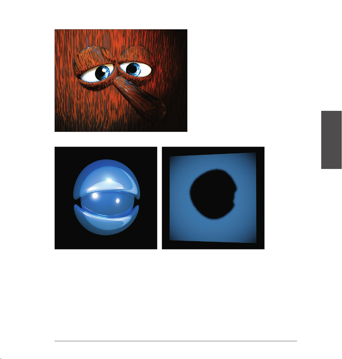
Banzi: ermöglicht die Darstellung verschiedener Holzarten.
Banji: erzeugt korrekte Lichtbrechungen für aufwendiges Glas und ermöglicht die scheinbare Rückprojektion
(Schattenwurf) auf z. B. leicht transparente Materialien wie Reis- oder Butterbrotpapier.
DEUTSCH
38Standalone Quickstart
 Loading...