

M-03-07
REV. E
JUNE 2014
MAINTENANCE MANUAL
72-25 & 72-30
© 2014 MAXON LIFT CORP.


11921 Slauson Ave.
Santa Fe Springs, CA. 90670
LIFT CORP.
CUSTOMER SERVICE:
TELEPHONE (562) 464-0099 TOLL FREE (800) 227-4116
FAX: (888) 771-7713
NOTE: For latest version of all Manuals (and replacements), download the
Manuals from Maxon’s website at www.maxonlift.com.
WARRANTY/ RMA POLICY & PROCEDURE
LIFTGATE WARRANTY
Type of Warranty: Full Parts and Labor
Term of Warranty: Standard Liftgates - 2 years from ship date or 6,000 cycles
Premium Liftgates - 2 years from ship date or 10,000 cycles
This warranty shall not apply unless the product is installed, operated and maintained in accordance with MAXON Lift’s specifi cations as set forth in
MAXON Lift’s Installation, Operation and Maintenance manuals. This warranty does not cover normal wear, maintenance or adjustments, damage or
malfunction caused by improper handling, installation, abuse, misuse, negligence, or carelessness of operation. In addition, this warranty does not
cover equipment that has had unauthorized modifi cations or alterations made to the product.
MAXON agrees to replace any components which are found to be defective during the fi rst 2 years of service, and will reimburse for labor based on
MAXON’s Liftgate Warranty Flat Rate Schedule. (Copy of the Flat Rate is available at www.maxonlift.com.)
All warranty repairs must be performed by an authorized MAXON warranty facility. For any repairs that may exceed $500, including parts and labor,
MAXON’s Technical Service Department must be notifi ed and an “Authorization Number” obtained.
All claims for warranty must be received within 30 Days of the repair date, and include the following information:
1. Liftgate Model Number and Serial Number
2. The End User must be referenced on the claim
3. Detailed Description of Problem
4. Corrective Action Taken, and Date of Repair
5. Parts used for Repair, Including MAXON Part Number(s)
6. MAXON R.M.A. # and/or Authorization # if applicable (see below)
7. Person contacted at MAXON if applicable
8. Claim must show detailed information i.e. Labor rate and hours of work performed
Warranty claims can also be placed online at www.maxonlift.com. Online claims will be given priority processing.
All claims for warranty will be denied if paperwork has not been received or claim submitted via Maxon website for processing by MAXON’s Warranty
Department within 30 days of repair date.
All components may be subject to return for inspection, prior to the claim being processed. MAXON products may not be returned without prior written
approval from MAXON’s Technical Service Department. Returns must be accompanied by a copy of the original invoice or reference with original
invoice number and are subject to a credit deduction to cover handling charges and any necessary reconditioning costs. Unauthorized returns will be
refused and will become the responsibility of the returnee.
Any goods being returned to MAXON Lift must be pre-approved for return, and have the R.M.A. number written on the outside of the package in plain
view, and returned freight prepaid. All returns are subject to a 15% handling charge if not accompanied by a detailed packing list. Returned parts are
subject to no credit and returned back to the customer.
Defective Parts requested for return must be returned within 30 days of the claim date for consideration to:
10321 Greenleaf Avenue, Santa Fe Springs, CA 90670
MAXON’s warranty policy does not include the reimbursement for travel time, towing, vehicle rental, service calls, oil, batteries or loss of income due to
downtime. Fabrication or use of non Maxon parts, which are available from MAXON, are also not covered.
MAXON’s Flat Rate Labor Schedule takes into consideration the time required for diagnosis of a problem.
All Liftgates returned are subject to inspection and a 15% restocking fee. Any returned Liftgates or components that have been installed or not returned
in new condition will be subject to an additional reworking charge which will be based upon the labor and material cost required to return the Liftgate or
component to new condition.
PURCHASE PART WARRANTY
Term of Warranty: 1 Year from Date of Purchase.
Type of Warranty: Part replacement only
MAXON will guarantee all returned genuine MAXON replacement parts upon receipt and inspection of parts and original invoice.
All warranty replacements parts will be sent out via ground freight. If a Rush Shipment is requested all freight charges will be billed to the requesting
party.
MAXON Lift Corp.
Attn: RMA#__

TABLE OF CONTENTS
SUMMARY OF CHANGES: M-03-07, REVISION F ............................................................. 6
WARNING ....................................................................................................................... ...... 7
SAFETY INSTRUCTIONS ....................................................................................................8
LIFTGATE TERMINOLOGY 72-25 & 72-30 .......................................................................... 9
PERIODIC MAINTENANCE ................................................................................................ 10
PERIODIC MAINTENANCE CHECKS ................................................................................ 10
PERIODIC MAINTENANCE CHECKLIST ............................................................................11
CHECKING HYDRAULIC FLUID ........................................................................................12
CHANGING HYDRAULIC FLUID ........................................................................................ 14
PLA TFORM ADJUSTMENT ................................................................................................16
REPLACING PLATFORM TORSION SPRING ................................................................... 18
ADJUST SAFETY HOOK (IF REQUIRED) ........................................................................20
PARTS BREAKDOWNS .....................................................................................................21
72-25 & 72-30 MAIN ASSEMBLY ........................................................................................ 21
EXTENSION PLATE ASSEMBLY ........................................................................................ 22
LIFT FRAME & PARALLEL ARMS ......................................................................................23
PLATFORM & FLIPOVER ASSEMBLY (RAMP) .................................................................24
PLATFORM & FLIPOVER ASSEMBLY (WEDGE) .............................................................. 25
PLATFORM & FLIPOVER ASSEMBLY (SPECIAL PROFILE) ............................................ 26
PUMP COVER & MOUNTING PLATE ASSEMBLY (GRAVITY DOWN) ............................. 27
PUMP COVER & MOUNTING PLATE ASSEMBLY (POWER DOWN) ...............................28
GRAVITY DOWN HYDRAULIC COMPONENTS ................................................................29
12 VDC POWER UNIT (GRAVITY DOWN) ......................................................................... 30

24 VDC POWER UNIT (GRAVITY DOWN) ......................................................................... 32
POWER DOWN HYDRAULIC COMPONENTS .................................................................. 35
12 VDC POWER UNIT (POWER DOWN) ........................................................................... 36
DECALS ..............................................................................................................................38
CONTROL SWITCH AND POWER CABLE ........................................................................40
HYDRAULIC SYSTEM DIAGRAMS ................................................................................... 41
HYDRAULIC SCHEMATIC (GRAVITY DOWN) ................................................................... 41
HYDRAULIC SCHEMATIC (POWER DOWN) ....................................................................42
ELECTRICAL SYSTEM DIAGRAMS .................................................................................43
ELECTRICAL SCHEMATIC (GRAVITY DOWN) ................................................................. 43
ELECTRICAL SCHEMATIC (POWER DOWN) ...................................................................44
TROUBLESHOOTING ........................................................................................................ 45
PLATFORM WILL NOT RAISE ............................................................................................45
PLATFORM RAISES BUT LEAKS DOWN .......................................................................... 46
PLATFORM RAISES PARTIALLY AND STOPS .................................................................. 47
LIFTGATE WILL NOT LIFT RATED CAPACITY .................................................................. 48
PLATFORM RAISES SLOWLY ...........................................................................................49
PLATFORM WILL NOT LOWER, LOWERS TOO SLOWLY OR TOO QUICKLY ................ 50
SUMMARY OF CHANGES: M-03-07, REVISION F
PAGE DESCRIPTION OF CHANGE
COVER Updated REV and date of release and copyright date.
6 Added SUMMARY OF CHANGES
7 Update warning and added decal P/N 282687-01
11921 Slauson Ave. Santa Fe Springs, CA. 90670 (800) 227-4116 FAX (888) 771-7713
8 Added safety instructions
20 Updated Safety Hook instruction
29, 35, 51, 53
30, 36 Clarifi ed torque specs for electrical connections on started solenoid
38-39
Updated fl ow regulator (control) valve P/N 906923-01, HP hose P/N 288241-01 and
description
Replaced WARNING decal P/N 264081 with decal sheet P/N 282522-01.
Inserted new page for Decal Sheet 282522-01 & Warning Decal 282847-02, added
decal 282687-01
6
Comply with the following WARNINGS and SAFETY INSTRUCTIONS while maintaining
Liftgates. See Operation Manual for operating safety requirements.
WARNING
!
WARNING
WARNING
• Do not stand, or allow obstructions, under the platform when lowering the Liftgate. Be sure your
feet are clear of the Liftgate.
• Keep fi ngers, hands, arms, legs, and feet clear of moving Liftgate parts (and platform
edges) when operating the Liftgate.
• Correctly stow platform when not in use. Extended platforms could create a hazard for
people and vehicles passing by.
• Disconnect Liftgate power cable from battery before repairing or servicing Liftgate.
• If it is necessary to stand on the platform while maintaining the Liftgate, keep your feet and any
objects clear of the inboard edge of the platform. Your feet or objects on the platform can become
trapped between the platform and the Liftgate extension plate.
• Recommended practices for welding on steel parts are contained in the current AWS (American
Welding Society) D1.1 Structural Welding Code - Steel. Damage to Liftgate and/or vehicle, and
personal injury could result from welds that are done incorrectly.
• Recommended practices for welding on aluminum parts are contained in the current AWS
(American Welding Society) D1.2 Structural Welding Code - Aluminum. Damage to Liftgate
and/or vehicle, and personal injury could result from welds that are done incorrectly.
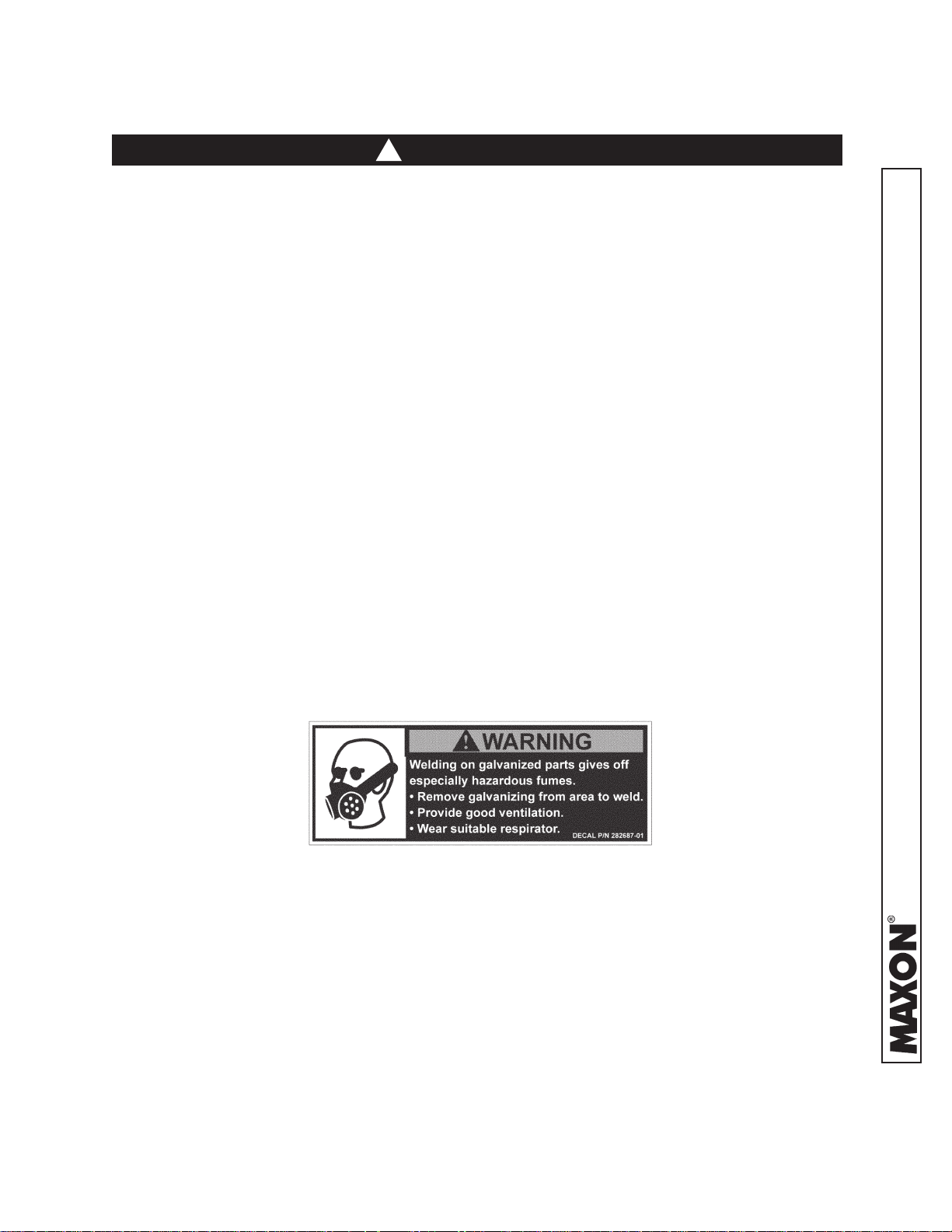
• Welding on galvanized parts gives off especially hazardous fumes. Comply with WARNING decal
on the galvanized part (
adequate ventilation, and wear suitable respirator.
FIG. 7-1). To minimize hazard remove galvanizing from weld area, provide
FIG. 7-1
11921 Slauson Ave. Santa Fe Springs, CA. 90670 (800) 227-4116 FAX (888) 771-7713
7

SAFETY INSTRUCTIONS
SAFETY INSTRUCTIONS
• Read and understand the instructions in this Maintenance Manual before performing mainte-
nance on the Liftgate.
• Before operating the Liftgate, read and understand the operating instructions in Operation
Manual.
• Comply with all WARNING and instruction decals attached to the Liftgate.
• Keep decals clean and legible. If decals are illegible or missing, replace them. Free replacement
11921 Slauson Ave. Santa Fe Springs, CA. 90670 (800) 227-4116 FAX (888) 771-7713
decals are available from Maxon Customer Service.
• Consider the safety and location of bystanders and location of nearby objects when operating the
Liftgate. Stand to one side of the platform while operating the Liftgate.
• Do not allow untrained persons to operate the Liftgate.
• Wear appropriate safety equipment such as protective eyeglasses, faceshield and clothing while
performing maintenance on the Liftgate and handling the battery. Debris from drilling and contact
with battery acid may injure unprotected eyes and skin.
• Be careful working by an automotive type battery. Make sure the work area is well ventilated and
there are no fl ames or sparks near the battery. Never lay objects on the battery that can short the
terminals together. If battery acid gets in your eyes, immediately seek fi rst aid. If acid gets on your
skin, immediately wash it off with soap and water.
• If an emergency situation arises (vehicle or Liftgate) while operating the Liftgate, release the control switch to stop the Liftgate.
• A correctly installed Liftgate operates smoothly and reasonably quiet. The only noticeable noise
during operation comes from the power unit while the platform is raised. Listen for scraping, grating and binding noises and correct the problem before continuing to operate Liftgate.
• Use only Maxon Authorized Parts for replacement parts. Provide Liftgate model and serial number information with your parts order. Order replacement parts from:
MAXON LIFT CORP. Customer Service
11921 Slauson Ave., Santa Fe Springs, CA 90670
Online: www.maxonlift.com
Express Parts Ordering: Phone (800) 227-4116 ext. 4345
Email: Ask your Customer Service representative
8
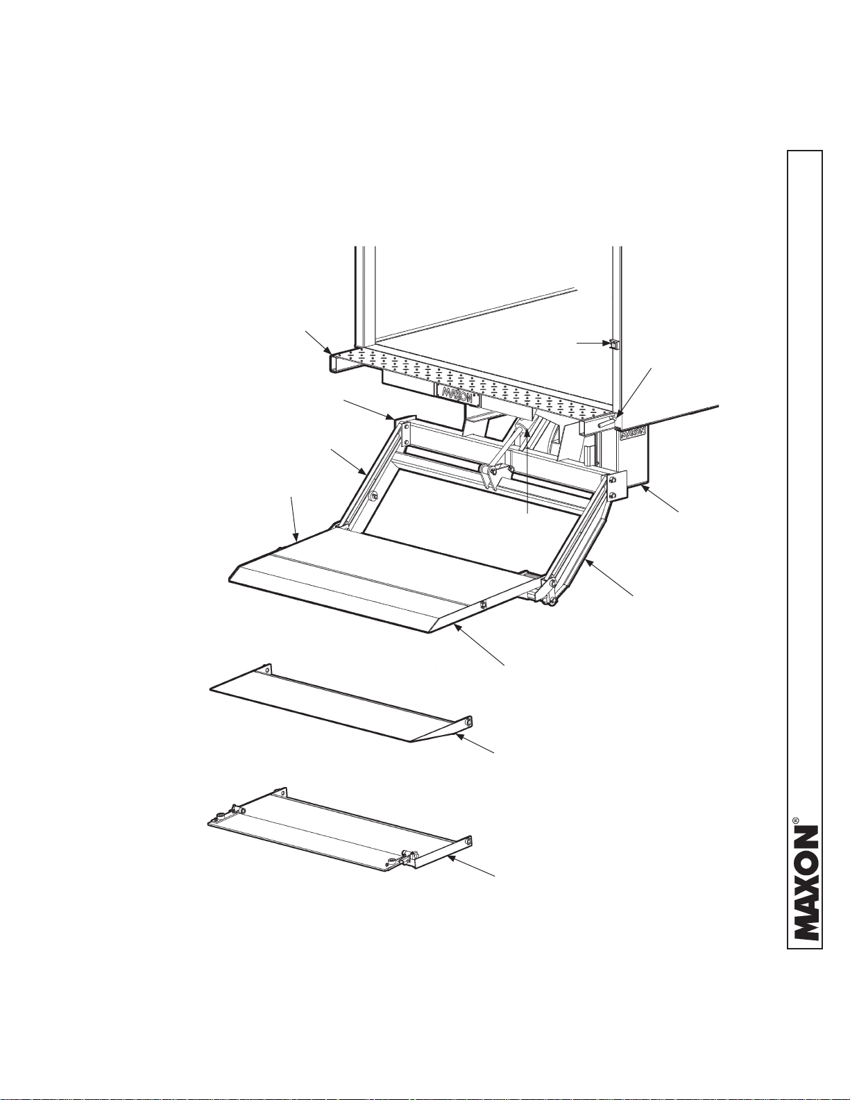
LIFTGATE TERMINOLOGY
72-25 & 72-30
EXTENSION
PLATE
CONTROL
SWITCH
MAIN FRAME
PARALLEL
ARM
PLATFORM
CONTROL
HANDLE
LIFT
CYLINDER
LIFT FRAME
RAMP FLIPOVER
WEDGE FLIPOVER
SPECIAL PROFILE
FLIPOVER
PUMP BOX
11921 Slauson Ave. Santa Fe Springs, CA. 90670 (800) 227-4116 FAX (888) 771-7713
9
PERIODIC MAINTENANCE
PERIODIC MAINTENANCE CHECKS
!
WARNING
Never operate the Liftgate with parts loose or missing.
NOTE: Make sure vehicle is parked on level ground while perform-
ing the maintenance checks.
Quarterly or 1250 Cycles (whichever occurs fi rst)
11921 Slauson Ave. Santa Fe Springs, CA. 90670 (800) 227-4116 FAX (888) 771-7713
Check the hydraulic fl uid level in the pump reservoir. Refer to the CHECKING HYDRAULIC
FLUID procedure in the PERIODIC MAINTENANCE section.
If hydraulic fl uid appears contaminated, refer to the CHANGING HYDRAULIC FLUID
procedure in the PERIODIC MAINTENANCE section.
Keep track of the grade of hydraulic fl uid in the pump reservoir and never mix two different
grades of fl uid.
Check all hoses and fi ttings for chafi ng and fl uid leaks. Tighten loose fi ttings or replace
parts as required.
Check electrical wiring for chafi ng and make sure wiring connections are tight and free of
corrosion. Use dielectric grease to protect electrical connections.
Check that all WARNING and instruction decals are in place. Also, make sure decals are
legible and decals are clean and undamaged.
Check that all bolts, nuts, and roll pins are in place. Make sure roll pins protrude evenly
from both sides of hinge pin collar. Replace fasteners and roll pins if necessary.
Check for rust and oily surfaces on Liftgate. If there is rust or oil on Liftgate or if the Liftgate
is dirty, clean it off. Touch up the paint where bare metal is showing.
Semi-annually or 2500 Cycles (whichever occurs fi rst)
Visually check the platform hinge pins for excessive wear and broken welds. See PARTS
BREAKDOWN section for replacement parts. Also, do the Quarterly or 1250 Cycles main-
tenance checks.
10
PERIODIC MAINTENANCE CHECKLIST
NOTE: Make sure vehicle is parked on level ground while performing the maintenance
checks.
Quarterly or 1250 Cycles (whichever occurs fi rst)
Check the level and condition of the hydraulic fl uid.
Visually check all hoses for chafi ng and fl uid leaks. Tighten loose fi ttings or replace
parts as required.
Check electrical wiring for chafi ng and make sure wiring connections are tight and free
of corrosion. Use dielectric grease to protect electrical connections.
Check that all WARNING and instruction decals are in place. Also, make sure decals
are legible, clean and undamaged.
Check that all bolts, nuts, and roll pins are in place. Make sure roll pins protrude evenly
from both sides of hinge pin collar. Replace fasteners and roll pins if necessary.
CAUTION
Damaged cylinder seals and contaminated hydraulic fl uid can result from
painting the polished portion of the cylinder rod. To prevent damage, protect
the exposed polished portion of the cylinder rod while painting.
Check for rust and oily surfaces on Liftgate. If there is rust or oil on Liftgate or if the Liftgate is dirty, clean it off. Touch up the paint where bare metal is showing.
Semi-annually or 2500 Cycles (whichever occurs fi rst)
Visually check the platform hinge pins for excessive wear and broken welds.
Do the Quarterly or 1250 Cycles Checks on this checklist.
11921 Slauson Ave. Santa Fe Springs, CA. 90670 (800) 227-4116 FAX (888) 771-7713
11
PERIODIC MAINTENANCE
CHECKING HYDRAULIC FLUID
CAUTION
Keep dirt, water and other contaminants from entering the hydraulic system.
Before opening the hydraulic fl uid reservoir fi ller cap, drain plug and hydrau-
lic lines, clean up contaminants that can get in the openings. Also, protect the
openings from accidental contamination.
11921 Slauson Ave. Santa Fe Springs, CA. 90670 (800) 227-4116 FAX (888) 771-7713
NOTE: Use correct grade of hydraulic fl uid for your location.
+50 to +120 Degrees F - Grade ISO 32
Below + 70 Degrees F - Grade ISO 15 or MIL-H-5606
See TABLES 13-2 and 13-3 for recommended brands.
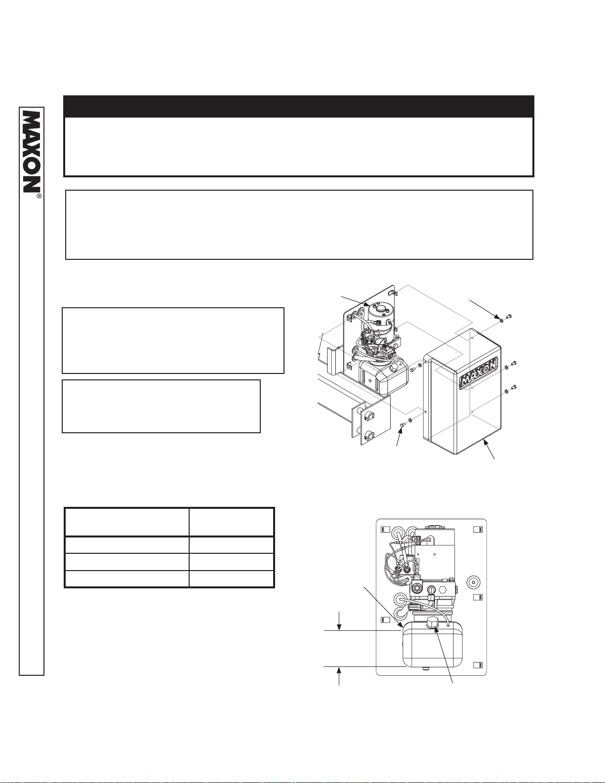
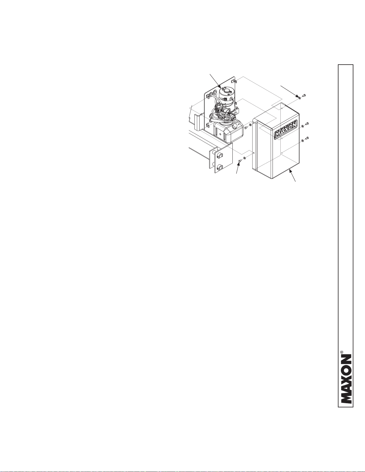
1. Unbolt & remove pump cover (FIG. 12-1).
NOTE: If the hydraulic fl uid in the
reservoir is contaminated, do
the CHANGING HYDRAULIC
FLUID procedure in this section.
NOTE: If you have a power down
power unit, skip instructions
2 & 3.
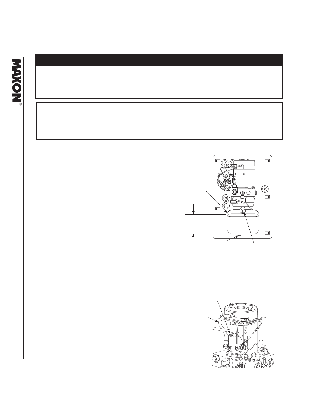
2. For gravity down power unit, check the
hydraulic fl uid level “H” in reservoir (FIG.
12-2 and TABLE 12-1). If needed, add
fl uid to the reservoir as follows.
PLATFORM POSITION
STOWED 1-7/8” to 2-3/8”
FLUID LEVEL
“H”
POWER UNIT
(REF)
CAP SCREWS
(5 PLACES)
FLAT WASHERS
(5 PLACES)
PUMP COVER
UNBOLTING / BOLTING PUMP COVER
FIG. 12-1
VEHICLE BED HEIGHT 1-7/8” to 2-3/8”
ON THE GROUND 3-1/2” to 4”
GRAVITY DOWN FLUID LEVEL
TABLE 12-1
3. Pull out (no threads) fi ller cap (FIG. 12-2).
Fill the reservoir with hydraulic fl uid to level
“H” shown in FIG. 12-2 and TABLE 12-1.
Reinstall fi ller cap (FIG. 12-2)
RESERVOIR
“H”
FILLER CAP
GRAVITY DOWN POWER UNIT
FIG. 12-2
12
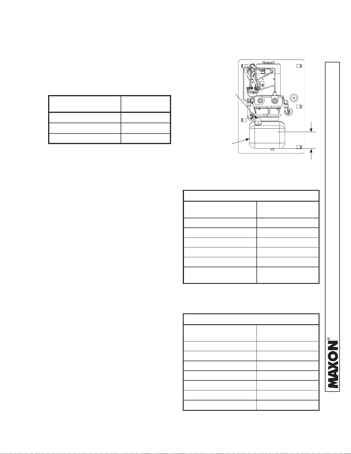
4. For power down power unit, check the hydraulic
fl uid level “H” in reservoir (FIG. 13-1 and TABLE
13-1). If needed, add fl uid to the reservoir as fol-
lows.
PLATFORM POSITION
STOWED 2-5/8” to 3-1/8”
VEHICLE BED HEIGHT 2-5/8” to 3-1/8”
FLUID LEVEL
“H”
FILLER
CAP
ON THE GROUND 2-3/8” to 2-7/8”
POWER DOWN FLUID LEVEL
TABLE 13-1
5. Pull out (no threads) fi ller cap (FIG.
13-1). Fill the reservoir with hydraulic
fl uid to level “H” shown in FIG. 13-1
and TABLE 13-1. Reinstall fi ller cap
(FIG. 13-1).
6. Bolt on the pump cover (FIG. 12-1).
Torque the bolts (cap screws) to
10 - 14 lbs.- in.
RESERVOIR
POWER DOWN POWER UNIT
FIG. 13-1
ISO 32 HYDRAULIC OIL
RECOMMENDED
BRANDS
AMSOIL AWH-05
CHEVRON HIPERSYN 32
KENDALL GOLDEN MV
SHELL TELLUS S2 V32
EXXON UNIVIS N-32
MOBIL
PART NUMBER
DTE-13M, DTE-24,
HYDRAULIC OIL-13
TABLE 13-2
“H”
ISO 15 OR MIL-H-5606 HYDRAULIC OIL
RECOMMENDED
BRANDS
AMSOIL AWF-05
CHEVRON FLUID A, AW-MV -15
KENDALL GLACIAL BLU
SHELL TELLUS S2 V15
EXXON UNIVIS HVI-13
MOBIL DTE-11M
ROSEMEAD THS FLUID 17111
PART NUMBER
TABLE 13-3
13
11921 Slauson Ave. Santa Fe Springs, CA. 90670 (800) 227-4116 FAX (888) 771-7713
PERIODIC MAINTENANCE
CHANGING HYDRAULIC FLUID
CAUTION
Keep dirt, water and other contaminants from entering the hydraulic system.
Before opening the hydraulic fl uid reservoir fi ller cap, drain plug and hydrau-
lic lines, clean up contaminants that can get in the openings. Also, protect the
openings from accidental contamination.
11921 Slauson Ave. Santa Fe Springs, CA. 90670 (800) 227-4116 FAX (888) 771-7713
NOTE: Use correct grade of hydraulic fl uid for your location.
+50 to +120 Degrees F - Grade ISO 32
Below + 70 Degrees F - Grade ISO 15 or MIL-H-5606
See TABLES 13-2 and 13-3 for recommended brands.
GRAVITY DOWN LIFTGATES
1. Remove the pump cover (FIG. 15-1). Place emp-
ty 5 gallon bucket under drain plug (FIG. 14-1).
2. Lower platform to ground. Pull out (no
threads) drain plug (FIG. 14-1). Drain hydraulic
fl uid from system. Reinstall drain plug.
3. Pull out (no threads) fi ller cap (FIG. 14-1) and
refi ll reservoir with hydraulic fl uid to level shown in
FIG. 14-1. Reinstall fi ller cap (FIG. 14-1).
4. Bolt on the pump cover as shown in FIG. 15-1
Torque the bolts (cap screws) to 10 - 14 lbs.- in.
POWER DOWN LIFTGATES
1. Remove the pump cover (FIG. 15-1). Place emp-
ty 5 gallon bucket under drain plug (FIG. 14-1).
RESERVOIR
3-1/2” - 4”
DRAIN
PLUG
FILLER CAP
LIFTGATE SHOWN WITH GRAVITY
DOWN PUMP & MOTOR
FIG. 14-1
2. Open and raise platform to vehicle bed height. Pull
out (no threads) drain plug (FIG. 14-1). Drain hydraulic fl uid.
3. Disconnect the motor power cable (FIG. 14-
2) from starter solenoid. Lower the platform
while draining the remaining hydraulic fl uid from
system. Reinstall drain plug. Reconnect the
motor power cable to starter solenoid.
4. Pull out (no threads) fi ller cap (FIG. 14-1) and
refi ll reservoir with hydraulic fl uid to level shown
in FIG. 14-1. Reinstall fi ller cap (FIG. 14-1).
14
STARTER
SOLENOID
MOTOR
POWER
CABLE
POWER DOWN PUMP
FIG. 14-2
5. Bolt on the pump cover as shown in
FIG. 15-1. Torque the bolts (cap
screws) to 10 - 14 lbs.- in.
POWER UNIT
(REF)
CAP SCREWS
(5 PLACES)
FLAT WASHERS
(5 PLACES)
PUMP COVER
UNBOLTING / BOLTING PUMP COVER
FIG. 15-1
15
11921 Slauson Ave. Santa Fe Springs, CA. 90670 (800) 227-4116 FAX (888) 771-7713
PERIODIC MAINTENANCE
PLA TFORM ADJUSTMENT
NOTE: Before doing the following procedure,
make sure vehicle is parked on level
ground.
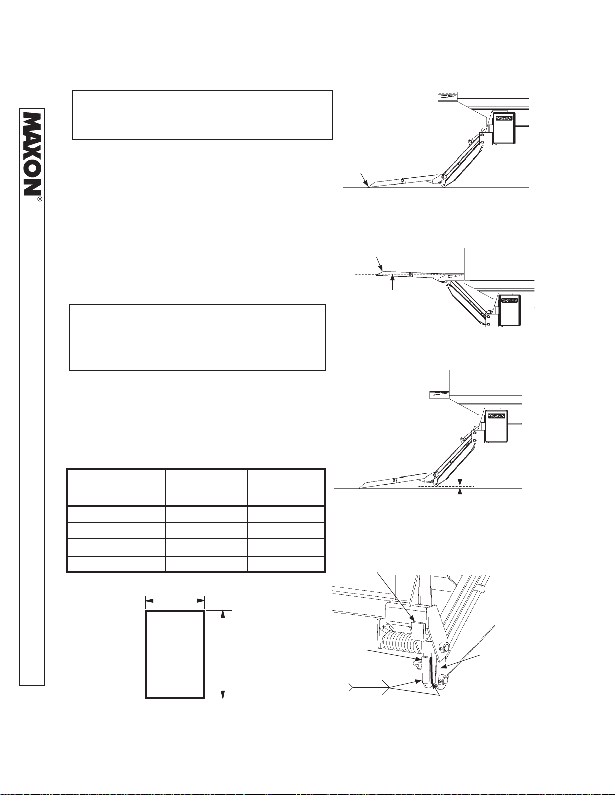
1. Make sure platform is at ground level. Unfold the
platform and fl ipover. As the platform fi rst touches
the ground, shackles and tip of fl ipover must touch
the ground at the same time (FIG. 16-1). If the
11921 Slauson Ave. Santa Fe Springs, CA. 90670 (800) 227-4116 FAX (888) 771-7713
shackles and the tip of fl ipover touch the ground
at the same time, raise platform to bed height.
Outboard edge on top of fl ipover should be above
bed level (FIG. 16-2). If indications are correct in
both cases (FIGS. 16-1 & 16-2), Liftgate is installed correctly and no adjustment is needed. If
indications are incorrect, continue to instruction 2.
NOTE: If tip of fl ipover touches fi rst (FIG.
16-3), do instruction 2. If the shackle
touches fi rst (FIG. 17-1), skip instruc-
tion 2 and do 3.
2. Make sure platform is still at ground level. If
the shackle is not touching the ground, measure and compare distance “A” (FIG. 16-3)
with TABLE 16-1 to determine the correct
shim. Make shims as needed (FIG. 16-5).
Weld shim as shown in FIG. 16-4.
RAISE TIP OF
FLIPOVER
THIS DISTANCE “A”
7/8” 1/16” 1/16”
1-3/4” 1/8” 1/8”
2-5/8” 3/16” 3/16”
3-1/2” 1/4” 1/4”
REQUIRED SHIM
THICKNESS
WELD SIZE “W”
TIP OF
FLIPOVER
FLIPOVER & SHACKLES
TOUCH GROUND
FIG. 16-1
OUTBOARD
EDGE
LEVEL LINE
FLIPOVER EDGE ABOVE
BED LEVEL
FIG. 16-2
“A”
(TABLE 16-1)
SHACKLES DO NOT TOUCH
GROUND
FIG. 16-3
EXISTING STOP
TABLE 16-1
1-1/2”
2-1/4”
SHIM (1/16”, 1/8”, 3/16”, or 1/4”)
MADE FROM STEEL FLAT
FIG. 16-5
NEW SHIM
“W”
TABLE 16-1
SHACKLE
WELDING SHIMS (CURBSIDE SHOWN)
FIG. 16-4
16
 Loading...