

Page 1

11535 W. 83rd Terrace, Lenexa, KS 66214
Toll-Free: 800-456-2071 (US Only), 913-859-9515
Website: www.maxonamerica.com
Printed in Korea
Page 2
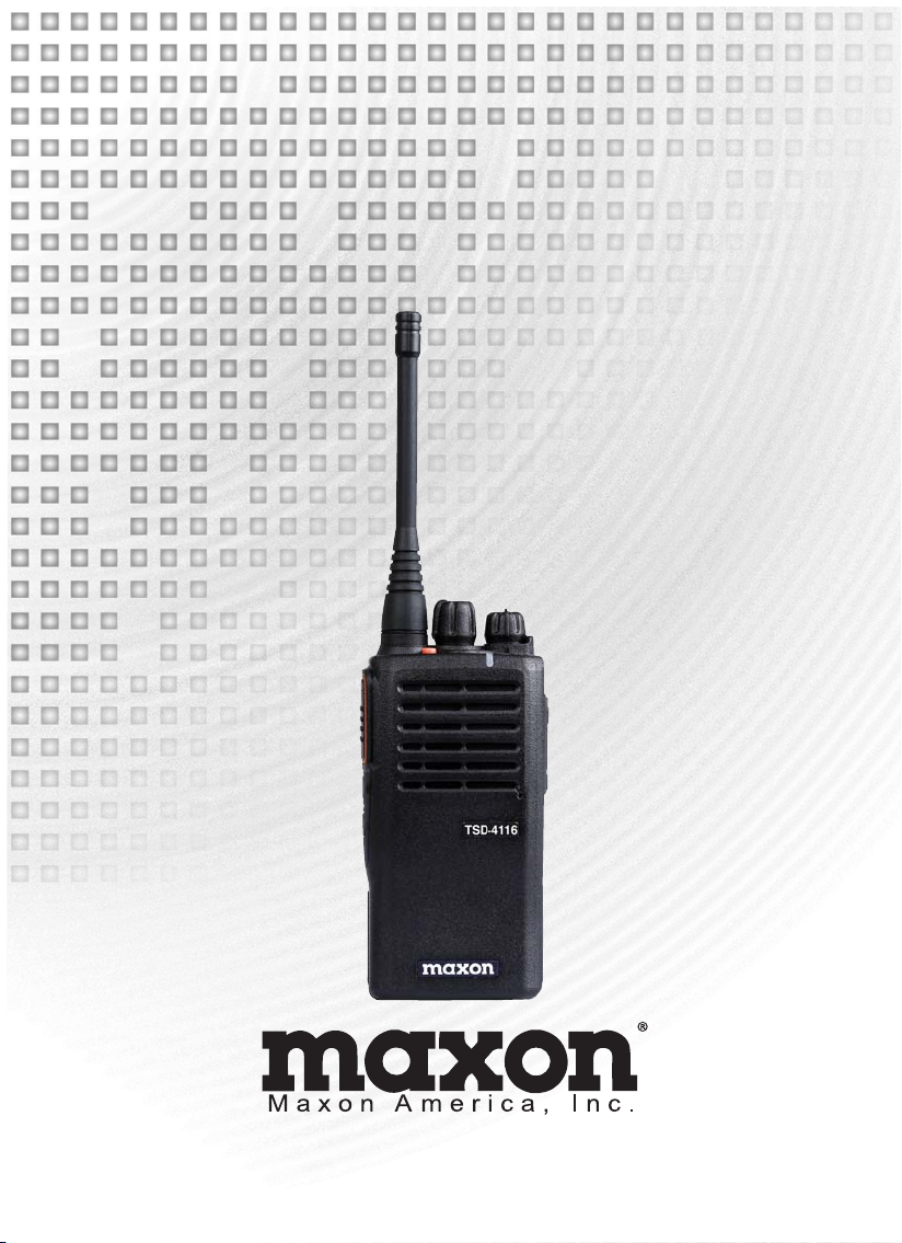
User’s Manual
TSD-4000 Series
(DMR/Analog)
TSD-4116 (VHF)
TSD-4416 (UHF)
11535 W. 83rd Terrace, Lenexa, KS 66214
Toll-Free: 800-456-2071 (US Only), 913-859-9515
Website: www.maxonamerica.com
Page 3
Table of Contents
1. Specifications
2. Features
3. In-Box Contents
4. Controls & Appearance of TSD-4000 Series radio
5. Battery and Belt Clip Installation and Removal
6. Charging the Battery
7. Function & Operation
8. Precautions for Safe Operation
9. For Safe Operation
10. Warranty Statement
3
3
4
5
6
6
8
9
10
11
Thank you for purchasing the TSD-4000 Series radio
1. Before operating the radio, please read the user manual carefully.
2. Functions and specifications are subject to be changed without notice for improvement of the radio
performance.
2
Page 4
1. Specifications
TSD-4000 Series Radio Specifications
www.tecnetusa.comwww.tecnetusa.com
www.maxonamerica.com
Frequency Range
Digital
Programmable Channels
Dimensions (H/W/D)
Weight w/battery
Power Source
Sensitivity
RF Power Output
Audio Power Output
Frequency Stability
Channel Spacing
Digital Vocoder
Dust and Water Protection
U.S. Military Standard
Operating Temperature
Storage Temperature
2. Features
TSD-4116: 136 ~ 174 MHz
TSD-4416: 400 ~ 470 MHz
DMR Tier II TDMA
512 Channels: 16 Channels with 32 Zones per channel
4.6 x 2.16 x 1.33
234g
DC +7.4V Li-ion 2,600mAH Battery
0.25
12 dB SINAD (Analog)
0.22
/BER 5% (Digital)
5/1 Watt (UHF & VHF)
1 Watt
1.5 PPM (-30° to +60° C)
25/20/12.5 kHz (Analog) 12.5 kHz (Digital) 2 Time Slots of 6.25 Each
AMBE3000 Vocoder Chip with AMBE+2 Voice Compression Algorithm
IP-54
MIL-STD 810F/G
-30°C to +60°C
-40°C to +85°C
(118x55x34 mm)
1. AES Encryption (128, 192, 256)
2. Channel Tri-Mode (Digital, Analog, Mixed): compatible with the prevalent analog system,
ensuring a smooth analog-to-digital transition. Mixed mode allows your digital radio to receive
current analog radios yet transmit digitally to other DMR radios.
3. Long Battery Life: 14hours (Analog) / 23 hours (Digital) on 90/5/5 duty cycle
4. CTCSS / DCS
3
Page 5
3. In-Box Contents
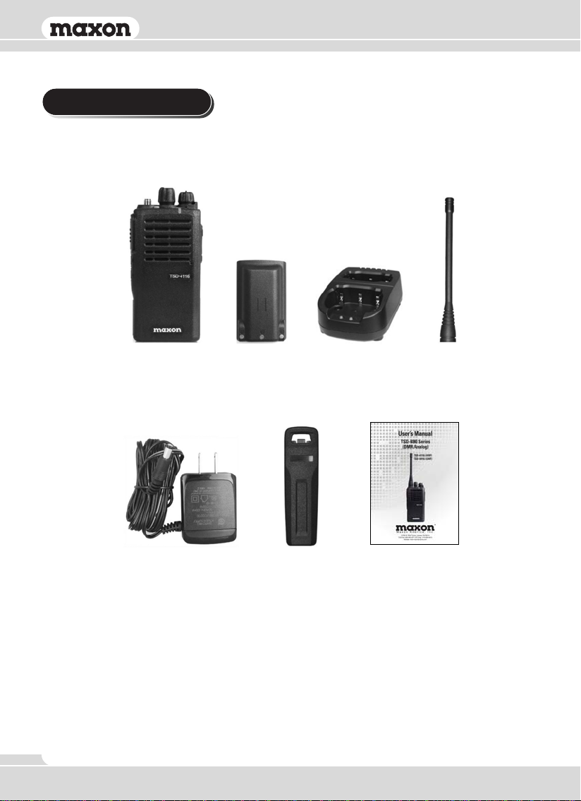
Radio
DC Adaptor
Battery
Contents subject to change at buyer’s request.
Dual Slot Charger Antenna
Belt clip
User Manual
4
Page 6
www.maxonamerica.com
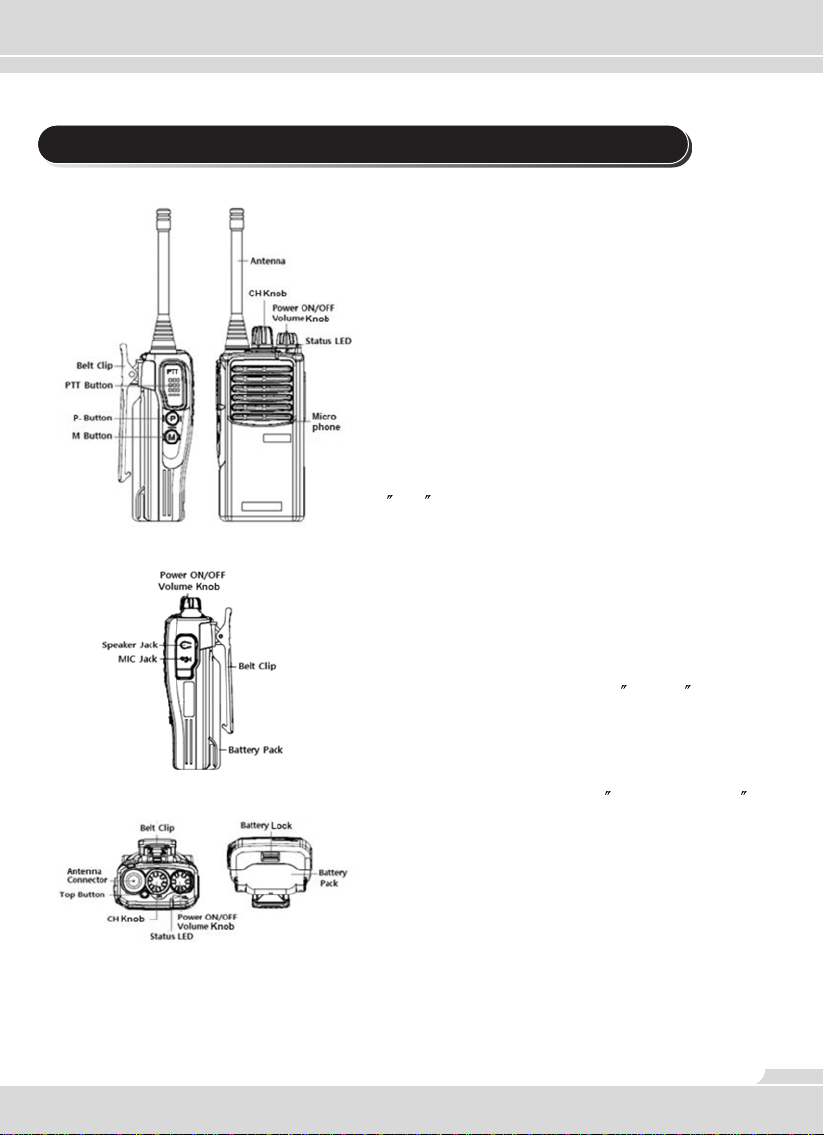
4. Controls and Appearance of TSD-4000 Series Radio
Power ON/OFF Volume Knob
Turns the radio on and off & adjusts the audio
volume level.
Channel Knob
Change channels by turning the control knob
clock-wise or counter-clockwise. 16 Channels can be
inputted into each zone. A voice response will notify
the user when the channel has been changed.
If the channel is not assigned, the radio will beep.
PTT Button
Press the PTT button to transmit voice. Release the
PTT button to receive voice. It is recommended to talk
2
to 4 away from the microphone.
P Button
Default function of this button is to easily toggle
between high transmit power and low transmit power to
save battery life. This button can be reassigned
through radio programming.
M Button
Default function of this button is to Monitor the open
channel. This button can be re-assigned through radio
programming.
TOP Button (Orange)
Default function of this button is Emergency / SOS ,
This button can be assigned a different function
through radio programming.
Speaker/MIC Jack
Accessory connector is used to connect an external
speaker microphone or a headset. If it is not used, the
cover should remain closed to prevent dirt from
entering the radio.
Status LED
Used to determine Rx/Tx status and battery charge
level.
5
Page 7
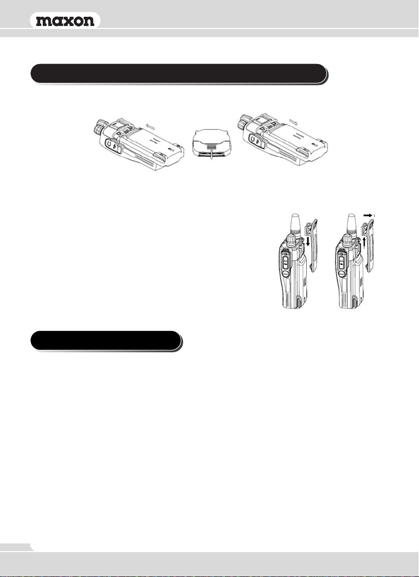
5. Battery and Belt Clip Installation and Removal
How to install the battery How to remove the battery
Attached when the battery pack is pushed up.
Pull the battery lock down and remove the battery
by sliding it toward the arrow
Belt clip installation: Align belt clip to the radio as in the
1st illustration and then slide belt clip down as illustrated until the
belt clip lock clicks.
Belt clip removal: Pull the belt clip lock away from the back
of the radio as in the 2nd illustration (Direction arrow #1) and, at the
same time, slide the belt clip up and out of the locking bracket
(Direction arrow #2).
6. Charging the Battery
Safety Notes
1. TSD-4000 Series radios use a high-performance, 2600 mAh Li-ion battery (TSA-4260).
2. Please charge the battery before using the radio. Use only the recommended charger for best
results.
Charging Information
Low battery voltage may reduce communication coverage and affect the radio’s performance.
Please charge the battery in case of following:
1. When radios performance has degraded.
2. When the RX/TX LED on the radio blinks red (every 0.5 second), during idle, transmission, or
reception.
Three audible beeps will be heard in this state and functionality will be affected.
6
Page 8
www.maxonamerica.com
How to Charge
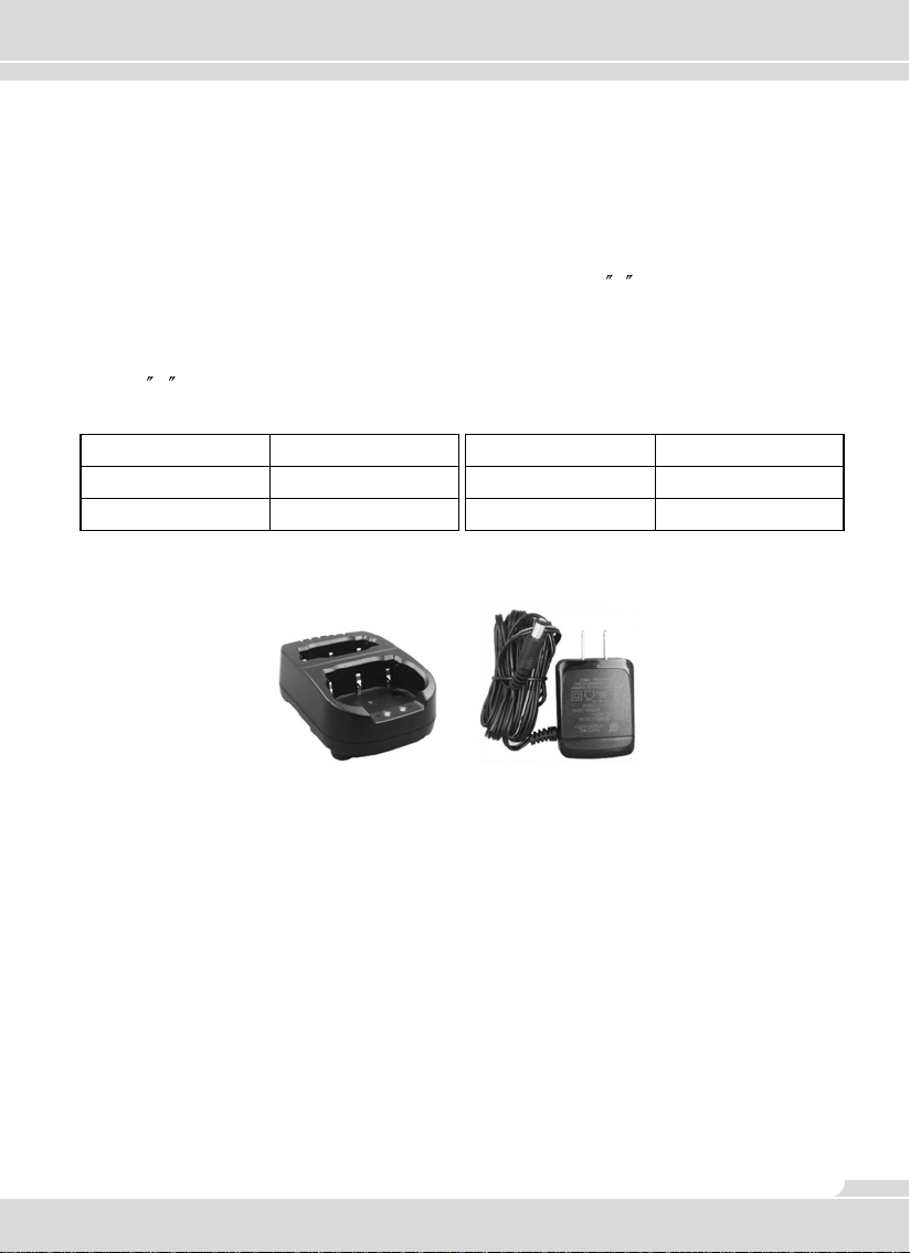
1. Make sure power adaptor for the Dual Slot charger is plugged into the charger and then plug the
power adapter for the TSA-0400 charger into a AC120V power outlet.
2. Turn off the radio before charging.
3. Insert radio into the charger’s larger, front charging port with the charging contacts on the outside
of the radio lined up with the contacts on the charger. LED labeled
when the connection is made.
4. If charging the battery only, line up the outside contacts of the battery with the charging contacts
on the 2nd, smaller charging slot in the rear of the dual charger and then insert the battery. LED
labeled
5. It is recommended to charge another 30 minutes after the LED turns green for a complete charge.
R on the charger will turn on when the connection is made.
F on the charger will turn on
Status
Charging
Complete charging
Charger (TSA-0400)
LED indication
Red LED lights
Green LED lights
TSA-0400 Dual Slot Battery Charger and Power Adaptor
Status
Detecting Error
Keep Charging
LED indication
Red LED blinks
Green LED lights
7
Page 9
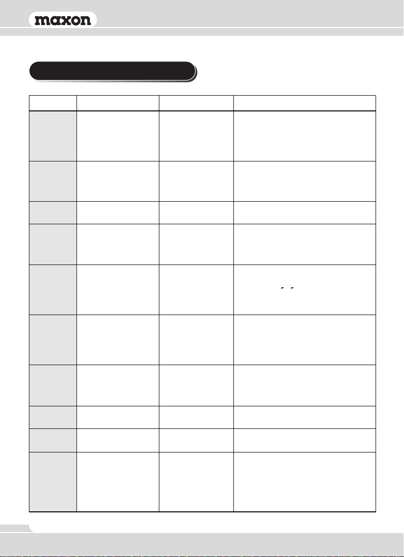
7. Function and Operation
Function Status LEDButton & Setting Descriptions
Power up chime is heard then current
Power
ON/OFF
Transmit
(TX)
Receive
(RX)
Channel
Change
Adjust TX
Output
Power
Monitor
Emergency
Switch Zone
VOX
SCAN
ON/OFF/Volume
Control Knob
PTT Button
Channel knob
(P) Button
*Programmable Button
(M) Button
*Programmable Button
Orange button on top.
*Programmable Button
PC programmable
function
PC programmable
function
PC programmable
function
Orange
High Power: Red
Low Power: Orange
Green
Flashes Orange
during channel
switch
Orange
Green w/ Voice
notification
Voice notification
Voice notification
Voice notification
radio channel selected will be spoken.
If radio is on an unprogrammed
channel, radio will beep. LED will be
orange during power up.
Press and HOLD PTT to talk, release
to listen. Other buttons can be
programmed with the PTT function
through your dealer’s software.
Steady green for decode. If channel is
busy, the LED blinks.
Turn the channel knob to the channel
you want. Voice will state what channel
you are on. If channel is not
programmed, radio will beep.
You can toggle between High Transmit
(TX) power and Low TX power by
pressing the
announcement will indicate High or
Low Power setting.
User can check whether the Receive
Transmission (RX) of current channel
is OK or Not. Press and release the
(M) button to open the squelch on an
analog channel.
In an emergency, press the orange
colored Emergency button for 3
seconds to activate a siren & transmit
an emergency call to your party.
Allows you to change the calling area
to use more channels
Used for transmitting voice without
pressing the PTT Button
Scan button initiates the scan of each
channel in the scan list for activity. If
channel is busy, the radio stops scan
and received audio is heard. Scan
resumes when hang timer expires.
Normal & Priority Scan are available.
P Button. Voice
8
Page 10
www.maxonamerica.com
Stun/Revive
Encryption
(Digital Channel
Only)
Remote
Monitor
Remote
Check
Talkaround /
Repeater
Keypad
Lock/Unlock
PC programmable
function
PC programmable
function
PC programmable
function
PC programmable
function
PC programmable
function
PC programmable
function
Voice notification
Voice notification
No indication on
target radio
Voice notification
Voice notification
Voice notification
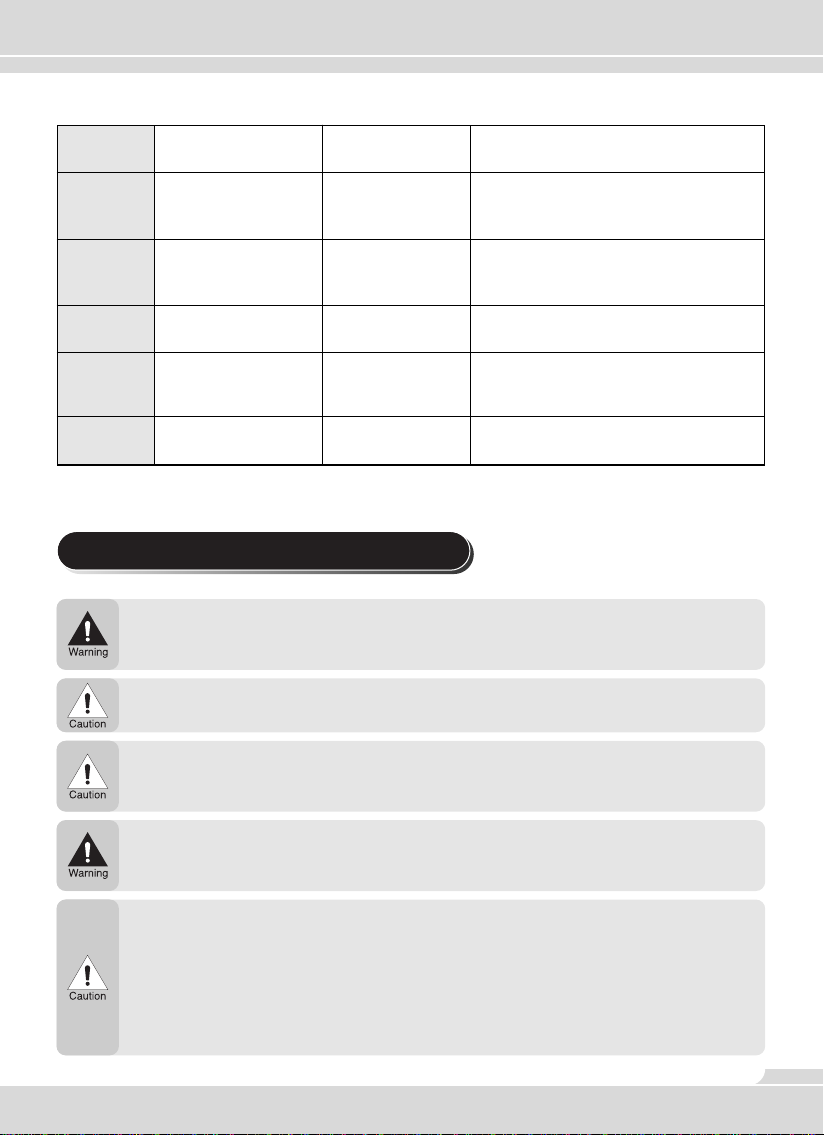
8. Precautions for Safe Operation
Don’t transmit with antenna detached from the radio and do not damage or change antenna type.
Strong electronic waves are emitted from the radio, and damage or changes to the antenna may affect
the performance of the radio and may cause the radio to be defective and not covered under warranty.
Don’t use other manufacturers accessories. Unknown or unauthorized accessories may cause the
radio to be defective and not covered under warranty.
Used to disable and then revive radio
remotely via another radio
Uses AES Encryption (128, 192, 256) to
scramble & unscramble voice
transmissions for privacy.
Turns on radio’s microphone to monitor
any audible activity surrounding the
target radio.
Checks whether target radio in your
contact list is receiving.
Switches the current channel from
repeater mode to talkaround mode and
visa-versa.
Locks and unlocks the keypad. This
feature prevents accidental key presses
Avoid excessive shock to the radio.
Do not place the radio where the direct sunlight or high temperature occurs.
Do not damage battery pack with a sharp object or excessive shock.
Turn off the radio before boarding an airplane.
Do not use the radio in a hospital without pre-approval.
Radio may cause interference around computers or other electronics devices.
Please keep the radio at least 1 inch away from the human body.
Any damage to the antenna, may cause RF exposure.
When using earphones, please reduce the volume to a low level. Unexpected high volume may have
harmful effects to your ear.
Do not touch the conductive metal of the battery radio with wet hands. It may cause damage on your
hands.
Please be careful when putting the battery in a pocket or a bag to avoid contact with metal.
9
Page 11

9. For Safe Operation
•
FCC RF EXPOSURE COMPLIANCE REQUIREMENTS FOR OCCUPATIONAL USE ONLY
The Federal Communications Commission (FCC), with its action in General Docket 93-62, November 7, 1997, has
adopted a safety standard for human exposure to Radio Frequency (RF) electromagnetic energy emitted by FCC
regulated equipment. Proper operation of this radio will result in user exposure far below the Occupational Safety and
Health Act (OSHA) and Federal Communications Commission limits.
•
DO NOT
time can cause FCC RF exposure compliance requirements to be exceeded.
This radio is NOT approved for use by the general population in an uncontrolled environment. This radio is restricted
•
to occupational use, work related operations only where radio operator must have the knowledge to control the user’s
exposure conditions for satisfying the higher exposure limit allowed for occupational use.
When transmitting, hold the radio in a vertical position with its microphone 1 inches (2.5 cm) away from your mouth.
•
The radio is transmitting when the red LED on the front of the radio is illuminated. You can cause the radio to transmit
•
by pressing the PTT bar on the radio.
These are required operating configurations for meeting FCC RF exposure compliance. Failure to observe these
•
restrictions mean violation.
transmit for more than 50% of total radio use time (50% duty cycle). Transmitting more than 50% of the
FCC Notice
This device complies with part 15 of the FCC rules. Operation is subject to the following two conditions: (1) This
devices may not cause harmful interference and (2) This device must accept any interference received, including
interference that may cause undesired operation.
10
Page 12

www.maxonamerica.com
10. Warranty Statement
Maxon America Inc. offers to the original end user:
One (1) Year Limited Warranty on TSD-4000 Series Radios (separate warranty
period on accessories).
One (1) Year Limited Warranty on Accessories (includes, but not limited to,
batteries, antennas, belt clips, chargers, audio accessories, nylon cases, leather
cases, etc.) .
Maxon warrants each new radio product manufactured or supplied by it to be free from defects in material
and workmanship under normal use and service for the time period stated, provided that the user has
complied with the requirements stated herein. The warranty period begins on the date of purchase from
an Authorized Dealer. This warranty is not assignable or transferable. This warranty is void if the product
serial number is altered, defaced or removed. Maxon is not responsible for any equipment that is attached
to or used in conjunction with our products.
During the warranty period, if the product fails to function under normal use, because of manufacturing
defects or workmanship, it should be returned to the Authorized Dealer from which it was purchased. The
Authorized Dealer will repair the product or return the product for repair to Maxon or its Authorized Repair
Depot. The user is responsible for the removal of the product from a vehicle or any equipment attached to
it, or other site of its use; transportation of the product to the Authorized Dealer; for the return of the
repaired or replacement product to the site of its use and for the reinstallation of the product.
Maxon shall have no obligation to make repairs or replacement of product which results from normal wear
and tear, or is necessitated by catastrophe, fault, or negligence of the user, improper or unauthorized
alterations or repairs to the product, incorrect wiring, use for which it was not designed or by causes
external to the product. Maxon’s sole obligation shall be to replace or repair the product covered by the
warranty. Replacement is done at Maxon’s discretion and may consist of a similar or higher featured
product. Repair may include the replacement of parts with functionally equivalent new or reconditioned
parts. All replaced parts and accessories are warranted for the balance of the original time period. All parts
and accessories that are replaced become the property of Maxon America Inc.
THE EXPRESS WARRANTIES CONTAINED HEREIN ARE IN LIEU OF ALL OTHER WARRANTIES,
EITHER EXPRESSED OR IMPLIED OR STATUTORY, INCLUDING, WITHOUT LIMITATION, ANY
WARRANTY OF MERCHANTABILITY OR FITNESS FOR A PARTICULAR PURPOSE.
FOR ANY PRODUCT THAT DOES NOT COMPLY WITH THE WARRANTY SPECIFIED, THE SOLE
REMEDY WILL BE REPAIR OR REPLACEMENT. IN NO EVENT WILL TECNET BE LIABLE FOR ANY
DAMAGES, INCLUDING ANY SPECIAL, INCIDENTAL, INDIRECT OR CONSEQUENTIAL DAMAGES,
OR THE LOSS OF PROFIT, REVENUE OR DATA ARISING OUT OF THE USE OF OR THE INABILITY
TO USE THE PRODUCT
11
 Loading...