

Maxon TM-2102, TM-2402, TM-8402, TM-8404, TM-8102 User Manual
...
11535 W. 83rd Terrace, Lenexa, KS 66214
Toll-Free: 800-456-2071 (US Only)
Phone: 913-859-9515
Website: www.maxonamerica.com
Email: maxon@maxonamerica.com
Printed in Korea
USER MANUAL
VHF Transceiver
TM-2102 / TM-8102 / TM-8104
UHF Transceiver
TM-2402 / TM-8402 / TM-8404
11535 W. 83rdTerrace, Lenexa, KS 66214
www.maxonamerica.com


Table of Contents
www.maxonamerica.com
1. Safety / Warnings
2. Features
3. Appearance of TM-2000 / TM-8000 Series Mobile Radio
4. Controls & Keys
5. Menu Description
6. Terminal Description
7. Specifications
8. Warranty Statement
2
5
6
7
15
24
26
28
1
1. Safety / Warnings
Notices
Government law restricts the operation of unlicensed radio transmitters within government
controlled territories.
Illegal operation is punishable by fine or imprisonment or both.
Refer service to qualified technicians only.
EXPLOSIVE ATMOSPHERES (GASES, DUST, FUMES, etc.)
Shut OFF the transceiver while refueling or while parked in gasoline service stations.
Do not carry spare fuel containers in the trunk of your vehicle if your transceiver is mounted in the
trunk area
INJURY FROM RADIO FREQUENCY TRANSMISSIONS
Do not operate your transceiver when somebody is either touching the antenna or standing within
two to three feet of it to avoid the possibility of radio frequency burns or related physical injury.
Precautions
Please read carefully the following precautions to prevent fire, personal injury, or transceiver
damage:
Do not attempt to configure your transceiver while driving, it is dangerous.
This transceiver is designed for a 13.8V DC power supply. If installing radio into equipment using
a 24V ignition system, voltage supplied to the radio must be reduced to below 16V DC to avoid
damage to the radio.
Do not put the transceiver in excessively dusty, humid or wet areas, nor unstable surfaces.
Do not modify the transceiver for any reason.
Please keep it away from interferential devices (such as TV, generator, medical devices, etc.)
Do not expose the transceiver to long periods of direct sunlight nor place it close to heating
appliances.
If an abnormal odor or smoke is detected coming from the transceiver, turn OFF the power
immediately. Contact an Authorized Dealer.
Do not transmit with high output power for extended periods; the transceiver may overheat.
Do not operate the transceiver when vehicle engine is stopped for extended periods. The
vehicle engine may not be started due to low battery.
Do not use incompatible accessories from other manufacturers. It could result in damage and or
malfunction to the accessory and or to the radio.
2
Preparation
Electronic equipment in your vehicle may malfunction if they are not properly protected from the
radio frequency energy which is present while transmitting.
Typical examples include electronic fuel injection, anti-skid braking, and cruise control. If your
vehicle contains such equipment, consult the dealer in determining if they will perform normally
while transmitting.
Power Cable Connection
The transceiver operates on 12V negative ground systems only! Check the battery polarity and
voltage of vehicle before installing the transceiver.
www.maxonamerica.com
1. Check for an existing hole, conveniently located in the firewall, where the power cable can be passed through.
If no hole exists, use a circle cutter to drill a hole, then install a rubber grommet.
2. Run the power cable though the firewall and into the engine compartment.
3. Connect the red lead to the (+) battery terminal and the black lead to the negative (-) battery terminal.
Place the fuse as close to the battery as possible.
4. Coil the surplus cable and secure it with a retaining band.
Be sure to leave enough slack in the cables so the transceiver can be removed for servicing while keeping
the power applied.
Installing the Transceiver
For passenger safety, install the transceiver securely using the supplied mounting bracket and
screw set so the transceiver will not break loose in the event of a collision.
1. Mark the position of the hole in the dash, using the mounting bracket as a template. Using a 4.2mm (5/32 inch)
drill bit, drill the holes, then attach the mounting bracket using the supplied screws.
Mount the transceiver within easy reach of the user and where there is sufficient space at the rear of the
transceiver for cable connections.
2. Connect the antenna and the supplied power cable to the transceiver.
3. Slide the transceiver into the mounting bracket and secure it using the supplied hex-headed screws.
4. Mount the microphone hanger in a location where it will be within easy reach of the user.
The microphone and microphone cable should be mounted in a place where they will not interfere with the
safe operation of the vehicle.
When replacing the fuse in the DC power cable, be sure to replace it with a fuse of the same value.
Never replace a fuse with one that is rated with a higher value.
3
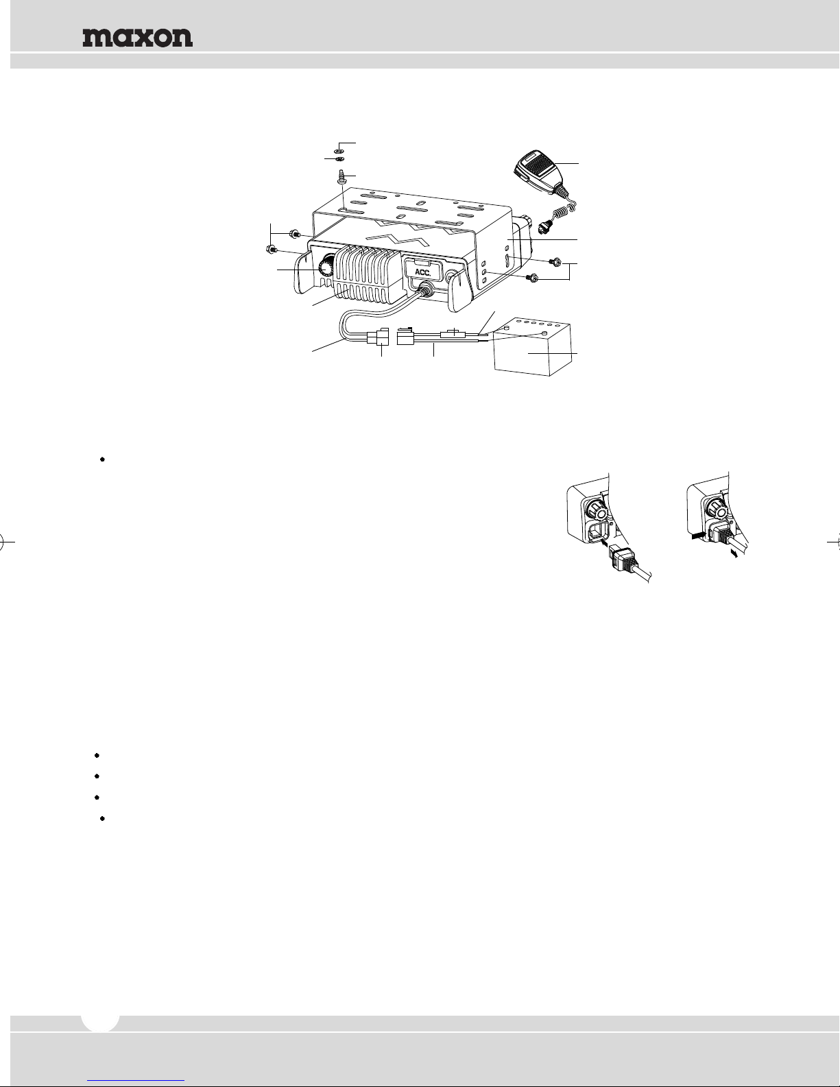
Spring Washer
M4 x 6mm
Hex-headed Screw
Flat Washer
5x16mm
Self-tapping Screw
Microphone
Mounting Bracket
Antenna Connector
Heat Sink
(Aluminum Diecasting)
DC Power Cable
Power Input
Connector
Red(+) Cable
Fuse
Black(-) Cable
M4 x 6mm
Hex-headed Screw
12V Vehicle Battery
Connecting Microphone
1. Insert the microphone plug into jack on the front panel of the transceiver.
Be sure the tab on the microphone plug is facing the left hand side (Figure 1-2).
2. Mount the microphone on the microphone hanger where it will be
within easy reach of the user.
3. To remove the microphone plug, press the tab on the connector
while pulling the plug out of the transceiver jack.
Figure 1-2) Installation and Removing of the Microphone
Supplied Accessories
Carefully unpack the transceiver and check that the items listed below are included in the package.
DC power cable with 15A Fuse ............................................................................................................. 1
Mounting Bracket .................................................................................................................................... 1
Screw set
5 x 16 mm self-tapping screw .......................................................................................................... 4
Hex-headed screw with washer ...................................................................................................... 4
Spring washer ....................................................................................................................................4
Flat washer ...................................................................................................................................... 4
Microphone (with cable) ......................................................................................................................... 1
Microphone hanger (with 4 x16 mm self-tapping screws) .................................................................... 1
User manual ............................................................................................................................................ 1
4

www.maxonamerica.com
2. Features
The followings are the main features of the TM-2000 / TM-8000 Series Mobile Radio:
128 x 32 Dots Graphic LCD
512 Channels and 32 Groups are Selectable.
External Squelch Control
Channel Spacing: 12.5 / 25kHz (12.5kHz for USA)
Wide Band Coverage (VHF: 136~174MHz; UHF: 400~470, 450~520MHz)
Call Guard Squelch of Standardized CTCSS / DCS
Identification Origination (2 Tone and 5 Tone)
Built-in Scrambler (Voice Inversion Type)
Built-in Compander (Compressor and Expander)
GPS Data Communication (Option)
Normal Scanning / Priority Scanning
BCL (Busy Channel Lock) / BCLO (Busy Channel Lock Override)
5W / 10W / 20W / 40W (UHF) / 50W (VHF) Power Switchable - TM-8000 Series
5W / 10W / 25W - TM-2000 Series
Selectable Squelch Level (0~10)
Time-Out Timer (TOT)
Standard DTMF Encode and DTMF Decoder with ANI Function
Programmable Home Channel Function
Emergency & Built-in Emergency Microphone
Talk Around
Internal or External Speaker
Remote Radio Stun / Revive (Uses 5 tone)
Ignition Function / Horn Alert / Public Address
4W Front-Mounted Speaker
Heavy-Duty Microphone
Various Parameters and PC Downloading Methods
Built-in D-SUB15 Accessory Connector
PC Program Tuning
5
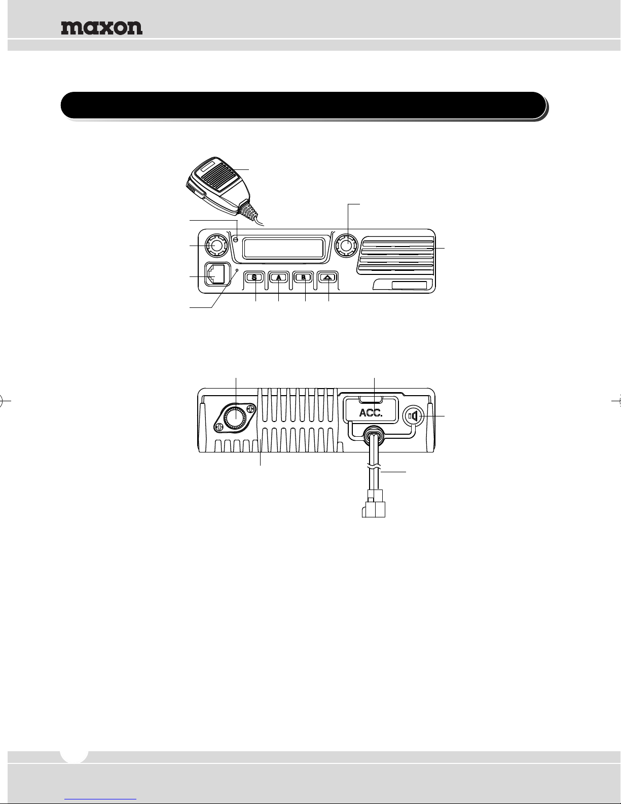
3. Appearance of TM-2000 / TM-8000 Series Mobile Radio
Hand MIC
Enter Switch
TX/RX Status LED
Channel UP/DOWN Selection / Group Selection
Power ON/OFF
Volume Switch
MIC Jack
Emergency MIC
Speaker
Programmable Function Buttons
15 Pin Accessory ConnectorAntenna Connector
EXT Speaker Jack
DC Power CableHeat Sink
(Aluminum Diecasting)
Figure 4-1) Appearance TM-2000 / TM-8000 Series
6
4. Controls & Keys
Welcome SC NM Team 1
001
CH 001
www.maxonamerica.com
Display
Power ON/OFF
Volume Switch
MIC Jack
Emergency MIC
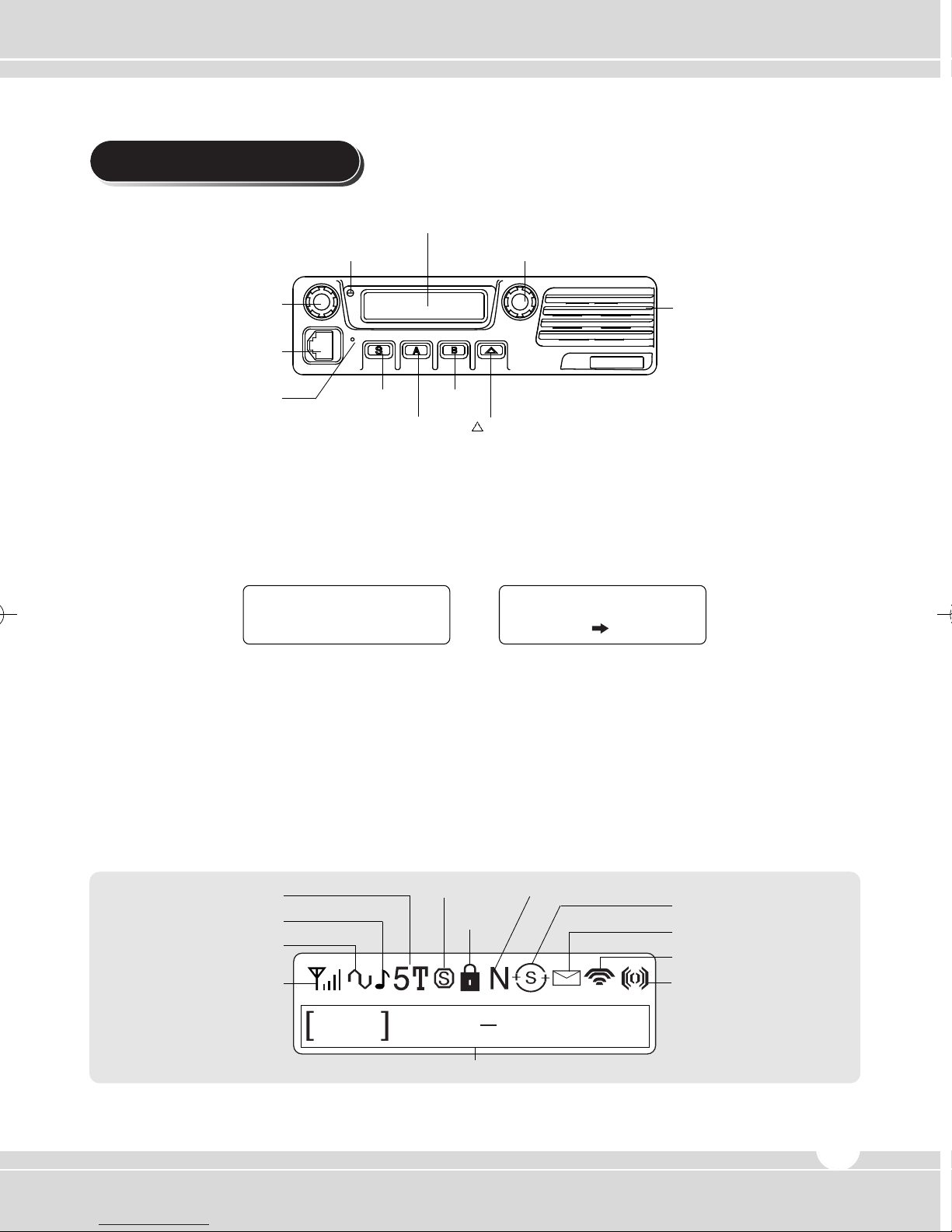
Figure 5-1) TM-2102 / TM-2402 / TM-8102 / TM-8402 Front Panel
TX/RX Status LED
S Key
Channel UP/DOWN Selection / Group Selection
B Key
A Key
Key
Speaker
Power ON / OFF Volume Switch & Squelch Control
Press and hold the knob over 2 seconds to turn the mobile radio on and off.
Rotate to adjust the volume level from 1 to 16. Turn it clockwise to increase the volume and
counterclockwise to decrease the volume.
When the knob is pushed less than 2 seconds, Squelch can be changed.
Display
128 x 32 Dots Graphic LCD. Each icon indicates related operation.
2/5 TONE
Alert ON/OFF
CTCSS/DCS
RSSI
Display
Figure 5-2) TM-2000 / TM-8000 Series LCD Indicator
Scramble Narrow/Wide
Key Lock
Channel & Status Display
Scan
Status
RF Power Level
Compander
7
 Loading...