

Maxon TE-25DC, TEWR-33, TE-33, TEWR-25DC Installation Manual
M-17-10
REV . A
JULY 2018
To fi nd maintenance & parts information for your TE-25DC or TE-33 Liftgate, go to
www.maxonlift.com. Click the PRODUCTS, TUK-A-WAY & TE-25DC/TE-33 buttons. Open the
Maintenance Manual in the PRODUCT DOCUMENTATION window. For parts, click on the
PARTS PORTAL, TUK-A-WAY & TE-25DC/TE-33 buttons.
© 2018 MAXON Lift Corp.

TABLE OF CONTENTS
SUMMARY OF CHANGES: M-17-10, REVISION A ............................................................. 4
WARNINGS ........................................................................................................................... 5
SAFETY INSTRUCTIONS ....................................................................................................6
NOTICE .................................................................................................................................6
STANDARD LIFTGATE COMPONENTS .............................................................................. 7
TE-25DC & TE-33 INSTALLATION PARTS BOXES ............................................................. 8
TE-25DC & TE-33 MANUALS & DECALS ............................................................................ 9
VEHICLE REQUIREMENTS ............................................................................................... 10
CENTER OF MASS ............................................................................................................16
STEP 1 - ATTACH EXTENSION PLATE TO VEHICLE ....................................................... 17
BOLT EXTENSION PLATE .................................................................................. 17
WELD EXTENSION PLATE (ALTERNATE METHOD) ........................................ 20
STEP 2 - WELD LIFTGATE TO VEHICLE .......................................................................... 22
STEP 3 - ATTACH OPTIONAL BATTERY BOX & FRAME TO VEHICLE (IF EQUIPPED) . 28
STEP 4 - RUN POWER CABLE .......................................................................................... 36
STEP 5 - CONNECT POWER CABLE ................................................................................ 38
STEP 6 - CONNECT GROUND CABLE ............................................................................. 40
STEP 7 - INSTALL CONTROL SWITCH ............................................................................. 41
STEP 8 - CHECKING HYDRAULIC FLUID ......................................................................... 43
STEP 9 - CONNECT POWER CABLE TO BATTERY ......................................................... 45
STEP 10 - REMOVE LOCKING BRACKETS & CHECK FOR INTERFERENCE ............... 46
STEP 11 - ADJUST PLATFORM OPENER ......................................................................... 51
STEP 12 - ADJUST PLATFORM (IF REQUIRED) .............................................................. 53
STEP 13 - FINISH WELDING LIFTGATE TO VEHICLE ..................................................... 55
STEP 14 - BOLT OPTIONAL STEPS TO EXTENSION PLATE ......................................... 56
STEP 15 - VEHICLE TAILLIGHT POSITIONING ............................................................... 60
ATTACH DECALS: TE-25DC & TE-33 ............................................................................... 61

TABLE OF CONTENTS - Continued
DECALS & PLATES ........................................................................................................... 63
ATTACH DECALS: TEWR-25DC & TEWR-33 ................................................................... 64
DECALS & PLATES ........................................................................................................... 66
TOUCHUP PAINTED OR GALVANIZED FINISH ...............................................................67
SYSTEM DIAGRAMS .........................................................................................................68
PUMP & MOTOR SOLENOID OPERATION (GRAVITY DOWN) ........................................ 68
HYDRAULIC SCHEMATIC (GRAVITY DOWN) ................................................................... 69
ELECTRICAL SCHEMATIC (GRAVITY DOWN) ................................................................. 70
PUMP & MOTOR SOLENOID OPERATION (POWER DOWN) .......................................... 71
HYDRAULIC SCHEMATIC (POWER DOWN) .................................................................... 72
ELECTRICAL SCHEMATIC (POWER DOWN) ................................................................... 73
ELECTRICAL VALUES........................................................................................................ 74
OPTIONS ........................................................................................................................... 75
OPTIONAL LIFTGATE COMPONENTS .............................................................................. 75

SUMMARY OF CHANGES: M-17-10, REVISION A
PAGE DESCRIPTION OF CHANGE
Cover Updated REV, date of release, and models. TE-25DC & TEWR-25DC were added.
Various
9
41 FIG. 41-2 shows new control switch.
57 FIG. 57-1 shows new carriage bolts for bolting on dual steps.
60 Updated taillights installation instructions.
61,64 Added new bilingual UP/DOWN decals and removed old UP & DOWN decal.
62,65 Added table for 2500 lb and 3300 lb capacity decals.
74 Updated electrical values table to include cycle counter operation voltage.
Added TE-25DC and TEWR-25DC throughout the manual with topics & instructions
about TE-33 & TEWR-33 liftgates.
Table added with new manual & decal kit for TE-25DC. Old decals P/N 264507
were removed. New bilingual decals P/N 299038-01 were added.

Comply with the following WARNINGS and SAFETY INSTRUCTIONS while installing
Liftgates. See Operation Manual for operating safety requirements.
WARNINGS
• Do not stand, or allow obstructions, under the platform when lowering the Liftgate. Be sure your
feet are clear of the Liftgate.
• Keep fi ngers, hands, arms, legs, and feet clear of moving Liftgate parts (and platform
edges) when operating the Liftgate.
• Correctly stow platform when not in use. Extended platforms could create a hazard for
people and vehicles passing by.
• Make sure vehicle battery power is disconnected while installing Liftgate. Connect vehicle
battery power to the Liftgate only when installation is complete or as required in the installation
instructions.
• If it is necessary to stand on the platform while operating the Liftgate, keep your feet and any
objects clear of the inboard edge of the platform. Your feet or objects on the platform can become
trapped between the platform and the Liftgate extension plate.
• Never perform unauthorized modifi cations on the Liftgate. Modifi cations may result in early failure
of the Liftgate and may create hazards for Liftgate operators and maintainers.
• Recommended practices for welding on steel parts are contained in the current AWS (American
Welding Society) D1.1 Structural Welding Code - Steel. Damage to Liftgate and/or vehicle, and
personal injury can result from welds that are done incorrectly.
!
WARNING
• Recommended practices for welding galvanized steel are contained in the current AWS (American Welding Society) D19.0 Welding Zinc-Coated Steel. Damage to Liftgate and/or vehicle,
and personal injury can result from welds that are done incorrectly.
11921 Slauson Ave. Santa Fe Springs, CA. 90670 (800) 227-4116 FAX (888) 771-7713
5

SAFETY INSTRUCTIONS
• Read and understand the instructions in this Installation Manual before installing Liftgate.
• Before operating the Liftgate, read and understand the operating instructions in Operation
Manual.
• Comply with all WARNING and instruction decals attached to the Liftgate.
• Keep decals clean and legible. If decals are illegible or missing, replace them. Free replacement
decals are available from Maxon Customer Service.
• Consider the safety and location of bystanders and location of nearby objects when operating the
Liftgate. Stand to one side of the platform while operating the Liftgate.
• Do not allow untrained persons to operate the Liftgate.
• Wear appropriate safety equipment such as protective eyeglasses, faceshield and clothing while
performing maintenance on the Liftgate and handling the battery. Debris from drilling and contact
with battery acid may injure unprotected eyes and skin.
• Be careful working by an automotive type battery. Make sure the work area is well ventilated and
there are no fl ames or sparks near the battery. Never lay objects on the battery that can short the
terminals together. If battery acid gets in your eyes, immediately seek fi rst aid. If acid gets on your
skin, immediately wash it off with soap and water.
• If an emergency situation arises (vehicle or Liftgate) while operating the Liftgate, release the con-
trol switch to stop the Liftgate.
SAFETY INSTRUCTIONS
• A correctly installed Liftgate operates smoothly and reasonably quiet. The only noticeable noise
during operation comes from the power unit while the platform is raised and lowered. Listen for
scraping, grating and binding noises and correct the problem before continuing to operate Liftgate.
NOTICE
NOTICE
• Maxon Lift is responsible for the instructions to correctly install MAXON Liftgates on
trucks or trailers only.
• Liftgate installers, not Maxon Lift, are responsible for reviewing and complying with all
applicable Federal, State, and Local regulations pertaining to the trailer or truck.
• Installers of the liftgate should ensure that all trucks and trailers are equipped with grab
handles as needed. Refer to Technology Maintenance Council (TMC) RP 1428: Entry
and Egress Guidelines for Vehicles With Fold-Under Type Liftgates.
11921 Slauson Ave. Santa Fe Springs, CA. 90670 (800) 227-4116 FAX (888) 771-7713
6
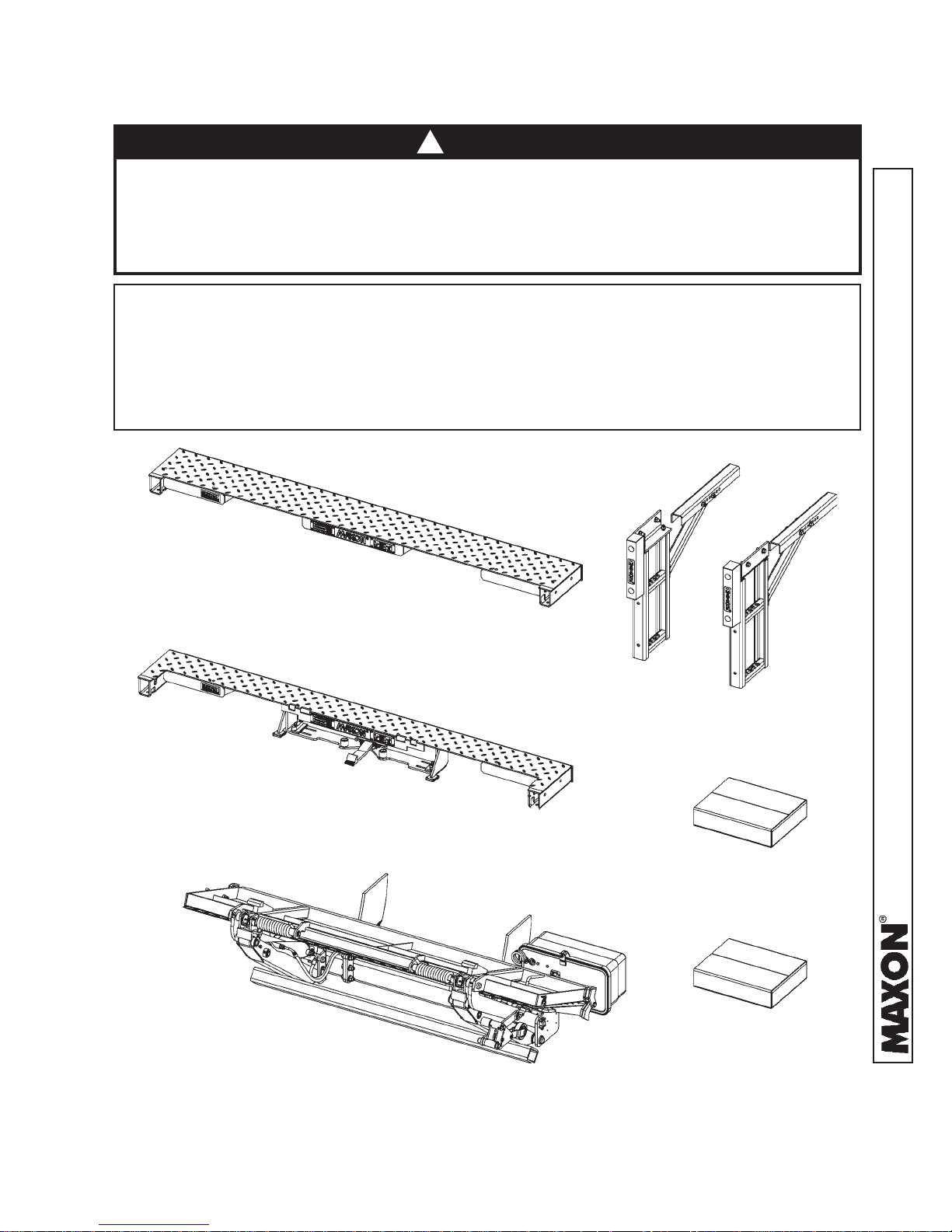
STANDARD LIFTGATE COMPONENTS
!
CAUTION
Unpacking the Liftgate on unlevel surface may allow heavy components to slide off
when shipping bands are cut. Injury and equipment damage could result. Before
the shipping bands are cut, put Liftgate on level asphalt, concrete or compacted
dirt surface that will support 1500 lb. When unpacking the Liftgate, remove heavy
components carefully to avoid injury and damage.
NOTE: Make sure you have all components and parts before you start installing Liftgate.
Compare parts in the part box and each kit box with packing list enclosed in each
box. If parts and components are missing or incorrect, call:
Maxon Customer Service
Call (800) 227-4116 or
Send e-mail to cservice@maxonlift.com
EXTENSION PLATE
EXTENSION PLATE FOR WALK RAMP
DUAL STEP KIT
PARTS BOX B
11921 Slauson Ave. Santa Fe Springs, CA. 90670 (800) 227-4116 FAX (888) 771-7713
PARTS BOX A OR C
TE-25DC OR TE-33 LIFTGATE
LIFTGATE COMPONENTS
FIG. 7-1
7
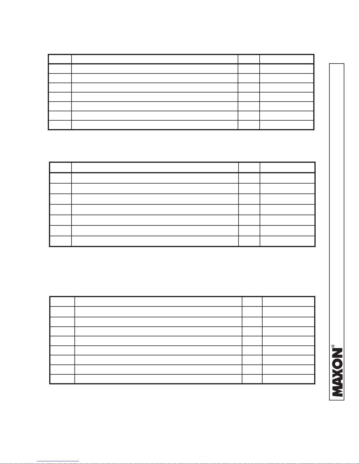
TE-25DC & TE-33 INSTALLATION PARTS BOXES
ITEM NOMENCLATURE OR DESCRIPTION QTY. PART NUMBER
REF PARTS BOX A 1 297502-01
1 SPRING CLIP 10 050079
2 PLASTIC TIE 2 206864
3 #10 LOOM CLAMP 2 801681
4 SCREW TAPPING #10 X 1/2” LG. 2 030458
5 CABLE ASSEMBLY, 2 GA, 48” LG. 1 251871-26
6 CABLE ASSEMBLY, 175 AMPS, 38’ LG. 1 264422
CONTENTS OF PARTS BOX A
TABLE 8-1
ITEM NOMENCLATURE OR DESCRIPTION QTY. PART NUMBER
REF PARTS BOX B 1 297049-01
1 TOGGLE SWITCH ASSEMBLY 1 296855-01
2 HEX NUT, 1/2”-13 2 901011-9
3 HEX HEAD CAP SCREW, 1/2”-13 X 1-1/2” LG. 2 900035-3
4 INSTALLATION BRACKET 2 269462-01
5 SCREW, SELF TAPPING, #10-24 X 1-1/2” LG. 2 900057-7
6 LUG, 2 GA COPPER 1 906497-02
CONTENTS OF PARTS BOX B
TABLE 8-2
ITEM NOMENCLATURE OR DESCRIPTION QTY. PART NUMBER
REF PARTS BOX C 1 297502-02
1 SPRING CLIP 20 050079
2 PLASTIC TIE 4 206864
3 GROMMET, 1” DIAMETER, 2 HOLES 1 266428-09
4 CABLE ASSEMBLY, 175 AMP 38’ LG. 1 264422
5 GROUND CABLE ASSEMBLY, 2 GA X 38’ LG. 1 269191-01
6 SCREW TAPPING #10 X 1/2” LG. 2 030458
7 #10 LOOM CLAMP 2 801681
11921 Slauson Ave. Santa Fe Springs, CA. 90670 (800) 227-4116 FAX (888) 771-7713
CONTENTS OF PARTS BOX C
TABLE 8-3
8
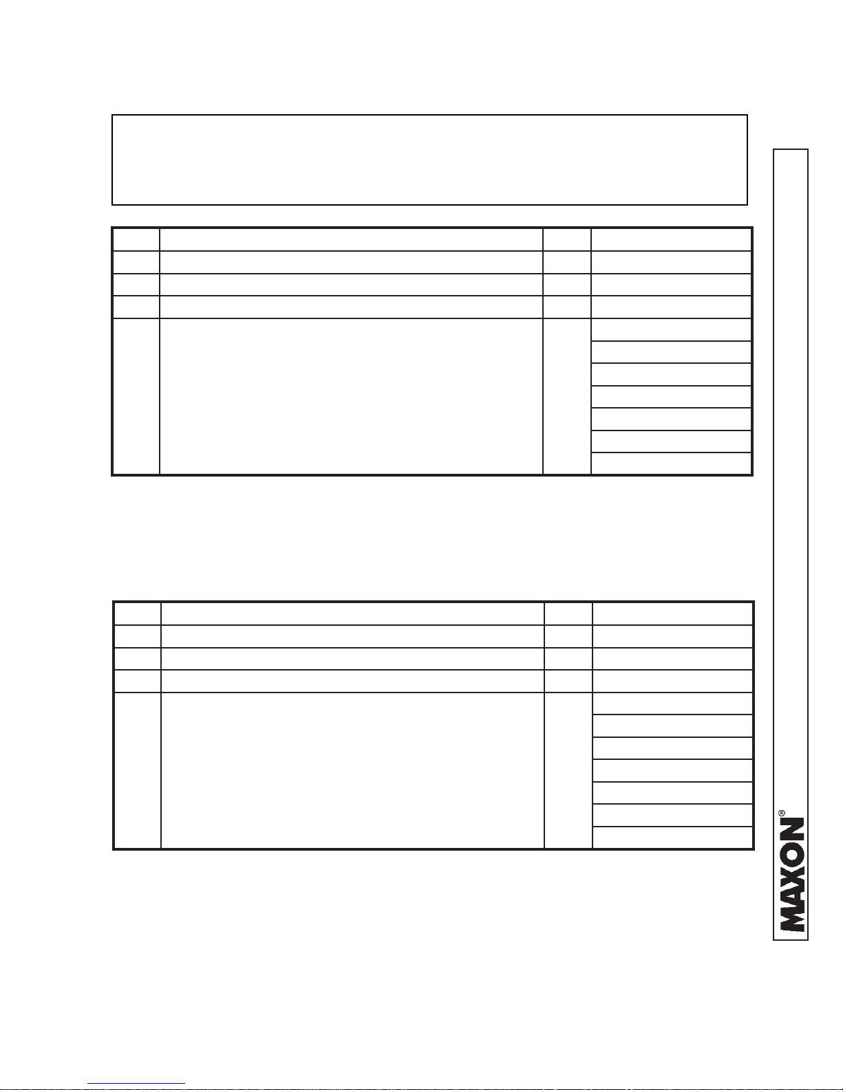
TE-25DC & TE-33 MANUALS & DECALS
To fi nd maintenance & parts information for your TE-25DC or TE-33 Liftgate, go to
www.maxonlift.com. Click the PRODUCTS, TUK-A-WAY & TE-25DC/TE-33 buttons.
Open the Maintenance Manual in the PRODUCT DOCUMENTATION window. For
parts, click on the PARTS PORTAL, TUK-A-WAY & TE-25DC/TE-33 buttons.
ITEM NOMENCLATURE OR DESCRIPTION QTY. PART NUMBER
REF TE-25DC MANUAL & DECAL KIT 1 298270-02
1 INSTALLATION MANUAL 1 M-17-10
2 OPERATION MANUAL 1 M-17-11
220382
299038-01
266013-02
3 DECALS (SEE DECAL PAGES IN THIS MANUAL) 1
282522-01
282847-02
265441-01
285800-01
TE-25DC STANDARD KIT
TABLE 9-1
ITEM NOMENCLATURE OR DESCRIPTION QTY. PART NUMBER
REF TE-33 MANUAL & DECAL KIT 1 298270-01
1 INSTALLATION MANUAL 1 M-17-10
2 OPERATION MANUAL 1 M-17-11
220388-02
299038-01
266013-02
3 DECALS (SEE DECAL PAGES IN THIS MANUAL) 1
282522-01
282847-02
265441-01
285800-01
TE-33 STANDARD KIT
TABLE 9-2
11921 Slauson Ave. Santa Fe Springs, CA. 90670 (800) 227-4116 FAX (888) 771-7713
9
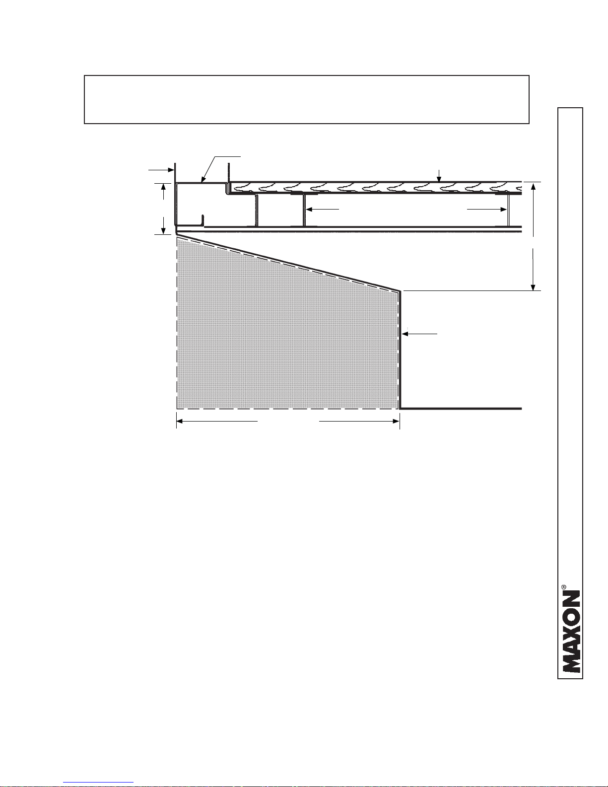
VEHICLE REQUIREMENTS
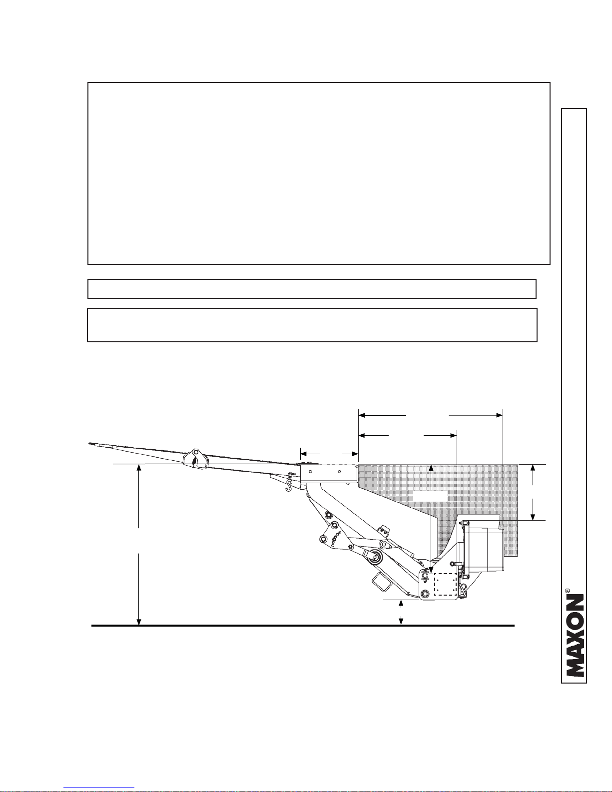
NOTE: Maximum and Minimum Operating Bed Height for Standard Platforms:
• Maximum bed height for TE-25DC & TE-33 Liftgates on high bed vehicles is 54”
(unloaded). Minimum bed height is 42” (loaded).
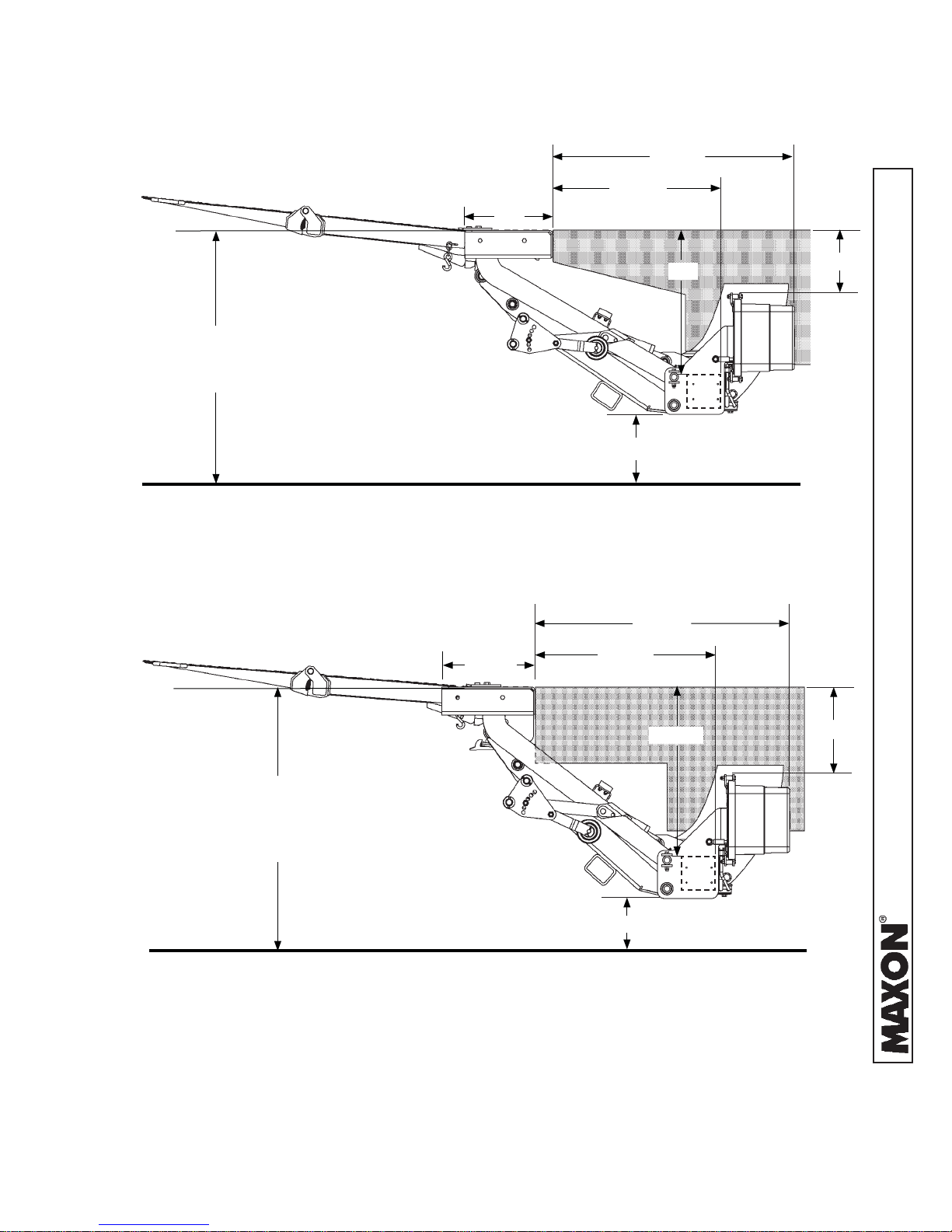
• Maximum bed height for TE-25DC & TE-33 Liftgates on low bed vehicles is 44”
(unloaded). Minimum bed height varies with platform depth. See TE-25DC & TE-33
LOW BED CLEARANCES, FIG. 11-1.
• Maximum bed height for TEWR-25 & TEWR-33 walk ramp Liftgates is 54” (unloaded). Minimum bed height varies with platform depth. See TEWR-25DC &
TEWR-33 CLEARANCES, FIG. 11-2.
If swing door latches interfere with fi t of extension plate, do not install this Liftgate
on vehicle bodies equipped with swing open doors.
NOTE: Dimensions are provided as reference for fi tting Liftgate to vehicle body.
NOTE: Make sure vehicle is parked on level ground while preparing vehicle and
installing Liftgate.
1. Check for correct clearances (FIGS. 10-1, 11-1, and 11-2)
vehicle to prevent interference between vehicle and Liftgate.
13”
54” MAX BED HEIGHT
42” MIN BED HEIGHT
23-1/2” TO 11-1/2”
on
32-11/16”
22-1/8”
24-1/2”
12-5/8”
11921 Slauson Ave. Santa Fe Springs, CA. 90670 (800) 227-4116 FAX (888) 771-7713
TE-25DC & TE-33 HIGH BED CLEARANCES
(54” TO 42” BED HEIGHT)
FIG. 10-1
10
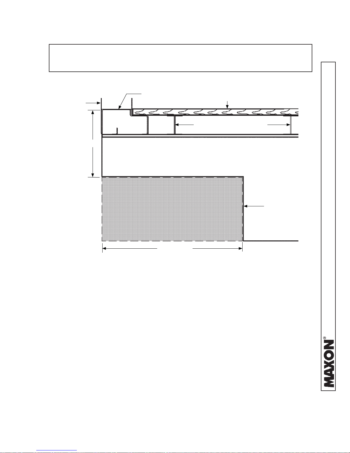
VEHICLE REQUIREMENTS - Continued
35-1/2”
24-7/8”
13”
44” MAX BED HEIGHT (ALL PLATFORMS)
40” MIN BED HEIGHT (52” X 84” PLATFORMS ONLY)
38” MIN BED HEIGHT (48” X 84” PLATFORMS ONLY)
TE-25DC & TE-33 LOW BED CLEARANCES
(44” TO 38” BED HEIGHT)
FIG. 11-1
13-1/2”
21”
16-7/8” TO 10-7/8”
36-5/8”
26-1/8”
9-1/4”
TEWR-25DC & TEWR-33 ONLY
54” MAX BED HEIGHT (ALL PLATFORMS)
46” MIN BED HEIGHT (52” X 84” PLATFORMS ONLY)
44” MIN BED HEIGHT (48” X 84” PLATFORMS ONLY)
TEWR-25DC & TEWR-33 (WALK RAMP) CLEARANCES
(44” TO 54” BED HEIGHT)
FIG. 11-2
24-1/2”
22-5/16 TO 12-5/16”
12-5/8”
11921 Slauson Ave. Santa Fe Springs, CA. 90670 (800) 227-4116 FAX (888) 771-7713
11
VEHICLE REQUIREMENTS - Continued
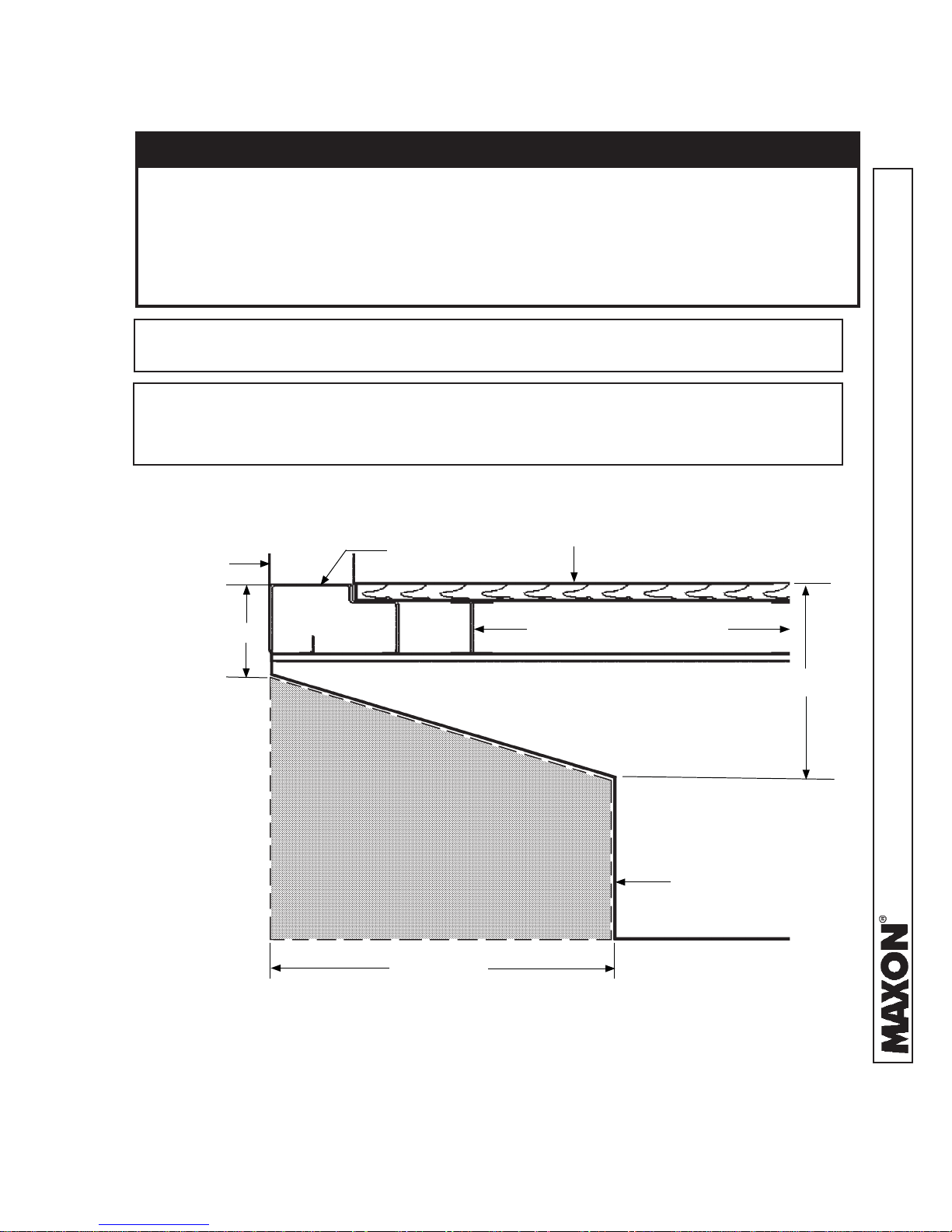
2. Check for correct clearances between walk ramp, walk ramp box, and the extension
plate (FIGS. 12-1A and 12-1B) to prevent interference.
1-1/2”
9-3/16”
27-1/2”
20-1/2”
2-1/4”
EXTENSION PLATE
8-1/2”
WALK RAMP
LATCH
WALK RAMP PAD
(2 PLACES)
25” MIN.
32-1/2” MAX.
(RAMP WIDTH)
WALK RAMP BOX
CLEARANCE DIMENSIONS
(FOR REFERENCE ONLY)
FIG. 12-1B
2-1/4”
NOTCH
(4 PLACES)
1-1/2”
H
SILL
H
RAMP
H
= 8-3/8” - H
RAMP
H
is the height of the vehicle body sill.
SILL
H
is the height of the ramp (max).
RAMP
- 1/8” clearance
SILL
11921 Slauson Ave. Santa Fe Springs, CA. 90670 (800) 227-4116 FAX (888) 771-7713
TEWR-25DC OR TEWR-33 LIFTGATE
SHOWN WITH WALK RAMP BOX
FIG. 12-1A
12
VEHICLE REQUIREMENTS - Continued
CAUTION
• To prevent platform from being damaged, make sure vehicle frame is cut correctly. If the cutouts are incorrect, platform may hit vehicle frame or underbody
when stowing the Liftgate.
• Installer is responsible for ensuring that vehicle body and frame modifi cations
do not adversely affect the integrity of the body and frame.
NOTE: The dimensions, shown in the illustration below, are maximums except as
indicated.
NOTE: The platform cutout area shown below applies to trucks. If the rear sill di-
mension is taller than 5” it may need to be modifi ed. Check with body man-
ufacturer before modifying the rear sill.
3. Fit the Liftgate to vehicle body by cutting vehicle
frame as shown in FIGS. 13-1, 14-1, or 15-1.
TRUCK BODY
5”
REAR SILL
PLATFORM CLEARANCE
CUTOUT AREA
(WITHIN DASHED LINES)
17-7/8” MIN
BODY FLOOR
BODY CROSS MEMBERS
TRUCK
FRAME
12”
11921 Slauson Ave. Santa Fe Springs, CA. 90670 (800) 227-4116 FAX (888) 771-7713
VEHICLE FRAME CUTOUT FOR PLATFORM CLEARANCE
(54” TO 42” BED HEIGHT)
FIG. 13-1
13
VEHICLE REQUIREMENTS - Continued
NOTE: The platform cutout area shown below applies to trucks. If the rear sill di-
mension is taller than 4” it may need to be modifi ed. Check with body
manufacturer before modifying the rear sill.
TRUCK BODY
4”
REAR SILL
PLATFORM CLEARANCE
CUTOUT AREA
(WITHIN DASHED LINES)
19-1/2” MIN
BODY FLOOR
BODY CROSS MEMBERS
9-1/2”
TRUCK
FRAME
VEHICLE FRAME CUTOUT FOR PLATFORM CLEARANCE
(44” TO 38” BED HEIGHT)
FIG. 14-1
11921 Slauson Ave. Santa Fe Springs, CA. 90670 (800) 227-4116 FAX (888) 771-7713
14
VEHICLE REQUIREMENTS - Continued
NOTE: The platform cutout area shown below applies to trucks. If the rear sill dimen-
sion is taller than 9” it may need to be modifi ed. Check with body manufac-
turer before modifying the rear sill.
TRUCK BODY
9”
REAR SILL
BODY CROSS MEMBERS
PLATFORM CLEARANCE
CUTOUT AREA
(WITHIN DASHED LINES)
19” MIN
BODY FLOOR
TRUCK
FRAME
VEHICLE FRAME CUTOUT FOR PLATFORM CLEARANCE
(54” TO 44” BED HEIGHT WITH WALK RAMP)
FIG. 15-1
11921 Slauson Ave. Santa Fe Springs, CA. 90670 (800) 227-4116 FAX (888) 771-7713
15
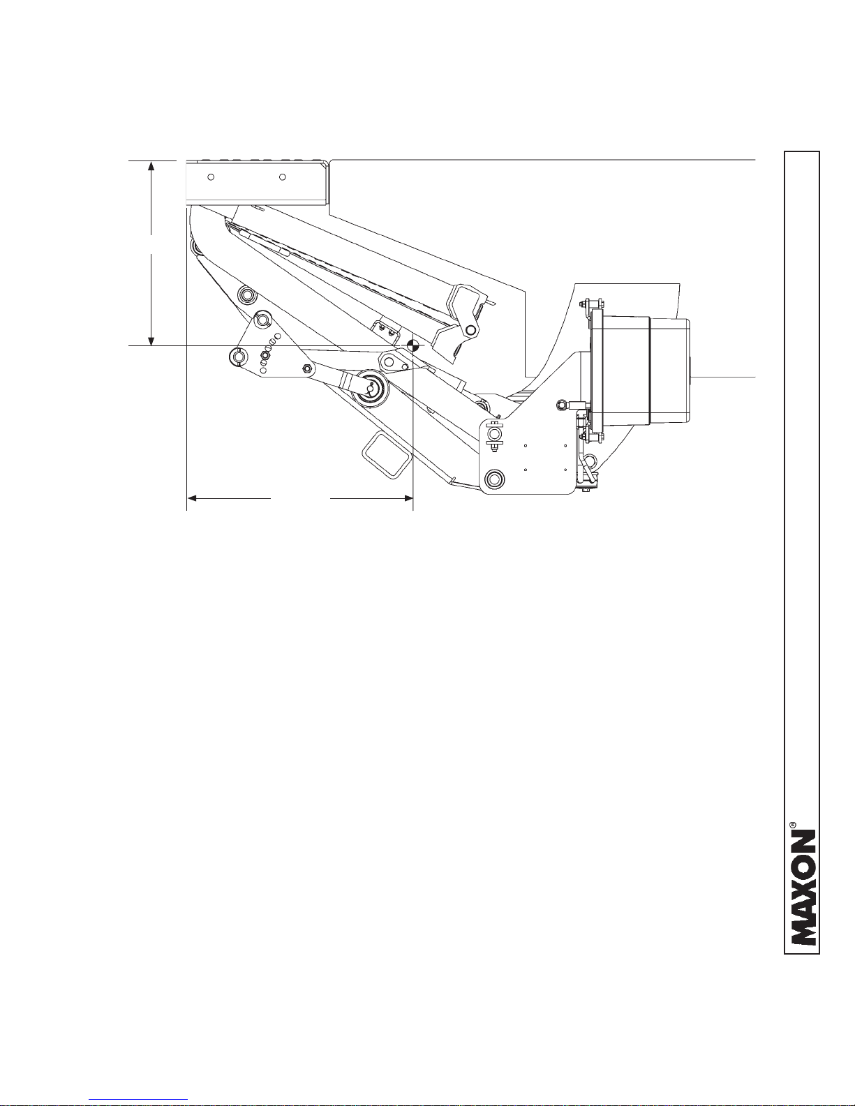
17-9/32”
CENTER OF MASS
21-5/16”
TE-25DC & TE-33 CENTER OF MASS
(STOWED POSITION)
FIG. 16-1
11921 Slauson Ave. Santa Fe Springs, CA. 90670 (800) 227-4116 FAX (888) 771-7713
16
STEP 1 - ATTACH EXTENSION PLATE TO VEHICLE
CAUTION
CAUTION
To preserve the corrosion-resistant properties of the galvanized fi nish,
MAXON recommends bolting the galvanized extension plate to vehicle.
NOTE: TE-25DC & TE-33 Liftgate extension plate comes with bolt holes so it can
be bolted to vehicle body with optional bolt kit. GRADE 8 bolts are required. MAXON recommends getting the optional extension plate hardware
kit listed in OPTIONS section. Vehicle body must be drilled according to
instructions. Extension plate may also be welded to vehicle body. Do the following bolting or welding instructions for the extension plate.
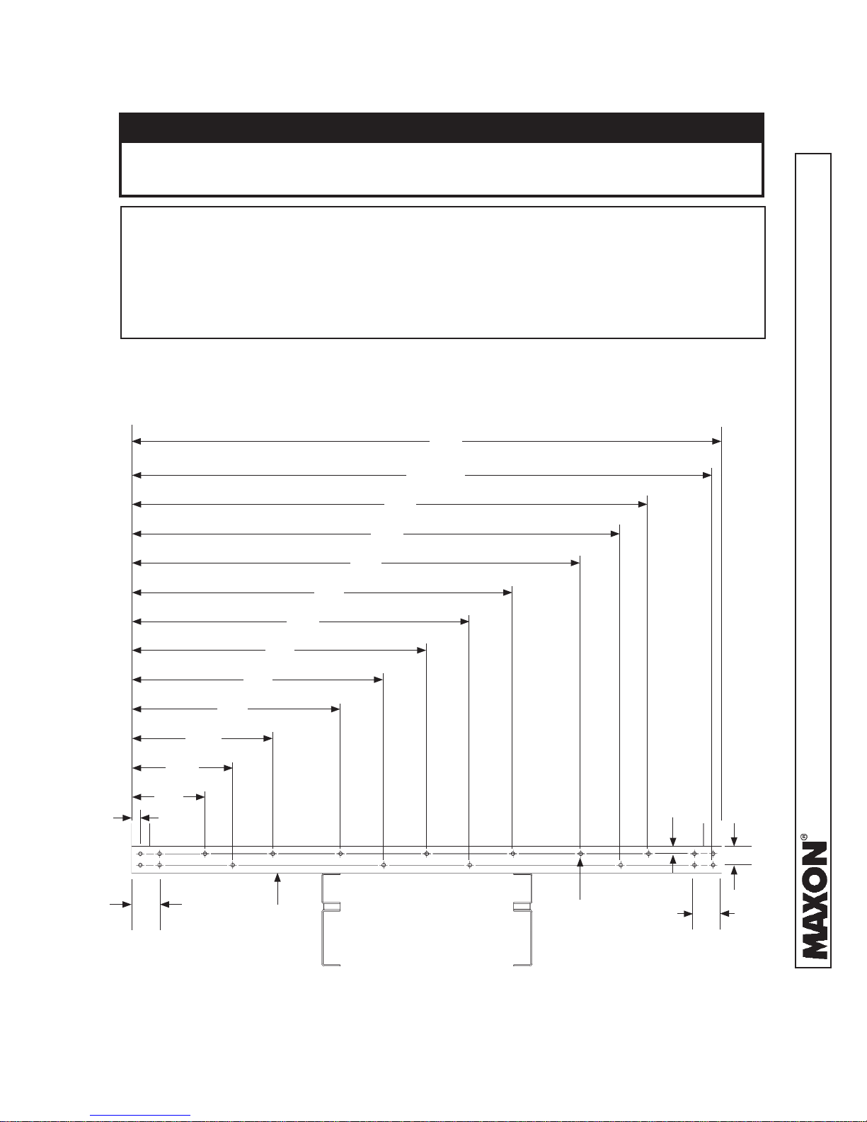
BOLT EXTENSION PLATE
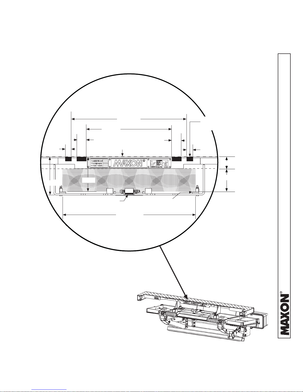
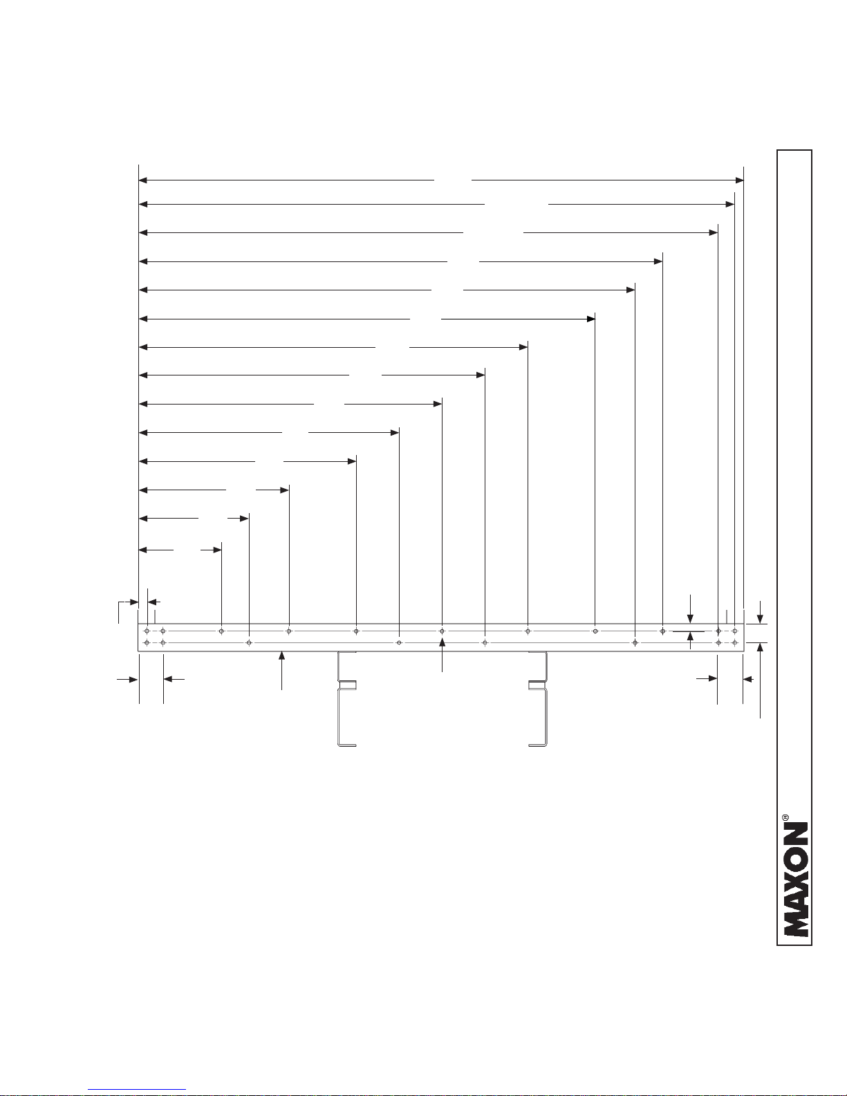
1. Mark and drill holes into rear sill as shown in FIGS. 17-1 and 18-1.
96”
94-1/2”
19”
14”
1-1/2”
24”
6-1/2”
34”
48”
41”
REAR
SILL
55
62”
72”
77”
82”
USE 9/16” DRILL
(19 PLACES)
1-1/4”
11921 Slauson Ave. Santa Fe Springs, CA. 90670 (800) 227-4116 FAX (888) 771-7713
3-1/8”
6-1/2”
REAR SILL - HOLE LOCATIONS FOR 96” WIDE VEHICLE
FIG. 17-1
17
STEP 1 - ATTACH EXTENSION PLATE TO VEHICLE -
Continued
102”
100-1/2”
95-1/2”
85”
80”
75”
65”
58”
51”
44”
37”
1-1/2”
27”
22”
17”
6-1/2”
REAR
SILL
USE 9/16” DRILL
(19 PLACES)
REAR SILL - HOLE LOCATIONS FOR 102” WIDE VEHICLE
FIG. 18-1
1-1/4”
6-1/2”
3-1/8”
11921 Slauson Ave. Santa Fe Springs, CA. 90670 (800) 227-4116 FAX (888) 771-7713
18
STEP 1 - ATTACH EXTENSION PLATE TO VEHICLE -
Continued
CAUTION
CAUTION
The mating surface between the bolt-on extension plate and vehicle rear sill
must be as fl at as possible. Interference between the mating surfaces could
result in a distorted top surface of extension plate when all the bolts are
tightened. Distorted extension plate can also make the dual steps diffi cult to
install correctly. Remove interference or shim rear sill to eliminate or reduce
the possibility of a distorted extension plate.
NOTE: Do not tighten extension plate bolts and lock nuts until:
• All the bolts and lock nuts are in place.
• Mating surfaces of extension plate and rear sill are made fl at as possible.
• Top of extension plate is fl ush with top of rear sill.
NOTE: Weld the LH and RH ends of the extension plate to vehicle body as shown
in FIG. 19-1 if any of the following conditions apply.
• Bolt holes are not accessible on the corner posts of the vehicle body.
• Liftgate will be used for dock loading applications.
• As required by body/trailer manufacturer
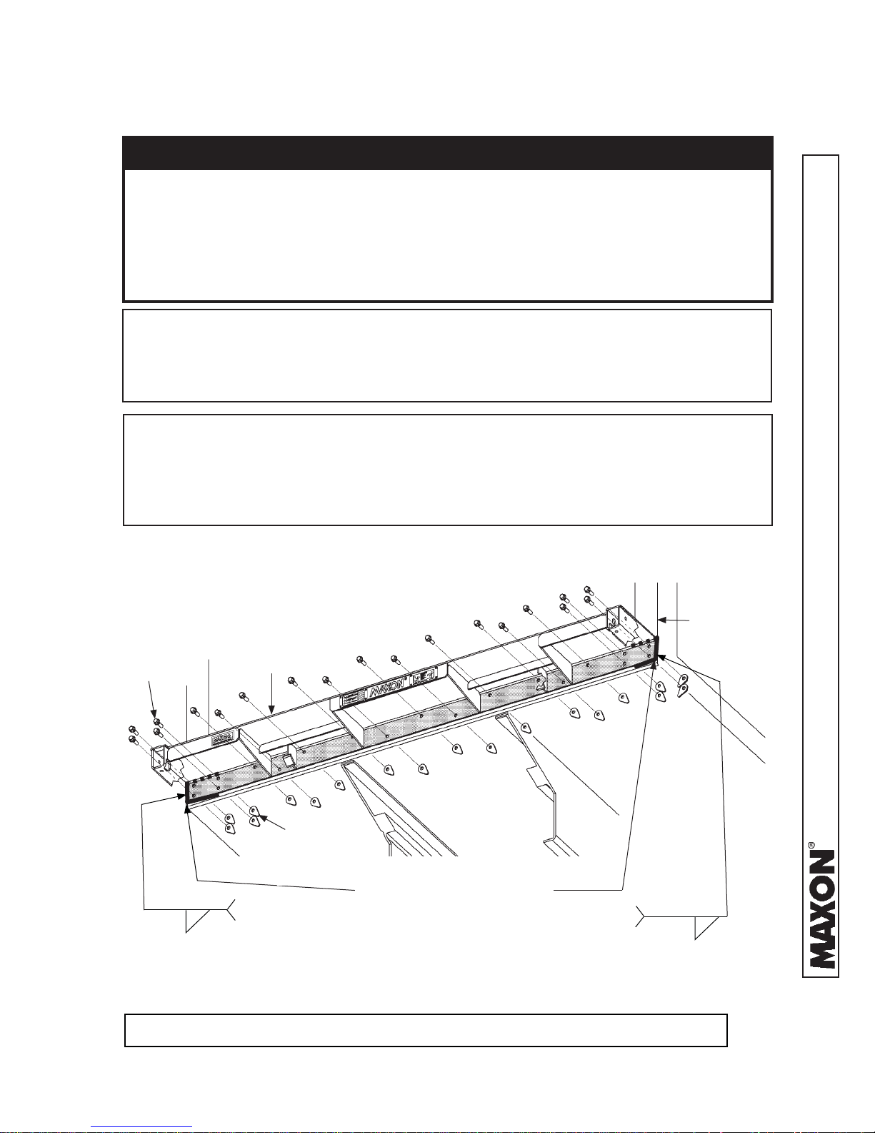
2. Bolt extension plate to vehicle as shown in FIG. 19-1. If necessary, reposition extension
plate so top surface is fl ush with top surface of sill. Then, torque bolts and lock nuts to
105 +/-20 lb-ft.
VEHICLE
BODY
BOLTS
(KIT ITEMS)
3/16”
EXTENSION
PLATE
TEARDROP
LOCK NUTS
(KIT ITEMS)
WRAP WELD
HORIZONTAL
2” MIN/ 6” MAX
WRAP WELD AROUND END
OF EXTENSION PLATE
2” MIN/ 6” MAX
WRAP WELD
HORIZONTAL
3/16”
11921 Slauson Ave. Santa Fe Springs, CA. 90670 (800) 227-4116 FAX (888) 771-7713
BOLTING EXTENSION PLATE (96” WIDE EXTENSION PLATE SHOWN)
NOTE: An optional 102” wide extension kit is available for 102” wide vehicles.
FIG. 19-1
19
STEP 1 - ATTACH EXTENSION PLATE TO VEHICLE -
Continued
WELD EXTENSION PLATE (ALTERNATE METHOD)
CAUTION
To preserve the corrosion-resistant properties of the galvanized fi nish,
MAXON recommends bolting the galvanized extension plate to vehicle.
CAUTION
To protect the original paint system if equipped, a 3” wide area of paint must
be removed from all sides of the weld area before welding.
NOTE: Before welding extension plate to vehicle body, make sure:
• Inboard edge of extension plate is fl ush with the top of sill on vehicle body.
• Top surface of extension plate is level with the ground.
NOTE: For welding galvanized steel, refer to recommended practices as outlined in
AWS (American Welding Society) D19.0 Welding Zinc-Coated Steel.
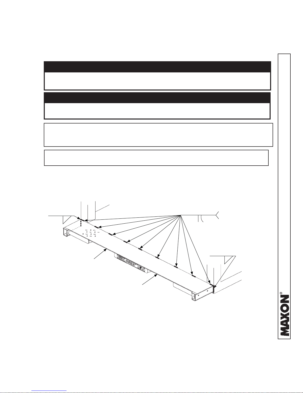
1. Center the extension plate on vehicle body. Before welding extension plate to vehicle
body, make sure top surface of extension plate is fl ush with fl oor of vehicle body.
Weld the extension plate to vehicle body sill as shown in FIGS. 20-1 and 21-1.
3/16”
EXTENSION
PLATE
EXTENSION PLATE WELDS - VIEWED FROM ABOVE
VEHICLE
BODY
FIG. 20-1
3/16”
WELD LENGTH & SPACE:
2” - 11 3/4” (96” WIDE
VEHICLE)
2” - 12 1/2” (102” WIDE
VEHICLE)
3/16”
11921 Slauson Ave. Santa Fe Springs, CA. 90670 (800) 227-4116 FAX (888) 771-7713
20
STEP 1 - ATTACH EXTENSION PLATE TO VEHICLE -
Continued
EXTENSION
PLATE
VEHICLE
BODY
3/16”
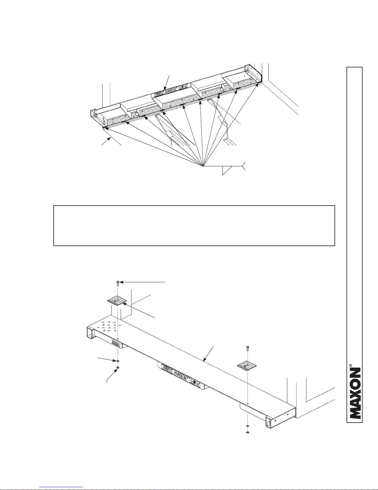
EXTENSION PLATE WELDS - VIEWED FROM UNDERNEATH
FIG. 21-1
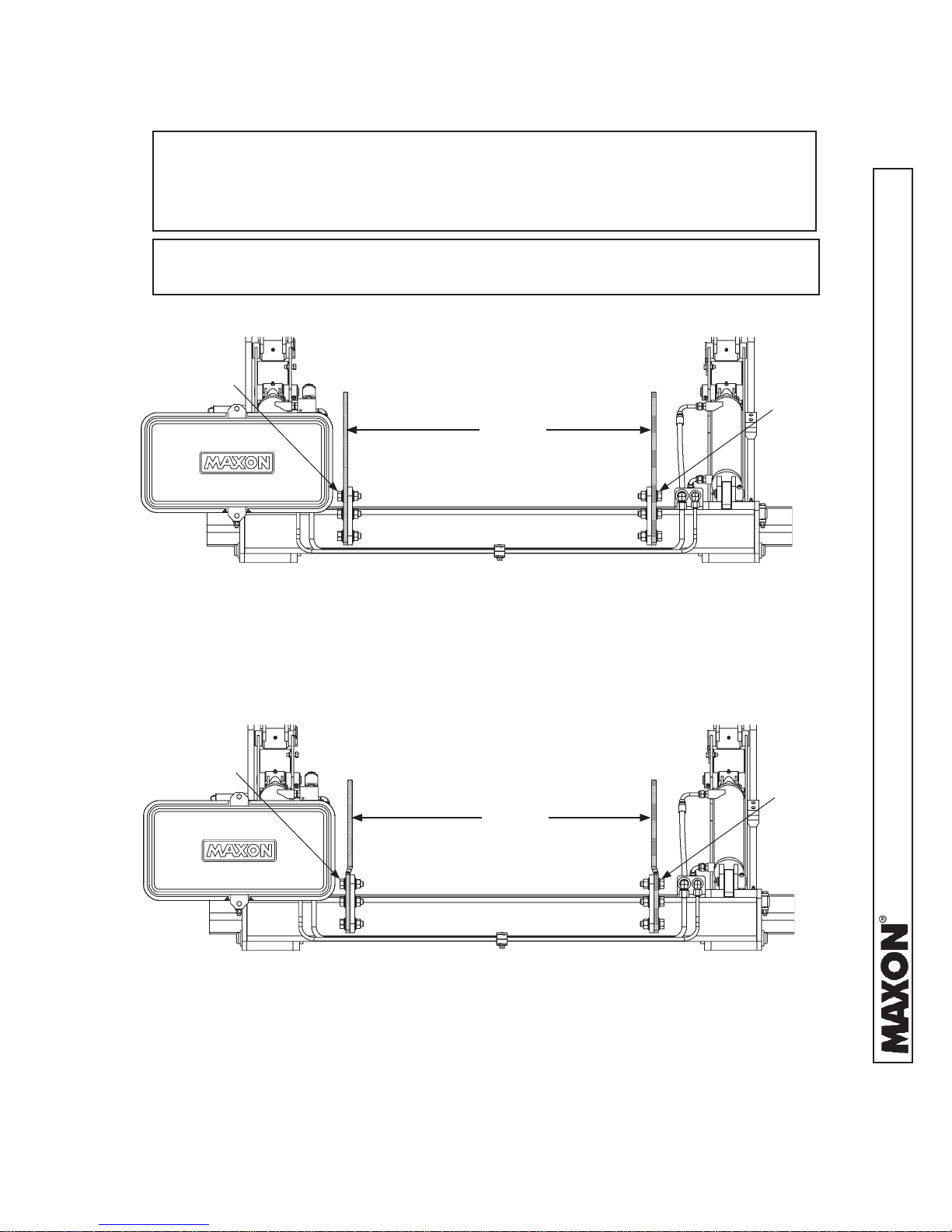
NOTE: During installation of Liftgate, installation brackets keep the heel of the plat-
form level with extension plate and maintain a ¾” gap between extension
plate and heel of platform. The extension plate has bolt holes for bolting on
the installation brackets provided in parts box.
WELD LENGTH & SPACE:
2” - 11 3/4” (96” WIDE VEHICLE)
2” - 12 1/2” (102” WIDE VEHICLE)
2. Bolt 2 installation brackets (parts box items) on the
extension plate as shown in FIG. 21-2. Tighten hex
nuts securely.
CAP SCREW
1/2”-13 X 1-1/2” LG.
(2 PLACES)
BRACKET
(2 PLACES)
EXTENSION
PLATE
FLAT WASHER
1/2”-13
(2 PLACES)
HEX NUT
1/2”-13
(2 PLACES)
11921 Slauson Ave. Santa Fe Springs, CA. 90670 (800) 227-4116 FAX (888) 771-7713
BOLTING ON INSTALLATION BRACKETS
FIG. 21-2
21
STEP 2 - WELD LIFTGATE TO VEHICLE
NOTE: TE-25DC & TE-33 Liftgates are equipped with mounting plates in-
stalled at the factory. Mounting plate widths are shown based upon
truck or trailer frame widths. Ensure you have the correct mounting
plate kit for your application.
NOTE:
BOLT & LOCK
NUT (6 PLACES)
If it’s necessary to unbolt mounting plates from main frame (FIG. 22-1
& FIG. 22-2), torque mounting plate nuts and bolts 220-240 lb-ft.
BOLT &
LOCK NUT
(6 PLACES)
34-1/4”
BOLT-ON MOUNTING PLATES 34-1/4”
FIG. 22-1
BOLT & LOCK
NUT (6 PLACES)
BOLT &
LOCK NUT
(6 PLACES)
33-3/4”
11921 Slauson Ave. Santa Fe Springs, CA. 90670 (800) 227-4116 FAX (888) 771-7713
BOLT-ON MOUNTING PLATES 33-3/4”
FIG. 22-2
22
STEP 2 - WELD LIFTGATE TO VEHICLE - Continued
BOLT &
LOCK NUT
WELD-ON MOUNTING PLATES (PAINTED) TEMPORARILY BOLTED AS SHOWN
FIG. 23-1
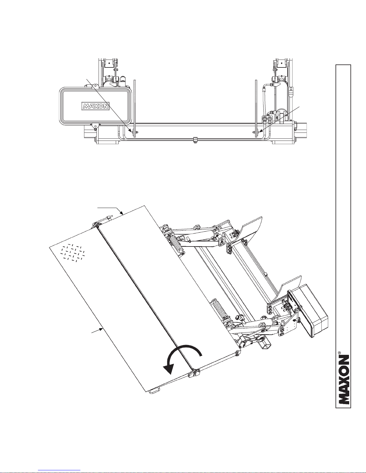
1. Unfold the platform and fl ipover (FIG. 23-2).
PLATFORM
(UNFOLDED)
BOLT &
LOCK NUT
FLIPOVER
(UNFOLDED)
11921 Slauson Ave. Santa Fe Springs, CA. 90670 (800) 227-4116 FAX (888) 771-7713
PLATFORM & FLIPOVER UNFOLDED
FIG. 23-2
23
STEP 2 - WELD LIFTGATE TO VEHICLE - Continued
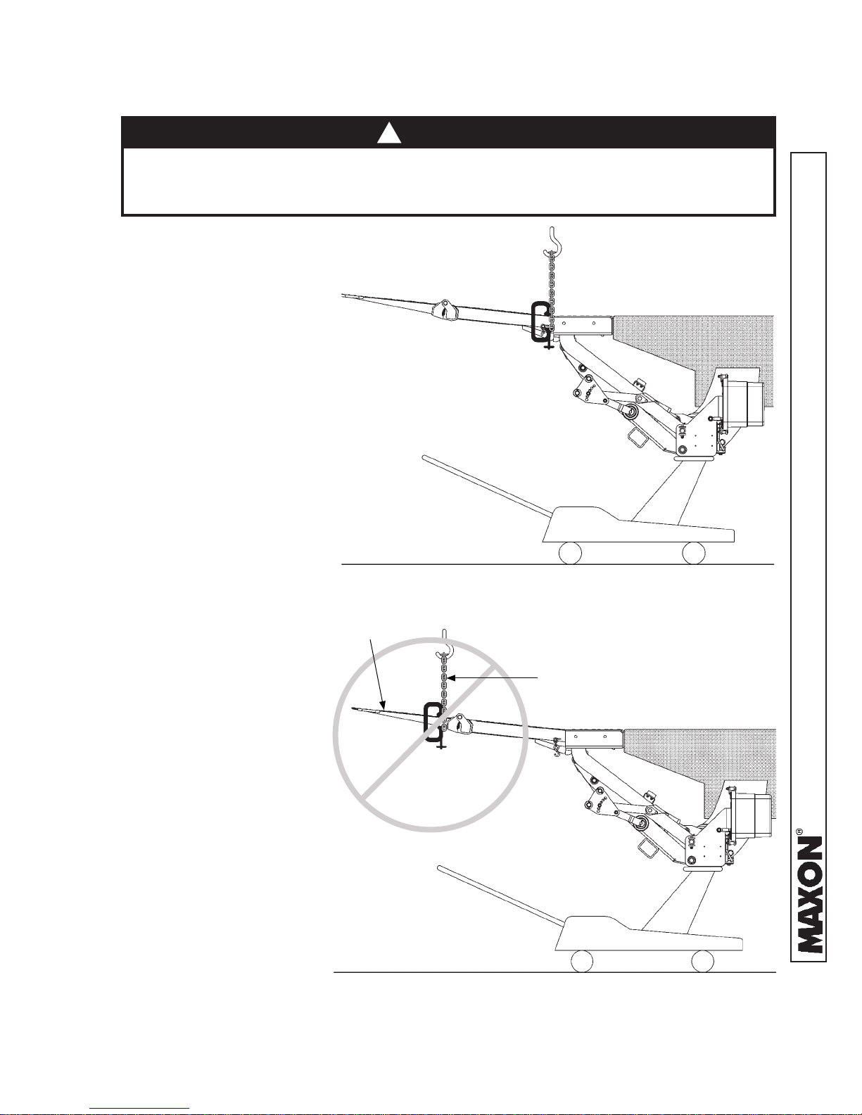
!
CAUTION
To prevent damage to the fl ipover, NEVER hoist the Liftgate by the
fl ipover as shown in the NO illustration. Hoist the Liftgate by the platform only
as shown in the YES illustration.
2. Make sure hoist
is not being set
up the incorrect
way (FIG. 24-2).
Place a “C”clamp on each
side of platform
as shown in FIG.
24-1. (Clamps prevent
hoist chain from slipping off
platform.) Place chain all
around platform (FIG. 24-1).
3. Hoist the Liftgate.
Then, place fl oor jack
under main frame
(FIG. 24-1). Jack the
Liftgate into position.
Make sure vehicle
fl oor is horizontal
and pins are lined up
(FIG. 24-1).
CORRECT WAY TO HOIST LIFTGATE
FIG. 24-1
FLIPOVER
HOIST CHAIN
11921 Slauson Ave. Santa Fe Springs, CA. 90670 (800) 227-4116 FAX (888) 771-7713
INCORRECT WAY TO HOIST LIFTGATE
FIG. 24-2
24
 Loading...