

Page 1

M-11-19
MARCH 2013
OPERATION MANUAL
© 2013 MAXON LIFT CORP.
Page 2

Page 3

TABLE OF CONTENTS
WARNINGS ............................................................................. 4
LIFTGATE TERMINOLOGY .................................................... 6
PAINTED MODELS ................................................................. 6
GALVANIZED MODELS .......................................................... 7
RECOMMENDED DAILY OPERATION CHECKS ................... 8
ATTACH DECALS ................................................................... 10
FORKLIFT ADVISORY ........................................................... 12
ROADSIDE OPERATION ADVISORY .................................... 13
OPERATION ............................................................................ 14
Page 4

4
1. Incorrect operation of this Liftgate can result in serious personal
injury. Comply with WARNINGS and Liftgate operating instructions
in this manual. Do not allow untrained persons or children to operate
the Liftgate. If you need to replace an Operation Manual, additional
copies are available from:
MAXON Lift Corp.
11921 Slauson Ave
Santa Fe Springs, CA 90670
(800) 227-4116
WARNING
!
NOTE: For latest version manuals (and replacements), down-
load manuals from Maxon’s website at www.maxonlift.com.
2. Do not exceed rated load capacity of the Liftgate, which is 2500 lbs.
(2000 lbs. for special Liftgates).
3. Do not allow any part of your body to be placed under, within, or around
any portion of the moving Liftgate or its mechanisms, or in a position
that would trap them between the platform and the fl oor of truck body (or
between platform and the ground) when Liftgate is operating.
4. Consider the safety and location of bystanders and location of nearby
objects when operating the Liftgate. Stand to one side of platform
while operating the Liftgate. Be certain that the area the Liftgate will
move through during operation is clear of all obstacles.
5. Comply with all attached instruction decals and warning decals.
11. Above all, USE GOOD COMMON SENSE when operating this Liftgate.
8. Do not move vehicle unless Liftgate is correctly stowed.
6. Keep decals clean and legible. If decals are illegible or missing, have
them replaced. Get free replacement decals from Maxon.
7. Never drive a forklift on the Liftgate platform.
10. A correctly installed Liftgate will operate smoothly and reasonably
quiet. The only noticeable noise, during Liftgate operation, is from the
power unit while the platform is raised. Listen for scraping, grating and
binding noises and have the problem corrected before continuing to
operate the Liftgate.
9. Correctly stow platform when not in use. Extended platforms can
create a hazard for people and vehicles passing by.
12. Never use a cell phone while operating the Liftgate.
WARNINGS
Page 5

5
THIS PAGE INTENTIONALLY LEFT BLANK
Page 6
6
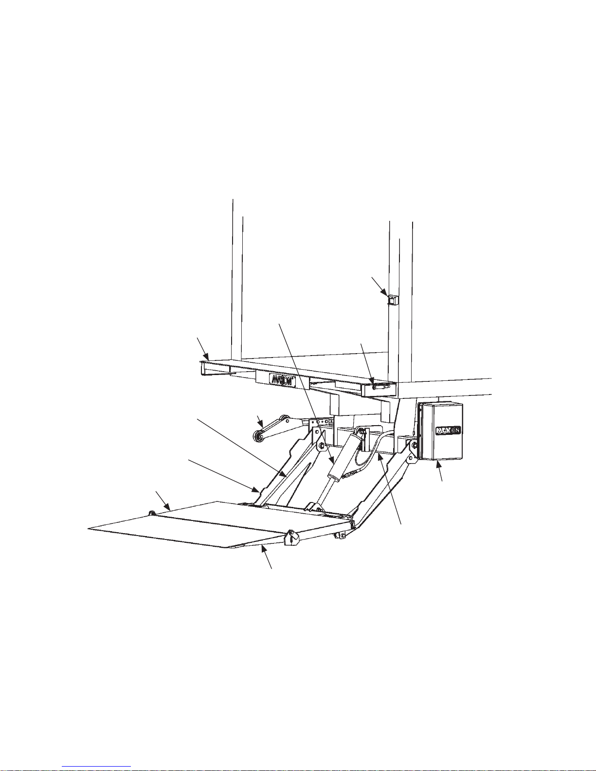
PUMP COVER
LIFT FRAME
P ARALLEL ARM
PLATFORM
LIFT
CYLINDER
EXTENSION
PLATE
MAIN
FRAME
WEDGE FLIPOVER
PLATFORM
OPENER
CONTROL
SWITCH
CONTROL
HANDLE
LIFTGATE TERMINOLOGY
PAINTED MODELS
FIG. 6-1
Page 7
7
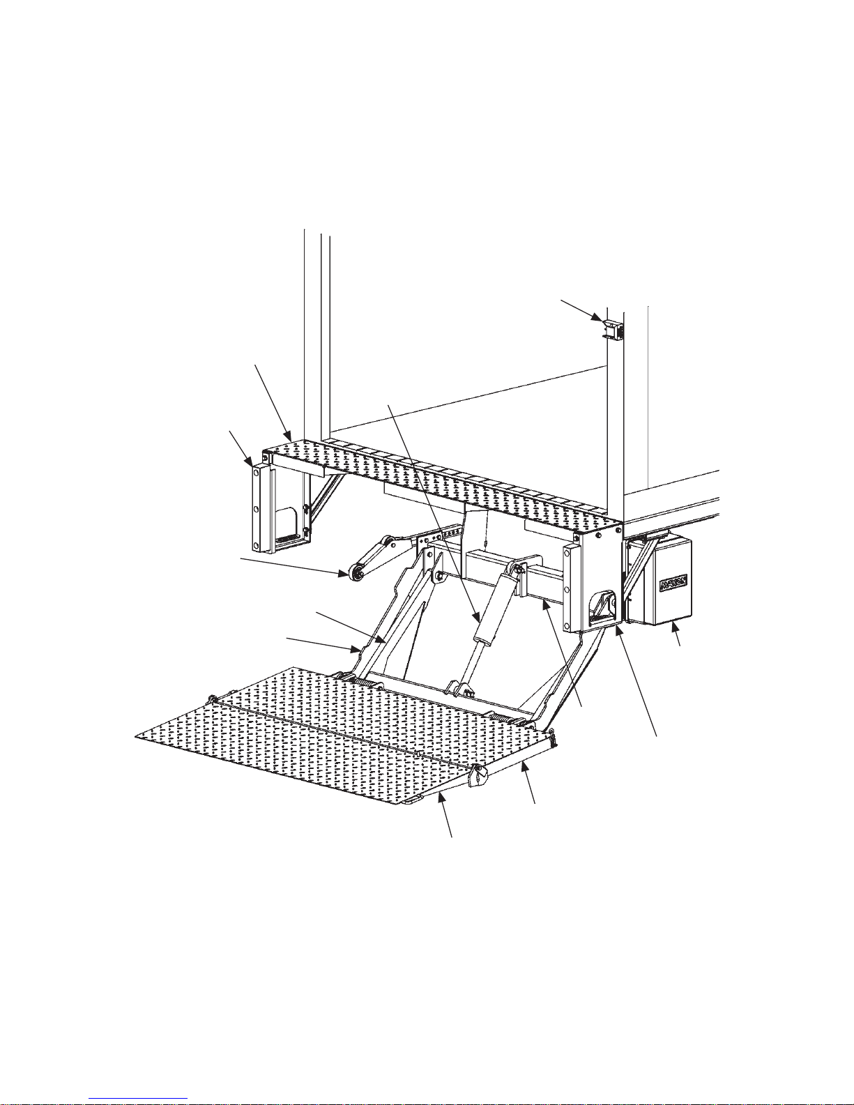
PUMP
COVER
LIFT FRAME
P ARALLEL ARM
PLATFORM
LIFT
CYLINDER
EXTENSION
PLATE
WEDGE FLIPOVER
PLATFORM
OPENER
CONTROL
SWITCH
MAIN
FRAME
STEP
DOCK BUMPER
GALVANIZED MODELS
FIG. 7-1
Page 8

8
RECOMMENDED DAILY OPERATION CHECKS
Make sure battery is fully charged and battery terminal connections are
clean and tight.
Visually check that pump cover is bolted on securely and undamaged.
Look for hydraulic fl uid leaking from the pump box.
Before operating the Liftgate, the operator should do the following:
Visually check that control switch is in place and undamaged.
Use the operation instructions in this manual to lower the Liftgate to
the ground and open the platform and fl ipover.
Check main frame, lift arms, parallel arms and platform openers for
cracks and bends. Make sure rollers, on the platform openers, roll
freely. Also, make sure all bolts and pins are in place and undamaged.
Visually check for cracks and bends on the extension plate. Also, make
sure fasteners are in place and undamaged and extension plate is
clean (no oil, debris, or corrosion).
Check the hydraulic cylinders for leaking seals and hose connections.
Follow the hydraulic hoses (or return lines for gravity down Liftgates)
from the cylinders to pump box. Make sure all hoses are connected at
both ends and there are no cracks, chafi ng, and fl uid leaks.
Make sure main frame, lift arms, parallel arms and platform openers
are clean (no oil, debris, or corrosion).
Visually check that all decals are in place (see DECALS page). Make
sure decals are legible, clean, and undamaged.
NOTE: Before you check the Liftgate, park vehicle on fl at ground
and set the parking brake.
NOTE: If any of the following operation checks reveal a need to
service or repair Liftgate, do not operate the Liftgate until a
qualifi ed mechanic services or repairs the Liftgate.
Make sure cab cutoff switch is ON, if equipped.
Page 9

9
Check the platform and fl ipover for cracks, holes, and bends on the
load-carrying surface and side plates. Also, make sure torsion bars,
coil springs and fasteners are in place and undamaged.
Make sure platform and fl ipover load-carrying surfaces are clean (no
oil, debris, or corrosion).
Use the operation instructions in this manual to operate the Liftgate
through one cycle without a load on the platform. RAISE the platform
to vehicle bed height. Lower the platform to ground level.
When the Liftgate is moving, listen for unusual noises and look for jerk-
ing motion or uneven movement on either side of the platform.
If service or repairs are not required (or if completed), stow the Liftgate.
With the platform at ve-
hicle bed height and no
load on platform, outboard
edge of platform must
be higher than extension
plate as shown in the
YES illustration. If the
platform is tilted up like
the YES illustration, you
can operate Liftgate. If
platform is level at bed
height like the NO illus-
tration, do not operate
the Liftgate. (See NOTE
at beginning of the DAIL
Y
OPERATION CHECKS.)
YES
LEVEL LINE
NO
LEVEL LINE
FIG. 9-1
FIG. 9-2
Page 10

10
ATTACH DECALS
DECAL
P/N 264507
CAPACITY DECAL
P/N 220382
STOW WARNING DECAL
P/N 282847-02
CAPACITY DECAL
(SPECIAL LIFTGATES ONLY)
P/N 220387
DECAL
P/N 251867-03
DECAL
P/N 282479-01
DECAL
(2 PLACES, LH
SIDE NOT SHOWN)
P/N 265736-01
CURBSIDE VIEW
FIG. 10-1
NOTE: Ensure there is no residue, dirt or corrosion where
decals are attached. If necessary, clean surface before
attaching decals.
Page 11

11
INSTRUCTION DECAL
P/N 251867-03
WARNING DECAL
P/N 265736-01
RAISE/LOWER DECAL
P/N 264507
WARNING DECAL
P/N 282479-01
Page 12

12
FORKLIFT ADVISOR Y
WARNING
!
Keep forklift OFF of platform.
FIG. 12-1
FIG. 12-2
Page 13

13
Operating the Liftgate by the side of a busy road with vehicle traffi c
increases the chance of personal injury and damage to Liftgate,
cargo & vehicle. Making the loading area more visible to passing
traffi c can help reduce the chance of injury and damage.
WARNING
!
ROADSIDE OPERATION ADVISORY
NOTE: MAXON recommends placing at least 2 traffi c cones on the traf-
fi c side of the platform loading area as illustrated below. Remove
cones after platform is stowed and before moving the vehicle.
VEHICLE TRAFFIC
APPROACHING
FROM THIS SIDE
TRAFFIC CONES POSITIONED BY PLATFORM LOADING AREA
FIG. 13-1
Page 14

14
1. Standing to the side of
platform (FIG. 14-1),
push down control
handle if equipped
(FIG.14-1A), and push
the toggle switch to
LOWER position as
shown in FIG. 14-1B.
Release control handle
after platform is lowered about 2 inches.
Never operate control switch while unfolding (and folding)
platform and fl ipover. Always use handle on side of fl ipover
to unfold (and fold) fl ipover. Holding the fl ipover any other
way can create a hazard and injure operator.
WARNING
!
FIG. 14-1A
CONTROL HANDLE
(IF EQUIPPED)
EXTENSION
PLATE
FIG. 14-1
CHAIN
& HOOK
FLIPOVER
HANDLE
FIG. 14-2A
PLATFORM
PLATFORM
OPERATION
2. Lower the platform (FIG. 14-2) until it touches
the ground. Use handle (FIG. 14-2A) to unfold
the platform (FIG. 14-3).
PLATFORM LOWERED
FIG. 14-2
FIG. 14-1B
Before lowering Liftgate, make sure chain (FIG. 14-1A) is secured to platform and hooked to handle on the fl ipover.
CAUTION
UNFOLDING PLATFORM
FIG. 14-3
Page 15

15
UNFOLDING FLIPOVER
FIG.15-1
LOWER
FIG. 15-2B
RAISE
FIG. 15-2A
RAISING & LOWERING PLATFORM
FIG. 15-2
4. Raise the platform (FIG. 15-2) by pushing the toggle switch to the
RAISE position (FIG. 15-2A). After the platform reaches bed height, wait
a second before releasing the toggle switch. To lower the platform, push
the toggle switch to the LOWER position (FIG. 15-2B).
3. Unhook chain from
handle on the fl ipover
(FIG. 15-1A). Use handle
(FIG. 15-1B) to unfold
the fl ipover (FIG. 15-1).
USING HANDLE
FIG. 15-1B
UNHOOKING CHAIN
FIG. 15-1A
FLIPOVER
CHAIN
HANDLE
HOOK
FLIPOVER
PLATFORM
CONTROL
SWITCH
NOTE: While operating the Liftgate, release toggle switch to
stop the platform.
Page 16

16
A load should never extend past the edges of the platform. Do
not place unstable loads on platform and do not allow load to
exceed the lifting capacity of the Liftgate. If standing on platform, do not allow your feet to extend beyond the inboard edge
of the platform.
WARNING
!
INBOARD
EDGE
5. Load the platform at ground
level as shown in FIG. 16-1.
LOADING PLATFORM AT GROUND LEVEL
FIG. 16-1
PLATFORM
6. Raise the platform to bed level.
Move the load into vehicle as shown
in FIG. 16-2.
OPERATION - Continued
TRUCK
BODY
INBOARD
EDGE
PLATFORM
PLATFORM RAISED TO BED LEVEL
FIG. 16-2
Page 17

17
LOADING PLATFORM AT BED LEVEL
FIG. 17-1
INBOARD
EDGE
TRUCK
BODY
PLATFORM
7. Load the platform at bed level
(FIG. 17-1) as follows. Push
load out of the vehicle to correct position on the platform.
Place all loads as close as
possible to the inboard edge
of the platform with heaviest
part toward the truck body
as shown in FIG. 17-1. If
standing on platform with the
load, stand in the footprint
area shown and comply with
the WARNING at top of this
page.
Pulling the load from vehicle to platform
can result in a fall from platform and
serious injury. When unloading vehicle,
always push the load out on the platform.
WARNING
!
PLATFORM AT GROUND LEVEL
FIG. 17-2
8. Lower the platform to ground
level (FIG. 17-2). Move load off
the platform.
INBOARD
EDGE
PLATFORM
Page 18

18
10. Stow the Liftgate by doing
the following. RAISE the
platform about 2” above
the ground (FIG. 18-2) by
pushing the toggle switch
to the RAISE position (FIG.
18-2A).
FIG. 18-2
FIG. 18-2A
9. Before moving the vehicle,
prepare the Liftgate as
follows. Make sure load is
removed from platform. If
the platform is at bed level,
push the toggle switch to the
LOWER position as shown
in FIG. 18-1A. Release
toggle switch when platform
touches the ground (FIG.
18-1).
LIFTGATE LOWERED
TO THE GROUND
FIG. 18-1
FIG. 18-1A
Never move the vehicle unless the
Liftgate is properly stowed.
WARNING
!
OPERATION - Continued
Page 19

19
USING HANDLE
FIG. 19-1A
FOLDING FLIPOVER
FIG. 19-1
11. Use handle (FIG. 19-1A) to
fold fl ipover (FIG. 19-1).
FOLDING PLATFORM
FIG. 19-2
HOOKING HANDLE
FIG. 19-2A
HANDLE
HOOK
CHAIN
12. Fold the fl ipover (FIG. 19-2). Hook the
chain on the handle (FIG. 19-2A) to
lock the fl ipover in position.
WARNING
!
Keep hands clear of the extension
plate when folding the platform
under the extension plate.
Page 20

20
13. Fold the platform against opener
(FIG. 20-1).
FOLDING PLATFORM AGAINST OPENER
FIG. 20-1
PLATFORM
OPENER
CAUTION
Before raising Liftgate, make sure chain is secured to platform
and hooked to handle on the fl ipover.
14. Raise the Liftgate to stowed
position (FIG. 20-2) by
pushing the toggle switch
to the RAISE position (FIG.
20-2A). Wait a second before releasing toggle switch
after Liftgate is raised all
the way (FIG. 20-2).
15. Liftgate is ready for transport.
CORRECTLY STOWED LIFTGATE
FIG. 20-2
FIG. 20-2A
Stow Liftgate under hydraulic
pressure.
CAUTION
Page 21

 Loading...