

Page 1
M-12-04
REV. F
SEPTEMBER 2015
INSTALLATION MANUAL
TE-20 & 72-150
To nd maintenance & parts information for your TE-20 & 72-150 Liftgate,
go to www.maxonlift.com. Click the PRODUCTS, TUK-A-WAY and TE-20
or 72-150 buttons. Open the Maintenance Manual in the PRODUCT DOCU-
MENTATION window.
© 2015 MAXON LIFT CORP.
Page 2

TABLE OF CONTENTS
SUMMARY OF CHANGES: M-12-04, REVISION F ............................................................. 4
WARNINGS ........................................................................................................................... 5
SAFETY INSTRUCTIONS .................................................................................................... 6
NOTICE ................................................................................................................................. 6
72-150 & TE-20 LIFTGATE COMPONENTS ........................................................................ 7
PARTS BOX FOR 72-150 GRAVITY DOWN (96” WIDE, PAINTED FINISH) ....................... 8
PARTS BOX FOR 72-150 & TE-20 GRAVITY DOWN
(96” WIDE, GALVANIZED FINISH, 12 VOLT & 24 VOLT) ..................................................... 9
PARTS BOX FOR 72-150 POWER DOWN
(96” WIDE, PAINTED FINISH) ............................................................................................ 10
PARTS BOX FOR 72-150 & TE-20 POWER DOWN
(96” WIDE, GALVANIZED FINISH) ......................................................................................11
VEHICLE REQUIREMENTS ............................................................................................... 12
PLATFORM WITH RAMP FLIPOVER ................................................................................. 14
STEP 1 - INSTALL EXTENSION PLATES .......................................................................... 16
WELD PAINTED EXTENSION PLATE TO VEHICLE .......................................... 17
BOLT GALVANIZED EXTENSION PLATE TO VEHICLE .................................... 20
WELD GALVANIZED EXTENSION PLATE TO VEHICLE ................................... 22
WELD INSTALLATION BRACKETS .................................................................... 23
STEP 2 - WELD LIFTGATE TO VEHICLE ......................................................................... 24
STEP 3 - ATTACH OPTIONAL BATTERY BOX & FRAME TO VEHICLE (IF EQUIPPED) . 27
STEP 4 - RUN POWER CABLE .......................................................................................... 35
STEP 5 - CONNECT POWER CABLE ................................................................................ 37
STEP 6 - CONNECT GROUND CABLE (RECOMMENDED) ............................................. 39
STEP 7 - INSTALL CONTROL SWITCH ............................................................................. 40
STEP 8 - ADD HYDRAULIC FLUID .................................................................................... 43
Page 3

STEP 9 - CONNECT POWER CABLE TO BATTERY ......................................................... 45
STEP 10 - REMOVE LOCKING ANGLE AND CHECK FOR INTERFERENCE .................. 46
STEP 11 - BOLT PLATFORM OPENER TO LIFTGATE ...................................................... 51
STEP 12 - PLATFORM ADJUSTMENT (IF REQUIRED) .................................................... 54
STEP 13 - FINISH WELDING LIFTGATE TO VEHICLE ..................................................... 57
STEP 14 - ADJUST SAFETY HOOK (IF REQUIRED) ....................................................... 58
STEP 15 - WELD ON LOCK BRACKET (IF EQUIPPED) ................................................... 59
STEP 16 - VEHICLE TAILLIGHT POSITIONING (IF REQUIRED) ...................................... 60
ATTACH DECALS ............................................................................................................... 61
TOUCHUP PAINTED OR GALVANIZED FINISH ............................................................... 63
HYDRAULIC SYSTEM DIAGRAMS ................................................................................... 64
HYDRAULIC SCHEMATIC (GRAVITY DOWN) ................................................................... 64
HYDRAULIC SCHEMATIC (POWER DOWN) .................................................................... 65
ELECTRICAL SYSTEM DIAGRAMS ................................................................................. 66
ELECTRICAL SCHEMATIC (GRAVITY DOWN) ................................................................. 66
ELECTRICAL SCHEMATIC (POWER DOWN) ................................................................... 67
OPTIONS ........................................................................................................................... 68
OPTIONAL LIFTGATE COMPONENTS .............................................................................. 68
Page 4

SUMMARY OF CHANGES: M-12-04, REVISION F
PAGE DESCRIPTION OF CHANGE
COVER Updated REV and date of release.
6
44 Removed AMSOIL from the table of recommended hydraulic oil.
68 Removed LVTS options from the OPTIONS table.
Added note to installers to ensure that trucks and trailers are equipped with grab
handles if needed.
11921 Slauson Ave. Santa Fe Springs, CA. 90670 (800) 227-4116 FAX (888) 771-7713
4
Page 5
Comply with the following WARNINGS and SAFETY INSTRUCTIONS while installing
Liftgates. See Operation Manual for operating safety requirements.
WARNINGS
• Do not stand, or allow obstructions, under the platform when lowering the Liftgate. Be sure your
feet are clear of the Liftgate.
• Keep ngers, hands, arms, legs, and feet clear of moving Liftgate parts (and platform
edges) when operating the Liftgate.
• Correctly stow platform when not in use. Extended platforms could create a hazard for
people and vehicles passing by.
• Make sure vehicle battery power is disconnected while installing Liftgate. Connect vehicle
battery power to the Liftgate only when installation is complete or as required in the installation
instructions.
• If it is necessary to stand on the platform while operating the Liftgate, keep your feet and any
objects clear of the inboard edge of the platform. Your feet or objects on the platform can become
trapped between the platform and the Liftgate extension plate.
• Never perform unauthorized modications on the Liftgate. Modications may result in early failure
of the Liftgate and may create hazards for Liftgate operators and maintainers.
• Recommended practices for welding on steel parts are contained in the current AWS (American
Welding Society) D1.1 Structural Welding Code - Steel. Damage to Liftgate and/or vehicle, and
personal injury can result from welds that are done incorrectly.
!
WARNING
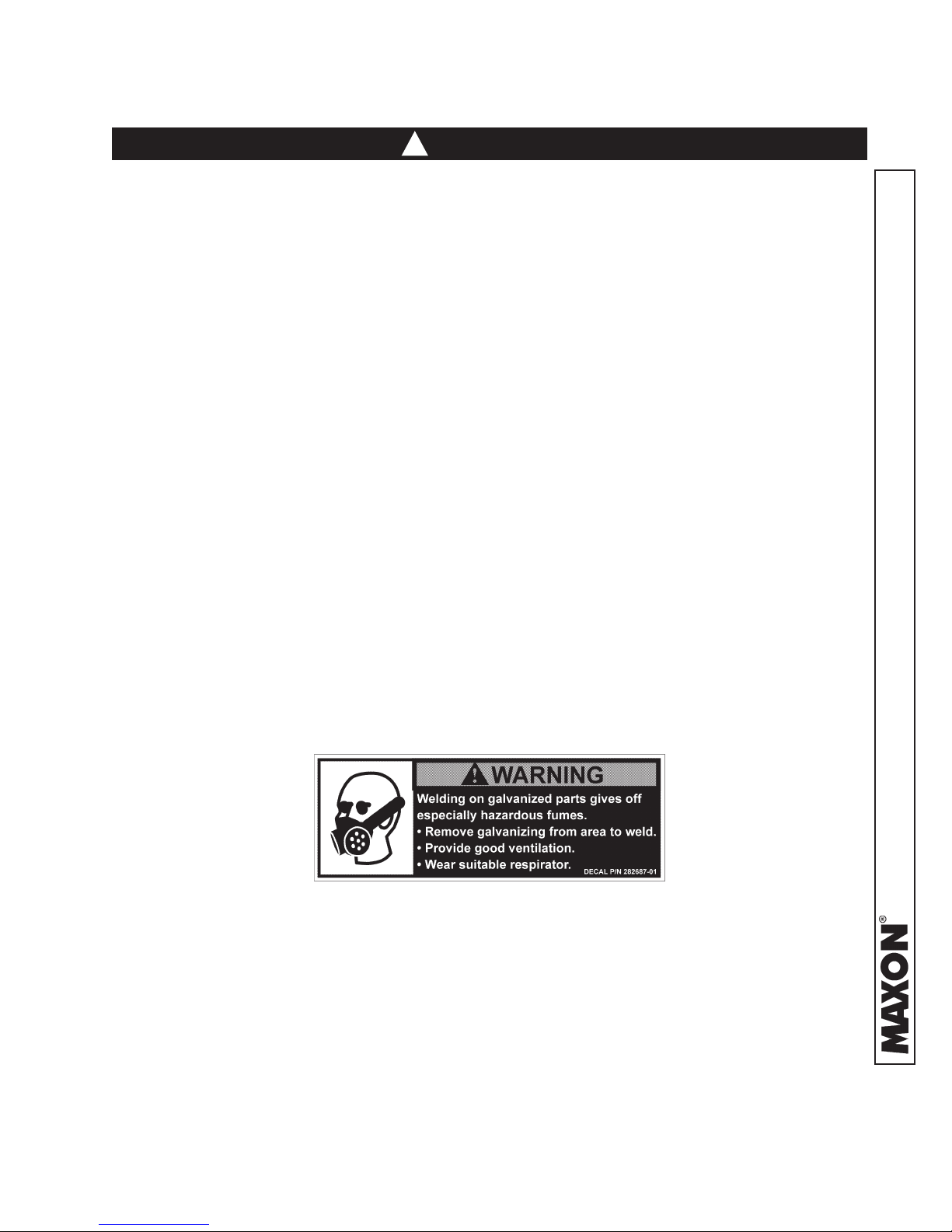
• Welding on galvanized parts gives off especially hazardous fumes. Comply with WARNING decal
on the galvanized part (
adequate ventilation, and wear suitable respirator.
FIG. 5-1). To minimize hazard remove galvanizing from weld area, provide
FIG. 5-1
11921 Slauson Ave. Santa Fe Springs, CA. 90670 (800) 227-4116 FAX (888) 771-7713
5
Page 6

SAFETY INSTRUCTIONS
• Read and understand the instructions in this Installation Manual before installing Liftgate.
• Before operating the Liftgate, read and understand the operating instructions in Operation
Manual.
• Comply with all WARNING and instruction decals attached to the Liftgate.
• Keep decals clean and legible. If decals are illegible or missing, replace them. Free replacement
decals are available from Maxon Customer Service.
• Consider the safety and location of bystanders and location of nearby objects when operating the
Liftgate. Stand to one side of the platform while operating the Liftgate.
• Do not allow untrained persons to operate the Liftgate.
• Wear appropriate safety equipment such as protective eyeglasses, faceshield and clothing while
performing maintenance on the Liftgate and handling the battery. Debris from drilling and contact
with battery acid may injure unprotected eyes and skin.
• Be careful working by an automotive type battery. Make sure the work area is well ventilated and
there are no ames or sparks near the battery. Never lay objects on the battery that can short the
terminals together. If battery acid gets in your eyes, immediately seek rst aid. If acid gets on your
skin, immediately wash it off with soap and water.
• If an emergency situation arises (vehicle or Liftgate) while operating the Liftgate, release the control switch to stop the Liftgate.
SAFETY INSTRUCTIONS
• A correctly installed Liftgate operates smoothly and reasonably quiet. The only noticeable noise
during operation comes from the power unit while the platform is raised and lowered. Listen for
scraping, grating and binding noises and correct the problem before continuing to operate Liftgate.
NOTICE
NOTICE
• Maxon Lift is responsible for the instructions to correctly install MAXON Liftgates on
trucks or trailers only.
• Liftgate installers, not Maxon Lift, are responsible for reviewing and complying with all
applicable Federal, State, and Local regulations pertaining to the trailer or truck.
• Installers of the liftgate should ensure that all trucks and trailers are equipped with grab
handles as needed.
11921 Slauson Ave. Santa Fe Springs, CA. 90670 (800) 227-4116 FAX (888) 771-7713
6
Page 7
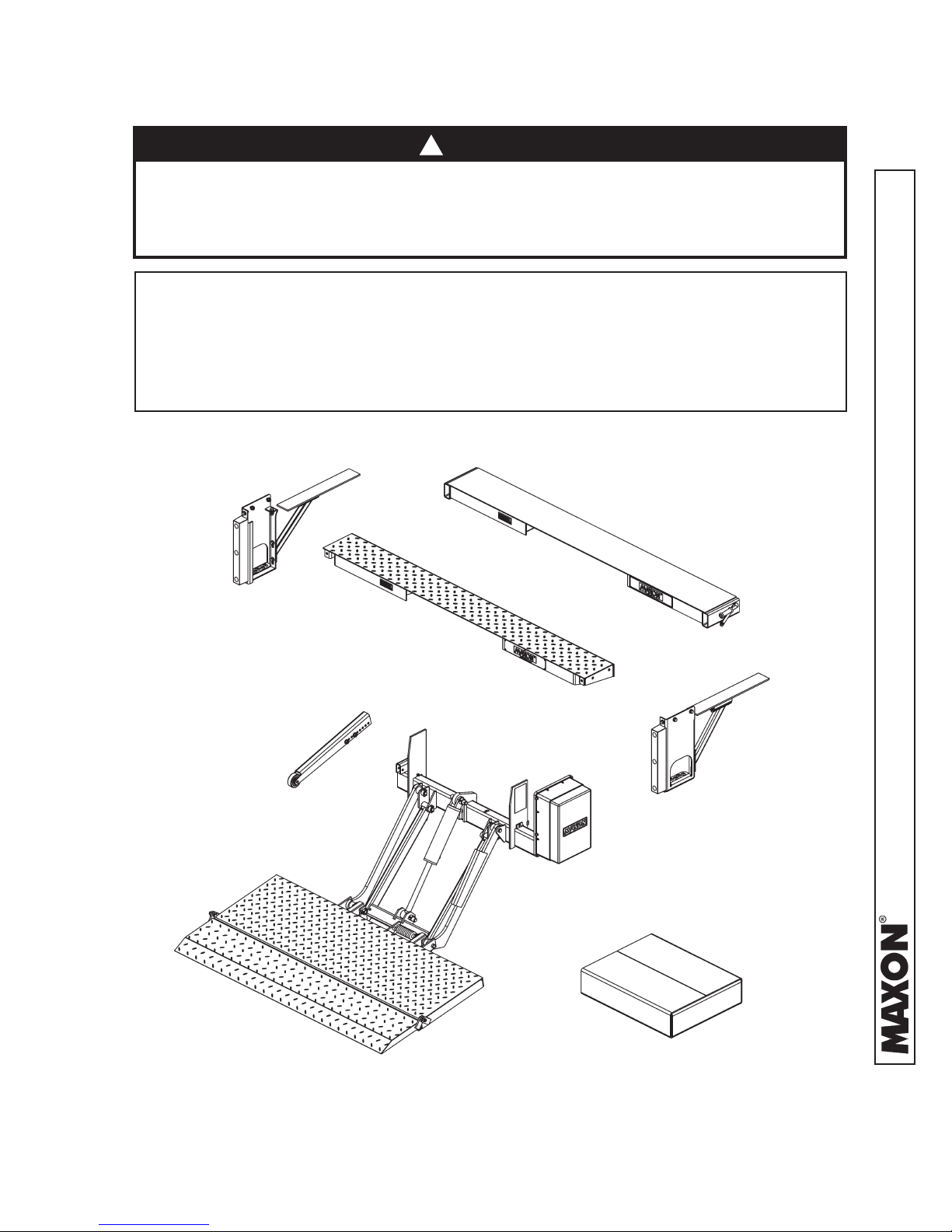
72-150 & TE-20 LIFTGATE COMPONENTS
!
CAUTION
Prevent injuries and equipment damage. Before cutting the shipping straps
from the Liftgate, put Liftgate on level ground that will support at least 1500
pounds. Be careful lifting and moving components (such as extension plate)
after shipping straps are removed.
NOTE: Make sure you have all components and parts before you start installing Lift-
gate. Compare parts in the part box and each kit box with packing list closed
in each box. If parts and components are missing or incorrect, call:
Maxon Customer Service
Call (800) 227-4116 or
Send e-mail to customersupport@maxonlift.com
WELD-ON EXTENSION PLATE
(PAINTED)
BOLT-ON STEP
(GALVANIZED
OR PAINTED)
BOLT-ON EXTENSION PLATE
(GALVANIZED OR PAINTED)
OPENER
BOLT-ON STEP
(GALVANIZED
OR PAINTED)
11921 Slauson Ave. Santa Fe Springs, CA. 90670 (800) 227-4116 FAX (888) 771-7713
PARTS BOX
72-150 & TE-20 COMPONENTS
FIG. 7-1
7
Page 8

PARTS BOX FOR 72-150 GRAVITY DOWN
(96” WIDE, PAINTED FINISH)
NOTE: To nd maintenance & parts information for your TE-20 & 72-150 Liftgate,
go to www.maxonlift.com. Click the PRODUCTS, TUK-A-WAY and TE-20
or 72-150 button. Open the Maintenance Manual in the PRODUCT DOCU-
MENTATION window.
ITEM QTY. PART NUMBER DESCRIPTION
REF 1 269661-01 PARTS BOX, 72-150 GRAVITY DOWN (PAINTED)
1 4 030458 SCREW TAPPING #10 X 1/2” LG.
2 7 050079 CLIP, FRAME
3 1 055011 RUBBER HANDLE
4 1 203417 RENTAL LOCK BRACKET, 6-1/2" LG.
5 1 203570 INNER BRACKET, 1" LG. (USE WITH RENTAL LOCK)
6 1 125674 CLAMP, JIFFY #130
7 10 205780 TIE, PLASTIC, 7" LG.
8 8 206864 TIE, PLASTIC, 12-14" LG.
9 3 214663 CLAMP, #8 RUBBER LOOM
10 1 215345 SPRING, EXTENSION, 2 1/2” LG.
11 2 251333 SHIM, 1/8" X 2" X 2" LG.
12 1 264422 CABLE ASSY, 175 AMPS, 38’ LG.
13 1 269641-01 KIT, MANUAL & DECAL 72-150
13A 1 M-12-04 MANUAL, INSTALLATION 72-150/TE-20
13B 1 M-12-05 MANUAL, OPERATION 72-150/TE-20
REFER TO DECAL
13C -
14 1 267959-01 MOLDED SWITCH ASSY
15 2 900057-5 SCREW, SELF TAPPING, #10-24 X 1” LG.
16 1 906497-02 LUG, 2GA, COPPER
PAGES IN THIS
MANUAL
DECALS
TABLE 8-1
8
11921 Slauson Ave. Santa Fe Springs, CA. 90670 (800) 227-4116 FAX (888) 771-7713
Page 9

PARTS BOX FOR 72-150 & TE-20 GRAVITY DOWN
(96” WIDE, GALVANIZED FINISH, 12 VOLT & 24 VOLT)
NOTE: To nd maintenance & parts information for your TE-20 & 72-150 Liftgate,
go to www.maxonlift.com. Click the PRODUCTS, TUK-A-WAY and TE-20
or 72-150 button. Open the Maintenance Manual in the PRODUCT DOCU-
MENTATION window.
ITEM QTY. PART NUMBER DESCRIPTION
REF 1
1 4 030458 SCREW TAPPING #10 X 1/2” LG.
2 7 050079 CLIP, FRAME
3 1 125674 CLAMP, JIFFY #130
4 10 205780 TIE, PLASTIC, 7" LG.
5 2 206864 TIE, PLASTIC, 12-14" LG.
6 3 214663 CLAMP, #8 RUBBER LOOM
7 2 251333 SHIM, 1/8" X 2" X 2" LG.
8 1 264422 CABLE ASSY, 175 AMPS, 38’ LG.
9 1
9A 1 M-12-04 MANUAL, INSTALLATION 72-150/TE-20
9B 1 M-12-05 MANUAL, OPERATION 72-150/TE-20
9C -
10 1 267959-01 MOLDED SWITCH ASSY
11 2 900057-5 SCREW, SELF TAPPING, #10-24 X 1” LG.
12 1 906497-02 LUG, 2GA, COPPER
269642-01 PARTS BOX, 72-150 GRAVITY DOWN (GALVANIZED)
269642-03 PARTS BOX, TE-20 GRAVITY DOWN (GALVANIZED)
269641-01 KIT, MANUAL & DECAL 72-150
269641-02 KIT, MANUAL & DECAL TE-20
REFER TO DECAL
PAGES IN THIS
MANUAL
DECALS
11921 Slauson Ave. Santa Fe Springs, CA. 90670 (800) 227-4116 FAX (888) 771-7713
TABLE 9-1
9
Page 10

PARTS BOX FOR 72-150 POWER DOWN
(96” WIDE, PAINTED FINISH)
NOTE: To nd maintenance & parts information for your TE-20 & 72-150 Liftgate,
go to www.maxonlift.com. Click the PRODUCTS, TUK-A-WAY and TE-20
or 72-150 button. Open the Maintenance Manual in the PRODUCT DOCU-
MENTATION window.
ITEM QTY. PART NUMBER DESCRIPTION
REF 1 269661-03 PARTS BOX, 72-150 GRAVITY DOWN (PAINTED)
1 4 030458 SCREW TAPPING #10 X 1/2” LG.
2 7 050079 CLIP, FRAME
3 1 055011 RUBBER HANDLE
4 1 203417 RENTAL LOCK BRACKET, 6-1/2" LG.
5 1 203570 INNER BRACKET, 1" LG. (USE WITH RENTAL LOCK)
6 1 125674 CLAMP, JIFFY #130
7 10 205780 TIE, PLASTIC, 7" LG.
8 8 206864 TIE, PLASTIC, 12-14" LG.
9 3 214663 CLAMP, #8 RUBBER LOOM
10 1 215345 SPRING, EXTENSION, 2 1/2” LG.
11 2 251333 SHIM, 1/8" X 2" X 2" LG.
12 1 264422 CABLE ASSY, 175 AMPS, 38’ LG.
13 1 269641-01 KIT, MANUAL & DECAL 72-150
13A 1 M-12-04 MANUAL, INSTALLATION 72-150/TE-20
13B 1 M-12-05 MANUAL, OPERATION 72-150/TE-20
REFER TO DECAL
13C -
14 1 264951-04 MOLDED SWITCH & CABLE ASSEMBLY
15 2 900057-5 SCREW, SELF TAPPING, #10-24 X 1” LG.
16 1 906497-02 LUG, 2GA, COPPER
PAGES IN THIS
MANUAL
DECALS
TABLE 10-1
10
11921 Slauson Ave. Santa Fe Springs, CA. 90670 (800) 227-4116 FAX (888) 771-7713
Page 11

PARTS BOX FOR 72-150 & TE-20 POWER DOWN
(96” WIDE, GALVANIZED FINISH)
NOTE: To nd maintenance & parts information for your TE-20 & 72-150 Liftgate,
go to www.maxonlift.com. Click the PRODUCTS, TUK-A-WAY and TE-20
or 72-150 button. Open the Maintenance Manual in the PRODUCT DOCU-
MENTATION window.
ITEM QTY. PART NUMBER DESCRIPTION
REF 1
1 4 030458 SCREW TAPPING, #10 X 1/2” LG.
2 7 050079 CLIP, FRAME
3 1 125674 CLAMP, JIFFY #130
4 10 205780 TIE, PLASTIC, 7" LG.
5 2 206864 TIE, PLASTIC, 12-14" LG.
6 3 214663 CLAMP, #8 RUBBER LOOM
7 2 251333 SHIM, 1/8" X 2" X 2" LG.
8 1 264422 CABLE ASSY, 175 AMPS, 38’ LG.
9 1
9A 1 M-12-04 MANUAL, INSTALLATION 72-150/TE-20
9B 1 M-12-05 MANUAL, OPERATION 72-150/TE-20
9C -
10 1 264951-04 MOLDED SWITCH & CABLE ASSEMBLY
11 1 202406 BRASS ELBOW 1/4” X 1/4”
12 2 900057-5 SCREW, SELF TAPPING, #10-24 X 1” LG.
13 1 906497-02 LUG, 2GA, COPPER
269642-02 PARTS BOX, TE-20 POWER DOWN (GALVANIZED)
269642-04 PARTS BOX, 72-150 POWER DOWN (GALVANIZED)
269641-01 KIT, MANUAL & DECAL, 72-150
269641-02 KIT, MANUAL & DECAL, TE-20
REFER TO DECAL
PAGES IN THIS
MANUAL
DECALS
TABLE 11-1
11921 Slauson Ave. Santa Fe Springs, CA. 90670 (800) 227-4116 FAX (888) 771-7713
11
Page 12
VEHICLE REQUIREMENTS
NOTE: The maximum (unloaded) operating vehicle body bed height for the 72-150
& TE-20 Liftgates equipped with wedge ipover or ramp ipover is 54”.
The minimum height for the 72-150 & TE-20 Liftgates equipped with
wedge ipover is 44” (loaded). The minimum height for 72-150 and TE20 Liftgates equipped with ramp ipover is 38” (loaded). Do not install
this Liftgate on vehicle bodies equipped with swing open doors.
NOTE: Make sure vehicle is parked on level ground while preparing vehicle and
installing Liftgate.
NOTE: Dimensions are provided as a reference only for tting Liftgate to vehicle
body.
NOTE: Measure the width of the Liftgate and the width of the vehicle body before
you start doing this procedure. Ensure the Liftgate is the correct width for
vehicle.
The vehicle clearance dimensions and vehicle chassis cutout dimensions, for
72-150 and TE-20 Liftgates, are shown on the pages that follow. Dimensions
are given for high bed and low bed installations.
11921 Slauson Ave. Santa Fe Springs, CA. 90670 (800) 227-4116 FAX (888) 771-7713
12
Page 13
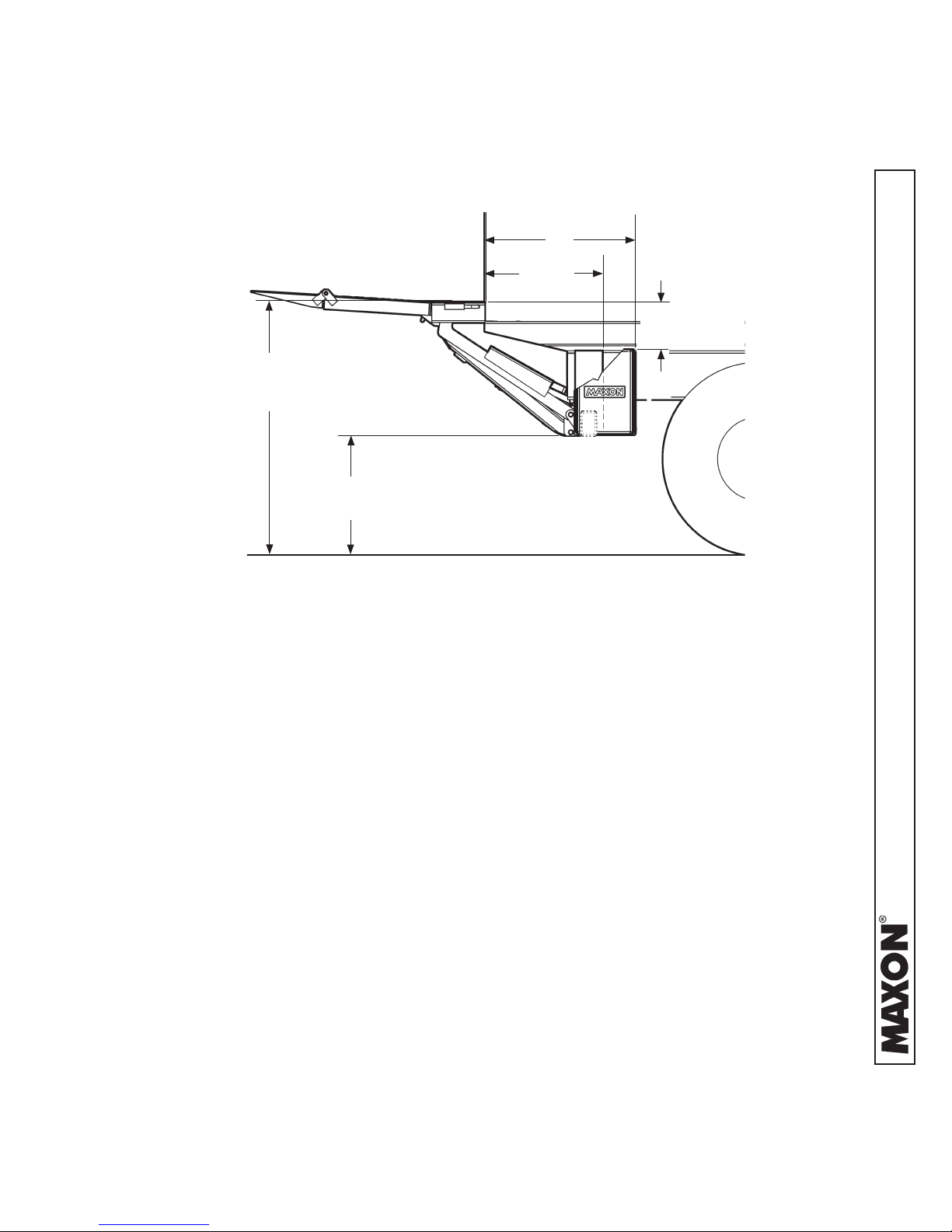
VEHICLE REQUIREMENTS - Continued
PLATFORM WITH WEDGE FLIPOVER
29”
22-1/2”
11 9/16”
54” MAX. (UNLOADED)
44” MIN. (LOADED)
24-1/2” MAX.
14-3/4” MIN.
CLEARANCES FOR TE-20 & 72-150, HIGH BED HEIGHT ONLY
FIG. 13-1
11921 Slauson Ave. Santa Fe Springs, CA. 90670 (800) 227-4116 FAX (888) 771-7713
13
Page 14

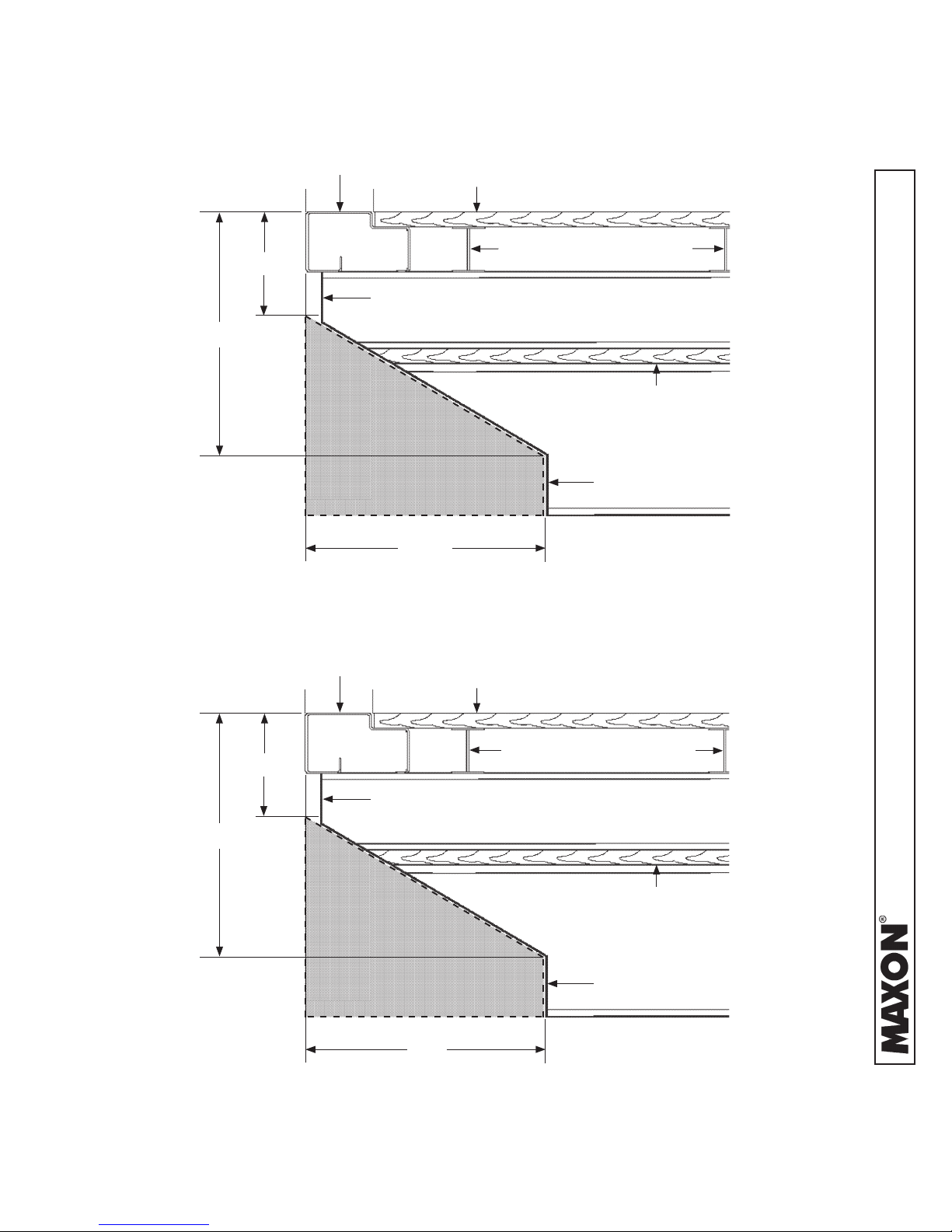
VEHICLE REQUIREMENTS - Continued
PLATFORM WITH RAMP FLIPOVER
29”
22-1/2”
11
54” MAX. (UNLOADED)
42” MIN. (LOADED)
24-1/8” MAX.
12-1/8” MIN.
CLEARANCES FOR TE-20 & 72-150 ON HIGH BED HEIGHT
FIG. 14-1
32”
24-1/4”
9-1/2
44” MAX. (UNLOADED)
38” MIN. (LOADED)
16-1/2” MAX.
10-1/2” MIN.
11921 Slauson Ave. Santa Fe Springs, CA. 90670 (800) 227-4116 FAX (888) 771-7713
CLEARANCES FOR TE-20 & 72-150 ON LOW BED HEIGHT
FIG. 14-2
14
Page 15
VEHICLE REQUIREMENTS - Continued
REAR SILL
6”
BODY FRAME
10”
PLATFORM CLEARANCE
CUTOUT AREA
(WITHIN DASHED LINES)
BODY FLOOR
BODY CROSS MEMBERS
SPACER
TRUCK FRAME
17”
VEHICLE FRAME CUT FOR TE-20 & 72-150 (44” TO 54” BED HEIGHTS)
FIG. 15-1
REAR SILL
5-1/2”
BODY FRAME
9”
PLATFORM CLEARANCE
CUTOUT AREA
(WITHIN DASHED LINES)
BODY FLOOR
BODY CROSS MEMBERS
SPACER
TRUCK FRAME
17”
VEHICLE FRAME CUT FOR TE-20 & 72-150 (38” TO 46” BED HEIGHTS)
FIG. 15-2
11921 Slauson Ave. Santa Fe Springs, CA. 90670 (800) 227-4116 FAX (888) 771-7713
15
Page 16

STEP 1 - INSTALL EXTENSION PLATES
NOTE: TE-20 Liftgates may be equipped with two types of extensions plates. The
painted extension plate (FIG. 16-1) does not have bolt holes and is welded
on. Weld-on support straps and spacers (ats), provided with parts bags,
must be used. The galvanized extension plate (FIG. 16-2) has bolt holes
so it can be bolted to vehicle body. GRADE 8 bolts are required. MAXON
recommends getting the optional extension plate hardware kit listed in OP-
TIONS section. It also has holes for bolt-on installation brackets, provided
with parts bags. Refer to the following instructions for installing painted
extension plates or galvanized extension plates.
PAINTED WELD-ON EXTENSION PLATE
FIG. 16-1
GALVANIZED BOLT-ON EXTENSION PLATE
FIG. 16-2
11921 Slauson Ave. Santa Fe Springs, CA. 90670 (800) 227-4116 FAX (888) 771-7713
16
Page 17
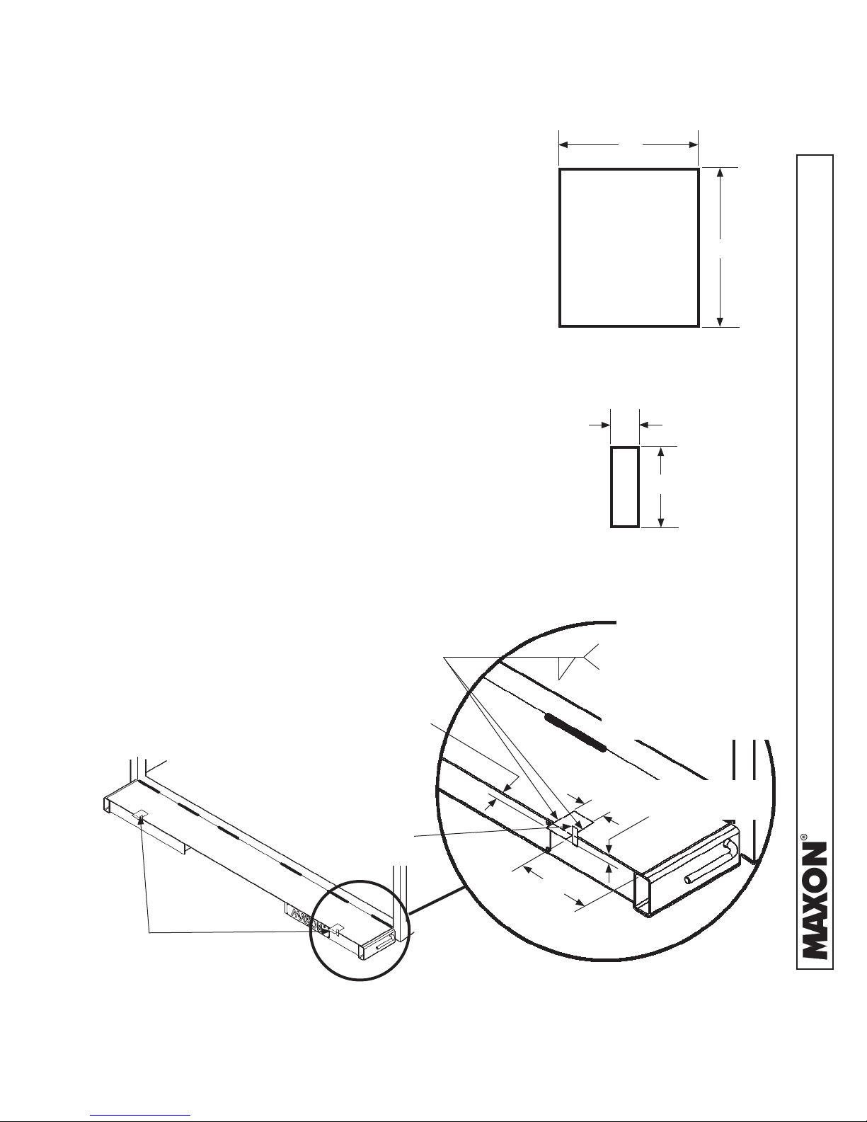
STEP 1 - INSTALL EXTENSION PLATES - Continued
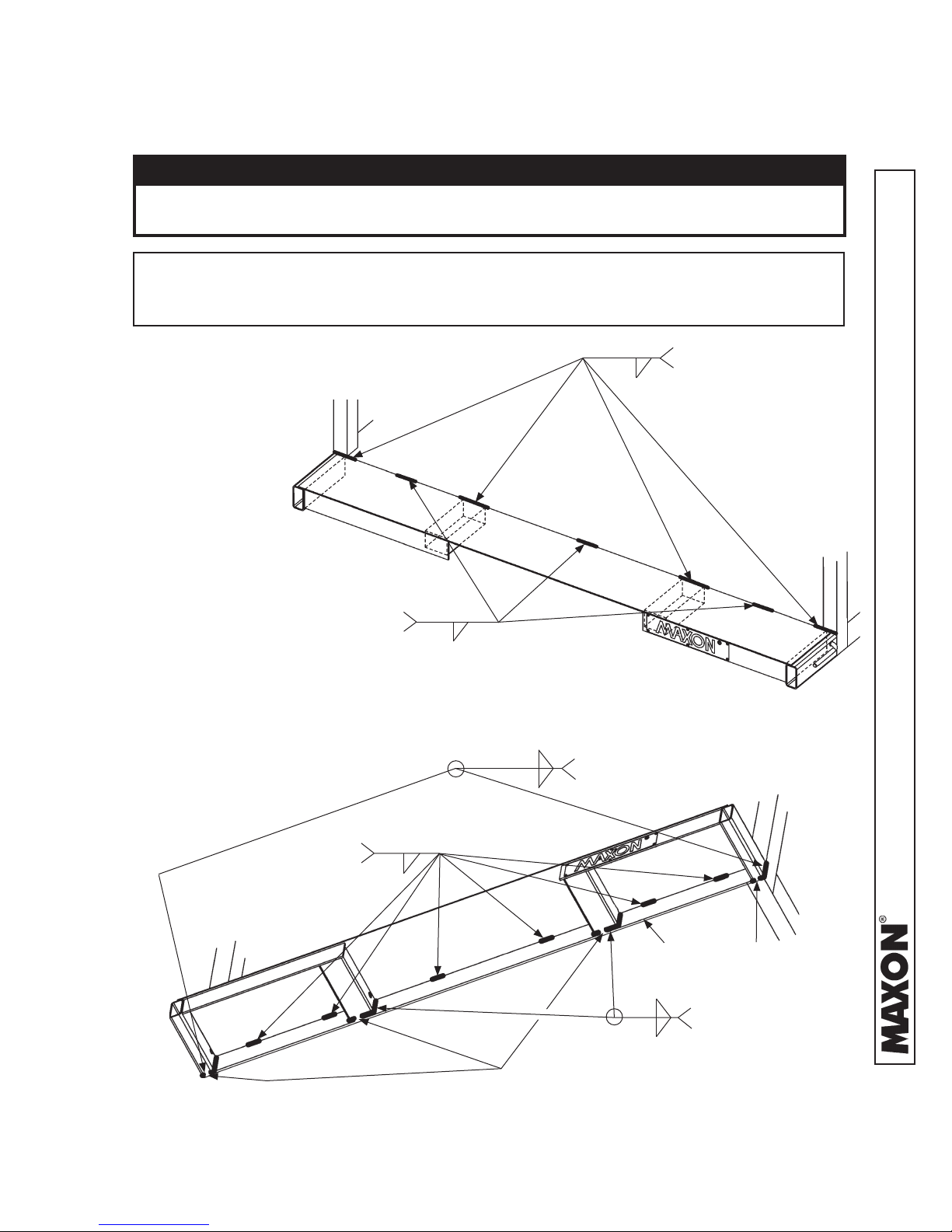
WELD PAINTED EXTENSION PLATE TO VEHICLE
CAUTION
To protect the original paint system, a 3” wide area of paint must be removed
from all sides of the weld area before welding.
NOTE: Before welding extension plate to vehicle body, make sure:
• Inboard edge of extension plate is ush with the top of sill on vehicle body.
• Top surface of extension plate is level with the ground.
1. Center the extension
plate on vehicle body.
Weld the extension
plate to vehicle body
sill as shown in FIGS.
17-1 and 17-2
EQUALLY SPACED
BETWEEN 4” LG WELDS
EXTENSION PLATE WELDS - VIEWED FROM ABOVE
2” LG (TYP.)
1/4”
FIG. 17-1
1/4”
1/4”
1/4”
2 PLACES, MAKE 1” GAP
WHERE SHOWN
5” LG (TYP.), 4 PLACES
CENTER OVER WIDTH
OF 2 CHANNELS AND 2
TUBES (UNDER FLOORPLATE - SEE DASHED
LINES)
2” LG, 6 PLACES
EQUAL SPACING
(TYP.)
EXTENSION PLATE WELDS - VIEWED FROM UNDERNEATH
1/4”
1” GAP
FIG. 17-2
17
SILL
(PART OF
VEHICLE BODY)
1/4”
1/4”
1” GAP
2 PLACES, MAKE 1”
GAP WHERE SHOWN
11921 Slauson Ave. Santa Fe Springs, CA. 90670 (800) 227-4116 FAX (888) 771-7713
Page 18
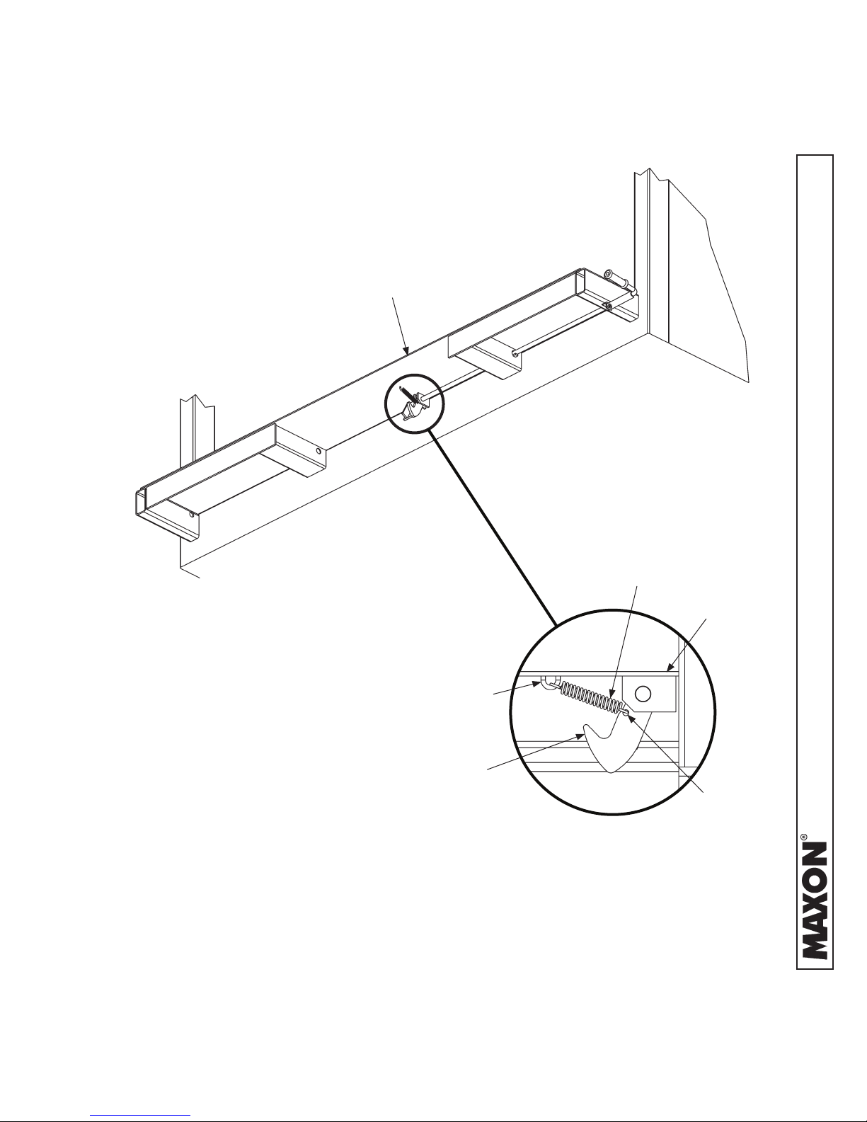
STEP 1 - INSTALL EXTENSION PLATES - Continued
2. Get extension spring (FIG. 18-1A) from
parts box. Hook one end of spring in loop
(FIG. 18-1A) under extension plate (FIG.
18-1). Next, hook opposite end of spring
in eye of the safety hook (FIG. 18-1A).
EXTENSION PLATE
EXTENSION SPRING PLACEMENT
FIG. 18-1
LOOP
SAFETY
HOOK
EXTENSION
SPRING
EXTENSION
PLATE
EYE
11921 Slauson Ave. Santa Fe Springs, CA. 90670 (800) 227-4116 FAX (888) 771-7713
HOOKING EXTENSION SPRING
RH SIDE VIEW
FIG. 18-1A
18
Page 19
STEP 1 - INSTALL EXTENSION PLATES - Continued
3. Make 2 support straps (FIG. 19-1) and
2 spacers (FIG. 19-2) to keep Liftgate in
proper position. While welding Liftgate to
vehicle, support straps keep platform level
with extension plate and spacers keep 1/4”
between platform and extension plate.
4. Place 2 temporary support straps (FIG. 19-3A)
on the extension plate as shown in FIG. 19-3A.
Also, put 2 temporary spacers (FIG. 19-3B) between platform and extension plate as shown
in FIG. 19-3B. Weld the straps and spacers to
extension plate (FIG. 19-3B).
4”
5”
SUPPORT STRAP
(3/8” X 4” STEEL FLAT)
FIG. 19-1
1”
2-1/2”
SPACER
(1/4” X 1” STEEL FLAT)
FIG. 19-2
SUPPORT
STRAPS
1” (APPROX. - TYP.
STRAP OVERHANG)
FIG. 19-3A
1/4” SPACER
1/4” LG. TACK,
SUPPORT
STRAP TO EXTENSION
1/4”
14”
PLATE (1 WELD ONLY),
SPACER & SUPPORT
STRAP TO EXTENSION
PLATE (1 WELD ONLY)
1/2” (APPROX. - TYP.
SPACER OVERHANG)
4”
STRAP & SPACER WELDS
(TYPICAL - STRAP & SPACER AT BOTH
ENDS OF EXTENSION PLATE)
FIG. 19-3B
11921 Slauson Ave. Santa Fe Springs, CA. 90670 (800) 227-4116 FAX (888) 771-7713
19
Page 20
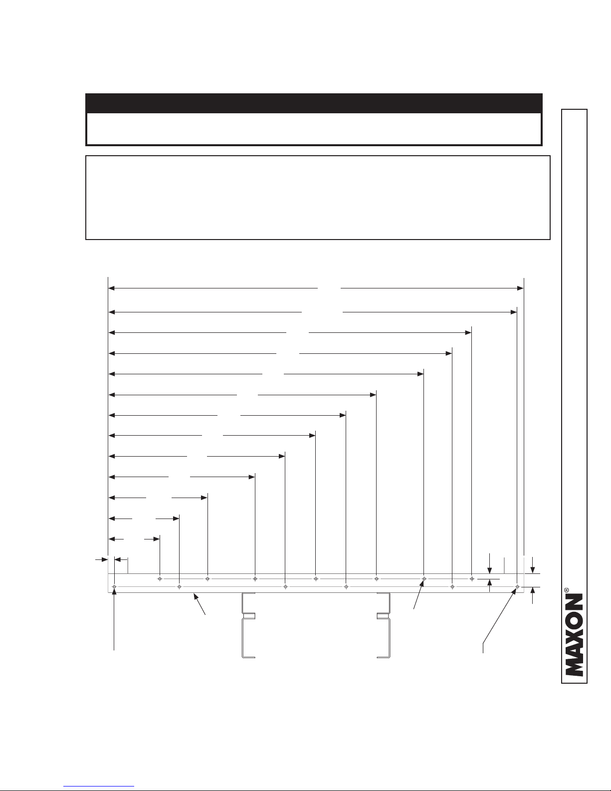
STEP 1 - INSTALL EXTENSION PLATES - Continued
BOLT GALVANIZED EXTENSION PLATE TO VEHICLE
CAUTION
To preserve the corrosion resistance properties of the galvanized nish,
MAXON recommends bolting the galvanized extension plate to vehicle.
NOTE: The extension plate has bolt holes so it can be bolted to vehicle body. Grade
8 bolts are required. MAXON recommends getting the optional extension
plate hardware kit listed in OPTIONS section. Vehicle body must be drilled
according to instructions. If necessary, extension plate may also be welded to
vehicle body. Do the following bolting or welding instructions.
1. Mark and drill holes into rear sill as shown in FIG. 20-1.
96”
94-1/2”
82”
19”
14”
1-1/2”
24”
34”
41”
REAR
SILL
48”
55”
62”
72”
77”
USE 19/32” DRILL
(13 PLACES)
1-1/4”
11921 Slauson Ave. Santa Fe Springs, CA. 90670 (800) 227-4116 FAX (888) 771-7713
3-1/8”
HOLE ONLY REQUIRED
WHEN BOLTING
THROUGH CORNER POST.
REAR SILL - HOLE LOCATIONS FOR 96” WIDE VEHICLE
HOLE ONLY REQUIRED
WHEN BOLTING
THROUGH CORNER POST.
FIG. 20-1
20
Page 21
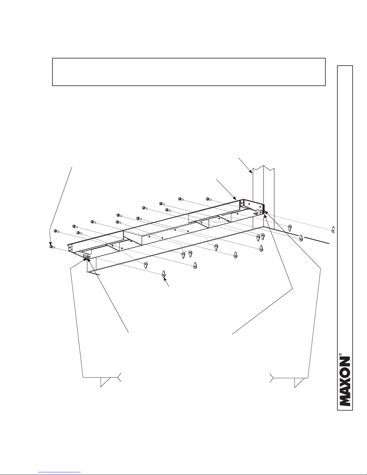
STEP 1 - INSTALL EXTENSION PLATES - Continued
NOTE: Do not tighten extension plate bolts and lock nuts until:
• All the bolts and lock nuts are in place.
• Top of extension plate is ush with top of rear sill.
2. Bolt extension plate to vehicle as shown in FIG. 21-1. If necessary, reposition
extension plate so top surface is ush with top surface of sill. Then, torque bolts
and lock nuts to 105 lb.-ft.
FRAME BOLT, HEX
1/2”-13 X 1 3/4” LG, GR8
(13 PLACES)
VEHICLE
BODY
EXTENSION
PLATE
TEAR DROP NUT 1/2”-13
(13 PLACES 96” EXTENSION PLATE,
15 PLACES 102” EXTENSION PLATE)
3/16”
WELD VERT. EDGE
IF NOT BOLTING
BOLTING EXTENSION PLATE (96” WIDE EXTENSION PLATE SHOWN)
IF NO CORNER POST ACCESS FOR
BOLT & NUT, WELD OUTSIDE EDGES
AS SHOWN.
WELD VERT. EDGE
IF NOT BOLTING
FIG. 21-1
21
11921 Slauson Ave. Santa Fe Springs, CA. 90670 (800) 227-4116 FAX (888) 771-7713
3/16”
Page 22

STEP 1 - INSTALL EXTENSION PLATES - Continued
WELD GALVANIZED EXTENSION PLATE TO VEHICLE
`
WARNING
!
Welding on galvanized parts gives off especially hazardous fumes. To mini-
mize hazard remove galvanizing from weld area, provide adequate ventilation,
and wear suitable respirator.
CAUTION
To preserve the corrosion resistance properties of the galvanized nish,
MAXON recommends bolting the galvanized extension plate to vehicle.
Center the extension plate on vehicle body. Before welding extension plate to vehicle
body, make sure top surface of extension plate is ush with oor of vehicle body.
Weld the extension plate to vehicle body sill as shown in FIGS. 22-1 and 22-2.
3/16”
3/16”
WELD LENGTH &
SPACE: 2” - 11 3/4”
EXTENSION
PLATE
VEHICLE
BODY
EXTENSION PLATE WELDS - VIEWED FROM ABOVE
FIG. 22-1
EXTENSION
PLATE
VEHICLE
BODY
3/16”
WELD LENGTH &
SPACE: 2” - 11 3/4”
3/16”
11921 Slauson Ave. Santa Fe Springs, CA. 90670 (800) 227-4116 FAX (888) 771-7713
EXTENSION PLATE WELDS - VIEWED FROM UNDERNEATH
FIG. 22-2
22
Page 23

STEP 1 - INSTALL EXTENSION PLATES - Continued
WELD INSTALLATION BRACKETS
`
!
WARNING
Welding on galvanized parts gives off
especially hazardous fumes. To minimize hazard remove galvanizing from
weld area, provide adequate ventilation, and wear suitable respirator.
1. Make 2 support straps (FIG. 23-1) and
2 spacers (FIG. 23-2) to keep Liftgate in
proper position. While welding Liftgate to
vehicle, support straps keep platform level
with extension plate and spacers keep 1/4”
between platform and extension plate.
2. Place 2 temporary support straps (FIG. 23-3)
on the extension plate as shown in FIG. 23-3.
Also, put 2 temporary spacers (FIG. 23-3) between platform and extension plate as shown
in FIG. 23-3. Weld the straps and spacers to
extension plate (FIG. 23-3).
SUPPORT STRAP
(3/8” X 4” STEEL FLAT)
(1/4” X 1” STEEL FLAT)
4”
FIG. 23-1
1”
SPACER
FIG. 23-2
5”
2-1/2”
SUPPORT
STRAPS
1/4” LG. TACK, SUPPORT STRAP TO
1/4”
1” (APPROX. - TYP.
STRAP OVERHANG)
14”
EXTENSION PLATE (1 WELD ONLY),
SPACER & SUPPORT STRAP TO
EXTENSION PLATE (1 WELD ONLY)
1/4” SPACER
4”
BOLTING ON INSTALLATION BRACKETS
FIG. 23-3
11921 Slauson Ave. Santa Fe Springs, CA. 90670 (800) 227-4116 FAX (888) 771-7713
1/2”
(APPROX. - TYP.
SPACER OVERHANG)
23
Page 24

STEP 2 - WELD LIFTGATE TO VEHICLE
WARNING
!
Do not remove lock angle until instructed to do so in this manual.
1. Unfold the platform as shown
in FIGS. 24-1 and 24-2.
NOTE: Liftgates are shipped with
the locking angle set up for
low bed. Check your locking angle dimension (FIGS.
24-1 & 24-2) before installing
Liftgate. If locking angle is not
in correct position for your bed
height, remove and reposition
locking angle (FIGS. 24-1 &
24-2).
FLIPOVER (LOW BED, 38”- 46” HEIGHT)
LOCKING
ANGLE
UNFOLDED PLATFORM WITH RAMP
FIG. 24-1
23-1/4”
!
WARNING
Support Liftgate before removing
locking angle. To prevent possible
injury, never work in the area under
the platform.
22-3/4”
11921 Slauson Ave. Santa Fe Springs, CA. 90670 (800) 227-4116 FAX (888) 771-7713
LOCKING ANGLE
UNFOLDED PLATFORM WITH RAMP OR
WEDGE FLIPOVER, RAMP IS SHOWN
(HIGH BED, 44”- 54” HEIGHT)
FIG. 24-2
24
Page 25

STEP 2 - WELD LIFTGATE TO VEHICLE - Continued
!
WARNING
To prevent injury, support Liftgate to keep it from tipping over. Stay clear of
place under the platform where Liftgate could fall on you.
CAUTION
To protect the original paint system if equipped, a 3” wide area of paint must
be removed from all sides of the weld area before welding.
NOTE: To prevent misalignment when hoisting Liftgate by the platform, each plat-
form stop must be tack welded to shackle.
2. Tack weld platform stops to shackles,
on LH and RH side of platform, as
shown in FIGS. 25-1A and 25-1B.
PLATFORM
PLATFORM
STOP
SHACKLE
3/16”
TACK WELDING
PLATFORM STOPS
FIG. 25-1B
3. Attach chain and hoist on each side of
platform at positions shown in FIG. 25-2.
(Place chain all around platform.) Hoist
the Liftgate, and then place oor jack
under main frame (FIG. 25-2). Jack the
Liftgate into position. Make sure vehicle
oor is horizontal and pins are lined up
as shown in FIG. 25-2.
FLOOR JACK
TACK
FIG. 25-1A
HOIST HERE
PINS
VERTICAL
VEHICLE FLOOR
(HORIZONTAL)
11921 Slauson Ave. Santa Fe Springs, CA. 90670 (800) 227-4116 FAX (888) 771-7713
MAIN
FRAME
FIG. 25-2
25
Page 26

STEP 2 - WELD LIFTGATE TO VEHICLE - Continued
!
WARNING
Painted Liftgate is shipped from factory with mounting plates that are only tack
welded to main frame. Weld as shown in illustration before operating Liftgate.
NOTE: The mounting plates on the galvanized main frame are fully welded at the
factory, and are suitable for vehicle with 33-3/4” frame width. Do not move
the galvanized mounting plates. The following instruction only applies to
painted mounting plates.
4. Unbolt mounting plate
from main frame. Reposition the mounting plate
against vehicle frame.
Tack weld as shown in
FIG. 26-1. Repeat for
second mounting plate
(reposition and tack
weld).
VEHICLE FRAME
(TYPICAL TRUCK
FRAME SHOWN)
UNBOLT TO REPOSITION
MOUNTING PLATE)
MOUNTING
PLATE
NOTE: Weld both mounting plates to
vehicle frame before welding
mounting plates to main frame.
5. Clamp both mounting
plates to vehicle frame.
Weld the mounting plates
to vehicle frame as shown
in FIG. 26-2. Remove
clamps.
2” LG. 4 PLACES
(TYPICAL - RH & LH
TACK
(TYPICAL - RH & LH
MOUNTING PLATES)
MAIN FRAME
(CUT-AWAY VIEW)
REPOSITIONING MOUNTING PLATE
VEHICLE FRAME
(TYPICAL TRUCK
FRAME SHOWN)
MOUNTING
PLATES)
1/4”
(RH SIDE SHOWN)
FIG. 26-1
11921 Slauson Ave. Santa Fe Springs, CA. 90670 (800) 227-4116 FAX (888) 771-7713
1/4”
MOUNTING
PLATE
WELD TO VEHICLE FRAME AND MAIN FRAME
(RH SIDE SHOWN)
FIG. 26-2
26
Page 27

STEP 3 - ATTACH OPTIONAL BATTERY BOX & FRAME
TO VEHICLE (IF EQUIPPED)
RECOMMENDED CONFIGURATION
NOTE: Make sure the Liftgate power unit, and all batteries on the vehicle for the
power unit, are connected correctly to a common chassis ground.
1. Liftgate and optional
battery box are typically
installed on trailers as
shown in FIG. 27-1 and
on trucks as shown in
FIG. 27-2. See the following page for battery
and cable connections.
LIFTGATE
LIFTGATE
POWER UNIT
FUSED CABLE
OPTIONAL
BATTERY BOX,
TYPICAL LOCATION
TRACTOR BATTERIES,
TYPICAL LOCATION
175 AMP
FUSED CABLE
175 AMP
CIRCUIT
BREAKER
RECOMMENDED LIFTGATE & OPTIONAL BATTERY BOX
INSTALLATION ON TRAILER
FIG. 27-1
TRUCK BATTERIES,
TYPICAL LOCATION
175 AMP
FUSED CABLE
175 AMP
FUSED CABLE
LIFTGATE
LIFTGATE
POWER UNIT
OPTIONAL
BATTERY BOX,
TYPICAL LOCATION
CIRCUIT
BREAKER
11921 Slauson Ave. Santa Fe Springs, CA. 90670 (800) 227-4116 FAX (888) 771-7713
RECOMMENDED LIFTGATE & BATTERY BOX
INSTALLATION ON TRUCK
FIG. 27-2
27
Page 28

STEP 3 - ATTACH OPTIONAL BATTERY BOX & FRAME
TO VEHICLE (IF EQUIPPED) - Continued
2. Select holes on top of battery box
frame to align mounting brackets
ush to cross members. Refer
to FIGS. 28-1A & 28-1B for trailers and FIG. 28-2 for trucks. Bolt
mounting brackets to battery box
frame as shown in FIG. 28-1C.
Torque each bolt and lock nut to
85-128 lb-ft.
TRAILER BODY
CROSS MEMBER
MOUNTING
BRACKETS
BATTERY BOX
FRAME
LOCK NUT
WASHER
MOUNTING
BRACKETS
LOCK
WASHER
CROSS
MEMBER
WASHER
CAP SCREW
BOLTING BRACKETS
(8 PLACES)
FIG. 28-1C
BATTERY BOX
FRAME
FLUSH BRACKETS
FOR TRAILERS
(8 PLACES)
FIG. 28-1B
TRUCK BODY
CROSS MEMBER
MOUNTING
BRACKETS
FLUSH BRACKETS FOR TRUCKS
ALIGNING BATTERY
BOX FRAME
(TRAILER SHOWN)
FIG. 28-1A
BATTERY BOX
FRAME
(8 PLACES)
FIG. 28-2
11921 Slauson Ave. Santa Fe Springs, CA. 90670 (800) 227-4116 FAX (888) 771-7713
28
Page 29

STEP 3 - ATTACH OPTIONAL BATTERY BOX & FRAME
TO VEHICLE (IF EQUIPPED) - Continued
NOTE: If welding mounting brackets to cross members, skip instruction 3.
3. Using mounting brackets as a tem-
plate mark and drill holes through
cross members (FIG. 29-1). Bolt
mounting brackets to cross members as shown in FIGS. 29-2A and
29-2B. Torque bolts and lock nuts
to 85-128 lb-ft.
MOUNTING
BRACKETS
1/2” HOLES
MARK AND DRILL
FIG. 29-1
WASHERS
(4 PLACES)
CROSS
MEMBER
LOCK NUTS
(2 PLACES)
CAP SCREWS
(2 PLACES)
CROSS
MEMBERS
LOCK WASHERS
(2 PLACES)
MOUNTING
BRACKETS
CROSS
MEMBER
BOLTING BRACKETS
(8 PLACES)
FIG. 29-2B
11921 Slauson Ave. Santa Fe Springs, CA. 90670 (800) 227-4116 FAX (888) 771-7713
BOLTING BATTERY BOX FRAME
FIG. 29-2A
29
Page 30

STEP 3 - ATTACH OPTIONAL BATTERY BOX & FRAME
TO VEHICLE (IF EQUIPPED) - Continued
!
WARNING
Recommended practices for welding on steel parts are contained in the cur-
rent AWS (American Welding Society) D1.1 Structural Welding Code - Steel.
Damage to Liftgate and/or vehicle, and personal injury can result from welds
that are done incorrectly.
CAUTION
To prevent pump box components from being damaged by electric current
from welding, connect welder grounding cable to the part being welded.
CAUTION
Cover pump box and optional battery box with ame-resistant covering before
welding pump box frame to vehicle.
4. For galvanized frame, read
warning decal shown in FIGS.
30-1A and FIGS. 30-1B before
welding. Weld each bracket to
cross members as shown in
FIGS. 30-1A and 30-1C. Weld
top of bracket if accessible.
MEMBERS
CROSS
IF ACCESSIBLE
3/16”
WELDING BRACKETS
3/16”
(8 PLACES)
FIG. 30-1C
CROSS
MEMBERS
3/16”
BRACKET
11921 Slauson Ave. Santa Fe Springs, CA. 90670 (800) 227-4116 FAX (888) 771-7713
WELDING GALVANIZED, WARNING DECAL
FIG. 30-1B
BOLTING PUMP & BATTERY
BOX FRAME
FIG. 30-1A
30
Page 31

STEP 3 - ATTACH OPTIONAL BATTERY BOX & FRAME
TO VEHICLE (IF EQUIPPED) - Continued
!
WARNING
Remove all rings, watches and jewelry before doing any electrical work.
NOTE: Always connect fused end of power cable to battery positive (+) terminal.
NOTE: To connect charge lines, refer to instructions provided with each charge
line kit.
NOTE: MAXON recommends using dielectric grease on all electrical connections.
5. Connect battery cables, fused cables, and ground
cables for 12 volt power as shown in FIG. 31-1 or
24 volt power as shown in FIG. 32-1.
GROUND CABLE TO PUMP
BOX OR COMMON CHASSIS
GROUND, 74” LG.
(BATTERY BOX KIT ITEM)
FUSED CABLE TO PUMP BOX
(IN PARTS BOX)
10” LG.
BLACK CABLE
10” LG.
RED CABLE
(-) BATTERY
CABLE TO
COMMON
GROUND
FUSED CABLE
(SEE NOTE)
150 AMP
CIRCUIT
BREAKER
11921 Slauson Ave. Santa Fe Springs, CA. 90670 (800) 227-4116 FAX (888) 771-7713
12” LG.
RED CABLE
12 VOLT BATTERY CONNECTIONS
FOR 12 VOLT POWER
FIG. 31-1
31
Page 32

STEP 3 - ATTACH OPTIONAL BATTERY BOX & FRAME
TO VEHICLE (IF EQUIPPED) - Continued
GROUND CABLE TO
PUMP BOX OR COMMON
CHASSIS GROUND, 74” LG.
(BATTERY BOX KIT ITEM)
(-) BATTERY CABLE
TO COMMON
GROUND
FUSED CABLE
(SEE NOTE)
FUSED CABLE TO PUMP
BOX, 42” LG.
(BATTERY BOX KIT ITEM)
CABLE
10” LG.
12 VOLT BATTERY CONNECTIONS
FOR 24 VOLT POWER
FIG. 32-1
150 AMP
CIRCUIT
BREAKER
CABLE
12” LG.
11921 Slauson Ave. Santa Fe Springs, CA. 90670 (800) 227-4116 FAX (888) 771-7713
32
Page 33

STEP 3 - ATTACH OPTIONAL BATTERY BOX & FRAME
TO VEHICLE (IF EQUIPPED) - Continued
!
WARNING
Explosive hydrogen gas from charging batteries can accumulate in battery
box if not vented from the box. To prevent hydrogen gas from accumulating,
ensure the 3 ventilation holes in battery box are not plugged or covered.
VENTILATION HOLES
BATTERY BOX ASSEMBLY (REAR VIEW SHOWN)
11921 Slauson Ave. Santa Fe Springs, CA. 90670 (800) 227-4116 FAX (888) 771-7713
FIG. 33-1
33
Page 34

STEP 3 - ATTACH OPTIONAL BATTERY BOX & FRAME
TO VEHICLE (IF EQUIPPED) - Continued
175 AMP FUSED
CABLE TO
PUMP BOX
GROUND CABLE
TO PUMP BOX
HEX NUT
5/16”-18, GR8
(3 PLACES)
FLAT WASHER
5/16”
(3 PLACES)
LOCK NUT, 1/4”-20
PAN HEAD SCREW
1/4”-20 X 1” LG.
(2 PLACES)
(2 PLACES)
FLAT WASHER
1/4”
(4 PLACES)
CHARGE LINE FROM
VEHICLE BATTERY
150 AMP CIRCUIT
BREAKER
CAP SCREW
1/2”-20 X 2 1/4” LG. GR8
(4 PLACES)
J-BOLT
BATTERY
TIE DOWN
J-BOLT ANCHOR
(PART OF
BATTERY PLATE)
(12 VOLT POWER CONNECTIONS SHOWN)
BATTERY
BATTERY
PLATE
STRAP
LOCK WASHER
9/16”
(4 PLACES)
BATTERY BOX ASSEMBLY
FIG. 34-1
34
HEX NUT
1/2”-20
(4 PLACES)
FLAT WASHER
9/16”
(4 PLACES)
11921 Slauson Ave. Santa Fe Springs, CA. 90670 (800) 227-4116 FAX (888) 771-7713
Page 35

STEP 4 - RUN POWER CABLE
NOTE: Make sure the Liftgate power unit, and all batteries on the vehicle for the
power unit, are connected correctly to a common chassis ground.
RECOMMENDED CONFIGURATION
1. Liftgate powered from
truck batteries is typically
installed on trailers as
shown in FIG. 35-1 and
on trucks as shown in
FIG. 35-2. See the following page for running
the battery cable.
LIFTGATE
175 AMP
FUSED CABLE
LIFTGATE
POWER UNIT
TRACTOR BATTERIES,
TYPICAL LOCATION
175 AMP
FUSED CABLE
RECOMMENDED LIFTGATE & OPTIONAL BATTERY BOX
INSTALLATION ON TRAILER
FIG. 35-1
TRUCK BATTERIES,
TYPICAL LOCATION
175 AMP
FUSED CABLE
LIFTGATE
LIFTGATE
POWER UNIT
11921 Slauson Ave. Santa Fe Springs, CA. 90670 (800) 227-4116 FAX (888) 771-7713
RECOMMENDED LIFTGATE & BATTERY BOX
INSTALLATION ON TRUCK
FIG. 35-2
35
Page 36

STEP 4 - RUN POWER CABLE - Continued
CAUTION
!
Never route an energized wire. Make sure the vehicle battery is disconnected.
Always route electrical wires clear of moving parts, brake lines, sharp edges
and exhaust systems. Avoid making sharp bends in wiring. Attach securely.
If drilling is necessary, rst check behind the drilling surface so you do not
damage any fuel lines, vent lines, brake lines or wires.
2. Clip fused power cable to vehicle chassis with fuse nearest the vehicle battery, as
shown in FIG. 36-1. Keep enough cable near the battery to reach the positive terminal
without straining cable (after connection). Run cable to pump box on Liftgate.
VEHICLE FRAME
(TRUCK FRAME SHOWN)
18” - 24”
SPACING
175 AMP FUSE
SHORTEST
CABLE END
TERMINAL LUG
(TO VEHICLE BATTERY)
CABLE
CLIPS
CHARGE LINE
(TO PUMP BOX)
FRONT OF VEHICLE
REAR OF VEHICLE
11921 Slauson Ave. Santa Fe Springs, CA. 90670 (800) 227-4116 FAX (888) 771-7713
FIG. 36-1
36
Page 37

STEP 5 - CONNECT POWER CABLE
1. Unbolt the pump cover as
shown in FIG. 37-1.
MOUNTING
PLATE
PUMP MOUNT
PLATE
MAIN
FRAME
CAP
SCREWS
(5 PLACES)
POWER UNIT
UNBOLTING PUMP COVER
FIG. 37-1
(REF)
FLAT
WASHERS
(5 PLACES)
PUMP COVER
11921 Slauson Ave. Santa Fe Springs, CA. 90670 (800) 227-4116 FAX (888) 771-7713
37
Page 38

STEP 5 - CONNECT POWER CABLE - Continued
NOTE: Hydraulic lines and electrical lines must be run into pump box through seal-
ing grommets (FIG. 38-3). To ensure a good seal on hydraulic & electrical
lines, never cut the sealing grommets.
2. On the bare wire end of fused power
cable, keep enough length to attach
copper terminal lug and reach motor
COPPER TERMINAL LUG
HEAT SHRINK TUBING
(P/N 253316-04)
solenoid without putting tension on
cable (after connection) (FIG. 38-1).
FUSED POWER CABLE
(BARE WIRE END)
Measure (if needed) and then cut
excess cable from bare wire end of
cable. Put heat shrink tubing (parts
box) (FIG. 38-1) on the end of the
PLACING TERMINAL LUG & HEAT SHRINK
TUBING ON FUSED POWER CABLE
FIG. 38-1
cable (leave room for terminal lug).
Crimp copper terminal lug (from parts
box) on the fused power cable and
shrink the heat shrink tubing (FIG. 38-2).
TYPICAL FUSED POWER CABLE WITH
TERMINAL LUG INSTALLED
FIG. 38-2
CAUTION
To prevent damage to metal case starter solenoid, hold bottom terminal nut
securely with wrench when loosening and tightening top terminal nut. Do not
over-tighten the terminal nuts. For the 5/16” load terminals, torque nuts to 35
lbs.-in. Torque the nuts on #10-32 control terminals to 15 lbs.-in.
NOTE: MAXON recommends using dielectric
grease on all electrical connections.
3. Remove hex nut and lock washer
from battery terminal post on the
motor solenoid. Connect the fused
power cable to the motor solenoid
as shown in FIG. 38-3. Reinstall
and tighten lock washer and hex
nut.
TYPICAL FUSED POWER CABLE CONNECTION
FUSED
POWER CABLE
(GRAVITY DOWN PUMP SHOWN)
38
MOTOR
SOLENOID
FIG. 38-3
BATTERY
TERMINAL
POST
LOCK
WASHER
11921 Slauson Ave. Santa Fe Springs, CA. 90670 (800) 227-4116 FAX (888) 771-7713
HEX
NUT
Page 39

STEP 6 - CONNECT GROUND CABLE (RECOMMENDED)
NOTE: To ensure power unit is correctly grounded, MAXON recommends
connecting optional 2 gauge ground cable from grounding stud on pump
assembly to a grounding point on the frame, or negative battery terminal in
the optional battery box.
NOTE: MAXON recommends using dielectric grease on all electrical connections.
1. Use lock nut to attach ground cable lug
to ground stud on the pump assembly
(FIGS. 39-1A and 39-1B).
TERMINAL LUG
(GROUND CABLE)
GROUND STUD
PUMP
ASSEMBLY
FIG. 39-1A
NOTE: If there is a grounding point on the frame,
use it to connect ground cable. Then, skip
the step for drilling a hole.
NOTE: Clean the ground cable connection point
on the frame down to bare metal.
2. Extend the ground cable to reach
TERMINAL LUG
(GROUND CABLE)
vehicle frame (FIG. 39-2) without
putting tension on cable (after connection). Connect to an existing
grounding point if available.
3. If necessary, drill a 11/32” (0.343”)
hole in vehicle frame for bolting
the ground cable terminal lug
(FIG. 39-2).
5/16"-18 X 1" LG
CAP SCREW
CONNECTING GROUND CABLE
TO PUMP ASSEMBLY GROUND
FIG. 39-1B
VEHICLE CHASSIS
(TRUCK FRAME SHOWN)
BARE
METAL
5/16” FLAT
WASHER
5/16”-18
LOCK NUT
11921 Slauson Ave. Santa Fe Springs, CA. 90670 (800) 227-4116 FAX (888) 771-7713
4. Bolt the ground cable terminal
lug to vehicle frame as shown in
FIG. 39-2.
FIG. 39-2
39
Page 40

STEP 7 - INSTALL CONTROL SWITCH
1. Drill one 3/4“ hole and two #21–size holes in the vertical
post on curb side of vehicle body as shown in FIG. 401A. Use template shown in FIG. 40-1B.
7/8”
VEHICLE BODY
VERTICAL POST
(CURB SIDE)
18”
1-3/4”
HOLE DRILLING TEMPLATE
FIG. 40-1B
NOTE: Hydraulic lines and electrical lines
must run into pump box through
sealing grommets (FIG. 40-2). To
ensure a good seal on hydraulic &
electrical lines, never cut the sealing
grommets.
2. Cut tie strap on coiled wiring harness
(FIG. 40-2). Pull the wiring harness through grommet on the pump
mounting plate (FIG. 40-2).
RECOMMENDED POSITION FOR
CONTROL SWITCH
FIG. 40-1A
GROMMET
TIE
STRAP
11921 Slauson Ave. Santa Fe Springs, CA. 90670 (800) 227-4116 FAX (888) 771-7713
WIRING
HARNESS
PUMP
MOUNTING
PLATE
FIG. 40-2
40
Page 41

STEP 7 - INSTALL CONTROL SWITCH - Continued
NOTE: MAXON recommends using dielectric grease on all electrical connections.
3. Run wiring harness under
vehicle body (see dashed
line - FIG. 41-1) and
up through inside of vertical post. Then pull control
switch wiring harness out
the 3/4“ hole drilled in
vertical post (FIG. 41-1).
Connect the control switch
wiring to the wiring harness
as shown in FIG. 41-2.
Push extended wiring back
into the ¾” hole in the vertical post until control switch
touches the post. Attach
control switch to vertical
post with 2 self-tapping
screws (FIG. 41-2).
VEHICLE BODY
VERTICAL POST
3/4” HOLE
ROUTING CONTROL SWITCH WIRING
FIG. 41-1
4. If necessary, use clamps and
tapping screws, from installation parts bag, to secure
switch wiring harness to
vehicle (FIG. 41-1).
CONTROL SWITCH
DECAL
(SEE DECALS PAGE)
SCREW,
SELF-TAPPING
BLACK
WHITE
BLACK
WHITE
GREEN
GREEN
RED
(POWER DOWN
ONLY)
CONTROL SWITCH WIRING CONNECTIONS
FIG. 41-2
11921 Slauson Ave. Santa Fe Springs, CA. 90670 (800) 227-4116 FAX (888) 771-7713
41
Page 42

STEP 7 - INSTALL CONTROL SWITCH - Continued
NOTE: If you plan to install rental lock (see STEP 15), wait until STEP 15 to install
the control handle grip.
5. If liftgate is equipped with
painted extension plate, get the
control handle grip (FIG. 42-1)
from parts box. Install the handle
grip on control handle as shown
in FIG. 42-1.
CONTROL
HANDLE GRIP
CONTROL
HANDLE
EXTENSION
PLATE (REF)
INSTALLING CONTROL HANDLE GRIP
FIG. 42-1
11921 Slauson Ave. Santa Fe Springs, CA. 90670 (800) 227-4116 FAX (888) 771-7713
42
Page 43

STEP 8 - ADD HYDRAULIC FLUID
CAUTION
Keep dirt, water and other contaminants from entering the hydraulic system.
Before opening the hydraulic uid reservoir ller cap, drain plug and hydrau-
lic lines, clean up contaminants that can get in the openings. Also, protect the
openings from accidental contamination.
NOTE: Use correct grade of hydraulic uid for your location.
+50 to +120 Degrees F - Grade ISO 32
Below + 70 Degrees F - Grade ISO 15 or MIL-H-5606
See TABLES 44-1 and 44-2 for recommended brands.
1. Pull out ller cap (no threads) shown in
FIG. 43-1. Fill the reservoir (FIG. 43-1)
with hydraulic uid to 4” above the bottom
(FIG. 43-1).
RESERVOIR
2. Reinstall ller cap (FIG. 43-1).
3. Bolt on the pump cover as shown
in FIG. 43-2. Torque the bolts (cap
screws) to 10 - 14 lbs.- in.
3-1/2” - 4”
FILLER CAP
PUMP RESERVOIR
(GRAVITY DOWN POWER UNIT SHOWN)
FIG. 43-1
POWER UNIT
(REF)
CAP
SCREWS
(5 PLACES)
FLAT
WASHERS
(5 PLACES)
PUMP COVER
11921 Slauson Ave. Santa Fe Springs, CA. 90670 (800) 227-4116 FAX (888) 771-7713
BOLTING ON PUMP COVER
FIG. 43-2
43
Page 44

STEP 8 - ADD HYDRAULIC FLUID - Continued
ISO 32 HYDRAULIC OIL
RECOMMENDED
BRANDS
CHEVRON HIPERSYN 32
KENDALL GOLDEN MV
SHELL TELLUS S2 V32
EXXON UNIVIS N-32
MOBIL
PART NUMBER
DTE-13M, DTE-24,
HYDRAULIC OIL-13
TABLE 44-1
ISO 15 OR MIL-H-5606 HYDRAULIC OIL
RECOMMENDED
BRANDS
CHEVRON FLUID A, AW-MV-15
PART NUMBER
KENDALL GLACIAL BLU
SHELL TELLUS S2 V15
EXXON UNIVIS HVI-13
MOBIL DTE-11M
ROSEMEAD THS FLUID 17111
TABLE 44-2
11921 Slauson Ave. Santa Fe Springs, CA. 90670 (800) 227-4116 FAX (888) 771-7713
44
Page 45

STEP 9 - CONNECT POWER CABLE TO BATTERY
NOTE: MAXON recommends using dielectric grease on all electrical connections.
1. Remove nut from negative (-) bat-
tery terminal. Disconnect negative
(-) battery cable (FIG. 45-1).
BATTERY CABLE
2. Remove nut from positive (+)
battery terminal (FIG. 45-2).
3. Connect fused positive (+) cable
to positive (+) battery terminal
(FIG. 45-2). Then, reinstall nut
on positive (+) battery terminal
(FIG. 45-2).
NEGATIVE (-)
DISCONNECTING (-) BATTERY CABLE
POSITIVE (+)
BATTERY CABLE
NUT
NUT
NUT
POSITIVE (+)
BATTERY TERMINAL
NEGATIVE (-)
BATTERY TERMINAL
FIG. 45-1
FUSED (+)
CABLE
POSITIVE (+)
BATTERY TERMINAL
4. Reconnect negative (-) battery
cable to negative (-) battery terminal (FIG. 45-3). Then, reinstall
nut on negative (-) battery terminal (FIG. 45-3).
CONNECTING FUSED (+) CABLE
FIG. 45-2
11921 Slauson Ave. Santa Fe Springs, CA. 90670 (800) 227-4116 FAX (888) 771-7713
NEGATIVE (-)
BATTERY TERMINAL
NUT
NEGATIVE (-)
BATTERY CABLE
RECONNECTED BATTERY CABLES
FIG. 45-3
45
Page 46

STEP 10 - REMOVE LOCKING ANGLE AND CHECK FOR
INTERFERENCE
CAUTION
Do not fully pressurize the system in this step. Fully pressurize the system and
check for hydraulic leaks after Liftgate is fully welded.
1. Push control switch to UP position and hold just enough time to pressurize hydraulic
system. Release control switch. Hydraulic system is ready.
WARNING
!
To prevent possible injury, never work in the area under the platform. Get access to the locking angle from the back of the Liftgate.
NOTE: To operate Liftgate, locking angle must be removed from hydraulic cylinder.
2. Remove locking angle (FIG. 46-1) from cylinder
pins. Remove the locking angle (FIG. 46-1).
PLATFORM
(UNFOLDED)
COTTER PIN
REMOVING LOCKING ANGLE
FIG. 46-1
LOCKING
ANGLE
CYLINDER
11921 Slauson Ave. Santa Fe Springs, CA. 90670 (800) 227-4116 FAX (888) 771-7713
BACK OF
LIFTGATE
(REF)
46
Page 47

STEP 10 - REMOVE LOCKING ANGLE AND CHECK FOR
INTERFERENCE - Continued
3. Remove oor jack and
hoist supporting Liftgate
(FIG. 47-1).
FLOOR JACK
FIG. 47-1
4. Lower platform to the ground (FIG. 47-2).
Look for any interference between liftgate
and vehicle as platform is lowered. If the
platform lowers with a “jerking” motion, bleed
air from the hydraulic system by doing the
following. Push the control switch to the
DOWN position until you hear air escaping
into the hydraulic uid reservoir. Then, raise
the platform (FIG. 47-3). Look for any interference between liftgate and vehicle as platform
is raised. Repeat step until there is no air left
in the system and platform lowers smoothly
(FIG. 47-2).
LOWERING PLATFORM
FIG. 47-2
11921 Slauson Ave. Santa Fe Springs, CA. 90670 (800) 227-4116 FAX (888) 771-7713
RAISING PLATFORM
FIG. 47-3
47
Page 48

STEP 10 - REMOVE LOCKING ANGLE AND CHECK FOR
INTERFERENCE - Continued
5. Lower platform to the ground (FIG. 48-1).
LOWERING PLATFORM
FIG. 48-1
6. Remove the 2 tack-welded ats
and spacers (FIG. 48-2).
FLAT & SPACER
(2 PLACES)
EXTENSION
PLATE
REMOVING FLATS & SPACERS
(PAINTED EXTENSION PLATE ONLY)
FIG. 48-2
11921 Slauson Ave. Santa Fe Springs, CA. 90670 (800) 227-4116 FAX (888) 771-7713
48
Page 49

STEP 10 - REMOVE LOCKING BRACKETS & CHECK FOR
INTERFERENCE - Continued
NOTE: Correct any t and interference problems before continuing with installation.
7. Raise platform to bed height
(FIG. 49-1). Heel of platform
should butt against the edge of
extension plate (FIG. 49-2).
RAISING PLATFORM
FIG. 49-1
PLATFORM
EDGES BUTTED
TOGETHER OVER
WIDTH OF PLATFORM
EXTENSION
PLATE
11921 Slauson Ave. Santa Fe Springs, CA. 90670 (800) 227-4116 FAX (888) 771-7713
PLATFORM & EXTENSION PLATE WITH
EDGES BUTTED TOGETHER
FIG. 49-2
49
Page 50

STEP 10 - REMOVE LOCKING BRACKETS & CHECK FOR
INTERFERENCE - Continued
NOTE: Correct any t and interference problems before continuing with installation.
8. Ensure top surface of platform and
extension plate are ush at the RH
& LH sides of platform (FIGS. 50-1
and 50-2). The allowable difference
in height is +/- 1/8” maximum as
shown.
PLATFORM
+/- 1/8” (MAX)
SURFACES FLUSH
EXTENSION
PLATE
DIFFERENCE IN HEIGHT FOR TOP OF PLATFORM
& EXTENSION PLATE (RH VIEW)
FIG. 50-1
SURFACES FLUSH
PLATFORM
+/- 1/8” (MAX)
EXTENSION
PLATE
11921 Slauson Ave. Santa Fe Springs, CA. 90670 (800) 227-4116 FAX (888) 771-7713
DIFFERENCE IN HEIGHT FOR TOP OF PLATFORM
& EXTENSION PLATE (LH VIEW)
FIG. 50-2
50
Page 51

STEP 11 - BOLT PLATFORM OPENER TO LIFTGATE
1. Make sure platform is at
ground level.
VEHICLE BED
HEIGHT
(TE-20 ONLY)
54 19-1/2”
52 21-1/2”
50 22-1/2”
48 24-1/2”
46 26”
44 27”
“L”
TE-20 LIFTGATE OPENER
POSITION DIMENSIONS
TABLE 51-1
“L”
(TABLE 51-1)
44”- 54”
BED HEIGHT
MAIN
FRAME
PLATFORM
OPENER
OPENER POSITION FOR HIGH BED HEIGHT
FIG. 51-1
2. Position the opener on main frame as shown.
• TE-20 Liftgates, high bed height:
See FIG. 51-1 and TABLE 51-1
• TE-20 Liftgates, low bed height:
See FIG. 51-2
MAIN
FRAME
OPENER POSITION FOR LOW BED HEIGHT
PLATFORM
OPENER
21”
FIG. 51-2
38”-46”
BED HEIGHT
11921 Slauson Ave. Santa Fe Springs, CA. 90670 (800) 227-4116 FAX (888) 771-7713
51
Page 52

STEP 11 - BOLT PLATFORM OPENER TO LIFTGATE
- Continued
!
CAUTION
If there is any interference with the platform while stowing Liftgate, check for
damage on bottom of platform, ipover, and the hinge in between. A damaged
platform or ipover may result in personal injury and additional damage to
Liftgate.
3. Bolt opener to main frame (FIG. 52-1).
CAP SCREW
1/2”-20 X 3/1/2” LG
4. Stow and unstow platform several
times to verify it stows and unstows
correctly and there is no interference (FIGS. 52-2 and 52-3).
MAIN
FRAME
LOCK NUT
1/2”-20
PLATFORM
OPENER
BOLTING PLATFORM OPENER
FIG. 52-1
STOWED PLATFORM
FIG. 52-2
11921 Slauson Ave. Santa Fe Springs, CA. 90670 (800) 227-4116 FAX (888) 771-7713
PLATFORM UNSTOWED & LOWERED
FIG. 52-3
52
Page 53

STEP 11 - BOLT PLATFORM OPENER TO LIFTGATE
TILT
MOUNT
HOLE
OPENER
1
2 3 4
5 6 7 8 9
- Continued
5. If the platform does not
stow correctly, or if there is
interference, adjustments may
be necessary. To adjust opener,
measure vehicle bed height
(FIGS. 53-1 and 53-2). Then,
move the opener, as required,
to the matching bed height
position for your Liftgate. Refer
to FIG. 53-1,TABLE 53-1 and
FIG. 53-2.
6. Repeat process of stowing
and unstowing platform
several times to verify opener
is operating correctly.
STRAIGHT
MOUNT
HOLE
VEHICLE BED
HEIGHT
52”-54” 4, 7 TILTED
48”-52” 1, 4 TILTED
44”-48” 1, 4 STRAIGHT
38”-44” 1, 4 STRAIGHT
HOLE
NUMBERS
MOUNT
LIFTGATE OPENER POSITIONS
TABLE 53-1
MAIN
FRAME
PLATFORM OPENER ADJUSTMENT HOLES
FIG. 53-2
11921 Slauson Ave. Santa Fe Springs, CA. 90670 (800) 227-4116 FAX (888) 771-7713
FIG. 53-1
53
Page 54

STEP 12 - PLATFORM ADJUSTMENT (IF REQUIRED)
NOTE: Before doing the following procedure, make sure vehicle is parked on level
ground.
1. Make sure platform is at ground level. Unfold
the platform and ipover. As the platform rst
touches the ground, shackles and tip of ipover
must touch the ground at the same time (FIG.
54-1). If the shackles and the tip of ipover
touch the ground at the same time, raise platform to bed height. Outboard edge on top of
ipover should be above bed level (FIG. 54-2).
If indications are correct in both cases (FIGS.
54-1 & 54-2), Liftgate is installed correctly and
no adjustment is needed. If indications are
incorrect, continue with instruction 2.
NOTE: If tip of ipover touches rst (FIG. 54-3A),
do instructions 2 and 3. If the shackle
touches rst (see FIG. 54-1), skip 2 and
3 and do instructions 4 and 5.
TIP OF
FLIPOVER
PLATFORM & SHACKLES TOUCH
GROUND (RAMP FLIPOVER SHOWN)
FIG. 54-1
OUTBOARD
EDGE
LEVEL LINE
2. Make sure platform is still at ground level. If
the shackle is not touching the ground, measure and compare distance “A” (FIG. 54-
3A) with TABLE 54-1 or TABLE 54-2 to
determine the correct shim. Next, mark position on shackle (FIG. 54-3B).
RAISE TIP OF
RAMP FLIPOVER
THIS DISTANCE “A”
11/16” 1/16” 1/16”
1-3/8” 1/8” 1/8”
2-1/16” 3/16” 3/16”
2-3/4” 1/4” 1/4”
REQUIRED SHIM
THICKNESS
WELD
SIZE “W”
1/4”
SHIMS TO RAISE RAMP FLIPOVER
TABLE 54-1
MARKING SHIM
RAISE TIP OF
RAMP FLIPOVER
THIS DISTANCE “A”
9/16” 1/16” 1/16”
1-1/4” 1/8” 1/8”
1-15/16” 3/16” 3/16”
2-5/8” 1/4” 1/4”
REQUIRED SHIM
THICKNESS
WELD
SIZE “W”
SHIMS TO RAISE WEDGE FLIPOVER
TABLE 54-2
PLATFORM EDGE ABOVE BED
LEVEL (RAMP FLIPOVER SHOWN)
FIG. 54-2
PLATFORM STOP
SHACKLE
MARK HERE
11921 Slauson Ave. Santa Fe Springs, CA. 90670 (800) 227-4116 FAX (888) 771-7713
POSITION
FIG. 54-3B
“A”
(TABLES 54-1
OR 54-2)
SHACKLES DO NOT TOUCH GROUND
(RAMP FLIPOVER SHOWN)
FIG. 54-3A
54
Page 55

STEP 12 - PLATFORM ADJUSTMENT (IF REQUIRED)
- Continued
3. Make shims as needed (FIG. 55-1). Posi-
tion bottom edge of shim to line up with
mark on shackle (see FIG. 55-2). Next,
weld the shim to shackle as shown in FIG.
55-2.
2-1/4”
SHIM (1/16”, 1/8”, 3/16”, or 1/4”)
MADE FROM STEEL FLAT
FIG. 55-1
SHIM
(TABLES 56-1
OR 56-2)
CENTERED
PLATFORM
SHACKLE
1-1/2”
(REF)
“W”
(TABLES 56-1 OR 56-2)
2 PLACES
WELDING SHIMS (RH SHACKLE SHOWN)
FIG. 55-2
11921 Slauson Ave. Santa Fe Springs, CA. 90670 (800) 227-4116 FAX (888) 771-7713
55
Page 56

STEP 12 - PLATFORM ADJUSTMENT (IF REQUIRED)
Continued
4. Make sure platform is still at ground lev-
el. If the tip of ipover is not touching the
ground, measure and compare distance
“B” (FIG. 56-1) with TABLE 56-1 or
TABLE 56-2 to determine how much
to grind from the platform stops (FIG.
56-2).
“B”
(TABLES 56-1
OR 56-2)
TIP OF
FLIPOVER
LOWER TIP OF
RAMP FLIPOVER
THIS DISTANCE “B”
11/16” 1/16”
1-3/8” 1/8”
2-1/16” 3/16”
2-3/4” 1/4”
GRIND METAL FROM
PLATFORM STOP
GRIND TO LOWER TIP
(RAMP FLIPOVER)
TABLE 56-1
LOWER TIP OF
WEDGE FLIPOVER
THIS DISTANCE “B”
9/16” 1/16”
1-1/4” 1/8”
1-15/16” 3/16”
2-5/8” 1/4”
GRIND METAL FROM
PLATFORM STOP
GRIND TO LOWER TIP
(WEDGE FLIPOVER)
TABLE 56-2
5. Grind correct amount of metal (TABLE
56-1 or 56-2) from platform stop as
shown in FIG. 56-2.
TIP OF FLIPOVER DOES NOT TOUCH
GROUND (RAMP FLIPOVER SHOWN)
FIG. 56-1
PLATFORM
STOP
GRIND ENTIRE
SURFACE HERE
(TABLES 56-1
OR 56-2)
PLATFORM
SHACKLE
(REF)
GRINDING PLATFORM STOPS
(RH SHACKLE SHOWN)
FIG. 56-2
11921 Slauson Ave. Santa Fe Springs, CA. 90670 (800) 227-4116 FAX (888) 771-7713
6. Raise the platform, then lower it to the
ground. As the platform rst touches the
ground, the tip of ipover and shackle
should touch at the same time as shown
in FIG. 56-3.
TIP OF
FLIPOVER
PLATFORM & SHACKLES TOUCH
GROUND (RAMP FLIPOVER SHOWN)
FIG. 56-3
56
Page 57

STEP 13 - FINISH WELDING LIFTGATE TO VEHICLE
`
Welding on galvanized parts gives off especially hazardous fumes. To mini-
mize hazard remove galvanizing from weld area, provide adequate ventilation,
and wear suitable respirator.
WARNING
!
CAUTION
Prevent damage to hydraulic hoses. Before welding next to hydraulic hoses,
protect the hoses with a heat-resistant cover such as a welding blanket.
CAUTION
To protect the original paint system if equipped, a 3” wide area of paint must
be removed from all sides of the weld area before welding.
Weld each of the two mounting plates to
main frame and vehicle frame (FIG. 57-1).
VEHICLE FRAME
(TYPICAL TRUCK FRAME
SHOWN)
TYPICAL - BOTH
MOUNTING PLATES
1/4”
MOUNTING PLATE
MAIN FRAME
1/4”
FIG. 57-1
11921 Slauson Ave. Santa Fe Springs, CA. 90670 (800) 227-4116 FAX (888) 771-7713
57
Page 58

STEP 14 - ADJUST SAFETY HOOK (IF REQUIRED)
CHECK SAFETY HOOK FUNCTION
1. When raising platform to stowed position,
EXTENSION
listen for sound of safety hook engaging
platform loop.
2. When the Liftgate is stowed, see if plat-
form loop is positioned above the safety
hook as shown in FIG. 58-1.
LOOP ADJUSTMENT
1. If the safety hook is not positioned correctly
(FIG. 58-1), Lower platform to ground level (see
Operation Manual).
2. Adjust by bending the platform loop as shown
in FIG. 58-2.
3. Stow the platform and check for correct
safety hook position. Repeat adjustment if
required.
PLATE
SAFETY
HOOK
SAFETY
HOOK
CORRECT
POSITION
FIG. 58-1
EXTENSION
PLATE
CORRECT
POSITION
PLATFORM LOOP
(WRONG POSITION)
PLATFORM
PLATFORM LOOP
(WRONG POSITION)
BEND IN
THIS
DIRECTION
LUBRICATION (IF REQUIRED)
1. Make sure front surface of safety
hook (FIG. 58-3) is lubricated with
automotive grease. Apply grease
if required.
2. Make sure control handle rod
(FIG. 58-3) is lubricated where it
has contact with brackets. Apply
automotive grease if required.
CONTROL HANDLE ROD
(TYPICAL LUBE POINT)
58
FIG. 58-2
BRACKETS
FIG. 58-3
11921 Slauson Ave. Santa Fe Springs, CA. 90670 (800) 227-4116 FAX (888) 771-7713
SAFETY HOOK
-FRONT SURFACE
Page 59

STEP 15 - WELD ON LOCK BRACKET (IF EQUIPPED)
CAUTION
To protect the original paint system if equipped, a 3” wide area of paint must
be removed from all sides of the weld area before welding.
CAUTION
Prevent damaged grip. Finish welding rental lock before installing control
handle grip.
NOTE: Before positioning the locking bracket, make sure safety hook is hooked
correctly to platform loop (see previous step).
1. From parts box, get the 6-1/2” lock bracket
(P/N 203417), 1” inner bracket (P/N 203570),
3/8”-16 x 1” bolt and 3/8”-16 nut (if available)
shown in FIG. 59-1. Bolt inner bracket to lock
bracket with 3/8”-16 bolt and 3/8”-16 nut. Keep
nut loose so bracket can rotate.
2. Fit the half-round cut-out end of lock bracket
to control handle as shown in FIG. 59-2. Butt
the top face of inner bracket against bottom of
extension plate.
3. Position right hand (RH) side face of inner bracket
ush with RH side of extension plate (FIG. 59-2).
Weld top face of inner bracket to bottom of extension plate (FIG. 59-2). Make sure there is a
1/16” gap between inner bracket and lock bracket
(FIG. 59-2). Weld lock bracket to control handle
(FIG. 59-2). Remove nut and bolt (FIG. 59-2). (If
required, a padlock or freight car-type seal can be
used to lock control handle.)
HANDLE GRIP
(BRACKET FLUSH WITH
EXTENSION PLATE)
3/8”-16 NUT
INNER
BRACKET
3/8”-16 BOLT
FIG. 59-1
LOCK
BRACKET
EXTENSION
PLATE
4. Install handle grip (parts box item)
on control handle (FIG. 59-2).
1/8”
1/8”
INNER BRACKET
(TOP FACE)
NUT
INNER BRACKET
(RH SIDE FACE)
1/16” GAP
59
BOLT
FIG. 59-2
CONTROL
HANDLE
(LOCK BRACKET)
LOCK
BRACKET
11921 Slauson Ave. Santa Fe Springs, CA. 90670 (800) 227-4116 FAX (888) 771-7713
HALF-ROUND
CUT-OUT
1/8”
Page 60

STEP 16 - VEHICLE TAILLIGHT POSITIONING
(IF REQUIRED)
NOTE: Positions are based on using taillights of 6-3/4” height by 5-3/4” width.
Larger taillights may interfere with Liftgate. Taillights and attaching hardware
are not provided with the Liftgate.
Position taillights as shown (FIGS. 60-1, 60-2 & 60-3).
TAILLIGHTS
TAILLIGHT
4”
7-3/4”
TAILLIGHT POSITIONS
(LEFT HAND SIDE VIEW)
FIG. 60-2
FIG. 60-1
TAILLIGHT HORIZONTAL SPACING,
TAILLIGHTS
23”
TOP VIEW
11921 Slauson Ave. Santa Fe Springs, CA. 90670 (800) 227-4116 FAX (888) 771-7713
23”
FIG. 60-3
60
Page 61

ATTACH DECALS
NOTE: Ensure there is no residue, dirt or corrosion where decals are attached.
If necessary, clean surface before attaching decals.
CAPACITY DECAL
(72-150 ONLY)
STOW WARNING DECAL
P/N 282847-02
RAISE/LOWER DECAL
P/N 264507
P/N 220386
CAPACITY DECAL
(TE-20 ONLY)
P/N 220387
WARNING DECAL
(2 PLACES, LH SIDE NOT SHOWN)
P/N 265736-03
WARNING & CAUTION DECAL
P/N 282522-01
NOTE: Preferred decal layout is shown, Decals on the
Liftgate are attached at the factory. If vehicle
does not permit this layout, decals in the manual
and decal kit must be applied so that they are
easily visible when approaching vehicle to
operate Liftgate. Use good common sense when
locating these decals on vehicle.
11921 Slauson Ave. Santa Fe Springs, CA. 90670 (800) 227-4116 FAX (888) 771-7713
INSTRUCTION DECAL
P/N 251867-06
FIG. 61-1
61
Page 62

ATTACH DECALS - Continued
DECAL SHEET
P/N 282522-01
FIG. 62-1
62
11921 Slauson Ave. Santa Fe Springs, CA. 90670 (800) 227-4116 FAX (888) 771-7713
Page 63

TOUCHUP PAINTED OR GALVANIZED FINISH
CAUTION
Damaged cylinder seals and contaminated hydraulic uid can result from painting the polished portion of the cylinder rod. To prevent damage, protect the
exposed polished portion of the cylinder rod while painting.
• If bare metal or primer is exposed on the painted portions of the Liftgate, touch up the
paint. To maintain the protection provided by the original paint system, MAXON
recommends aluminum primer touchup paint kit, P/N 908134-01.
• If bare metal is exposed on galvanized portions of the Liftgate, touch up the galvanized
nish. To maintain the protection provided by the original galvanized nish, MAXON
recommends cold galvanize spray, P/N 908000-01.
11921 Slauson Ave. Santa Fe Springs, CA. 90670 (800) 227-4116 FAX (888) 771-7713
63
Page 64

HYDRAULIC SYSTEM DIAGRAMS
HYDRAULIC SCHEMATIC (GRAVITY DOWN)
HYDRAULIC CYLINDER
2 GPM FLOW
CONTROL VALVE
AUX. HAND
PUMP PORT
(PLUGGED)
RETURN PORT
(PLUGGED)
VALVE A
RELIEF VALVE
(SET AT 3250 PSI)
PUMP
FILTER
PRESSURE PORT
CHECK VALVE
M
MOTOR
(REFERENCE)
RESERVOIR
VENT PORT
FILLER HOLE
(PLUGGED)
FIG. 64-1
64
DRAIN HOLE
(PLUGGED)
11921 Slauson Ave. Santa Fe Springs, CA. 90670 (800) 227-4116 FAX (888) 771-7713
Page 65

HYDRAULIC SYSTEM DIAGRAMS
HYDRAULIC SCHEMATIC (POWER DOWN)
HYDRAULIC CYLINDER
PORT B - LOWER
(POWER DOWN)
2 GPM FLOW
CONTROL
VALVE
PORT A - RAISE
VALVE A
RELIEF VALVE 2
(SET AT 1100 PSI)
MOTOR
(REF)
VALVE E
FILTER
RELIEF VALVE 1
(SET AT 3200 PSI)
PUMP
RESERVOIR
DRAIN HOLE
(PLUGGED)
FIG. 65-1
AUX. HAND
PUMP PORT
(PLUGGED)
11921 Slauson Ave. Santa Fe Springs, CA. 90670 (800) 227-4116 FAX (888) 771-7713
65
Page 66

ELECTRICAL SYSTEM DIAGRAMS
ELECTRICAL SCHEMATIC (GRAVITY DOWN)
CONTROL SWITCH
CABLE
ASSEMBLY
(IN MOTOR
STARTER
SOLENOID
THERMAL
SWITCH
CASING)
(UP)
WHITE BLACKGREEN
WHITE BLACKGREEN
(DOWN)
SOLENOID,
VALVE A
MOTOR
CABLE WITH
175 AMP FUSE
FIG. 66-1
66
11921 Slauson Ave. Santa Fe Springs, CA. 90670 (800) 227-4116 FAX (888) 771-7713
BATTERY
Page 67

ELECTRICAL SYSTEM DIAGRAMS
ELECTRICAL SCHEMATIC (POWER DOWN)
RED
(UP)
CONTROL SWITCH
CABLE
ASSEMBLY
THERMAL
SWITCH
(IN MOTOR
CASING)
STARTER
SOLENOID
GREEN
GREEN
GREEN
(DOWN)
WHITE
WHITE
BLACK
BLACK
SOLENOID,
VALVE A
RED
SOLENOID,
VALVE E
CABLE WITH
175 AMP FUSE
11921 Slauson Ave. Santa Fe Springs, CA. 90670 (800) 227-4116 FAX (888) 771-7713
BATTERY
FIG. 67-1
67
Page 68

OPTIONS
OPTIONAL LIFTGATE COMPONENTS
MISCELLANEOUS KITS PART NO. GD PD
TRAFFIC CONES 268893-01 X X
MOUNTING KIT, RELOCATE PUMP (PAINTED, PUMP ASSY NOT INCLUDED) 287840-01 X
MOUNTING KIT, RELOCATE PUMP (PAINTED, PUMP ASSY NOT INCLUDED) 287840-02 X
MOUNTING KIT, RELOCATE PUMP (GALVANIZED, PUMP ASSY NOT INCLUDED) 287840-01G X
MOUNTING KIT, RELOCATE PUMP (GALVANIZED, PUMP ASSY NOT INCLUDED) 287840-02G X
EXTENSION PLATE HARDWARE KIT (96” & 102” WIDE VEH.) 283257-02 X X
STEP KITS
SINGLE STEP KIT, 72-150 & TE-20 GALVANIZED (LOW BED HEIGHT, ONLY) 285895-01G X X
SINGLE STEP KIT WITH BUMPER, 72-150 & TE-20 GALVANIZED (LOW BED HT,
ONLY)
SINGLE STEP KIT, 72-150 & TE-20 (LOW BED HEIGHT, ONLY) 285895-01 X X
SINGLE STEP KIT WITH BUMPER, 72-150 & TE-20 (LOW BED HEIGHT, ONLY) 285895-02 X X
DUAL STEP KIT, 72-150 & TE-20 (HIGH BED HEIGHT, ONLY) 285817-01 X X
DUAL STEP KIT, 72-150 & TE-20, GALVANIZED (HIGH BED HEIGHT, ONLY) 285817-01G X X
DUAL STEP KIT WITH 24” BUMPER, 72-150 & TE-20 (HIGH BED HEIGHT, ONLY) 285817-02 X X
DUAL STEP KIT WITH 24” BUMPER, 72-150 & TE-20, GALVANIZED (HIGH BED
HEIGHT, ONLY)
DOCK BUMPER KITS
STEEL DOCK BUMBER AND STEP (PAINTED VERSION ONLY) 229044 X X
STEEL DOCK BUMPER (PAINTED VERSION ONLY) 229045 X X
2 STEP DOCK BUMPER (PAINTED VERSION ONLY) 251416 X
DUAL STEP 24” RUBBER DOCK BUMPER (DUAL STEP) 283295-01 X X
STANDARD BUMPER PADS (SINGLE STEP) 203410 X X
285895-02G X X
285817-02G X X
MECHANICAL KITS
MOUNTING BRACKET KIT 280010 X X
HAND PUMP KIT, GRAVITY DOWN 268075-01 X
EXTENSION KIT (FOR PAINTED, WELD-ON EXTENSION PLATES, 102” WIDE VEH) 282815-01 X X
EXTENSION KIT (102” WIDE VEH), 72-150 & TE-20, GALVANIZED 283134-02G X X
ELECTRICAL KITS
IN CAB ON-OFF SWITCH 250477 X X
TUK-A-WAY DUAL CONTROL KIT, GRAVITY DOWN 264845 X
TUK-A-WAY DUAL CONTROL KIT, POWER DOWN 264845-02 X
10’ EXTENSION TO POWER CABLE 264849 X X
CIRCUIT BREAKER KIT (150AMP) 251576 X X
STREET SIDE CONTROL KIT, TUK-A-WAY, GRAVITY DOWN 280265-01 X
STREET SIDE CONTROL KIT, TUK-A-WAY, POWER DOWN 280265-03 X
HAND HELD CONTROL ASSEMBLY, GRAVITY DOWN 280570-01 X
HAND HELD CONTROL ASSEMBLY, POWER DOWN 280570-03 X
GROUND CABLE, 2 GAUGE X 38’ LG. 269190-01 X X
CYCLE COUNTER KIT 280590-01 X X
FRAME MOUNTING BRACKET FOR 2 OVAL LIGHTS 282372-01 X X
TOUCH-UP PAINT KIT
TOUCH-UP PAINT (BCG) WITH ALUMINUM PRIMER, SMALL 908134-01 X X
COLD GALVANIZE SPRAY, 16 OZ 908000-01 X X
BRIGHT ZINC SPRAY PAINT, 16OZ 908100-01 X X
11921 Slauson Ave. Santa Fe Springs, CA. 90670 (800) 227-4116 FAX (888) 771-7713
68
Page 69

 Loading...