

Maxon SP-300 Service Manual

SP-300 Series
SERVICE
MANUAL

MAXON
SP-300 HAND HELD
TABLE OF CONTENTS
SPECIFICATIONS . . . . . . . . . . . . . . . . . . . . . . . . . . . . . . . . . . . . . . . . . . . . . . . . 1
INTRODUCTION . . . . . . . . . . . . . . . . . . . . . . . . . . . . . . . . . . . . . . . . . . . . . . . . . 5
FEATURES . . . . . . . . . . . . . . . . . . . . . . . . . . . . . . . . . . . . . . . . . . . . . . . . . . . . . . . 5
DESCRIPTION OF CONTROLS. . . . . . . . . . . . . . . . . . . . . . . . . . . . . . . . . . . . . 8
THEORY OF OPERATION . . . . . . . . . . . . . . . . . . . . . . . . . . . . . . . . . . . . . . . . . 9
DIGITAL CIRCUITS . . . . . . . . . . . . . . . . . . . . . . . . . . . . . . . . . . . . . . . . . . . . 9
RF CIRCUITS . . . . . . . . . . . . . . . . . . . . . . . . . . . . . . . . . . . . . . . . . . . . . . . . . . 10
RF CIRCUITS PLL SYNTHESIZER . . . . . . . . . . . . . . . . . . . . . . . . . . . . . . . . 11
RECEIVER . . . . . . . . . . . . . . . . . . . . . . . . . . . . . . . . . . . . . . . . . . . . . . . . . . . . 11
MAINTENANCE AND REPAIR . . . . . . . . . . . . . . . . . . . . . . . . . . . . . . . . . . . . . 13
GENERAL . . . . . . . . . . . . . . . . . . . . . . . . . . . . . . . . . . . . . . . . . . . . . . . . . . . . . 13
REMOVING & REPLACING THE BELT CLIP . . . . . . . . . . . . . . . . . . . . . . . 13
REMOVING & REPLACING THE BATTERY . . . . . . . . . . . . . . . . . . . . . . . 14
REMOVING & REPLACING PTT ASSY. . . . . . . . . . . . . . . . . . . . . . . . . . . . 14
REMOVING & REPLACING THE ACCESSORY CONNECTOR . . . . . . . . 15
REMOVING & REPLACING THE ANTENNA & CONTROL KNOBS . . . . 15
REMOVING & REPLACING THE BACK COVER . . . . . . . . . . . . . . . . . . . . 16
REMOVING & REPLACING THE MAIN BOARD . . . . . . . . . . . . . . . . . . . . 17
REMOVING & REPLACING THE DAUGHTER BOARDS . . . . . . . . . . . . . 19
REMOVING & REPLACING THE SPEAKER . . . . . . . . . . . . . . . . . . . . . . . . 19

MAXON
SP-300 HAND HELD
Board Layout . . . . . . . . . . . . . . . . . . . . . . . . . . . . . . . . . . . . . . . . . . . . . . . . . . . 48
Exploded View. . . . . . . . . . . . . . . . . . . . . . . . . . . . . . . . . . . . . . . . . . . . . . . . . . . . . 49

MAXON
SP-300 HAND HELD
SPECIFICATIONS
GENERAL
Equipment Type . . . . . . . . . . . . . . . . . . . . . . . . . . . . . . . . . . . . . . . Hand portable
Band . . . . . . . . . . . . . . . . . . . . . . . . . . . . . . . . . . . . . . . . . . . . . . . . . UHF/ VHF
Channel Spacings . . . . . . . . . . . . . . . . . . . . . . . . . . . . . . . . . . . . . . 12.5 kHz, 25 kHz programmable
RF Output Power . . . . . . . . . . . . . . . . . . . . . . . . . . . . . . . . . . . . . . 5/ 1 watt
Modulation Type . . . . . . . . . . . . . . . . . . . . . . . . . . . . . . . . . . . . . . . F3E
Audio Power . . . . . . . . . . . . . . . . . . . . . . . . . . . . . . . . . . . . . . . . . . 400 mW (Ext with 8 ohm)
400 mW (Int with 2 ohm)
Intermediate Frequency . . . . . . . . . . . . . . . . . . . . . . . . . . . . . . . . . 45.1 MHz & 455 kHz
Number of Channels . . . . . . . . . . . . . . . . . . . . . . . . . . . . . . . . . . . . 16/ 4
Frequency Source . . . . . . . . . . . . . . . . . . . . . . . . . . . . . . . . . . . . . . Synthesizer
Operation Rating . . . . . . . . . . . . . . . . . . . . . . . . . . . . . . . . . . . . . . Intermittent
90 : 5 : 5 (Standby: RX: TX)
Power Supply. . . . . . . . . . . . . . . . . . . . . . . . . . . . . . . . . . . . . . . . . . Rechargeable Nickel-metal Hydride
Battery, 7.5 VDC +/- 10 %

MAXON
SP-300 HAND HELD
FREQUENCY BANDS
RX TX
VHF: V2 148.000 - 174.000 MHz 148.000 - 174.000 MHz
UHF: U2 440.000 - 470.000 MHz 440.000 - 470.000 MHz
DIMENSIONS
Radio . . . . . . . . . . . . . . . . . . . . . . . . . . . . . . . . . . . . . . . . . . . . . . . . (141mm)H x (58 mm)W x (37 mm)D
WEIGHT
Radio . . . . . . . . . . . . . . . . . . . . . . . . . . . . . . . . . . . . . . . . . . . . . . . . 225 grams
With 1350 mAh Battery . . . . . . . . . . . . . . . . . . . . . . . . . . . . . . . . . 425 grams
TRANSMITTER
Carrier Power . . . . . . . . . . . . . . . . . . . . . . . . . . . . . . . . . . . . . . . . . High: 5.0W
Low: 1.0W
AUDIO FREQUENCY DEVIATION

MAXON
SP-300 HAND HELD
Transmitter Audio Distortion (Without CTCSS) . . . . . . . . . . . . < 5% @ 1 kHz
Hum & Noise:
12.5 kHz Channel Spacing . . . . . . . . . . . . . . . . . . . . . . . . . . . . . . . > 40 dB (with PSOPH)
25 kHz Channel Spacing . . . . . . . . . . . . . . . . . . . . . . . . . . . . . . . . > 40 dB (with no PSOPH)
Load Stability . . . . . . . . . . . . . . . . . . . . . . . . . . . . . . . . . . . . . . . . . No osc at ³ 10:1 VSWR all phase angles
a n d s ui t a b l e a n te n n a
Peak Deviation @ 1 kHz (Nom. Dev +20dB)
25 kHz Channel Spacing . . . . . . . . . . . . . . . . . . . . . . . . . . . . . . . . Max. 5.0 kHz
12.5 kHz Channel Spacing . . . . . . . . . . . . . . . . . . . . . . . . . . . . . . . Max. 2.5 kHz
RECEIVER
Sensitivity (12dB Sinad) . . . . . . . . . . . . . . . . . . . . . . . . . . . . . . . . . UHF: < -117 dBm(.31µV)
VHF: < -118 dBm(.28µV)
Amplitude Characteristic. . . . . . . . . . . . . . . . . . . . . . . . . . . . . . . . < ±3 dB

MAXON
SP-300 HAND HELD
RX TONE DEMODULATION CHARACTERISTICS
SUBAUDIO TONES - CTCSS
Tone Range . . . . . . . . . . . . . . . . . . . . . . . . . . . . . . . . . . . . . . . . . . . 67 Hz to 250.3 Hz
Non-Standard Tones . . . . . . . . . . . . . . . . . . . . . . . . . . . . . . . . . . . . 50 Hz to 260 Hz
Due to continuing research and development the company reserves the right to alter these
specifications without prior notice.

MAXON
SP-300 Series HAND HELD
SP-300
The SP-300 Series of portable radios from Maxon, utilizes
the latest technology in its design and manufacturing. Both
the VHF and UHF models are PLL (Phase Lock Loop Synthesizer) / microprocessor controlled, and offer 1 or 5 watts
of power with 4 & 16 channel capability. Multiple functions
including Scan, CTCSS / DCS signaling and 12.5 & 25 kHz
channel spacing are standard in these fully programmable
wide bandwidth handheld units.
Main Features
• Wideband
•Scan Mode
• Busy Channel Lockout/Marked Idle Enable
• Standard/Non-Standard CTCSS/DCS Signaling
• Transmit Time-Out Timer/Tx Inhibit
• Beep Tone Enable/Disable
• Low Battery Indication
• Memory Protect
• External Option Detect
• 5/1 Watts Programmable RF Power
• Battery Save Circuitry
• Locking Accessory Connector
Wideband
INTRODUCTION FEATURES

MAXON
SP-300 HAND HELD
A priority channel can be selected while programming the
radio. A priority channel is a channel that can be period
i-
cally checked or looked back to while receiving on any channel in the scan list, or in normal operation. It can also be
selected for all transmissions during scan mode.
To transmit on a channel in the scan list, the channel selector
must be placed on the channel that the transmission is to be
made on. As a system programmable option, it is possible to
transmit on a scanned channel while the channel selector is
on the scan list channel. This is the “Normal Scan TX”
option. If this option is enabled the PTT can be pushed during the scan wait time and the transmission will be on the
channel that was just activated. If this option is disabled, the
transmission will be on the priority channel (if there is no
priority channel programmed the transmission will be inhibited and out-of-lock indicator will be issued).
Any channel, whether it is in the scan list or not, can be designated as a look back channel. When a channel is designated as a look back channel, and the channel is selected, the
radio will periodically look back to the priority channel during reception on the selected channel. The radio does not
require a scan list to be entered in order to use this function,
Busy Channel Lockout
If this feature is enabled, the unit will not transmit when a
carrier is present. A beep tone will sound when the PTT is
depressed.
Marked Idle Enable
If this function is enabled, the unit will transmit provided
that the correct programmed CTCSS tone or DCS code has
been decoded. This function is essential for repeater operation.
Normal/Inverted DCS
This function is selected by channel during programming of
the radio. During programming of each channel of the radio,
a selective signaling option for TX and RX is selected.
When the DCS signaling option is elected, it can be selected
as either normal or inverted. The selection can be made differently for TX and RX.
Standard/Non-Standard CTCSS
When programming a channel with CTCSS, any frequency
from 55 to 250 Hz can be selected in 0.1 Hz increments. The

MAXON
SP-300 Series HAND HELD
VCO Lock Time
The micro will allow more lock time for the VCO before the
out-of-lock beep indication.
Low Battery Indication
Low Battery Indication will be changed so that it does not
inhibit RX and will allow one transmission after low cell is
indicated. Low cell will not be indicated during transmit
mode. If the battery goes below specified limits during the
TX mode, low cell will be indicated immediately after
releasing the PTT button.
After the low cell indication is issued, the transmitter can
only be used one time. When the PTT is pushed again and
then released, the transmitter is locked out until the unit is
powered down and then powered back up.
Memory Protect
The software is such that if the radio is inadvertently put
into program mode it will not lose the contents of the
EEPROM memory. Data will only move in and out of the
memory when the programmer is attached.

MAXON
SP-300 HAND HELD
The controls, indicators and antenna connections on the VHF and UHF Scanning Handheld Series radios are all located on the
top panel. The accessories socket is located on the radio chassis right hand side. The monitor and PTT buttons are located on
the radio chassis left hand side.
DESCRIPTION OF CONTROLS
ITEM DESCRIPTION
1. Antenna Connector 1/4" UNEF socket
2. 4 Channel Select Switch Rotary switch, used to select one of four and to engage in scanning function
3. 16 Channel Select Switch Rotary switch, used to select one of sixteen and to engage in scanning function
4. Status Indicator (busy TX/BT) Tri-colored LED indicator
5. ON/OFF Volume Control Main power switch and volume control. Fully counter-clockwise is OFF position
6. Battery Lock Used to lock the battery in place
7. Push-To-Talk Button Push to talk, release to listen
8. Monitor Button When pressed, monitors the chosen channel
Used for controlling installed external option
9. Option
10. Speaker Sound reception
11. Microphone Sound transmission
12. External Speaker Socket used for external microphone with speaker
13. Belt Clip
Belt Clip
14. Battery
Power Supply
15. Battery Charger Contacts
Contacts used for charging battery
16. VHF Antenna
Antenna
17. UHF Antenna
Antenna

MAXON
SP-300 HAND HELD
THEORY OF OPERATION
The VHF and UHF scanning handheld series radios are comprised of one main PCB. The main PCB contains the transmitter, receiver and control circuits. The control circuits
contain the micro controller and associated digital circuits.
DIGITAL CIRCUITS
IC 411 is a digitally-controlled analog switch which internally consists of three single pole, double throw switches.
By placing a high (5V) or low (0V) on the control lines
which consists of A, B and C. A controls the X ports, B controls the Y ports and C controls the Z ports. Example: A high
on control A would connect X to X1. A low on control A
would connect X to X0.
CTCSS/DCS Decode Circuits
Discriminator audio from Pin 9 IC5 is fed into and associated parts, which are the first 2 poles of a 6th order 250 Hz
Chebeyshev low pass filter. The output from pin 1 (IC406A)
is fed into IC411 (Pin 2) and output to pin 15 (IC411). The
signal is then fed to Pin 8 (IC407) which is a 6th order low
pass Butterworth switched capacitor filter. The output from
External Mic/PTT Control Circuit
The external microphone is connected via the CON701 connector on the right side of the handheld. The internal mic and
speaker are disabled by grounding of pin 10 of CON701.
Pulling pin 10 of CON701 low will bring the base of Q702
low, switching the transistor off. This removes the ground
from the internal microphone, shutting it off. Pulling pin 10
of CON701 low will also pull the Gate of Q701 low, turning
it off. This will disconnect the speaker from the rest of the
circuit, shutting it off. To enable transmit the Q406 base
impedance is low (below 20k ohm), Q406 and Q407 turn on
and Q407 collector is low, which is connected to IC409
(micro) Pin-24.
Channel Select Circuit
One of 16 channels(SP-330 & 340) or one of 4 channels(SP310 & SP-320) may be selected, using the channel switch on
the top panel. The channel switch encodes the channel number selected into a 4-bit binary code. The binary code plus
one is equal to the channel number. The binary code is
decoded by the micro controller enabling the appropriate RX
or TX frequency and associated data to be selected from the
EEPROM.

MAXON
SP-300 HAND HELD
Mute (squelch) Circuit
The mute circuit which is controlled by the output of IC409
(micro) Pin 77 (386EN) is connected to Q34 via R122 which
mutes the LM386IC on the RF circuits. Pin 77 also controls
IC402B which mutes the audio path to the RF circuits.
TX Audio And Filter Circuits
The TX audio from the internal mic or external mic is fed
into IC411 (Pin 3). The TX audio is output on Pin 4 (IC411)
and into the high pass filter (IC410), where sub-audible
voice products are removed. The TX audio output from
IC410 is fed into IC404D & C, with associated parts form a
mic amplifier and limiter. The output from Pin 8 IC404C is
fed to RV402 (TX Modulation Level Adjust) and fed into
IC404A & B to form a 3k low pass filter. The output of
IC404A (Pin 1) is then fed into the Audio Mixer Circuit.
Analog Ground Supply
IC406D supplies (2.0V) to operational amplifiers circuits.
Audio Mixer And Inverter
IC405A is an audio mixer where audio and sub-audible tones
are combined. RV401 is used as a balance control. IC405B is
RF CIRCUITS
Transmitter
The transmitter is comprised of:
1. Buffer
2. P.A. Module
3. Low Pass Filter
4. Antenna Switch
5. A.P.C. Circuits
Buffer
VCO output level is -6 dBm and amplified to +10dBm
(UHF), +6dBm (VHF). The buffer consists of Q16 and Q17
for isolation and gain.
P.A. Module
The P.A. Module consists of Q501, Q502 and Q503. Three
stage amplifier Q501 amplifies the TX signal from +10 dBm
to 100 mW. Q502 is amplified to 1.0W. Q503 amplifies to
5W and then matched to 50 OHM using the L.C. network,
thereby reducing the harmonics by -30 dB.
Low Pass Filter

MAXON
SP-300 HAND HELD
RF CIRCUITS PLL SYNTHESIZER
12.8 MHz TCXO
The TCXO contains the 3-stage thermistor network compensation and crystal oscillator and modulation ports. Compensation is +/-5 PPM or less from -30c to +60c.
PLL IC Dual Modules Prescaler
Input frequency of 12.8 MHzto IC2 MC14519 pin 20 is
divided to 6.25 kHz or 5 kHz by the reference counter, and
then supplied to comparator. RF signal input from VCO is
divided to 1/64 at prescaler in IC2, Divided by A and N
counter in IC2 to determine frequency steps, and then supplied to the comparator. PLL comparison frequency is 6.25/5
kHz so that minimum programmable frequency step is 5/
6.25 kHz. A and N counter is programmed to obtain the
desired frequency by serial data in CPU. In comparator, the
phase difference between reference and VCO signals is compared. When the phase of reference frequency is leading, Fr
is output, but when VCO frequency is leading, Fv is the output. When Fv=Fr, phase detector out is very small 0v pulse.
64/65 modulus prescaler is comprised in IC2, and has two
output ports:
Port A pin 16: tx enable 2
for the non-linearity of the vco due to modulation diode, and
maintain a constant modulation regardless of frequency.
RECEIVER
Front End
The receive signal is routed backward through the low pass
filter, then onward to Pin 1 of the Hybrid Receiver Front End
Module to a bandpass filter consisting of (VHF C622
through C608, L607 through L604) and (UHF C601 through
C610, L601 through L603) is coupled to the base of Q601
which serves as an RF amplifier. Diode D601 serves as protection from static RF overload from nearby transmitters.
The output of Q601 is then coupled to a second bandpass filter consisting of (VHF C607 through C601, L603 through
L601) and (UHF C612 through C623 and L604 through
L607). The output of Pin 6 is then coupled to the doubly balanced mixer D9. The receiver front end module is factory
pre-tuned and requires no adjustment. Repair is effected by
replacement of the entire module of the proper banded module. These are VHF 148 MHz to 174 MHz and UHF 440
MHz to 470 MHz. The receiver front end module signal pins
are as follows:

MAXON
SP-300 HAND HELD
filters provide the adjacent channel selectivity of 25 kHz or
12.5 kHz bandwidth.
Squelch (mute) Circuit
The squelch circuit switches off the power amplifier when
no audio signal is present. The squelch circuit consists of a
16 kHz band pass filter and a noise detector circuit.
16 kHz Band Pass Filter
The audio signal from Pin 9 of IC5 (MC3371) is filtered by a
16 kHz band pass filter consisting of L16 and L17. The noise
in the IF passband is accepted and voice frequencies and
their products are rejected. Any noise present at the output of
the filter is applied to the noise detector circuit via RV2.
RV2 is used to adjust the squelch circuit sensitivity and is
normally adjusted to produce a noise squelch opening sensitivity of 10 dB to 12 dB SINAD.
Noise Detector
The noise detector in conjunction with IC5 consists of Q26,
Q27, D8, D11, TH1, and their associated biasing components. Noise fed from the output of RV2 is amplified by
Q27, then rectified by D11. This output is then buffered by
Q26 and fed to Diode D8, which controls Q24 providing
MAXON
SP-300 HAND HELD
MAINTENANCE AND REPAIR
GENERAL
Any repair or adjustment should only be made by or under the
supervision of a qualified radio service technician.
When removing or fitting, use the Exploded View and Parts
List (Page 51) in conjunction with the following procedures:
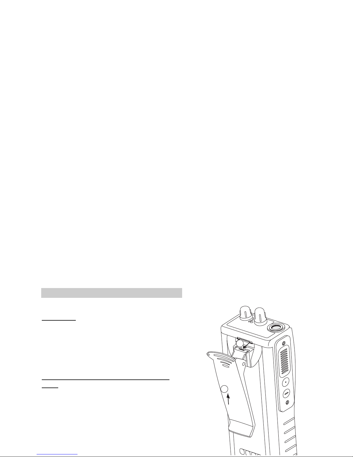
REMOVING & REPLACING THE BELT
CLIP
Removing the belt clip:
1. Depress the metal release tab located on the top of
the belt clip with one hand.
2. With the other hand push the belt clip out of the belt
clip rail.
A
NT
A
NT
CH
VOL
4
3
2
1
maxon
1
2
 Loading...