

Maxon SM-6000 enduro Instructions Manual
SM-6000 Enduro Series
Operating Instructions

About Your SM-6000 Enduro Series Radio
This Maxon SM-6000 Enduro series mobile radio is compatible with LTR
®
trunked and conventional radio systems. It is capable of up to 200 Systems of
32 Groups per System in LTR® Trunked operation and 16 Groups per System
in conventional operation. The operation and functions for the SM-6000
Enduro Series radio are described in this manual.
Please read this manual thoroughly before operating the radio.
Application of some functions described in this manual is determined by the
system you use. Your radio communications Dealer will program your radio
for you to have the greatest number of functions possible relative to your
needs.
Should your have questions regarding the operation of this radio, consult
your radio communications Dealer.
About Topaz3
Topaz3 is the exclusive supplier of Maxon®, Legacy and TruTalk brand
communication products.
Our product line ranges from two-way radios suitable for Business and
Industry (B & I) markets like farm, government, law enforcement, utility, etc.,
to consumer communications equipment for recreational and light-duty
business markets.
Product offerings include a variety of UHF and VHF handheld and mobile
radios, repeaters and RF link modules, as well as FRS (Family Radio Service),
GMRS (General Mobile Radio Service), Citizens Band radios and weather
monitors.
Available accessory items include a variety of carrying cases, spare batteries,
desktop and mobile chargers, earbud speaker microphones, and more for
each radio model.
For additional information on Topaz3 products, visit our website at
www.topaz3.com

Table of Contents
I. FCC RF Exposure Safety Information.................................. 1
II. Safety.............................................................................. 2
III. Unpacking Information...................................................... 3
IV. SM-6000 Enduro Series Radio Features............................... 3
V. Installation Safeguards...................................................... 4
VI. Description of Radio Components....................................... 5
VII. Display Icons and Indicators.............................................. 6
VIII. SM-6000 Enduro Series Radio Operation............................. 7
Power On/Off-Volume.................................................... 7
Trunked Mode Operation................................................ 7
Channel Monitoring - Trunked mode.................................7
System Handshaking - Trunked mode.............................7
Transmitting - Trunked mode............................................7
Receiving - Trunked mode............................................... 8
Transpond - Trunked mode............................................... 8
Conventional Mode Operation........................................ 8
Channel Monitoring - Conventional mode......................... 8
Transmitting - Conventional mode.................................... 9
Receiving - Conventional mode....................................... 9
IX. Busy System Queuing........................................................ 9
X. Multiple-Function Button Descriptions................................ 10
XI. Status Indicators and Audible Alert Tones........................... 13
XII. Scan Modes...................................................................... 14
LTR® Manual Group Scan................................................. 15
LTR® Auto Group Scan..................................................... 15
System Scan................................................................... 15
Conventional Group Scan................................................ 15
XIII. Editing Scan Lists.............................................................. 15
XIV. Conventional Scanning...................................................... 16
Talk Back Scan............................................................... 16
RX Only / TX Disable Scan.............................................. 17
Priority TX Scan.............................................................. 17
Priority Only TX Scan...................................................... 17
Priority Look Back Scan................................................... 17
XV. Nuisance Delete............................................................... 18

XVI. ACC-703 DTMF Microphone Operation.............................. 19
Auto Dial Operation....................................................... 19
Manual Dial Operation................................................... 19
Clearing a Dialed Number............................................... 20
Storing a Number in Memory........................................... 20
Recalling a Stored Number from Memory.......................... 20
Clearing a Stored Number............................................... 20
XVII. Licensing and Service Information..................................... 21
XVIII. Software Copyrights.......................................................... 21
XIX. Maintenance.................................................................... 22
XX. Warranty Statement.......................................................... 23

Contenido
I. Requerimientos de Obediencia a la
Exposicion de RF del FCC............................................... 1
II. Seguridad......................................................................... 2
III. Desempaque y Verificacion del Equipo............................... 3
IV. Caracteristicas del Radio SM-6000 de la Serie Enduro......... 3
V. Medidas de Proteccion en la Instalacion............................. 4
VI. Botones de Control del Radio / Rasgos de Funcionamiento... 5
VII. Iconos e Indicadores de Visualizacion................................ 6
VIII. Operacion del Radio SM-6000 de la Serie Enduro............... 7
Encendido / Apagado-Volumen........................................ 7
Operacion en Modo Troncal............................................ 7
Monitoreo de Canales - Modo Troncal.............................. 7
Establecimiento de Comunicacion del Sistema - Modo Troncal.7
Transmision - Modo Troncal............................................ 7
Recepcion - Modo Troncal.............................................. 8
Transpondedor - Modo Troncal........................................ 8
Operacion de Modo Convencional.................................. 8
Monitoreo de Modo Convencional.................................. 8
Transmision - Modo Convencional................................... 8
Recepcion - Modo Convencional..................................... 9
IX. Espera por Sistema Ocupado............................................. 9
X. Descripciones del Boton de Funcion Multiple..................... 10
XI. Indicadores de Estado y Tonos de Alerta Audible................ 13
XII. Modos de Busqueda.......................................................... 14
Busqueda de Grupo Manual LTR®..................................... 15
Busqueda de Grupo Automatico LTR®............................... 15
Busqueda del Sistema..................................................... 15
Busqueda de Grupo Convencional.................................... 15
XIII. Edicion de las Listas de Busqueda...................................... 15
XIV. Busqueda Convencional.................................................... 16
Busqueda de Respuesta................................................... 16
Recepcion Solamente / Transmision Desactivada............... 17
Busqueda de Transmision Prioridad.................................. 17
Busqueda de Transmision Prioridad Solamente.................. 17
Busqueda de Retreceso Prioritario.................................... 17
XV. Eliminacion de Perturbacionces........................................ 18

XVI. Operacion del Microfono ACC-703 DTMF.......................... 19
Operacion de Discado Automatico................................... 19
Operacion de Discado Manual......................................... 19
Borrar el Numero Marcado.............................................. 20
Almacenar el Numero en la Memoria............................... 20
Volver a llamar un Numero Almacenado en la Memoria.... 20
Borrar un Numero Almacenado........................................ 20
XVII. Licencias e Informacion de Servicio.................................. 21
XVIII. Derechos de Autor del Software........................................ 21
XIX. Mantenimiento................................................................. 22
XX. Declaracion de Garantia................................................... 23

I. FCC RF Exposure Compliance Requirements -
for Occupational Use Only
The Federal Communications Commission (FCC), with its action in General
Docket 93-62, November 7, 1997, has adopted a safety standard for human
exposure to Radio Frequency (RF) electromagnetic energy emitted by FCC
regulated equipment. Topaz3 / Maxon subscribes to the same safety standard
for the use of its products. Proper operation of this radio will result in user
exposure far below the Occupational Safety and Health Act (OSHA) and
Federal Communications Commission limits.
Antennas used for this transmitter must not exceed an antenna gain of 3 dBd.
The radio must be used in vehicle-mount configurations with a maximum
operating duty factor not exceeding 50%, in typical push-to-talk configurations.
This radio is NOT approved for use by the general population in an uncontrolled environment. This radio is restricted to occupational use, work related
operations only where radio operator must have the knowledge to control the
exposure conditions of its passengers and bystanders by maintaining the
minimum separation distance of 5 feet (1.6 meters) between any persons and
the antenna. Failure to observe these restrictions will result in exceeding the
FCC RF exposure limits.
CAUTION - DO NOT transmit for more than 50% of total radio use time (50%
duty cycle). Transmitting more than 50% of the time can cause
FCC RF exposure compliance requirements to be exceeded. The
radio is transmitting when the red LED on the front of the radio
is illuminated. You can cause the radio to transmit by pressing
the P-T-T button on the radios microphone.
CAUTION - DO NOT operate the transmitter of SM -6000 mobile radio
when someone (bystanders) outside the vehicle is within 5 feet
(1.6 meters) of the antenna.
Antenna installation must be limited to the center of the roof-top of a vehicle
where the passengers are below the metallic ground plane (roof-top) to ensure
compliance.
Note: This radio operates in FCC regulated frequency bands. All radios must
be licensed by the FCC before use. Because this radio contains a transmitter,
Federal law prohibits unauthorized use or adjustments of this radio.
1

I. FCC RF Exposure Compliance Requirements -
for Occupational Use Only, continued
This device complies with part 15 of the FCC rules. Operation is subject to
the condition that this device does not cause harmful interference.
WARNING - Frequency band 406 - 406.1 MHz is reserved for use ONLY
as a distress beacon by the US Coast Guard and NOAA. Under
no circumstance should this frequency band be part of the
pre-programmed operating frequencies of this radio.
II. Safety
CAUTION - DO NOT operate the transmitter of any radio unless all RF
connectors are secure and any open connectors are properly
terminated.
CAUTION - DO NOT operate the radio near electrical blasting caps or in an
explosive atmosphere.
CAUTION - All equipment must be properly grounded for safe operation.
WARNING - DO NOT allow children to operate transmitter - equipped radio
equipment.
WARNING - All equipment should be serviced by a qualified technician.
WARNING - It is mandatory that radio installations in vehicles fueled by
liquefied petroleum gas conform to the following standard:
National Fire Protection Association standard NFPA 58 applies
to radio installations in vehicles fueled by liquefied petroleum
(LP) gas with LP gas container in the trunk or other sealed-off
space within the interior of the vehicle. This standard requires
that:
1. Any space containing radio equipment shall be isolated by a seal from
the space in which the LP gas container and its fittings are located.
2. Remote (outside) filling connections shall be vented to the outside.
2

III. Unpacking Information
Remove and carefully inspect the contents of your package(s) for the following
items:
Radio
Microphone
DC Power Supply Cord
Radio Mounting Bracket and Hardware
Microphone Bracket and Hardware
Operating Instructions
If any items are missing or damaged, please contact the radio communications
Dealer from whom you purchased the radio or the Topaz3 Customer Service
Department (1-800-821-7848, Ext. 499).
IV. SM-6000 Enduro Series Radio Features
LTR
®
Trunked radio operation
Conventional radio operation
Backlighted display with icons and up to 9 alphanumeric
characters
Wideband frequency separation
Programmable output power
Programmable wide or narrow channel spacing
Multi-function buttons
Programmable On / Off hook function
Talk Around
Scanning
Priority Scanning
Look Back
Scan list editing
CTCSS / DCS (Conventional operation)
Busy channel lockout
Time-out timer
Home system / home group
3

4
V. Installation Safeguards
WARNING - DO NOT install the radio unit where it will interfere with the
proper operation of automatic collision protection devices (air
bags).
WARNING - DO NOT install the radio unit where it is likely to cause injury in
case of an accident.
Note: This radio is NOT intended for operation in a positive ground vehicle.
A. Select a location for the radio where you will be able to easily see and
reach all the controls and the microphone.
B. Using the radio mounting bracket as a template, mark with a pencil the
locations where the bracket securing screws will be placed.
Note: Before drilling holes in the vehicle, verify that there is nothing that could
be damaged or get in the way by drilling and putting screws in this location. It is
better to use existing passages in the dashboard, trunk, and floor for routing
the cable, thus avoiding excessive drilling and possible damage.
C. After drilling holes for the mounting bracket, attach the bracket to the
mounting surface by using the two (2) large Phillips head screws
provided.
D. Attach the radio to the mounting bracket using the black screw knobs
(located on each side of the radio) along with the two (2) spring-lock
washers and two (2) large flat washers provided. If necessary, connect
the power supply cord for the radio before mounting the radio to the
bracket.
Note: Depending on the radio mounting location, it may be more convenient
to attach the microphone bracket to the radio before installing the radio.
E. Using the two (2) small Phillips head screws provided, mount the micro-
phonebracket to the side of the radio. There are two options for
installing the microphone bracket, allowing the on-hook placement
of the microphone from either the top or the front of the bracket.
F. Push the modular microphone connector into the microphone jack
(located on the front of the radio) until you hear a click.
CAUTION - Some electronic fuel injection, anti-lock braking systems, cruise
controls, and vehicle alarms may be subject to interference
from radio frequency energy or may malfunction due to a lack
of protection from RF energy. If the vehicle contains such equipment, consult your radio communications Dealer for assistance
or advice in determining whether the electronic equipment in
the vehicle will operate properly when the radio is transmitting.
A B C D
E
F G H I
V. Installation Safeguards, continued
You must purchase an antenna for proper operation of the radio. Consult your
radio communications Dealer to determine which antenna is suitable.
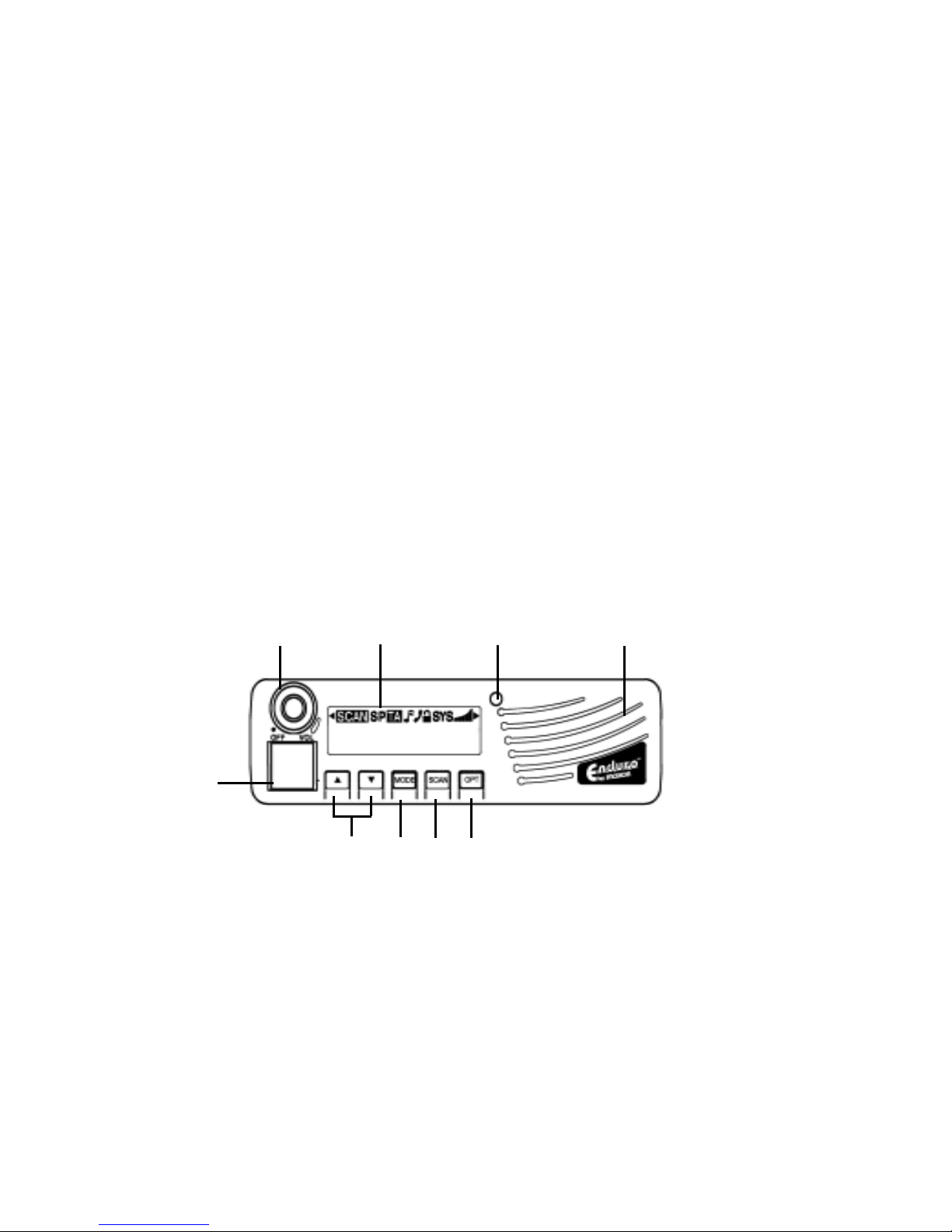
VI. Description of Radio Components
A. On / Off - Volume Knob Turns the radio on/off and controls the audio level.
B. Display Backlighted display with icons and up to 9 alphanumeric
characters.
C. LED Indicator Tri-colored light indicates status of radio.
D. Speaker 8 Ω Internal speaker allows received messages to be heard.
E. Microphone Connector 8-pin RJ-5 jack accepts microphone plug and is
used for radio programming.
F. IUp / JDown Selection Buttons Select Systems, Groups, option functions.
G. Mode Select Button Toggles among Systems, Groups, call missed
(CALL), and display brightness (BRIGHT). Also returns radio to your
home System / home Group.
H. Scan Select Button Enables / disables scan functions; also toggles
between scan and priority scan modes.
I. Option Select Button Enables / disables optional radio functions; also
enables scrolling when using the I/ J selection buttons.
(Back view on next page)
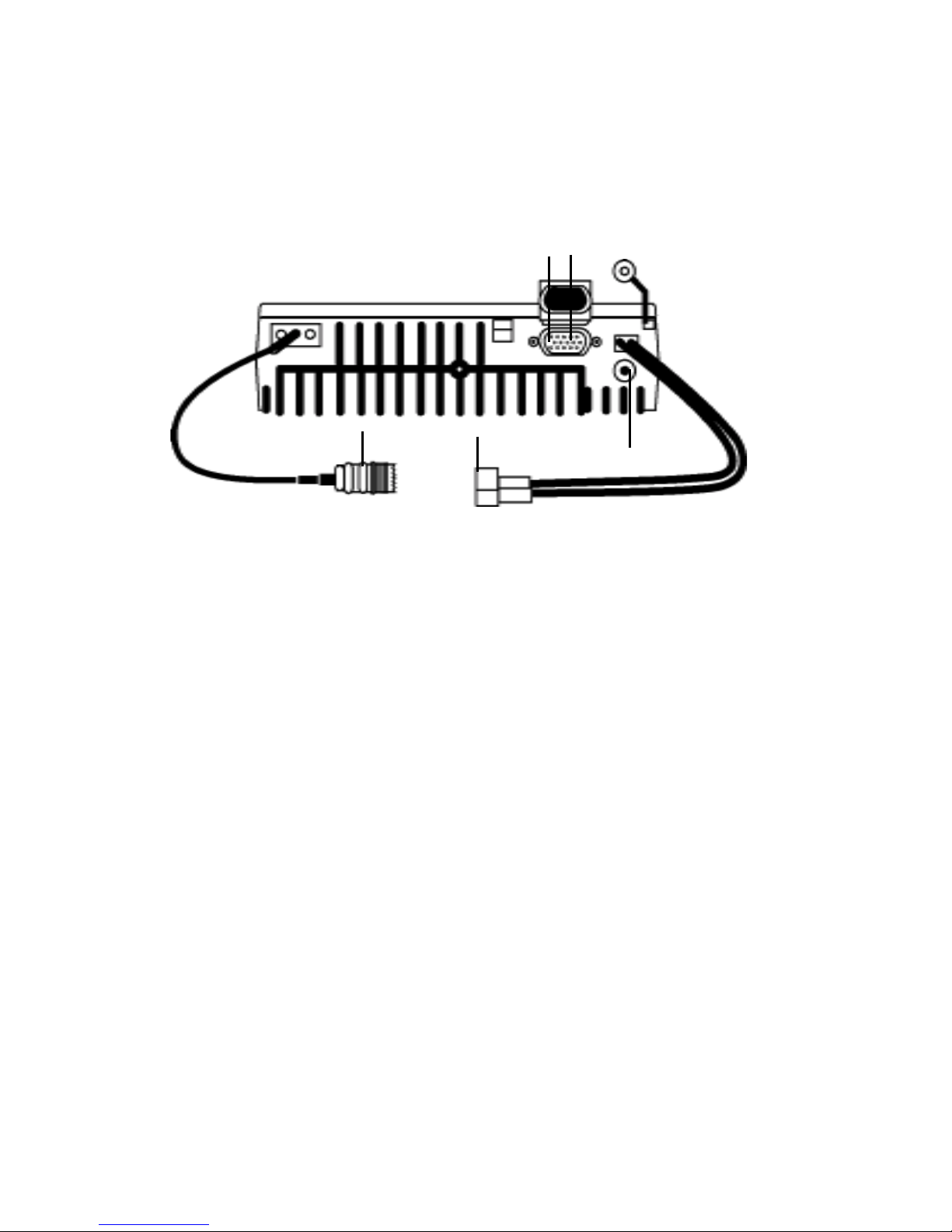
J. High Density DB-9 Connector Option connector that supplies or
receives audio levels. Can also be used with an external or internal
radio modem to make the radio capable of sending or receiving
mobile data information.
K. Ignition Sense (located on high-density DB-9 connector) To power
radio on and off via the vehicles ignition system.
5
6
VI. Description of Radio Components, continued
L. External Auxiliary Speaker Connector 3.5mm jack is used for connecting
an external speaker.
M. DC Power Cord 13.8 VDC polarized plug (for use in negative ground
vehicle electrical systems only).
N. Antenna Receptacle Requires a 50 Ω PL-259 type load (sold separately).
Not Shown
Mounting Bracket with Hardware Used to mount the radio inside the
vehicle.
Microphone Hanger Used to hang the microphone; also used to enable /
disable the CTCSS / DCS squelch functions.
VII. Display Icons and Indicators
Scan Indicates scan mode is active.
S Indicates included in scan list or in scan edit
mode. When displayed under OPT list, indicates
that an option has been selected.
P Indicates Priority scan mode and assigned priority
channel.
TA Indicates Talk Around mode is active.
Musical note icon
NN
NN
N (Continuous) Indicates active beep tones; (flashing)
indicates the auxiliary speaker is active.
Phone icon
ZZ
ZZ
Z (Continuous) Indicates interconnect phone mode;
(flashing) indicates a call missed.
SYS Indicates System mode is active.
Volume indicator Indicates current volume level.
J K
N M L

VIII. SM-6000 Enduro Series Radio Operation
Power On/Off - Volume
Turn the radio on by rotating the on/off - volume control clockwise until you
hear a click. If this function has been enabled via Dealer programming you
will hear the self test alert tone. SM-6000 will briefly appear in the display.
Turn the radio off by rotating the control counterclockwise until it clicks.
Trunked Mode Operation
Your Maxon SM-6000 Enduro Series radio can be programmed to operate in
both trunked and conventional modes. There are only a few differences in their
operation, detailed in the following paragraphs.
Channel Monitoring - Trunked mode
While on a trunked system, channel monitoring is performed automatically
by the radio transceiver. In both trunked and conventional systems, operation
may vary from system to system. Your radio communications Dealer will be
able to assist with particular operational parameters and procedures for the
various systems and functions.
System Handshaking - Trunked mode
In a trunked system, when the P-T-T bar on the microphone is pressed, a
handshaking occurs. This establishes communication between the radio
and trunked system. When the LED indicator steadily glows red, voice
transmission may begin. If your radio communications Dealer has enabled
the clear to talk tone option, the radio will emit a short tone signaling voice
transmission may occur.
Transmitting - Trunked mode
A. Using the I or J buttons located on the front of the unit, select the
desired system and group.
B. Ensure that the microphone is plugged securely into the microphone
jack located on the front of the unit. Press and hold the P-T-T bar on
the side of the microphone.
C. Listen for the clear to talk tone (or wait for the LED indicator to steadily
glow red). Holding the microphone 1 or 2 inches from your mouth,
begin speaking clearly and distinctly. Press the P-T-T bar continuously
while talking.
D. As soon as your message is complete, release the P-T-T bar and listen for
a response.
7

VIII. SM-6000 Enduro Series Radio Operation, continued
Receiving - Trunking mode
A. Select the desired system and system group.
B. When a message is received, the LED indicator will glow green.
C. Respond to the message by removing the microphone from its hook and
pressing the P-T-T bar. Follow the transmitting instructions from prior
page.
Note: If scanning modes are enabled, be sure to respond before scanning
resumes. If you do not, another call may be received and the selected system
and group may have to be changed. Scanning is indicated by scan mode
icons. Refer to the Scan Modes section in this manual for more information.
Transpond - Trunked mode
Transpond is a Dealer programmable feature. If transpond has been enabled
by your Dealer, your radio will automatically send (transpond) an acknowledgement to the system, indicating that your radio has received a transmission.
Conventional Mode Operation
Your Maxon SM-6000 Enduro Series radio can be programmed to operate
in conventional mode. Conventional mode may or may not require a
conventional repeater System. Radio-to-radio communication can also be
accomplished in Conventional operation. How the conventional mode is
programmed is determined by your radio communications Dealer.
Channel Monitoring - Conventional mode
A. Using the I or J buttons located on the front panel of the radio, select
the desired conventional system and group channel.
B. In accordance with FCC rules, it is necessary in a conventional system
to monitor a channel for activity before a transmission. Monitor the
channel by pressing the OPT (option) button located on the front panel
and scrolling with the OPT button until MONITOR appears on screen.
Press the OPT button once to begin the monitor function; press OPT a
second time to turn off the monitor function. Monitoring of a channel
can also be accomplished by checking the LED indicator. If a continuous yellow glow is observed, you cannot transmit. When the yellow
glow ceases, you can begin transmitting. In conventional systems, there
is no system handshaking - voice transmission may start immediately.
8

VIII. SM-6000 Enduro Series Radio Operation, continued
Transmitting - Conventional mode
A. Press and hold the P-T-T bar located on the side of the microphone.
The LED indicator will glow red. Holding the microphone 1 or 2 inches
from your mouth, speak clearly and distinctly. Press the P-T-T bar
continuously while talking.
B. As soon as your message is complete, release the P-T-T bar and listen for
a response.
Receiving - Conventional mode
A. Select the desired system and system group channel.
B. When a message is received, the LED indicator will continuously glow
yellow or green, depending on whether the CTCSS tone or DCS has
been programmed.
C. Respond to the message by removing the microphone from its hook and
pressing the P-T-T bar. Follow the transmitting instructions above.
If scanning modes are enabled, be sure to respond before scanning resumes. If
you do not, another call may be received and the selected channel may have
to be changed. Scanning is indicated by the scan mode icons. Refer to the
Conventional Scanning section in this manual for more information.
IX. Busy System Queuing
Busy system queuing is available for both trunked and conventional system
operation. If enabled by your radio communications Dealer, busy system
queuing will monitor the system for activity. Once a system becomes available,
it will automatically be accessed and held for a period of time (predetermined
by programming), enabling you to transmit on this system. An audible indicator
tone will sound and the LED indicator will flash yellow when queuing has
begun and again when the system has been accessed. While busy system
queuing is active, the word QUEUING will appear in the display.
9

X. Multiple-Function Button Descriptions
Your SM-6000 Enduro Series radio has five (5) multiple-function buttons
located on the front panel. If enabled during programming by your radio
communications Dealer, you will hear an audible beep every time you
press a button.
IUp / J Down Selection Buttons
These buttons enable you to scroll up or down your pre-programmed
systems, groups or option functions. A press-and-release will step once,
a press-and-hold will scroll until the button is released. All system and
group names are pre-programmed by your Dealer and will be shown
in the display as you scroll through them .
MODE Select Button
This button enables you to toggle between system, group, display brightness
(BRIGHT) , call missed (CALL) and will return you to your home system /
home group. A press-and-release will toggle between system, group, display
brightness and call missed modes. A press-and-hold will return the radio to
home system / home group. The home system /home group names will be
shown in the display.
Display Brightness
Display brightness mode allows you to change the brightness of the
display. Press and release the MODE button until the word BRIGHT
appears. Press and release the I or J buttons to change the brightness
to desired level (4 settings to choose from). To go back through the
brightness levels, continue to press the I or Jbutton. The radio will
display the last chosen brightness level, and will return to your
previously selected system or group.
Call Missed
Call missed mode, a Dealer programmable function, enables you to check
for calls you may have missed while away from your radio. A continuous
flashing
ZZ
ZZ
Z icon indicates a call or calls have been missed and are stored
in the missed call list.
To check for missed calls, press and release the MODE button until the
word CALL is shown in the display. Press the I or J buttons to view
the missed caller or group name. Once viewed, press the microphone
P-T-T bar to acknowledge the missed call; that call will be deleted from
your call list. Up to 8 unanswered calls can be stored; more than 8 calls
10

11
X. Multiple-Function Button Descriptions, continued
Mode Selection Button, Call Missed, continued
will be removed from the list, beginning with the oldest call. Press the
MODE button a second time to remove any calls not acknowledeged
and exit the call missed list.
Note: Scanning will be disabled when your call list is being accessed. You will
not be able to transmit on other systems or groups until the missed calls have
been acknowledged.
Scan Button
This button selects scan or priority scan mode. A press-and-release will enable
scanning functions. A press-and-release will also disable the selected scan
function. If normal scan is programmed, the SCAN icon will be displayed; if
priority scan is programmed, both the SCAN and P icons will be displayed.
OPT (Option) Button
This button allows you to enable or disable a selected optional function. A
press-and-release, unless specified otherwise, will enable or disable the currently
selected function: talk around (TALKARNd), monitor (MONITOR), horn
and lights (HORN LT), auxiliary (AUX), public address (P/A), exit (EXIT).
A press-and-release followed immediately by a press-and-hold will allow
selection of option functions using the I or J buttons. Once an option
appears in the display, a second key press of OPT will select that option to
be enabled under the OPT button. If no button press is detected, the option
will not be enabled and the radio will resume previous operation. All option
indications will be displayed by either an icon or in the LCD. When reviewing
programmed options, an S icon will appear above the feature selected and
enabled.
Note: More than one feature can be enabled in the option mode.
Talk Around
Talk around mode is available for trunked or conventional operation. If
previously selected as an OPT button function, this option enables you
to talk from radio to radio, bypassing the system. This is useful when your
radios are out of range of any system. Talk around can be activated by
pressing the OPT button. The TA icon will appear in the display. To
deactivate talk around, press and release the OPT button a second time.

X. Multiple-Function Button Descriptions, continued
OPT (Option) Button, continued
Monitor
Monitor mode is only available for conventional operation. If selected as
an OPT button function, it allows you to open the radios squelch to listen
for activity before attempting transmission on a conventional systems
group. Monitor also defeats CTCSS and DCS squelch functions. Monitor
can be activated by a press-and-release of the OPT button, thus opening
the radios squelch. A second press-and-release of the OPT button
will close the radios squelch. When the monitor is active, the word
MONITOR is displayed.
Horn and Lights
If selected as an OPT button function, the horn and lights mode will alert
you of a call by honking your vehicles horn or flashing its lights (depending upon the Dealers installation hook up). Your vehicles horn or lights
will be activated with a four (4) step alert with the longest duration
lasting 4 seconds. This pattern will be repeated three more times, then
stop. After the horn and lights function has stopped, the radios LED will
flash in a similar pattern, alternating between green and yellow, to alert
you that a call has been missed. Turning the radio off, pressing the
microphone P-T-T bar, removing the microphone from its hook, or
pressing any button will end this function. It must be reactivated if any
of these operations have taken place. The horn and lights function is
activated by a press-and-release of the OPT button. When it is activated,
the word HORN-LT will be shown in the display. A second press-andrelease of OPT will deactivate the horn and lights function. The horn and
lights function can be used in conjunction with the Dealer programmable
call missed feature which stores up to 8 unanswered calls.
Auxiliary
If selected as an OPT button function, auxiliary mode will enable or
disable an external speaker option which may have been added to
your radio. When activated by a press-and-release of the OPT button,
the internal speaker of the radio will be disconnected and the externally
attached speaker will become active. A second press-and-release will
return to radios internal speaker. When AUXILIARY is activated, the
NN
NN
N icon will flash. The auxiliary option can be activated with all other
options. When other options are selected, the attached external speaker
will always be active until the other selected option is disabled.
12
 Loading...