

Maxon SM5402 Instructions Manual
SM5402
Operating
Instructions

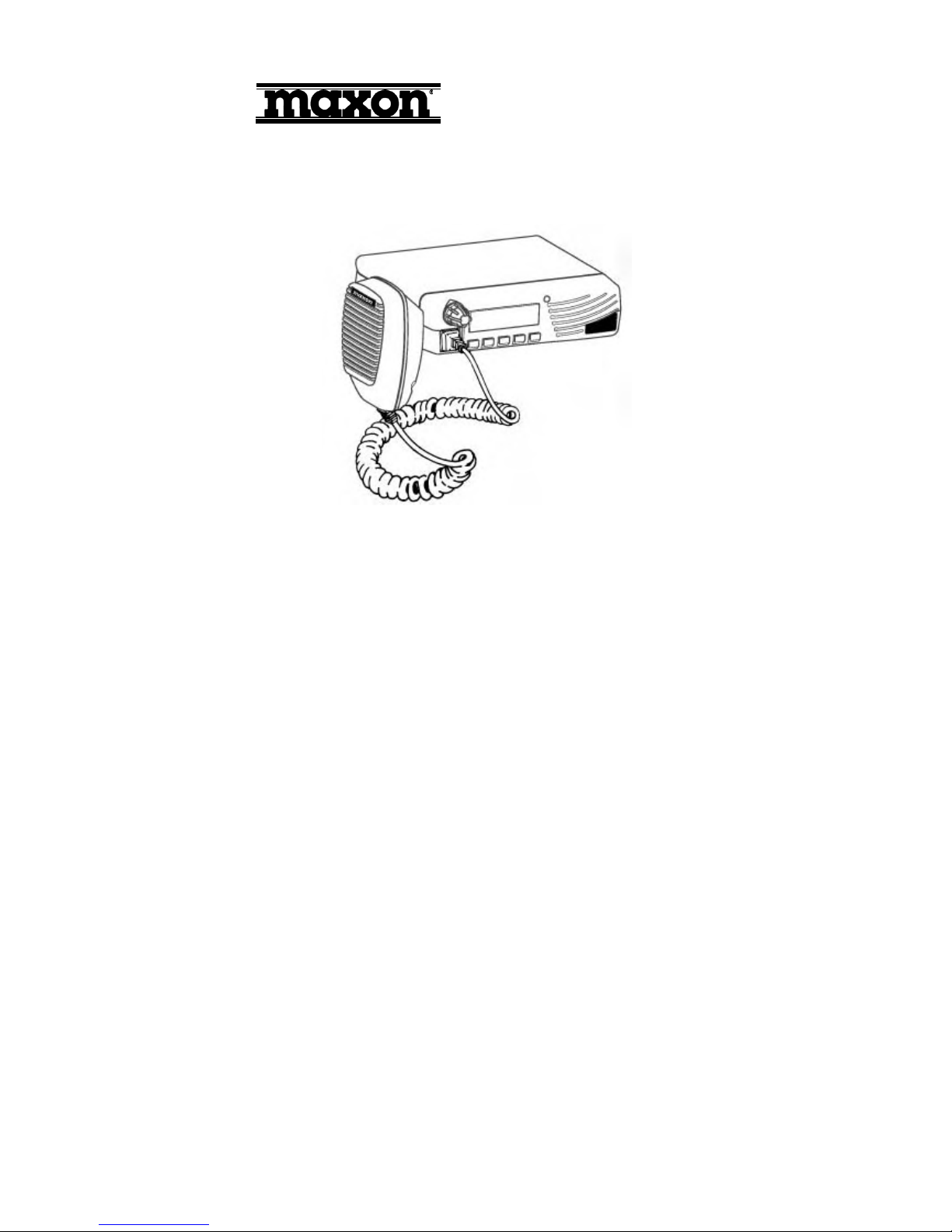
About Your SM5402 Radio
Maxon's SM5402 mobile radio are Compatible, Conventional radio system operation. The SM5402
is capable of up to 208 channels 13 Groups per system in conventional operation.
The operation and functions for the SM5402 radios are described in this manual.
We urge you to thoroughly read this manual before operating the radio.
Application of some functions described in this manual is determined by the system you use.
Your Maxon Dealer will program your radio so that you have the greatest number of functions
possible relative to your needs.
Should you have questions regarding the operation of the radio, please consult your Maxon Dealer.
About Maxon
Maxon is a world-respected name in professional FM two-way radio equipment operating in the
UHF, VHF and 800 MHz frequencies; personal two-way communication devices, including the
popular FRS (Family Radio Service) and GMRS radios; and a variety of wireless communication
products (two-way voice messaging handsets, Wireless Local Loop terminals, etc.).
Safety Information
The Federal Communications Commission (FCC), with its action in General Docket 93-62,
November 7, 1997, has adopted a safety standard for human exposure to Radio Frequency (RF)
electromagnetic energy emitted by FCC regulated equipment. Maxon subscribes to the same safety
standard for the use of its products. Proper operation of this radio will result in user exposure far
below the Occupational Safety and Health Act and Federal Communications Commission limits.
WARNING - The antenna shall be mounted in the centre of the vehicle roof, or trunk, to ensure a
minimum separation distance of 110cm, or 60cm, respectively t o persons who may
stand close to the vehicle. And the antenna may only be mounted on metal body motor

vehicles or vehicles with appropriate ground planes. And must not be co-located or
operation in conjunction with any other antenna or transmitter.
WARNING - This radio has been tested and complies with the FCC RF exposure limits for
“Occupational Use Only.” In addition, your FM radio complies with the following
standards and guidelines with regard to RF energy and electromagnetic energy levels
and evaluation of such levels for exposure to humans :
- FCC OET Bulletin 65 Edition 97-01 supplement C, Evaluating compliance with FCC
guidelines for Human Exposure to Radio Frequency Electromagnetic Fields.
- American National Standards Institute (C95.1-1992), IEEE standard for Safety levels
with respect to human exposure to radio frequency electromagnetic fields, 3 kHz to
300 GHz.
- American National Standards Institute (C95.3-1992), IEEE recommended practice for
the measurement of potentially hazardous electromagnetic fields – RF and Microwave.
- DO not operate the radio without a proper antenna attached, as this may damage the
radio and may also cause you to exceed FCC RF exposure limits. A proper antenna is
the antenna supplied with this radio by the manufacturer or an antenna specifically
authorized by the manufacturer for use with this radio.
- ALWAYS use Maxon authorized accessories. Use of unauthorized accessories can
cause the FCC RF exposure compliance requirements to be exceeded.
- DO not transmit for more than 50% of total radio use time (50% duty cycle).
Transmitting more than 50% of the time can cause FCC RF exposure compliance
requirements to be exceeded.
The information listed above provides the user with the information needed to make him or her
aware of RF exposure, and what to do to assure that this radio operates within the FCC RF
exposure limits.
During transmissions, your Radio generates RF energy that can possibly cause interference with
other devices or systems. To avoid such interference, turn off the radio in areas where signs are
posted to do so.
WARNING - It is mandatory that radio installations in vehicles fueled by liquefied petroleum gas
conform to the following standard: National Fire Protection Association standard
NFPA 58 applies to radio installations in vehicles fueled by liquefied petroleum (LP)
gas with LP gas container in the trunk or other sealed-off space within the interior of
the vehicle. This standard requires that:
1 Any space containing radio equipment shall be isolated by a seal from the space
in which the LP gas container and its fittings are located.
2 Remote (outside) filling connections shall be vented to the outside.

WARNING - DO not operate the transmitter of a mobile radio when someone outside the vehicle is
within two feet (0.6 meter) of the antenna.
WARNING - DO not allow children to operate transmitter - equipped radio equipment.
WARNING - DO not allow operate the transmitter in areas that are sensitive to electromagnetic
radiation such as hospitals, aircraft, and blasting sites.
CAUTION - DO not operate the radio near electrical blasting caps or in an explosive
atmosphere.
CAUTION - DO not operate the transmitter of any radio unless all RF connectors are secure and
any open connectors are properly terminated.
All equipment must be properly grounded for safe operation.
All equipment should be serviced by a qualified technician.
NOTE: This radio operates in FCC regulated frequency bands. All radios must be
licensed by the FCC before use. Because this radio contains a transmitter, Federal law
prohibits unauthorized use or adjustments of this radio.

Unpacking Inforamtion
Remove and carefully inspect the contents of your package(s) for the following items:
Radio
Microphone
DC Power Supply Cord
Radio Mounting Bracket and Hardware
Microphone Bracket and Hardware
Operating Instructions
SM5402 Features
z Conventional radio operation
z 9 character display with icons
z Wideband frequency separation
z Programmable output power
z Programmable 12.5 / 25 kHz channel spacing
z Multiple-function five button keypad
z Programmable On / Off hook function
z Talk Around
z Scanning
z Priority Scanning
z Look Back
z Scan list editing
z CTCSS / DCS / DTMF / 2-Tone / ANI (Conventional operation)
z Busy channel lockout
z Time-out timer

General
Performance Specifications FTZ 17TR2049 July 88
TIA-603
IEC 68 Series
EC 529 IP54
MIL STD 810 F
Band (Tx & Rx) (Switching range without retuning)
UHF (U2) 440 – 470MHz
Channel Spacing 12.5kHz, / 25kHz (programmable)
(12.5, /25kHz switchable by CPU control)
RF Output Power 45W nominal (+/-10%)
Modulation Type F3E
Audio Power 6W (Internal 16W speaker)
Intermediate Frequencies 45.1MHz First I.F., 455kHz Second I.F.
Number of Channels 208
Frequency Source PLL Synthesiser
Frequency Stability +/- 2.5ppm
Power Supply 13.8Vdc nominal
10.8Vdc minimum (extreme)
15.6Vdc maximum (extreme)
Current Consumption OFF <10 A
Standby (muted) <140mA
Unmuted with 25% AF power <350mA
Unmuted with 50% AF power <450mA
Unmuted with 100% AF power <570mA
Transmit @ 5W RF Low output <5.0A

Transmit @ 40W RF Normal output <10.0A
Transmit @ 45W RF High output <11.0A
Environmental
Temperature Range
Operating +15 to +35°C (nominal)
-30 to +60°C (extreme),
Storage Temperature Range -40 to +80°C (storage)
Humidity EIA/TIA 603 (95%)
Protection against ingress of IEC 529 IP54
dust and water
Vibration BS2011 : Part 2.1Fc IEC 68-2-6
Part 2.1Fd IEC 68-2-34
Robustness Mil Std 810 F
ESD 20kV (C-MIC = 15kV)
Physical Dimensions 175(W) x 158(D) x 48(H) mm
Weight 1.44kgs
Programmer SMP 6001
Reliability Analysis
MTBF 15,000 Hours MIL-HDBK-217F.
Ground benign. Parts stress
method.
MTTR 30 minutes average time to rework
any SMD component and
reassemble.

Installation Safeguards
WARNING -DO NOT install the radio unit where it would interfere with the proper operation of
automatic collision protection devices (air bags).
WARNING - DO NOT install the radio unit where it would likely cause injury in case of accident.
NOTE: The radio is not intended for operation in a positive ground vehicle.
1. Select a location for the radio where you can easily see and reach all controls,
A. including the microphone.
2. Using the radio mounting bracket as a template, mark with a pencil the locations
A. where the bracket securing screws will be placed.
NOTE -Before drilling holes in the vehicle, verify that there is nothing that could be
damaged or get in the way by drilling and putting screws in this location. It is better to
use existing passages in the dashboard, trunk, and floor for the routing cable, thus
avoiding excessive drilling.
After drilling holes for the mounting bracket, attach bracket to the surface by using the
two large Phillips head screws provided.
3. Install the radio unit to the bracket using the black screw knobs (located on each side
of the radio) along with the two spring lock washers, and two large flat washers
provided.
NOTE -Depending on the radio mounting location, it may be more convenient to install the
microphone bracket before installing the entire radio unit.
4. Mount the microphone bracket to the most convenient side of the radio unit, using the
two small Phillips head screws provided. There are two options for installing the
microphone bracket, allowing the on-hook placement of the microphone from either
the top or the front of the bracket.
5. Connect the DC power supply cord to the radio. If necessary, the power supply cord
may be connected before mounting the radio unit to the radio bracket.
6. Push the modular microphone connector into the microphone jack (located in the front
of the radio unit) until a click is heard.
CAUTION -Some electronic fuel injection, anti-skid braking systems, cruise controls, and vehicle
 Loading...