

Maxon SM5102 Service Manual
SM5102 Radio
SM5102 (146MHz~174MHz)
MOBILE RADIO SERVICE MANUAL

MaxonSM5102Radio
1.INTRODUCTION
About Your SM5102 Radio
Maxon's SM5102 mobile radio are Compatible. Conventional radio system operation. the SM5102 is capable of
up to 208 channels 13 Groups per system in conventional operation.
The operation and functions for the SM5102 radios are described in this manual.
We urge you to thoroughly read this manual before operating the radio.
Application of some functions described in this manual is determined by the system you use. Your Maxon
Dealer will program your radio so that you have the greatest number of functions possible relative to your
needs.
Should you have questions regarding the operation of the radio, please consult your Maxon Dealer.
About Maxon
Maxon is a world-respected name in professional FM two-way radio equipment operating in the UHF, VHF
and 800 MHz frequencies; personal two-way communication devices, including the popular FRS (Family
Radio Service) and GMRS radios; and a variety of wireless communication products (two-way voice
messaging handsets, Wireless Local Loop terminals, etc.).
Safety Information
The Federal Communications Commission (FCC), with its action in General Docket 93-62, November 7, 1997,
has adopted a safety standard for human exposure to Radio Frequency (RF) electromagnetic energy emitted by
FCC regulated equipment. Maxon subscribes to the same safety standard for the use of its products. Proper
operation of this radio will result in user exposure far below the Occupational Safety and Health Act and Federal
Communications Commission limits.
Safety Information, Continued
WARNING - It is mandatory that radio installations in vehicles fueled by liquefied petroleum gas conform to
the following standard: National Fire Protection Association standard NFPA 58 applies to radio installations in
vehicles fueled by liquefied petroleum (LP) gas with LP gas container in the trunk or other sealed-off space
within the interior of the vehicle. This standard requires that:
1 Any space containing radio equipment shall be isolated by a seal from the space
in which the LP gas container and its fittings are located.
2 Remote (outside) filling connections shall be vented to the outside.
WARNING - DO NOT operate the transmitter of a mobile radio when someone outside the vehicle is within two
feet (0.6 meter) of the antenna.
WARNING - DO NOT allow children to operate transmitter - equipped radio equipment.
CAUTION - DO NOT operate the radio near electrical blasting caps or in an explosive atmosphere.
CAUTION - DO NOT operate the transmitter of any radio unless all RF
connectors are secure and any open connectors are properly
terminated.
All equipment must be properly grounded for safe operation.
All equipment should be serviced by a qualified technician.
NOTE: This radio operates in FCC regulated frequency bands. All radios must be licensed by the FCC
before use. Because this radio contains a transmitter, Federal law prohibits unauthorized use or
adjustments of this radio.

Maxon SM5102Radio
This device complies with Part 15 of the FCC Rules. Operation is subject to the condition that this
device does not cause harmful interference.
Unpacking Inforamtion
Remove and carefully inspect the contents of your package(s) for the following items:
Radio
Microphone
DC Power Supply Cord
Radio Mounting Bracket and Hardware
Microphone Bracket and Hardware
Operating Instructions

MaxonSM5102Radio
WARNINGS
1. Components containing beryllium oxide are used in the equipment. Dust from this material is a
health hazard if inhaled or allowed to come into contact with the skin. Great care must be taken
when handling these components. They must not be broken or subjected to excessive heat.
2. Never operate the radio transmitter without the correct Maxon antenna, or a suitable artificial
load, connected.
3. Never modify a radio, or accessory, except as instructed in the Service Manual, Engineering
Bulletins or formal communication as this may invalidate any warranty, guarantee or type
approval.
4. Do not operate this equipment in environments containing explosive materials or vapour.

Maxon SM5102Radio
TABLE OF CONTENTS
1.SPECIFICATION
1.1 General
1.2 Transmitter
1.3 Receiver
2.MAINTENANCE & REPAIR
2.1 Introduction
2.1.1 Test Equipment Connection
2.1.2 Transmitter Performance Tests
2.1.3 Test Equipment Connection
2.1.4 Transmitter Performance Tests
2.1.5 Receiver Performance Tests
2.2 Alignment
2.2.1 Disassembly and Re-assembly of the Radio
2.2.2 PLL Alignment
2.2.3 Transmitter Alignment
2.2.4 Receiver Alignment
2.2.5 Receiver Performance Tests
3.DETAILED FUNCTIONAL DESCRIPTION
3.1 UHF Transmit
3.2 UHF Receive
3.3 Control PCB
3.4 Front Panel PCB
3.5 SOFTWARE CONTENTS
4.TROUBLESHOOTING GUIDE
4.1 BASEDIAGRAM

MaxonSM5102Radio
1.1 General
Performance Specifications FTZ 17TR2049 July 88
TIA-603
IEC 68 Series
EC 529 IP54
MIL STD 810 C
Band (Tx & Rx) (Switching range without retuning)
VHF (V2) 146 – 174MHz
Channel Spacing 12.5kHz, / 25kHz (programmable)
(12.5, /25kHz switchable by CPU control)
RF Output Power
High Power 50W nominal
(+/-10%)
Low Power 5W nominal
(+/-10%)
Modulation Type F3E
Audio Power 4W (Internal 16 Ω speaker)
Intermediate Frequencies 45.1MHz First I.F.,
455kHz Second I.F.
Number of Channels 208
Frequency Source PLL Synthesiser
Frequency Stability +/- 2.5ppm
Power Supply 13.8Vdc nominal
10.8Vdc minimum (extreme)
15.6Vdc maximum (extreme)
Current Consumption OFF <10µA
Standby (muted) <140mA
Unmuted with 25% AF power <350mA
Unmuted with 50% AF power <450mA
Unmuted with 100% AF power <570mA
Transmit @ 5W RF Low output <5.0A
Transmit @ 40W RF Normal output <10.0A
Transmit @ 45W RF High output <11.0A
Environmental
Temperature Range
Operating +15 to +35°C (nominal)
-30 to +60°C (extreme),
Storage Temperature Range -40 to +80°C (storage)
Humidity EIA/TIA 603 (95%)
Protection against ingress of IEC 529 IP54
dust and water

Maxon SM5102Radio
Vibration BS2011 : Part 2.1Fc IEC 68-2-6
Part 2.1Fd IEC 68-2-34
Robustness Mil Std 810 C
ESD 20kV (C-MIC = 15kV)
EMC EMC Directive 89/336/EEC May 89
ETS 300.279
Physical Dimensions 175(W) x 158(D) x 48(H) mm
Weight 1.44kgs
Programmer SMP 6001
Reliability Analysis
MTBF 15,000 Hours MIL-HDBK-217F.
Ground benign. Parts stress method.
MTTR 30 minutes average time to rework any SMD
component and reassemble.

Maxon SM5102Radio
1.2 Transmitter
Test Method is ETS 300.086 2001 unless stated.
Performance without Sub-Audio Modulation
Power Output
High Power 50W nominal
Low Power 5W nominal
Audio Freq. Deviation
Nominal Peak
12.5kHz +/-1.5kHz +/-2.5kHz
20kHz +/-2.4kHz +/-4.0kHz
25kHz +/-3.0kHz +/-5.0kHz
With or without audio sub-modulation (10% peak
deviation)
Audio Characteristic
(Method as FTZ17 TR 2049 July 1988)
Modulation Type F3
Within +1/-3dB of limit at 1kHz:
300Hz to 2.55kHz for 12.5kHz channel spacing
300Hz to 3.0kHz for 20 / 25kHz channel spacing
Modulation Type G3
Within +1/-3dB of 6dB/octave limit wrt 1kHz:
300Hz to 2.55kHz for 12.5kHz channel spacing
300Hz to 3.0kHz for 20 / 25kHz channel spacing
Tx Spurious Emission (conducted and radiated)
Below 1GHz Better than –36dBm
1 – 4GHz Better than –30dBm
Mic Sensitivity
At Accessory/Mic connector
15mV +/- 3.5mV
Values for 60% peak dev.
Transmitter Audio Distortion (Without CTCSS)
1kHz < 5% (nominal)
Transmitter Audio Distortion (With CTCSS)
1kHz < 8% (nominal)
Audio frequency = 1kHz, with any CTCSS freq.
combined.
Hum and Noise (Residual Modulation)
Method as FTZ 17 TR 2049 July 1988
Better than 40dB (with PSOPH)
Sub Audio Tones - CTCSS
Tone Range 67 to 250.3Hz @ 0.3%
accuracy
Tone Standard RS-220A EIA
Non-Standard 50 to 260Hz @ 0.3%
Tones accuracy
Nominal Tone 10% (8-15%) Pk Sys Dev.
Deviation
Sub Audio Tones - DCS
Tone Standard Normal and Inverted
Tone Deviation 10% ( 3% Pk System Dev. (UK)
1.3 Receiver
Test Method is ETS 300.086 2001 unless stated.
Performance without Sub-Audio Modulation
Sensitivity
12dB SINAD UHF: Better than –117dBm
12dB SINAD VHF: Better than –118dBm
Amplitude Characteristic Within +/- 3dB
Adjacent Channel Selectivity
Nominal
12.5kHz Better than 60dB
25kHz Better than 70dB
Spurious Response Rejection
Better than 70dB (100kHz – 4GHz)
Intermodulation Response Rejection
+/- 25 / 50kHz Better than 65dB
+/- 50 / 100kHz Better than 65dB
Rx Spurious Emissions (radiated) - nominal
9kHz – 1GHz Better than –57dBm
1GHz – 4GHz Better than –47dBm
AF Power 6W max.
AF Distortion – Method as FTZ 17 TR 2049
1kHz < 5% (nominal)
Rx Hum and Noise
Method as TIA / EIA-603
12.5kHz <40dB No PSOPH
25kHz <40dB No PSOPH
Sub Audio Tones - CTCSS
Tone Range 67 to 250.3Hz @ 0.3%
accuracy
Tone Standard I-ETS 300.219
Non-Standard 50 to 260Hz @ 0.3%
Tones accuracy
Decode Sensitivity
Method (Decrease Signal Level, @ 10% peak
dev. with no audio tone)
All Tones <=9dB SINAD
Maxon SM5102Radio
2 MAINTENANCE & REPAIR
2.1 Introduction
This section covers the tests which should be undertaken prior to handover of the radio to the end
user. All of the following tests can be carried out without having to gain access to the interior of the
radio.
Recommended Test Equipment
The alignment and performance test procedures assume the use of the following equipment. The
functions of most of the equipment may be found in a “Communications Test Set”. This type of
equipment is available from a number of test equipment manufacturers.
Throughout this book reference will be made to the use of the Communications Test Set. Where
applicable, the equivalent discrete item of test equipment may be used. For example, if measuring
power, a stand-alone power meter and a dummy load could be used instead of the Test Set
Discrete Test Equipment
RF Signal Generator
RF Power Meter
RF Frequency Counter
Spectrum Analyser and notch filter (optional)
Audio Signal Generator
Audio Power Meter
SINAD Meter
Modulation Meter
Oscilloscope
Voltmeter
DC Power Supply, 0 - 15V 2A min.
Combined Equipment
Communications Test Set (e.g. Marconi
TF2955, Stabilock 4015 or similar).
Accessories
PM200V2 Microphone.
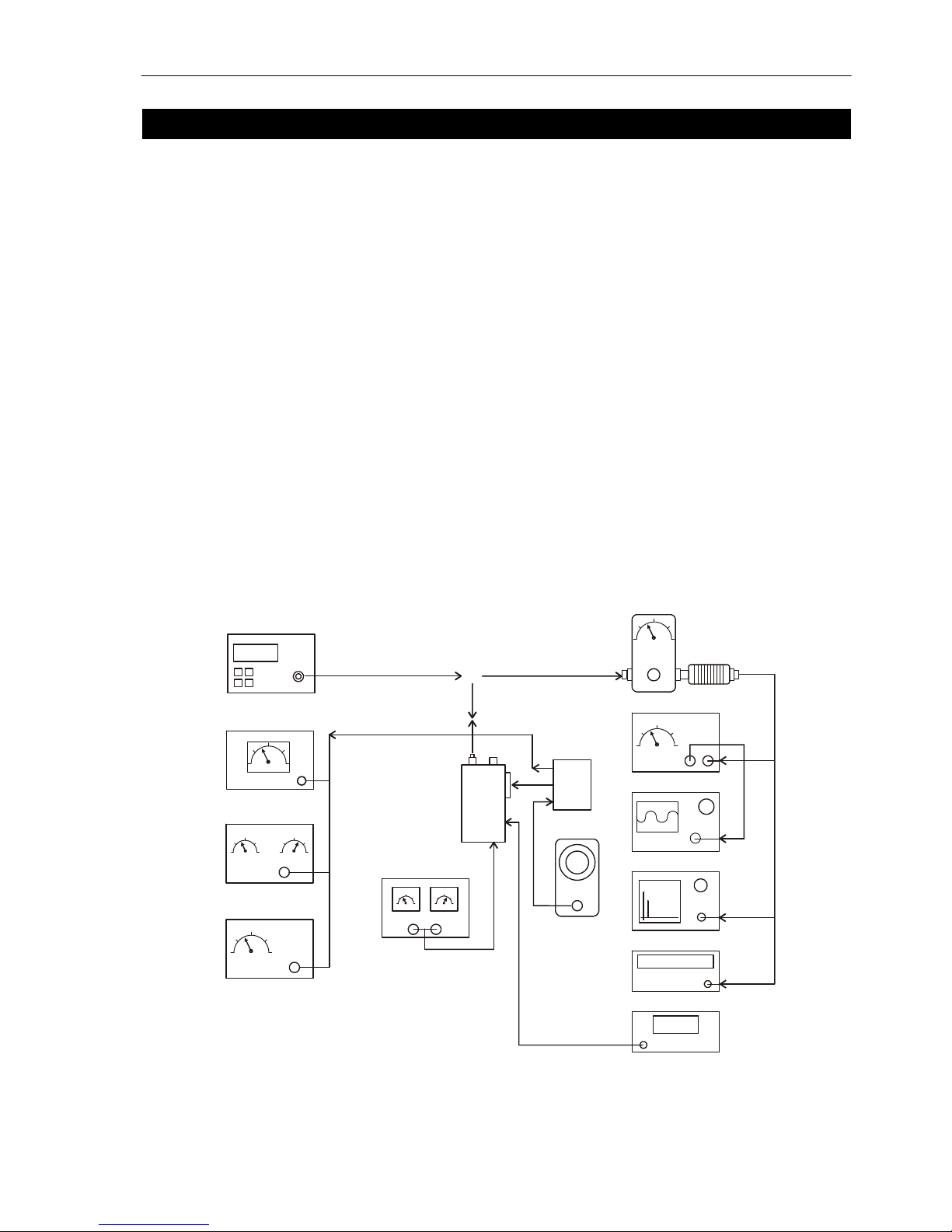
154.6254456
WATT METER WITH
20dB ATTENUATOR
AUDIO
MODULATION- METER
AUDIO GENERATOR
DC POWER SUPPLY
RADIO
OSCILLOSCOPE
SPECTRUM ANALYZER (optional)
FREQUENCY COUNTER
VOLT METER
AUDIO POWER METER
SINAD METER
DISTORTION METER
RF SIGNAL GENERATOR
3KHz Dev @ 1KHz (25 kHz Channel Spacing)
1.5KHz Dev @ 1KHz (12.5 kHz Channel Spacing)
TEST BOX
Figure 3-1 - Test Equipment Configuration

MaxonSM5102Radio
Prerequisites
For the following tests, signal generator
modulation level should be set to Average
System Deviation, i.e. 60% of maximum
system deviation.
The level should therefore be set to:
1.5 kHz for 12.5 kHz channel spacing
2.4 kHz for 20 kHz channel spacing
3.0 kHz for 25 kHz channel spacing
If the radio has had components installed to
change the channel spacing and/or operating
band from those installed at the factory,
ensure that the correct components are
installed in the receiver and transmitter
stages prior to testing.
Refer to the appropriate Electrical Parts List if
necessary.
EEPROM programming
Ensure that the EEPROM has the required
customer parameters programmed,
otherwise ensure that a test EEPROM is
programmed with at least the lowest, middle
and highest Rx/Tx frequencies prior to
aligning the VHF and UHF scanning
handheld series radio.
When CTCSS and DCS performance checks
are also required, ensure that the lowest,
middle and highest Rx/Tx frequencies
include:
Lowest Rx/Tx freq. ch. 67.0 Hz CTCSS
Middle Rx/Tx freq. ch. DCS Code 072
Highest Rx/Tx freq. ch. 250.3 Hz CTCSS
The middle Rx/Tx frequencies should be
halfway between the lowest and the highest
frequencies.
Programming details are given in Section 7.
2.1.1 Test Equipment Connection
Connect the power supply leads from the
battery eliminator to the power supply. The
red, positive, lead connects to +13.8Vdc.
The black, negative, lead connects to the
negative, terminal of the power supply.
2.1.2 Transmitter Performance Tests
Power Output
a. Connect the transmitter to the
Communications Test Set (CTS) with
the power meter set to read 50W.
b. Set the power supply to 13.8Vdc and
connect a dc voltmeter across the
power supply to monitor the supply
voltage.
c. Set the CTS to the same frequency as
the radio and PTT. Check and record
the power output. The nominal power
output is 5W for low power and 50W for
high power.
d. Reduce the power supply voltage to
11Vdc and PTT. The output power
should be greater than 65% of the level
measured above.
Frequency Error
a. Using the frequency counter check that
the transmit frequency is within
+/- 500Hz (VHF) or +/- 750Hz (UHF) of
the frequency which is programmed
into the radio.
Spot Deviation and Distortion
a. Set the radio to the middle Tx
frequency. Connect the oscilloscope to
the output of the modulation meter.
b. Set the audio signal generator to 1kHz
tone, low output impedance and
adjust its level for 60% system
deviation:
12.5kHz channel spacing 1.5kHz dev.
20kHz channel spacing 2.4kHz dev.
25kHz channel spacing 3kHz dev.
c. Press PTT.
d. Measure the audio distortion. This
should be less than 5%.
e. Increase the audio signal generator
level by 20dB (10x voltage). The peak
deviation should be:
12.5kHz channel spacing <= 2.25kHz dev.
20kHz channel spacing <= 3.6kHz dev.
25kHz channel spacing <= 4.5kHz dev.
f. Release PTT.

Maxon SM5102Radio
When CTCSS and DCS performance checks
are also required, ensure that the lowest,
middle and highest Rx/Tx frequencies
include:
Lowest Rx/Tx freq. ch. 67.0 Hz CTCSS
Middle Rx/Tx freq. ch. DCS Code 072
Highest Rx/Tx freq. ch. 250.3 Hz CTCSS
The middle Rx/Tx frequencies should be
halfway between the lowest and the highest
frequencies.
2.1.3 Receiver Performance Tests
Sensitivity
The SINAD performance test may be used to
test the sensitivity of the receiver.
a. Connect the RF signal generator,
modulated with a 1kHz tone, to the
radio.
b. Set the frequency to correspond to the
Rx frequency of one of the channels
programmed into the radio.
c. Connect the SINAD voltmeter to the
external speaker socket on the radio.
d. Press the monitor button and set the
volume control to mid-range.
e. Set the RF signal generator deviation
to:
12.5kHz channel spacing 1.5kHz dev.
20kHz channel spacing 2.4kHz dev.
25kHz channel spacing 3kHz dev.
f. Adjust the RF signal generator level
until the SINAD meter reads 12dB.
g. Check that the signal generator RF
level is < -117dBm (0.31µVpd).
Squelch
a. Ensure that both the radio and the
signal generator are set to the
appropriate channel spacing.
b. With the above setting, reduce the RF
level to –130dBm. The radio should be
mute. It may be necessary to press the
monitor button to achieve mute.
c. Adjust the RF level until the SINAD
meter reads 10dB. The radio should
unmute.
Audio Output
a. Set the RF signal generator to 1mV pd
(-47.0dBm) and the tone and deviation
as above.
b. Connect the audio power meter to the
external speaker socket on the
radio.
c. Adjust the volume control on the radio
under test to maximum (fully clockwise).
The voltmeter should indicate >= 3.5V.
The audio power meter should read
>= 3W.
Note: The audio power meter should be set
to 16Ω.
This concludes the Performance Tests.
If the Radio should fail any of these tests it
will be necessary to turn to the next section
on Alignment.
 Loading...