

Page 1
SD-270 Series Data Radio
User Manual
January 2017
Page 2

1
FCC RF Exposure Compliance Requirements
The Federal Communications Commission (FCC), with its action in General Docket
93-62, November 7, 1997, has adopted a safety standard for human expo su re to
Radio Frequency (RF) electromagnetic energy emitted by FCC regulated equipment.
Friendcom subscribes to the same safety standard for the use of its products. Proper
operation of this radio will result in user exposure far below the Occupational Sa fety
and Health (OSHA) and Federal Communications Commission limits.
About your SD-270 Series Data Radio
The SD-270 Series is a PLL synthesized 5-watt FM transceiver module, which is
designed for data transmission and voice communication. It can support
pre -emphasis, squelch CTCSS/DCS and audio amplifier. Two-point modulation
technology pro vi des a good low frequency response and POCSAG protocol is
optional. The radio has a fast start-up time, low power consumption, and the
optional modem boards from 1200-19200 bps add extra applications for its use. The
die cast aluminum cabinet and lid provides resistance to RF interference with the
most requested mechanical footprint in the industry.
Should you have questions regarding the operation of the radio, please consult us at:
Maxon America, Inc. Phone: 913-859-9515
11535 W. 83rd Terrace Email: maxon@maxonamerica.com
L e n e x a , KS 66214 Website: www.maxonamerica.com
Page 3

2
Features
C E , F C C , MRC & AS/NZS 4295: 2015 certified
Programmable 16 channels (Dip Switch Select)
External Software Channel Steering
Configurable Power Sa ve Fe at ure
FSK, 4FSK& GMSK Modem Options; Supports 19200 bps
Frequency Step 6.25KHz
CTCSS/DCS Encode/Decode
Fast start-up time: 5ms
SQ Programmable via PC (6 Levels)
POCSAG Modulation (Optional)
PC Programmable & Software Tune & Calibration
Applications
Industrial telemetry & wireless remote control or Paging system
Gas and oil flow monitoring
Electricity, water and gas utilities
Earthquake, weather, environmental protection
Vehicle tracking and asset tracking systems
Water monitoring, waste water management and irrigation control
Railway, police, army automation system
Aerial defense and fire alarm system
Urban lighting control
Page 4

3
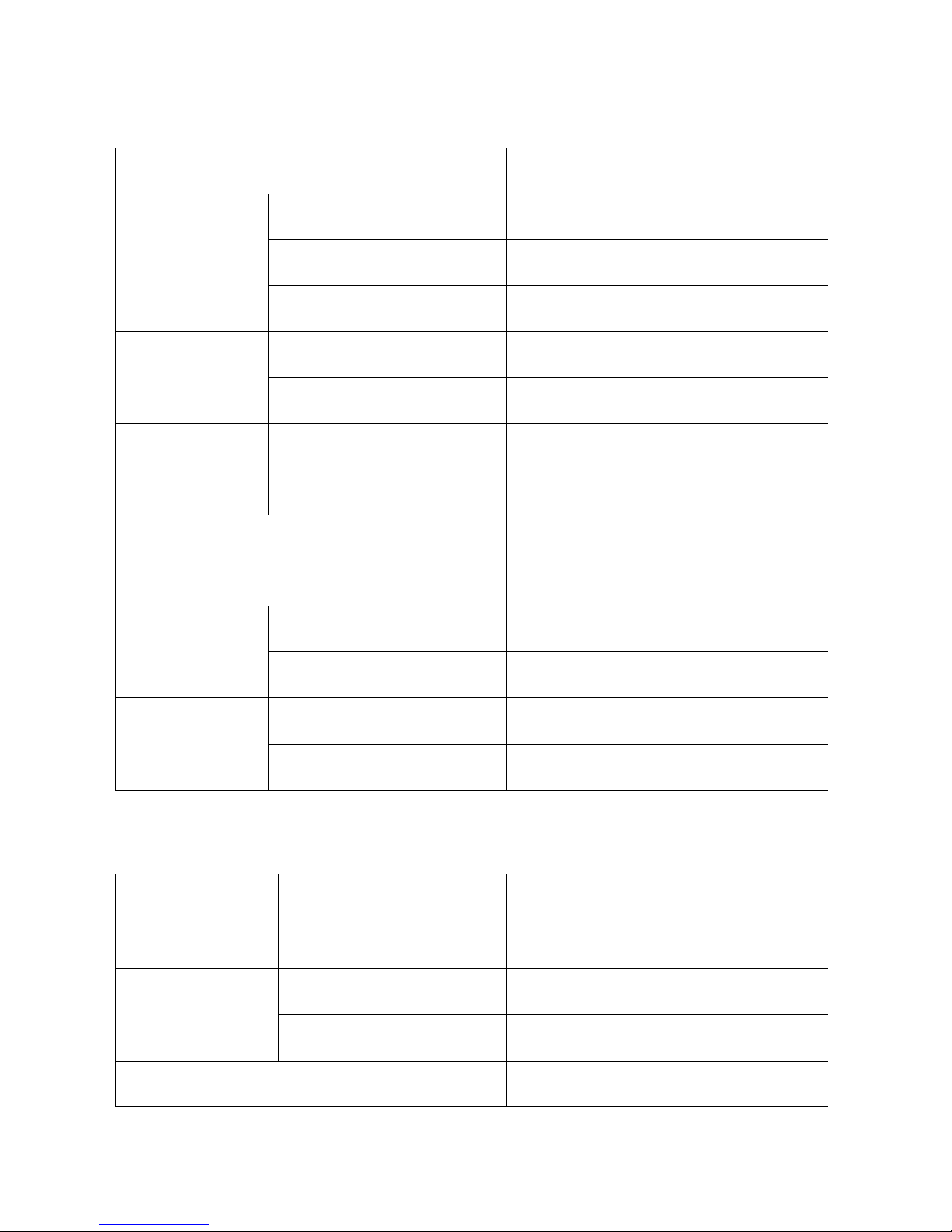
Specifications
GENERAL
Working Frequency
V: 136-174 MHz
U0: 400-440 MHz
U1: 430-470 MHz
U2: 450-490 MHz
Channel Spacing
12.5KHz/25KHz Programmable
Modulation Type
F3D/F3E
Number of Channels
16
Nominal Working Voltage
12V DC
Extreme Working Voltage
9.6 V~16V DC
Storage Temperature
-40℃~+80℃
Operating Temperature
-30℃~+65℃
Current
Consumption
Standby
<100mA (65 mA @ 12V)
Transmit 5 watts RF Power
<1.5A
Transmit 1 watt RF Power
<1A
TX to RX Attack Time
<5ms
RX to TX attack time
<5ms
Frequency Error
<2.5ppm
Antenna Connector
BNC 50Ω
External interface
DB15 Female
Page 5
4
TRANSMITTER Specification
R F P o w e r
1W/2W/3W/4W/5W Programmable
Frequency
Deviation
25KHz Channel Spacing
<5KHz
12.5KHz Channel Spacing
<2.5KHz
Subsonic
0.5KHz
Audio Response
25KHz Channel Spacing
300Hz~3KHz +1/-3dB
12.5KHz Channel Spacing
300Hz~2.55KHz +1/-3dB
Adjacent
Channel Power
25KHz Channel Spacing
<-70dBc
12.5KHz Channel Spacing
<-65dBc
Conducted Spurious Emission
<1GHz,<-36dBm
>1GHz,<-30dBm
Modulation
Sensitivity
V o i c e
8~15mV
Data
80~130mV
TX SNR
25KHz Channel Spacing
>45dB
12.5KHz Channel Spacing
>40dB
RECEIVER Specification
RX Sensitivity
(12dB SINAD)
25KHz Channel Spacing
<-119dBm Ex treme <-115dBm
12.5KHz Channel Spacing
<-119dBm Extreme<-115dBm
Adjacent Channel
Selectivity
25KHz Channel Spacing
>70dB
12.5KHz Channel Spacing
>60dB
Image Rejection
>70dB
Page 6

5
IF Rejection
>70dB
Spurious Rejection
>70dB
Intermodulation Suppression
>65dB
Conducted Spurious Emission
<-57dBm
Receiving Audio Distortion
<5%
RX SNR
25KHz Channel Spacing
>45dB
12.5KHz Channel Spacing
>40dB
Audio Output Power
0.5W @ 8Ωload
Exterior View
Description of radio components
① DB1 5 Fe ma le co nne ctor
② BNC Antenna connector
③ LED (Red for TX, Green for RX)
Page 7

6
SD-270 External DB15 female Pin Assignment
SD-270 Series is manufactured by default with modem , if the radio does not have a
built-in modem; the corresponding pin is defined as empty.
Pin
No.
Function
Description
Note
①
AUD IO_IN
(MOD IN)
Audio input, 3Khz LPF, Modulation
sensitivity is 100mV.
AUDIO _IN is effective only
when Pin7 (MIC) is vacant or
with +5V high level. 3KHz
LPF filter existed in audio
channel.
②
AUDIO _OUT
(AF OUT)
A u d i o o u t p u t , 3 K h z L P F . O u t p u t l e v e l a t
60% frequency deviation is 250±50mV.
This line has an internal pull-up resistor
t o + 5 V .
③
PTT
T X c o n t r o l , a c t i v e l o w , o n l y w h e n P T T i s
active AUD IO_IN and MIC IN are
effective. This line has an internal pullu p t o 5 V .
④
B+
(9.6~16V DC)
Positive pole input from DC p o w e r ,
nominal +12V.
⑤
P R OG
( D A T A O U T )
Programming data output, 5V TTL
⑥
BUSY
Logical level output to indicate
whether there is a carrier or not. Low
lever m ea n s carrier, high level means
no carrier. This line has a pull-u p to
+ 5 V .
⑦
MIC IN/RSSI
MIC IN: Microphone input.
RSSI: To detect the air signal strength.
Jumper selectable.
Can directly connect to
e l e c t r e t s M I C , t h e D C v o l t a g e
of this pin should lower than
3.5V, then MIC transmission
can be activated.
Page 8

7
⑧
P R OG
( D A T A I N )
Programming data input, 5V TTL
⑨
SPK/POCSAG
SPK: Audio output from the audio
amplifier, @ 8Ω.
POCSAG: To t ransmit POCSAG code.
Jumper selectable.
AUDIO_IN is effective only
when PIN7 (MIC) is vacant or
with +5V high level. 3KHz
LPF filter existed in audio
channel.
⑩
RXD
(MODEM)
The serial data is input to modem
through this pin. Default is RS232.
The hardware is one of
RS232, RS485 or TTL/5V
when delivery.
⑪
TXD
(MODEM)
Serial data is output from modem via
this pin. Default is RS232.
The hardware is one of
RS232, RS485 or TTL/5V
when delivery.
⑫
CD_OUT
(MODEM)
Logical level output to indicated
whether a carrier or not. Low lever for
carrier, high level for no carrier.
⑬
NC
No connection
⑭
GND
Ground
⑮
NC
No connection
Antenna installation
Fasten the antenna to the radio by turning the antenna connector clockwise into the
receptacle on right of radio when looking at front of radio.
Powering the Data Radio
SD-270 accepts variable s o u r c e s o f D C p o w e r t o p e r m i t m o r e v e r s a t i l e u s e . T h i s r a d i o
o p er a te s f ro m 9. 6V to 16 V D C an d s ta n da rd vo l ta ge fo r te s ting i s 1 2V D C . T he 4th pin
of DB15 female connector is the power input pin.
SD-270 Series Function
Channel Spacing
The radio is capable of programmable channel spacing, having 12.5KHz or 25KHz
channel spacing.
Page 9

8
SQ (S qu elch) L eve l
Six SQ l e ve ls are set in the radio and can be selected by PC software.
The audio signal will continuously transmit. Levels are shown as below:
Level 0 is for fully open mute.
Level 1:0.15uV
Level 2:0.25uV
Level 3:0.35uV
Level 4:0.45uV
Level 5:0.55uV
CTCSS/DCS
To help block out unwanted calls to your radio, the SD-270 can be programmed to
set CTCSS/DCS code. When enabled, receiver can only receive RF signal with the
same CTCSS/DCS code of the transmitter to avoid interference from unwanted
signals. For fast lock times, the CTCSS/DCS is not recommended for high speed data
transmission.
Channel Scan
The radio enables to detect the channels by initiate scanning mode. Scanning mode
is optional and programmable. Four scan modes are provided as shown below:
0 ---------normal scan with carry only
1 ---------normal scan, Carry with tone
2 ---------priority scan, Carry only
Page 10
9
3 ---------priority scan, carry with tone
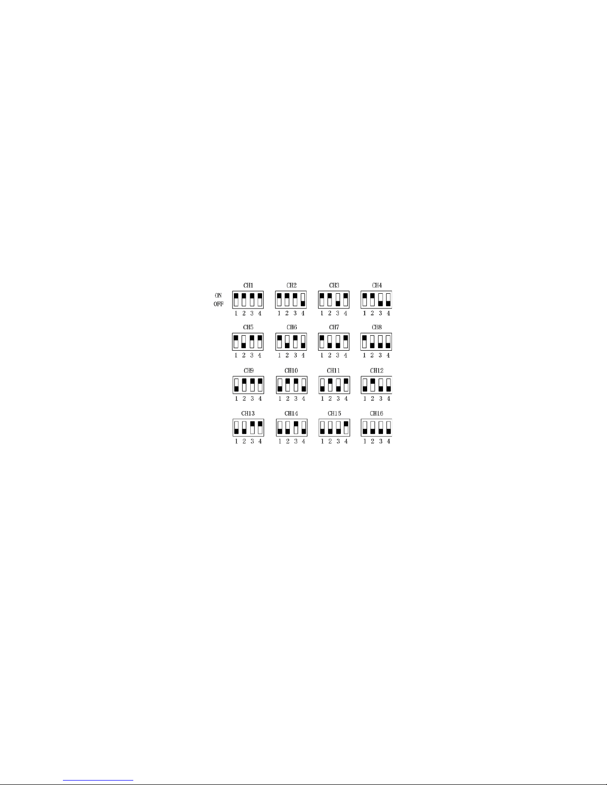
Channel Select
16 channels can be selected by inner dip (4) sw itch (HW) on power board or serial
command inputted from our PC s o f t w a r e ( SW). Only in SW control mode, channel
can be selected by PC software in “Channel” feature.
Channel Dip Sw i t c h Chart
TX Protection
This feature, when enabled, limits the amount of time that the radio can
continuously transmit for p r o t e c t ing the radio from block of the channel and
damage on radio which is caused by sustained transmission. In TX mode, if PTT is
effective all through and exceed set time, radio will stop transmitting automatically
until restart the PPT again. The time is set by programming.
V o l u m e
The radio output voice via SPK Pin with 10 vo lume levels. The choice of appropriate
Page 11

10
volume for the connected speaker in set in the programming. The default volume is
6. The minimal volume is 0 and the maximum is 9.
P o w e r Save Mode
When user enables the function, The SD-270 will operate in a status to lower power
consumption in standby. If a useful signal is detected, the radio will begin to receive
normally. If no useful signal detected, the radio will revert to power save. Power save
in t e r v a l s can be set in the programming. Not recommended when using for data
transmission.
Side Tone
This feature, when enabled, transmits the MIC signal via the ou t pu t f ro m S PK p o r t to
allow user to h e a r h i s o r h e r o w n v o i c e . T h e f e a t u r e c a n a l s o b e s e t v i a programming.
RSSI Detection
In TX mode, the radio can quickly detect the strength of a useful RF signal and
indicate the strength by analog voltage after calculation and analysis of MCU.
Stronger signal means higher output voltage. The field strength can also be viewed
by serial command.
L E D S t a t us Indicator
The LED indicator gives real time status of the radio's operation, R e d f o r T X and
gre en f or R X.
Page 12

11
Parameter Programming
The SD-274 is configured before leave factory, the user can directly use. If the
parameters of the radio need to be modified, refer to the pro gra mmi ng sof tware and
manual.
Modem Option for Data Communication
DTE: Data Terminal Equipment
Available Baud rate for FSK modem
Channel Space
DTE Baud Rate(bps)
Modem Baud Rate(bps)
Narrow (12.5KHz)
1200
1200
Wide (25KHz )
1200
1200
Available Baud rate for GMSK modem
Channel Space
DTE Baud Rate(bps)
Modem Baud Rate(bps)
Narrow (12.5KHz)
9600
9600
Wide (25KHz)
9600
9600
Available Baud rate for 4FSK modem
Channel Space
DTE Baud Rate (bps)
Modem Baud Rate (bps)
Narrow (12.5KHz)
9600
9600
Wide (25KHz)
9600 or 19200
9600 or 19200
Communication Between DTE and Modem
The internal option-modems (FSK, GMSK, 4FSK) are applied to the SD-270 t o
increase capability for data applications. The goal of an internal modem is to
Page 13
12
improve the efficiency for data transmission and provide maximum flexibility for user
applications. The internal modem options consist of MCU, Modem IC, and extra
circuitry. These option-boards directly communicate with DTE to send and receive
meaningful data through the DB15 female connector. These modems are designed
to accept RS232, RSTTL or RS485 serial data format and are also capable of high
speed wireless data-transmission between two or more devices.
A T Command of Modem (Only f o r GMSK or 4FSK)
Mode
Command
Return
Remark
Querying radio channel
AT+CHN=?\r
\r\nCHN=N\r\n
The range of N is from 1 to 16,
means channel number.
Setting channel
AT+CHN=N\r
\r\nOK\r\n or \r\nERROR\r\n
Querying baud rate
AT+WORKMODE=?\r
\r\nWORKMODE=N\r\n
N is M9600 or M19200,
M9600 means 9600bps…
Setting baud rate
AT+WORKMODE=N\r
\r\nOK\r\n or \r\nERROR\r\n
\r s t a n d f o r carriage r e t u r n (ASCII is 0XO D )
\n s t a n d f o r line f e e d (AS CII i s 0X0A)
Only 4FSK modem can be set to 19200bps.
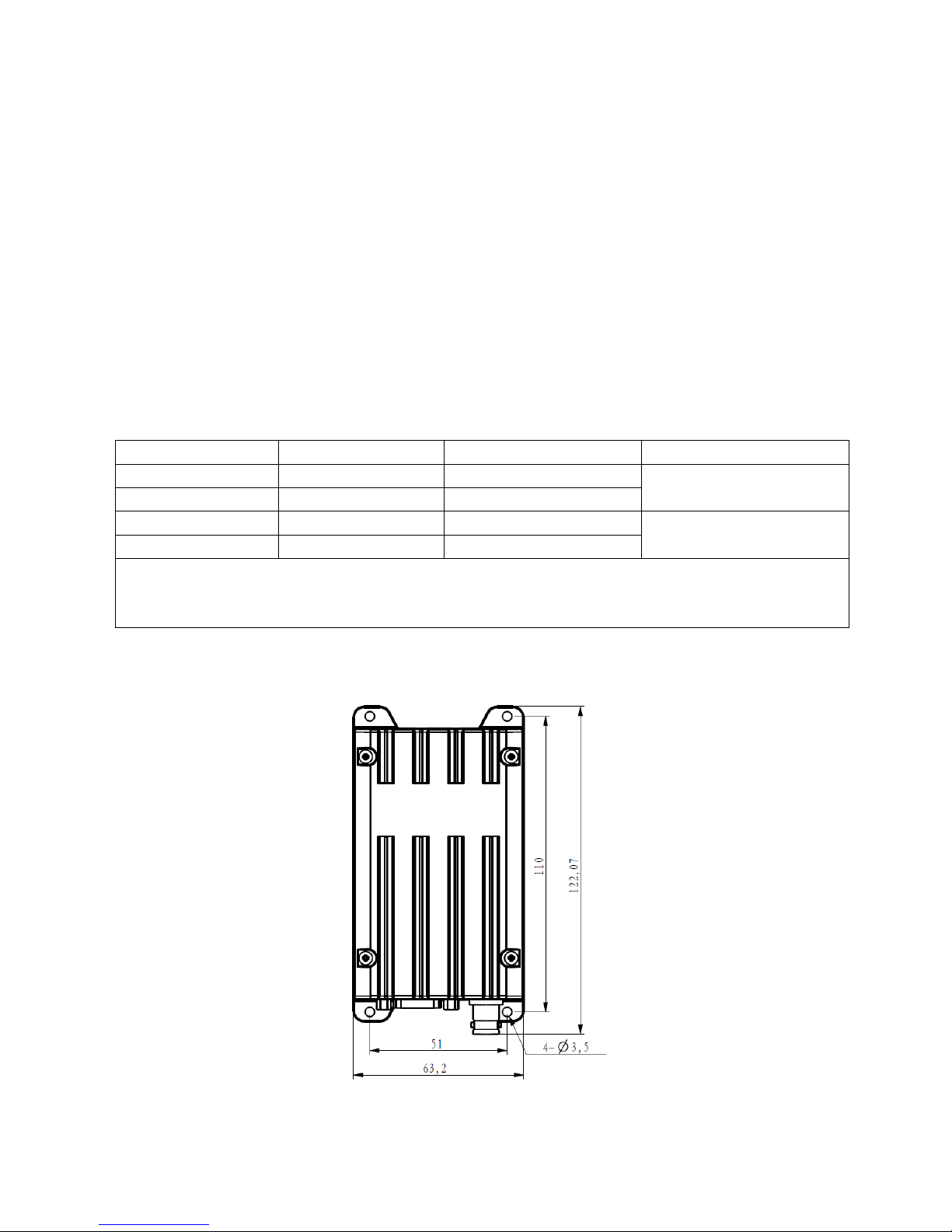
Dimensions
Page 14

13
 Loading...