

Maxon SD170EX, SD171EX, SD174EX Service Manual

Service Manual SD170EX Series
Amendment Record Sheet
All amendments to this manual should be incorporated as soon as they are received and
recorded below:
Issue No. Effective
Date
Reason for Change Date Signature
All Engineering Bulletins relevant to this product should be placed at the rear of this binder.
Please ensure that this manual is updated with any replacement pages, which may accompany
these Engineering Bulletins.
Always read all Engineering Bulletins before carrying out work on a radio.
Please read the WARNINGS on the next page before referring to subsequent sections.
Page 2 of 38
A
A
A
m
m
m
e
e
e
n
n
n
d
d
d
m
m
m
e
e
e
n
n
n
t
t
t
s
s
s

Service Manual SD170EX Series
Warnings
1. WARNING! NEVER connect the transceiver to an AC outlet. This may pose a fire hazard
or result in an electric shock.
2. NEVER operate the radio transmitter without a suitable artificial load or antenna
connected.
3. NEVER connect the transceiver to a power source of more than 13.8V.
4. NEVER dispose of the battery in fire – it can explode causing personal injury.
5. NEVER attempt to disassemble the battery or remove its case material or charging
contacts. Do not short the battery terminals.
6. NEVER expose the transceiver to rain, snow or any liquids.
7. NEVER modify a radio or accessory except as instructed in the service manual,
engineering bulletins or formal communication as this may invalidate any warranty,
guarantee or type approval.
8. USE the supplied microphone only. Other microphones have different pin assignments
and may damage the transceiver.
9. DO NOT use or place the transceiver in areas with temperatures below -30°C or above
+60°C, In areas subject to direct sunlight, such as the dashboard.
10. DO NOT hold the radio in such a manner that the antenna is next to, or touching,
exposed parts of the body, especially the face or eyes, while transmitting.
11. DO NOT allow children to operate transmitter-equipped radio equipment.
12. DO NOT operate the radio near unshielded electrical blasting caps or in an explosive
atmosphere, unless it is a type especially designed and qualified for such use.
13. NEVER modify this device or its accessories, except as instructed in the Service Manual,
Engineering Bulletins or formal communication as this may invalidate any warranty,
guarantee or type approval.
14. AVOID placing the transceiver in excessively dusty environments.
W
W
W
a
a
a
r
r
r
n
n
n
i
i
i
n
n
n
g
g
g
s
s
s
Page 3 of 38

Service Manual SD170EX Series
Contents
Amendment Record Sheet............................................................................................................ 2
Warnings ..................................................................................................................................... 3
Contents ...................................................................................................................................... 4
Introduction ................................................................................................................................. 5
Pre-Install check, Accessories & Options ...................................................................................... 6
Pre-Installation ......................................................................................................................... 6
Accessories ............................................................................................................................. 6
etc ........................................................................................................................................... 6
Product Introduction .................................................................................................................... 7
Installation ................................................................................................................................... 8
Installation ............................................................................................................................... 8
External Connections ............................................................................................................... 8
General Specification.................................................................................................................... 9
Transmitter Specification ............................................................................................................ 10
Receiver Specification ................................................................................................................ 11
Reference Crystal ....................................................................................................................... 12
Enviromental.............................................................................................................................. 12
Dimensions ................................................................................................................................ 12
Features .................................................................................................................................... 13
Access to digital and RF boards .................................................................................................. 16
Alignment .................................................................................................................................. 19
Alignment points ........................................................................................................................ 23
Flow Diagrams ........................................................................................................................... 24
CTCSS ....................................................................................................................................... 26
Interfacing ................................................................................................................................. 27
External connections .............................................................................................................. 27
DB-9 PIN descriptions with input/output level.......................................................................... 27
Channel Selection ...................................................................................................................... 29
SD170EX Layouts Control Board ................................................................................................. 30
SD171EX Layouts RF Board ........................................................................................................ 34
SD174EX Layouts RF Board ........................................................................................................ 34
SD170EX control schematic ...................................................................................................... 34
SD171EX RF schematic ............................................................................................................ 34
SD174EX RX schematic ............................................................................................................ 34
C
C
C
o
o
o
n
n
n
t
t
t
e
e
e
n
n
n
t
t
t
s
s
s
Page 4 of 38

Service Manual SD170EX Series
Introduction
This Maxon Product Manual is a comprehensive guide to the maintenance and field repair of this
equipment. It covers all versions of the SD170EX Series data radio(s). Before using this manual
please read the whole of this introductory chapter, this will help you to make the best use of it. If
you have not done so already, please also read the warnings immediately in front of this chapter
before proceeding any further.
Using this Manual
The organization of this manual has been arranged to enable the location and referencing of
information, as quickly as possible.
Section 3 - Installation, Commissioning & Alignment. Describes connections to the radio, how to
commission it and how to align the radio should this becomes necessary.
Section 4 - Detailed functional description.
Section 5 - Troubleshooting.
Amendments to this Manual
From time to time during its lifetime, this product will be updated and improved. To cover such
changes, amendments to this manual will be issued in the form of replacements and/or additional
pages. It is important that anyone working on a product has all the relevant information. Therefore
you should incorporate amendments to this manual on receipt. Please follow the instructions
accompanying the amendment (in the form of an Engineering Bulletin) and be sure to complete
the amendment record at the front of this manual.
On occasion it may be necessary to issue product information more quickly than can be achieved
with an amendment. In this case the information will be distributed as a Maxon Engineering
Bulletin. Engineering Bulletin numbers are prefixed with a category letter – A, B or C.
E.g. CATEGORY C – ENGINEERING BULLETIN 120
Category C describes how Maxon recommends an improvement and/or a modification to make an
improvement to a product
Engineering Bulletin 120 index number allocated to this bulletin.
‘A’ Category A Engineering Bulletins will only be released if, by using the equipment
manufactured by Maxon or its subcontractors, a risk to operator safety or an infringement of Type
Approval is probable.
All units affected should be returned for modification to Maxon CIC Europe Works Department on
receipt of such a Bulletin.
Page 5 of 38
I
I
I
n
n
n
t
t
t
r
r
r
o
o
o
d
d
d
u
u
u
c
c
c
t
t
t
i
i
i
o
o
o
n
n
n

Service Manual SD170EX Series
‘B’ Category B Engineering Bulletins are for equipment manufactured by Maxon CIC that may
have component batch problems.
All equipment affected that is in service must be returned to the Distributor or Dealer workshop for
modification. Maxon CIC will supply replacement components free of charge.
‘C’ Category C Engineering Bulletins are for improvement or modification to equipment
manufactured by Maxon.
Dealer / Distributor to modify affected units in the field on the next service call. Maxon will supply
components free of charge.
Please place these at the back of this manual and refer to them before carrying out any work. This
Service Manual should be updated with any accompanying replacement pages. You may wish to
retain the previous issue pages for future reference.
Pre-Install check, Accessories & Options
Pre-Installation
As standard the SD-170EX Series Radio Modem is supplied with fused power Cable and
manual.
Accessories
The following Accessories are available:
Order Code Description
Antennas
CA1506-MB VHF Helical Antenna 148 - 160MHz
CA1506-HB VHF Helical Antenna 160 - 174MHz
CA4502 UHF Quarter-wave Whip Antenna 420 – 470MHz
Programmer
ACC-916 SD-170EX Series Programming kit Allows frequencies and
features to be changed.
Programming lead
Service
ACC-516E Extender PCB Allows RF PCB to be spaced off of the Digital
PCB to facilitate Alignment procedures.
V2 142-174MHz
U2 450-490MHz.
12.5 KHz or 25 KHz versions of all bands.
Page 6 of 38
I
I
I
n
n
n
t
t
t
r
r
r
o
o
o
d
d
d
u
u
u
c
c
c
t
t
t
i
i
i
o
o
o
n
n
n
Service Manual SD170EX Series
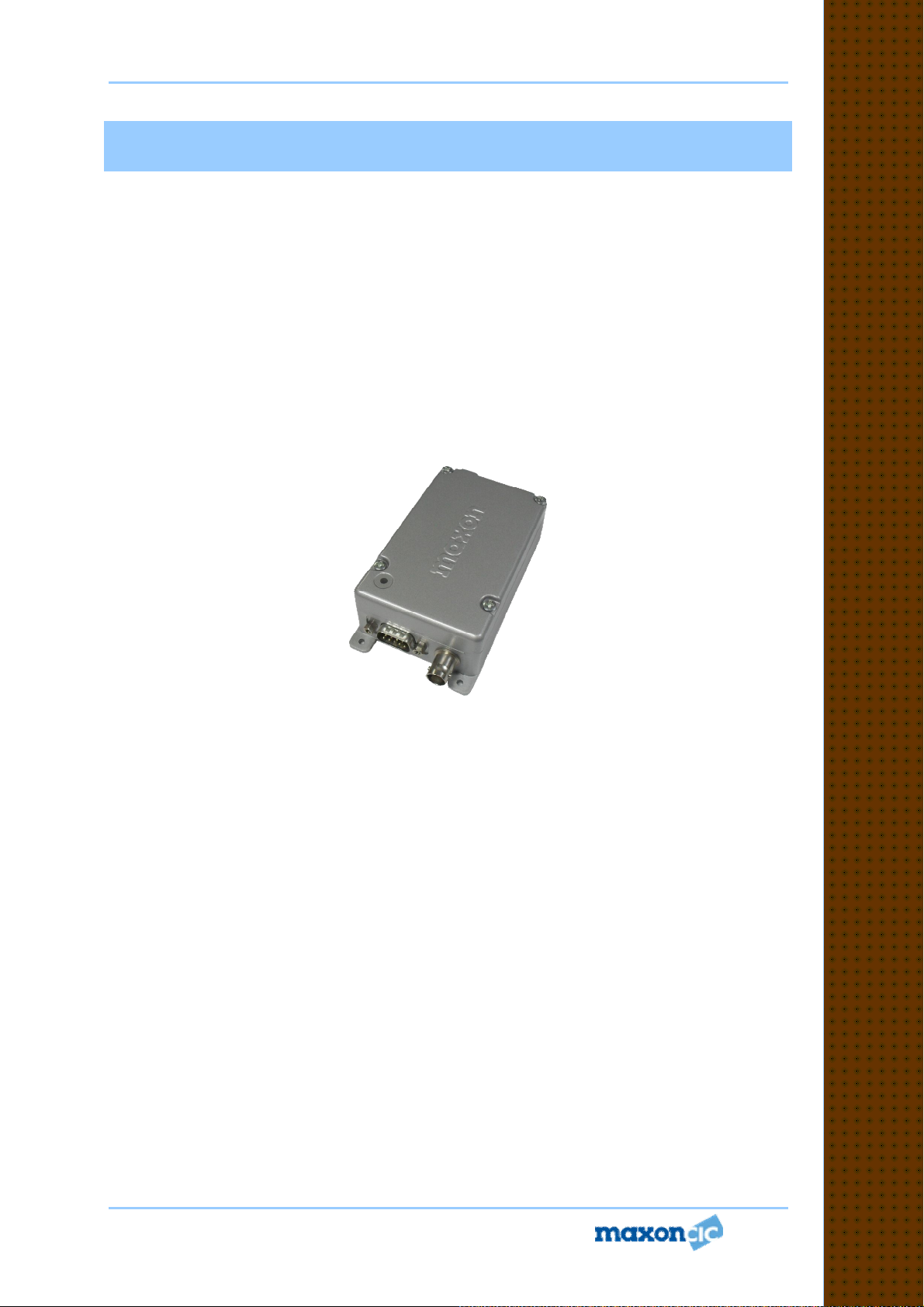
Product Introduction
The SD-170EX Series (here in after called “the radios”) of RF wireless modems from MAXONCIC
utilize the latest technology in its design and manufacturing. Both the UHF and VHF models are
Phase Lock Loop Synthesizer (PLL) / microprocessor controlled and offer five watts of power with
16-channel capability. Programmable sub-audio squelch system (CTCSS & DCS) and two-tone
squelch system are newly added to the signal level detect squelch system (RSSI) through PC
Program. The radios are programmed using ACC 916 programming software, an Intel Pentium2
or higher Personal Computer, Operating system is Microsoft windows 98, ME, 2000, and XP and
Vista based software, an interface module and a programming cable. This allows the radio to be
tailored to meet the requirements of the individual user and of the System(s) it is operating within.
Antenna / RF connector
Programmer ACC 916
Page 7 of 38
BNC type nominal 50 impedance
XP, Vista, ME, 2000 and Windows based programmer
allowing personalization of the SD-170EX Series
Modems via the RS232 port.
P
P
P
r
r
r
o
o
o
d
d
d
u
u
u
c
c
c
t
t
t
I
I
I
n
n
n
t
t
t
r
r
r
o
o
o
d
d
d
u
u
u
c
c
c
t
t
t
i
i
i
o
o
o
n
n
n
Service Manual SD170EX Series
Installation
Installation
The SD-170EX Series Radio Modems usually requires mounting in a suitable location.
Attention should be given to the heat sinking of the radio if prolonged transmission is
required; see Section 2, which also includes details of the mounting hole dimensions.
Note: Continuous transmission is not possible at high power (5W) without a suitable heat
sink.
The SD-170EX Series Radio Modems can be used with helical or whip aerials or may be
connected to an external antenna, via a suitable connecting cable.
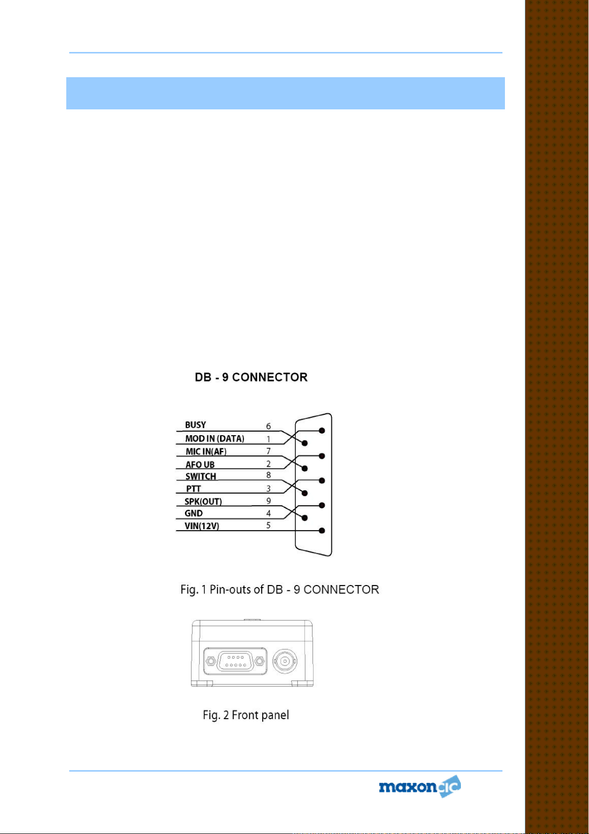
External Connections
Connection is made to the SD-170EX Series Radio Modems via an external 50 ohm BNC
socket (RF signal) and a high density 9-way “D”-type socket (DB-9 connector; control and
data signals) with 4-40 UNC threaded jack posts for more permanent connection. Besides,
SCN-12 type circular connector is added to separate power line from data and analogue
signals of DB-9 connector.
Page 8 of 38
Service Manual SD170EX Series
VHF
UHF
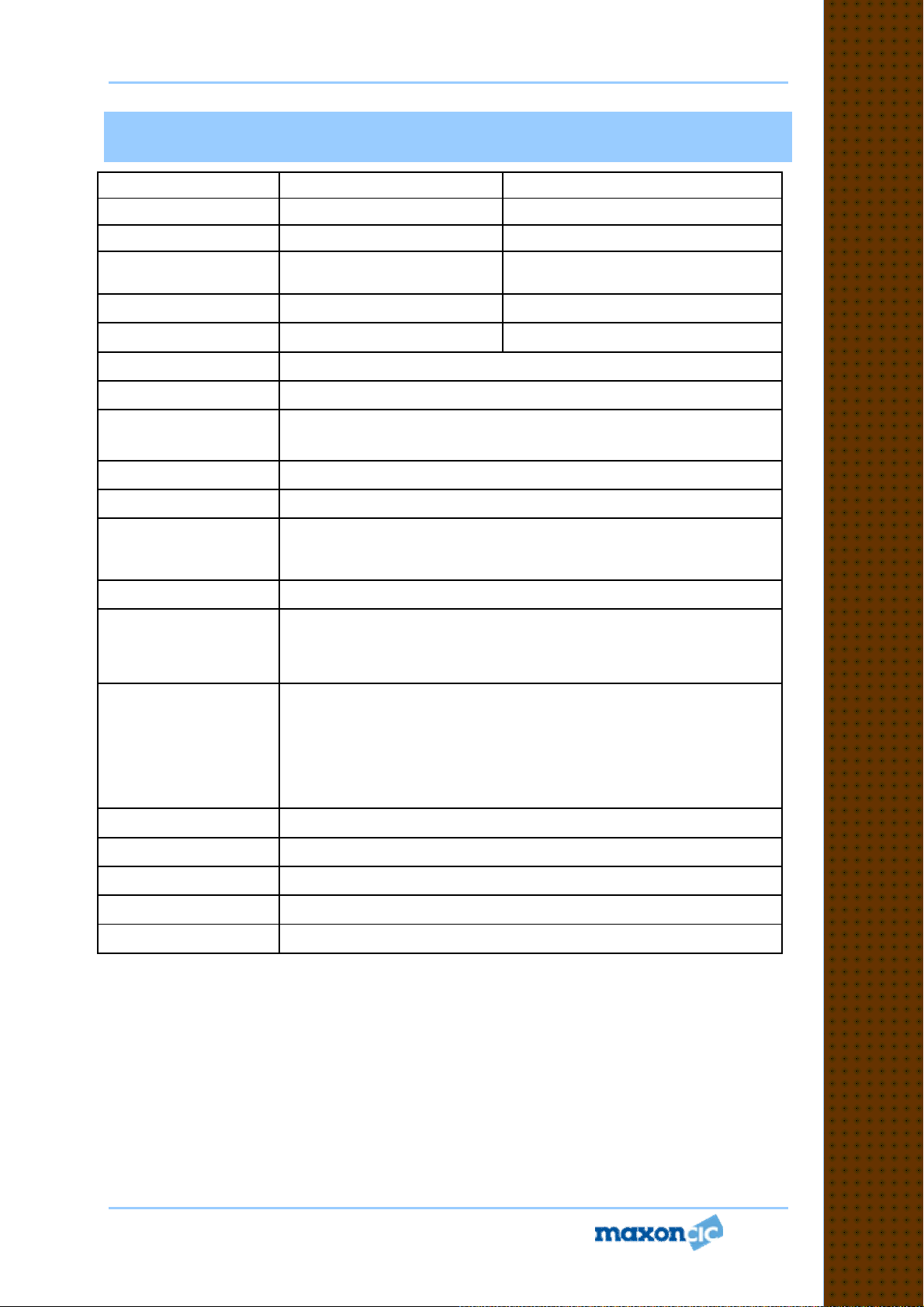
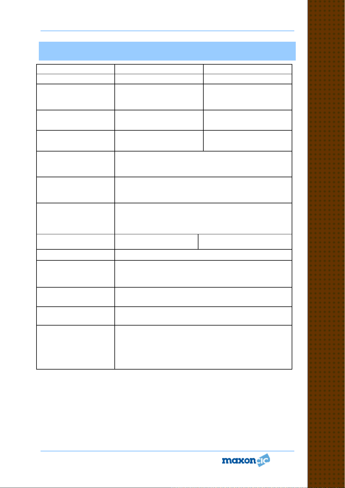
General Specification
Equipment Type
Model Series
Performance
Specifications
Frequency Range
RF Output
Channel Spacing
Modulation Type
Intermediate
Frequency
Number of Channels
Frequency Source
Operation Rating
Power Supply
Temperature Range
Storage
Operating
Data radio (Wireless Modem)
SD-171EX SD-174EX
TIA/EIA-603 /ETS 300-113 TIA/EIA-603 /ETS 300-113
142-174MHz 450-490MHz
1-5W 1-5W
12.5KHz, 25KHz Programmable
45.1MHz & 455KHz
Synthesizer
Intermittent
90 : 5 : 5 (Standby : RX : TX)
Ext. Power Supply (12 VDC Nominal)
From -40°C to +80°C
From -30°C to +60°C
Data radio (Wireless Modem)
F3D, F3E
16
Current Consumption
Standby(Muted)
Transmit 5Watts RF
Power
Transmit 2Watts RF
Power
Lock Time
TX to RX attack time
RX to TX attack time
Dimensions
Weight
Page 9 of 38
< 65mA
< 2.0 A
< 1.0 A
< 10ms
< 20ms (No Power Saving)
< 20ms
(118mm)W X (63mm)H X (35mm)D
266.5grams
G
G
G
e
e
e
n
n
n
e
e
e
r
r
r
a
a
a
l
l
l
S
S
S
p
p
p
e
e
e
c
c
c
i
i
i
f
f
f
i
i
i
c
c
c
a
a
a
t
t
t
i
i
i
o
o
o
n
n
n
Service Manual SD170EX Series
VHF
UHF
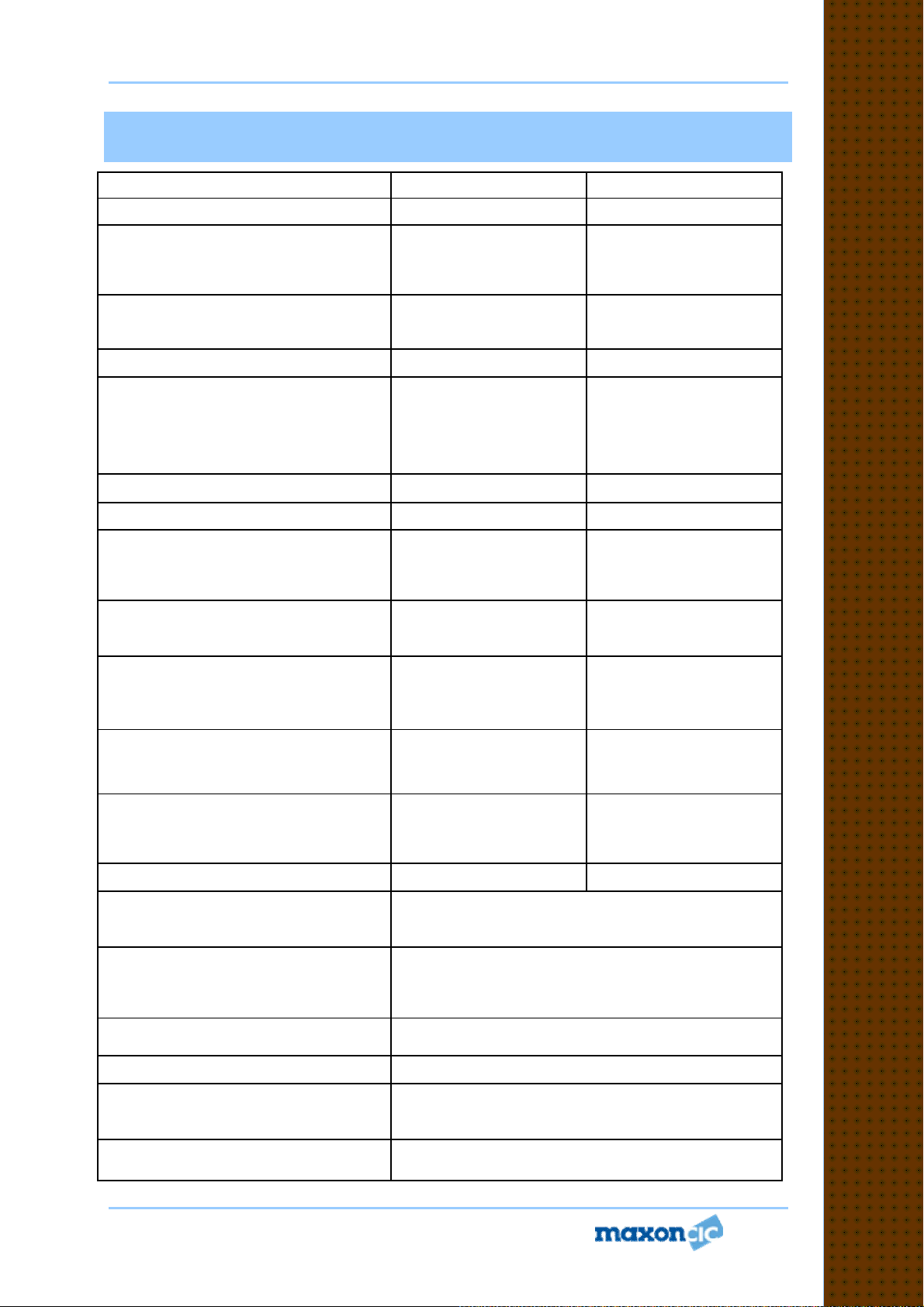
Carrier
Power (
Nom. Max.
Low Power
Sustained Transmission
(Nominal Conditions)
Frequency Error
Transmitter Specification
Model Series
Min.)
Hi Power
Time : 5 10 30 Sec
Nominal condition
Extreme condition
Frequency Deviation
25 KHz Channel Spacing
12.5 KHz Channel Spacing
Audio Frequency
Response
Adjacent Channel Power
25 KHz Channel Spacing
12.5 KHz Channel Spacing
Conducted Spurious
Emission
Modulation Sensitivity
Hum & Noise
25 KHz Channel Spacing
12.5 KHz Channel Spacing
SD-171EX SD-174EX
5W < 6W > 4.5W
1W<1.5W>0.8W
Power : >90% >85% >80%
< 0.5 KHz ±2.5 ppm
Peak ±5.0, Min. ±3.8KHz
Peak ±2.5, Min. ±1.9KHz
Within +1/-3dB of 6dB octave
@ 300 Hz to 2.55 kHz for 12.5 kHz C.S.
@ 300 Hz to 3.0 kHz for 25 kHz C.S.
< 70 dBc @ Nominal Condition , < 65 dBc @ Extreme Condition
< 60 dBc @ Nominal Condition , < 55 dBc @ Extreme Condition
< -36 dBm < -36 dBm
100mV RMS @ 60% Peak Dev.
> 40 dB (without PSOPH)
> 40 dB (with PSOPH)
5W < 6W > 4.5W
1W<1.5W>0.8W
Power : >90% >85% >80%
< 0.75 KHz ±2.5 ppm
Modulation Symmetry
Load Stability
Peak Deviation Range
Adjustment
@ 1 KHz, Nom Dev +
20dB :
25 KHz Channel Spacing
12.5 KHz Channel Spacing
Page 10 of 38
< 10% Peak Dev @ 1KHz input for nominal dev. + 20dB
No osc at ≥ 10:1 VSWR all phase angles and suitable antenna
No destroy at ≥ 20:1 all phase angle
Min. 3.5, Max. 6.0
Min. 1.5, Max. 4.0
T
T
T
r
r
r
a
a
a
n
n
n
s
s
s
m
m
m
i
i
i
t
t
t
t
t
t
e
e
e
r
r
r
S
S
S
p
p
p
e
e
e
c
c
c
i
i
i
f
f
f
i
i
i
c
c
c
a
a
a
t
t
t
i
i
i
o
o
o
n
n
n
Service Manual SD170EX Series
VHF
UHF
Sensitivity (
1/100 Error Rate
)
With ACC
-
514
< -110dBm
< -110dBm
Conducted Spurious Emission
Receiver Specification
Model Series
Sensitivity (@ 12dB SINAD)
25 KHz Channel Spacing
12.5 KHz Channel Spacing
With ACC-513
Amplitude Characteristic > -3dB , < +3dB > -3dB , < +3dB
Adjacent Channel Selectivity
25 KHz Channel Spacing(Nom.)
(Extreme Condition)
12.5 KHz Channel Spacing(Nom.)
(Extreme Condition)
Spurious Rejection(100KHz ~ 4GHz) > 70 dB > 70 dB
Image / Half IF Rejection > 70 dB > 70 dB
Intermodulation Response Rejection
±25 kHz/ 50 kHz
±50 kHz/ 100 kHz
9 KHz - 1 GHz
1 GHz – 4 GHz
SD-171EX SD-174EX
< 0.28uV
< 0.30uV
< -113dBm
> 70 dB
> 60 dB
> 65 dB
> 50 dB
> 70 dB
> 70 dB
< - 57 dBm
< - 47 dBm
< 0.28uV
< 0.30uV
< -113dBm
> 70 dB
> 60 dB
> 65 dB
> 50 dB
> 70 dB
> 70 dB
< - 57 dBm
< - 47 dBm
RX Spurious Emissions (Radiated)
9 KHz - 1 GHz
1 GHz – 4 GHz
AF Distortion :
Nominal condition
Extreme condition
RX Hum & Noise (only audio)
25 KHz Channel Spacing
12.5 KHz Channel Spacing
Receiver Response Time
Squelch (factory pre-set)
Open
Close
Squelch Attack Time :
RF Level at Threshold
RF Level at Threshold + 20dB
Squelch Decay Time
Antenna Socket Input Match
Temperature Stability for
L.O. Frequency
L.O. Frequency Aging Rate
Page 11 of 38
< - 57 dBm
< - 47 dBm
< 3%
< 10%
< 40 dB without PSOPH
< 16 ms < 16 ms
-113dBm
-116dBm
< 20 ms (RSSI), < 40 ms (Analog)
< 10 ms (RSSI), < 30 ms (Analog)
5 ms Min., 20ms Max.
> 10 dB Return Loss
1st < 5 ppm, 2nd < 15 ppm from -30° to + 60° C
±2 ppm/ year
< 40 dB with PSOPH
< - 57 dBm
< - 47 dBm
< 3%
< 10%
R
R
R
e
e
e
c
c
c
e
e
e
i
i
i
v
v
v
e
e
e
r
r
r
S
S
S
p
p
p
e
e
e
c
c
c
i
i
i
f
f
f
i
i
i
c
c
c
a
a
a
t
t
t
i
i
i
o
o
o
n
n
n
Service Manual SD170EX Series
Temperature
Model Series :
Temperature (deg C)
Reference Crystal
Model Series
Frequency
Type
Characteristic
Aging Rate
Enviromental
Operating
Storage
ESD
Due to continuing research and development the company reserves the right to alter
these specifications without prior notice.
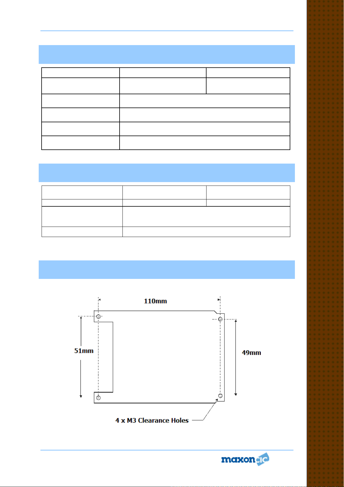
Dimensions
Dimensions: 122mm (L) x 62mm (W) x 35mm (D)
-30° to +60° C Degradation Specified @ Extreme condition
VHF UHF
SD-171EX
12.8MHz
DV-5-2.5H1
±2.5 ppm from -30° C to +60° C
< 2 ppm/ year in 1st year
< 1 ppm/ year thereafter
VHF
SD-171EX SD-174EX
-40° to +80° C
20 KV
SD-174EX
UHF
R
R
R
e
e
e
f
f
f
e
e
e
r
r
r
e
e
e
n
n
n
c
c
c
e
e
e
X
X
X
t
t
t
a
a
a
l
l
l
,
,
,
D
D
D
i
i
i
m
m
m
Page 12 of 38
Fig 3. Dimensions
e
e
e
n
n
n
s
s
s
i
i
i
o
o
o
n
n
n
S
S
S
p
p
p
e
e
e
c
c
c
i
i
i
f
f
f
i
i
i
c
c
c
a
a
a
t
t
t
i
i
i
o
o
o
n
n
n
 Loading...