

Maxon SD-171E, SD-174E Instruction Manual
SD-171E / SD-174E
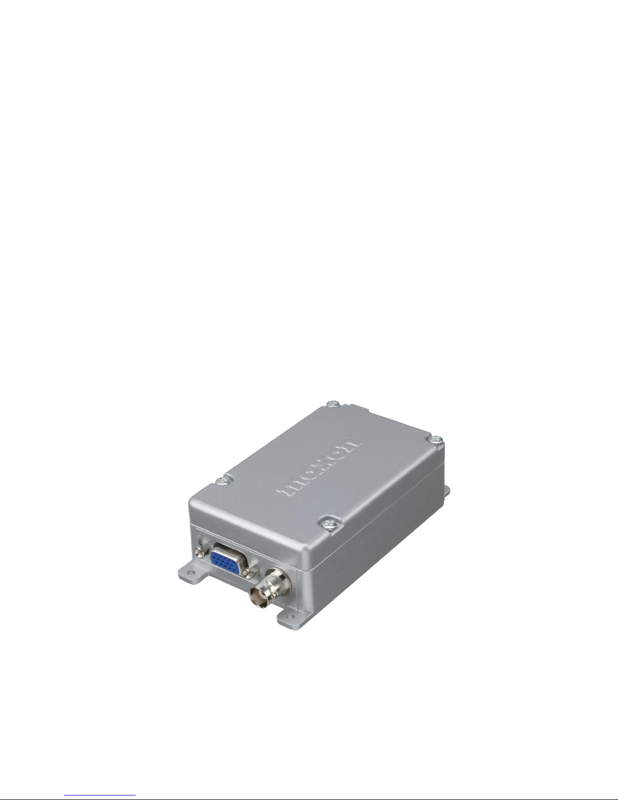
Data Radio
User Instruction Manual

2
About your SD-170E Series Data Radio
The SD-170E Series of RF Link Modules utilize the latest technology in their designs and manufacturing. SD-170E models
are Phase Lock Loop Synthesizer (PLL) / microprocessor controlled and offers 1/ 5 watt (Low / High) programmable output
power with 16-channel capability. Multiple functions including 1200 to 9600 baud rates, AC and/or DC audio coupling,
GMSK, FFSK and FSK modulation are standard in these fully programmable RF Link Module units. Programmable sub-
audio squelch system (CTCSS & DCS) and two-tone squelch system are added to the signal level detect squelch system
(RSSI). GPS Data handling is provided to interface and control an internal GPS receiver.
To assure satisfaction from the radio, we urge you to thoroughly read the operation and function information in this manual
before operating your SD-171E/SD-174E.
Applications of some of the functions described in this manual are determined by the system you use. Your dealer will
program your radio so that you have the greatest number of functions possible relative to your needs.
Should you have questions regarding the operation of the radio, please consult your Dealer.

3
Specifications
GENERAL
Equipment Type ……………………………………………………… Data radio
Performance Specifications…………………………………………TIA/EIA-603 / ETS 300.113
Band …………………………………………………………………… VHF(SD-171E) / UHF(SD-174E)
Channel Spacings …………………………………………………… 25 kHz, 12.5 kHz programmable
RF Output Power …………………………………………………… 1 watt, 5 watt programmable
Modulation Type …………………………………………………… F2D, F3E
Intermediate Frequency …………………………………………… 45.1 MHz & 455 kHz
Number of Channels ………………………………………………… 16
Frequency Source …………………………………………………… Synthesizer
Operation Rating …………………………………………………… Intermittent
90 : 5 : 5 (Standby: RX: TX)
Power Supply ………………………………………………………… Ext. Power Supply(12 VDC Nominal)
9V - 18.0V DC EXTREME
Temperature Range
Storage ………………………………………………………………… from - 40°C to + 80°C
Operating ……………………………………………………………… from - 30°C to + 60°C
Current Consumption
Standby (Muted) ……………………………………………………… < 65 mA
Transmit 5 Watt RF power ………………………………………… < 2.0 A
Transmit 1 Watt RF power ………………………………………… < 1.0 A
Frequency Bands:
RX TX
VHF : V2 146.000 - 174.000 MHz 146.000 - 174.000 MHz
UHF : U2 450.000 - 490.000 MHz 450.000 - 490.000 MHz
Lock Time ……………………………………………………………… < 10 mS
TX to RX attack time ………………………………………………… < 20 mS (No Power Saving)
RX to TX attack time ………………………………………………… < 20 mS
Dimensions…………………………………………………………… (118mm)H x (63 mm)W x (35 mm)D
Weight ………………………………………………………………… 266.5 grams

4
TRANSMITTER Specification
Carrier Power: ………………………………………………………… Nom. Max. Min.
Hi ………………………………………………………………………5W < 6W > 4.5W
Low ……………………………………………………………………1W < 1.5W > 0.8W
Sustained Transmission …………………………………………… Nominal conditions
Time : 5 10 30 Sec.
Power: >90% >85% >80%
Frequency Error ……………………………………………………… < 0.75 kHz Nominal condition for UHF
±5.0 ppm Extreme condition for UHF
Frequency Deviation:
25 kHz Channel Spacing…………………………………………… Peak ±5.0, Min. ±3.8KHz
12.5 kHz Channel Spacing………………………………………… Peak ±2.5, Min. ±1.9KHz
Audio Frequency Response………………………………………… Within +1/-3dB of 6dB octave
@ 300 Hz to 2.55 kHz for 12.5 kHz C.S.
@ 300 Hz to 3.0 kHz for 25 kHz C.S.
Adjacent Channel Power
25 kHz ………………………………………………………………… < 70 dBc @ Nominal Condition
< 65 dBc @ Extreme Condition
12.5 kHz ……………………………………………………………… < 60 dBc @ Nominal Condition
< 55 dBc @ Extreme Condition
Conducted Spurious Emission …………………………………… < -36 dBm (< 1GHz), -30 dBm (> 1GHz)
Modulation Sensitivity ……………………………………………… 100mV RMS @ 60 % Peak Dev.
Hum & Noise:
25 kHz Channel Spacing …………………………………………… > 40 dB (with no PSOPH)
12.5 kHz Channel Spacing ………………………………………… > 40 dB (with PSOPH)
Modulation Symmetry ……………………………………………… < 10 % Peak Dev @ 1 kHz input
for nominal dev +20dB
Load Stability ………………………………………………………… No osc at ≥ 10:1 VSWR all phase angles and suitable
antenna
No destroy at ≥ 20:1 all phase angle
Peak Deviation Range Adjustment @ 1 kHz, Nom. Dev +20dB:
25 kHz Channel Spacing …………………………………………… Min. 3.5, Max. 6.0KHz
12.5 kHz Channel Spacing ………………………………………… Min. 1.5, Max. 4.0KHz

5
RECEIVER Specification
Sensitivity (12dB Sinad) …………………………………………… Standard B.W < -118 dBm, Narrow B.W <-117 dBm
@ Nom. Condition
Standard B.W < -115 dBm, Narrow B.W <-114 dBm
@ Extreme Condition
Amplitude Characteristic. . . . . . . . . . . . . . . . . . . . . . . . . . . . . . . . < ±3 dB
Adjacent Channel Selectivity:
25 kHz Channel Spacing …………………………………………… > 70 dB @ Nom., > 60 dB @ Extreme Condition
12.5 kHz Channel Spacing ………………………………………… > 60 dB @ Nom., > 50 dB @ Extreme Condition
Spurious Response Rejection …………………………………… > 70 dB (100 kHz - 4 GHz)
Image Response ……………………………………………………… > 70 dB
IF Response…………………………………………………………… > 70 dB
Others. ………………………………………………………………… > 70 dB
Intermodulation Response Rejection:
±25 kHz/ 50 kHz ……………………………………………………… 70 dB
±50 kHz/ 100 kHz …………………………………………………… 70 dB
Conducted Spurious Emission @ Nominal Conditions:
9 kHz - 1 GHz ………………………………………………………… < -57 dBm
1 GHz - 4 GHz. ………………………………………………………… < -47 dBm
RX Spurious Emissions (Radiated) @ Nominal Conditions
9 kHz - 1 GHz ………………………………………………………… < -57 dBm
1 GHz - 12.75 GHz …………………………………………………… < -47 dBm
AF Distortion. ………………………………………………………… < 3% @ Nom., < 10 % @ Extreme condition
RX Hum & Noise:
25.0 kHz CP …………………………………………………………… < 40 dB No PSOPH
12.5 kHz CP …………………………………………………………… < 40 dB with PSOPH
Receiver Response Time …………………………………………… < 16 mS
Squelch Opening Range: …………………………………………… -113dBm ±2 @ Nom. Condition
Squelch Closing Range (Hysteresis): …………………………… -116dBm ±2 @ Nom. Condition
Squelch Attack Time:
RF Level at Threshold ……………………………………………… < 40 mS
RF Level at Threshold + 20 dB …………………………………… < 30 mS
Squelch Decay Time ………………………………………………… 5 mS Min., 20 mS Max.
Antenna Socket Input Match ……………………………………… > 10 dB Return Loss
L.O. Frequency Temperature Stability …………………………… 1st < 5 ppm, 2nd < 15 ppm from -30° to + 60° C
L.O. Frequency Aging Rate ………………………………………… ±2 ppm/ year

6
Safety Information
WARNING
DO NOT hold the radio in such a manner that the antenna is next to, or touching, exposed parts
of the body while transmitting.
DO NOT allow children to operate transmitter-equipped radio equipment.
CAUTION
DO NOT operate the radio near unshielded electrical blasting caps or in an explosive
atmosphere unless it is a type especially designed and qualified for such use.
NEVER use the radio in an aircraft.
NEVER use the radio near to sensitive medical equipment or in areas where instructed not to do
so, e.g. Petrol filling stations.
When used in a vehicle, do not mount the radio unit on or near the Airbag or Airbag activation
device.
The use of an accessory not recommended or supplied by Maxon may cause damage to
equipment or injury to personnel, and will invalidate warranty.
The outlet must not be obstructed and must be easily accessible at all times.
Never attempt to disassemble, modify or repair the unit unless the work is carried out by a
Maxon approved Dealer.
Incorrect assembly, modification or repair may cause irreparable damage to your unit and will
invalidate warranty.
For service or repair always return your radio to an authorized Maxon Dealer.

7
Unpacking information
Remove and carefully inspect the contents of your package(s) for the following items:
Radio
User manual
If any items are missing, please contact the dealer from which you purchased the radios, or contact us at phone number
913-859-9515 or if call within the U.S. toll free at 800-993-9476.
SD-171 / SD-174 Features
• Synthesized Operation with 16 channel capability
• 1 / 5 Watt programmable output power
• Programmable 12.5 / 25KHz channel spacing
• Channel scan
• Busy channel lockout
• Tx Time-out timer
• Power Save
• Marked Idle
• Tx Delay
• Data transmission and reception through GMSK modem
• Data transmission and reception through FFSK modem
• Support transmission of global position data
 Loading...