

Page 1
+
Dual Port, Dual SIM Industrial Cellular Router +4G
User Manual 1.04
Page 2

Multimax_user manual_v.4.0.4 July. 11, 2018 2/139
Confidential
Contents
Chapter 1 Product Overview........................................................................................................ 4
1.1 Key Features............................................................................................................................. 4
1.2 Package Contents ..................................................................................................................... 5
1.3 Specifications ........................................................................................................................... 8
1.4 Dimensions............................................................................................................................. 10
Chapter 2 Hardware Installation ................................................................................................ 11
2.1 PIN Assignment ...................................................................................................................... 11
2.2 LED Indicators ................................................................................................................... 12
2.3 USB Interface ......................................................................................................................... 14
2.4 Reset Button ..................................................................................................................... 15
2.5 Ethernet Ports ................................................................................................................... 15
2.6 Insert or Remove SIM Card/Micro SD Card ...................................................................... 17
2.7 Attach External Antenna (SMA Type) .................................................................................... 19
2.9 Ground the Router ................................................................................................................. 22
2.10 Connect the Router to a Computer ..................................................................................... 23
2.11 Power Supply ....................................................................................................................... 23
Chapter 3 Initial Configuration .................................................................................................. 24
3.1 Configure the PC .................................................................................................................... 24
3.2 Factory Default Settings ......................................................................................................... 27
3.3 Log in the Router.................................................................................................................... 27
3.4 Control Panel ......................................................................................................................... 29
3.5 - Status ................................................................................................................................... 31
3.5.1 - System Information................................................................................................... 31
3.5.2 - Internet Status .......................................................................................................... 32
3.5.3 - LAN Status ................................................................................................................. 32
3.6 - Interface ............................................................................................................................... 33
3.6.1 - Interface > Link Manager .......................................................................................... 33
3.6.2 - Interface > LAN ......................................................................................................... 39
3.6.4 - Interface > Ethernet .................................................................................................. 44
3.6.5 - Interface > Cellular .................................................................................................... 47
3.6.6 - Interface > USB ......................................................................................................... 51
3.6.7 - Interface > DI/DO ...................................................................................................... 52
3.6.8 - Interface > Serial Port ............................................................................................... 56
3.7 – Network ............................................................................................................................... 60
3.7.1 - Network > Route ...................................................................................................... 60
3.7.2 - Network > Firewall .................................................................................................... 61
3.7.3 - Network > IP Passthrough ........................................................................................ 66
3.8 – VPN ...................................................................................................................................... 66
3.8.1 VPN > IPsec ................................................................................................................. 66
3.8.2 VPN > OpenVPN .......................................................................................................... 74
3.8.3 VPN > GRE ................................................................................................................... 80
3.8.4 VPN > PPTP .................................................................................................................. 82
3.8.5 VPN > L2TP .................................................................................................................. 84
Page 3

Multimax_user manual_v.4.0.4 July. 11, 2018 3/139
Confidential
3.9 – Services................................................................................................................................ 87
3.9.1 Services > Syslog .......................................................................................................... 87
3.9.2 Services > Event .......................................................................................................... 88
3.9.3 Services > NTP ............................................................................................................. 92
3.9.4 - Services > SMS .......................................................................................................... 93
3.9.5 - Services > Email ........................................................................................................ 94
3.9.6 Services > DDNS .......................................................................................................... 95
3.9.7 Services > SSH ............................................................................................................. 96
3.9.8 Services > Web Server ................................................................................................. 98
3.9.10 Services > Advanced ................................................................................................. 99
3.9.11 System > Debug ...................................................................................................... 100
3.9.12 System > Update ..................................................................................................... 102
3.9.13 System > App Center ............................................................................................... 102
3.9.14 System > Tools ........................................................................................................ 103
3.9.15 System > Profile ...................................................................................................... 106
3.9.16 System > User Management ................................................................................... 108
Chapter 4 Configuration Examples ........................................................................................... 110
4.1 - Interface ............................................................................................................................ 110
4.1.1 Console Port .............................................................................................................. 110
4.1.2 Digital Input ............................................................................................................... 111
4.1.3 Digital Output ............................................................................................................ 111
4.1.4 RS-232 ....................................................................................................................... 111
4.1.5 RS-485 ....................................................................................................................... 112
4.2 - Cellular ............................................................................................................................... 112
4.2.1 Cellular Dial-Up ......................................................................................................... 112
4.2.2 SMS Remote Control ................................................................................................. 115
4.3 - Network ............................................................................................................................. 118
4.3.1 IPsec VPN .................................................................................................................. 118
4.3.2 OpenVPN ................................................................................................................... 121
4.3.3 GRE VPN .................................................................................................................... 123
Chapter 5 Introductions for CLI ................................................................................................ 125
5.1 What Is CLI ........................................................................................................................... 125
5.2 How to Configure the CLI ..................................................................................................... 126
5.3 Commands Reference .......................................................................................................... 135
Glossary .................................................................................................................................. 136
Index ...................................................................................................................................... 139
Page 4

Multimax_user manual_v.4.0.4 July. 11, 2018 4/139
Confidential
Chapter 1 Product Overview
1.1 Key Features
RFI/Maxon Industrial Dual SIM Cellular VPN Router (MA-2040-4G) is a rugged cellular router
offering state-of-the-art mobile connectivity for machine to machine (M2M) applications.
Multimax+ 4G band 28 modem is a powerful router developed from a new OS, this is a self-
developed and Linux-based operating system. This includes basic networking features and
protocols providing customers with a very good user experience. Meanwhile, RFI/Maxon offers a
Software Development Kit (SDK) for partners and customers to allow additional customization by
using C, Python or Java. It also provides rich Apps to meet fragmented IoT market demands.
The feature Link Manager supporting Cellular WAN, Ethernet WAN, WLAN WAN, link backup
and ICMP detection
IPsec/OpenVPN/GRE/L2TP/PPTP
Supports DHCP server
Supports 802.1 Q VLAN Trunk
Supports IP Pass-through (“transparent mode”)
Supports Modbus gateway (Modbus RTU to Modbus TCP) and Modbus Master
Supports TCP Client/Server, UDP and virtual serial port
Management and maintenance via Web/CLI/SMS/USB/maXconnect.
Supports maXconnect a centralized M2M management platform for accessing, managing and
controlling device remotely.
Auto reboot via SMS/Timing
Industrial design (9 to 60V DC, desktop or wall mounting or DIN rail mounting)
Page 5
Multimax_user manual_v.4.0.4 July. 11, 2018 5/139
Confidential
1.2 Package Contents
Before installing your Multimax+ Router, verify the kit contents as following.
Note: The following pictures are for illustration purposes only, not based on their actual sizes.
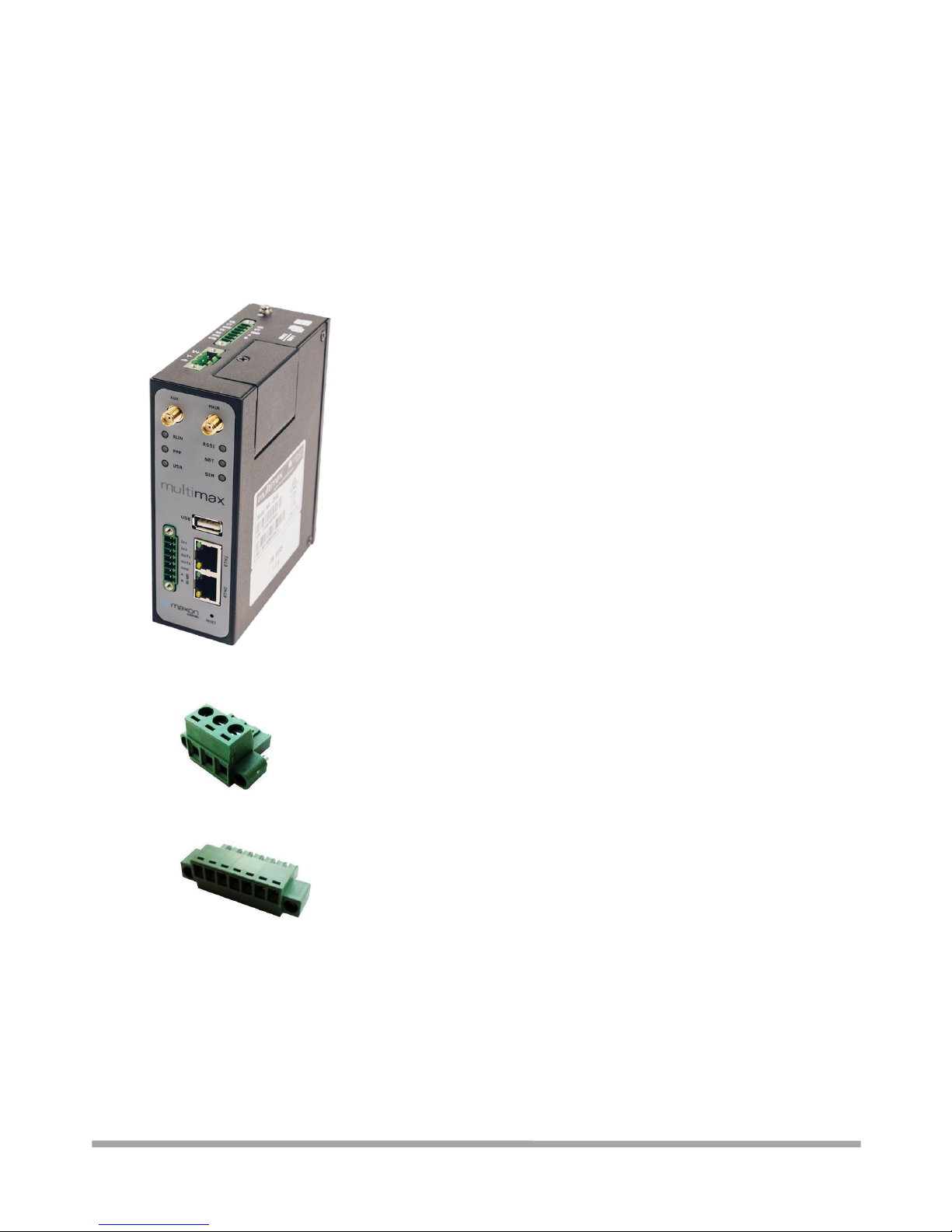
1 x Multimax MA-2040 Industrial Dual SIM Cellular VPN Router
1 x 3-pin 5 mm male terminal block with lock for power supply
1 x 7-pin 3.5 mm male terminal block with lock for serial port, I/O and console port
1 x Quick Start Guide with download link of other documents or tools
Note: If any of the above items is missing or damaged, please contact your Robustel sales
representative.
Optional Accessories (sold separately):
3G/4G SMA cellular antenna (stubby/magnet optional)
Page 6

Multimax_user manual_v.4.0.4 July. 11, 2018 6/139
Confidential
Stubby antenna Magnet antenna
RP-SMA WiFi antenna (stubby/magnet optional)
Stubby antenna Magnet antenna
Wall mounting kit
35 mm DIN rail mounting kit
Ethernet cable
AC/DC power adapter (12V DC, 1.5 A; EU/US/UK/AU plug optional)
Page 7

Multimax_user manual_v.4.0.4 July. 11, 2018 7/139
Confidential
Page 8

Multimax_user manual_v.4.0.4 July. 11, 2018 8/139
Confidential
1.3 Specifications
1.3.1 - Cellular Interface
Number of antennas: 2 (MAIN + AUX)
Connector: SMA female
SIM: 2 (3.0 V & 1.8 V)
Standards: GSM/GPRS/EDGE/WCDMA/HSDPA/HSUPA/HSPA+/DC-HSPA+/TD-SCDMA/CDMA
(CDMA
1X/EVDO)/FDD LTE/TDD LTE
GSM: max DL/UL = 9.6/2.7 Kbps
GPRS: max DL/UL = 86 Kbps
EDGE: max DL/UL = 236.8 Kbps
WCDMA/TD-SCDMA: max DL/UL = 2.8 Mbps/384 Kbps
EVDO: max DL/UL = 5.4 Mbps/14.7 Kbps
HSPA+: max DL/UL = 21/5.76 Mbps, fallback to 2G
DC-HSPA+: max DL/UL = 42/5.76 Mbps, fallback to 2G
FDD LTE: max DL/UL = 100/50 Mbps, fallback to 2G/3G
TDD LTE: max DL/UL = 100/50 Mbps, fallback to 2G/3G
1.3.2 - Ethernet Interface
Number of ports: 2 x 10/100 Mbps, 2 x LAN or 1 x LAN + 1 x WAN
Magnet isolation protection: 1.5 KV
1.3.3 - Serial Interface
Number of ports: 1 x RS-232 + 1 x RS-485 or 2 x RS-232 or 2 x RS-485
Connector: 7-pin 3.5 mm female socket with lock
ESD protection: ±15 KV
Baud rate: 300 bps to 230400 bps
Parameters: 8E1, 8O1, 8N1, 8N2, 7E2, 7O2, 7N2, 7E1
RS-232: TxD, RxD, RTS, CTS, GND
RS-485: Data+ (A), Data- (B)
1.3.4 - DI/DO
Type: 2 x DI (dry contact) + 2 x DO (wet contact), 4 x DI, 4 x DO, 3 x DI + 1 x DO or 3 x DO + 1 x
DI
Connector: 7-pin 3.5 mm female socket with lock
Isolation: 3KVDC or 2KVrms
Absolute maximum VDC: “V+” +5V DC (DI), 30V DC (DO)
Absolute maximum ADC: 300 mA
1.3.5 - Others
1 x RST button
1 x Micro SD interface
Page 9

Multimax_user manual_v.4.0.4 July. 11, 2018 9/139
Confidential
1 x USB 2.0 host up to 480 Mbps
1 x CLI interface
LED indicators - 1 x RUN, 1 x PPP, 1 x USR, 1 x RSSI, 1 x NET, 1 x SIM
1.3.6 - Software
Network protocols: PPP, PPPoE, TCP, UDP, DHCP, ICMP, NAT, HTTP, HTTPs, DNS, ARP, NTP,
SMTP, Telnet, VLAN, SSH2, DDNS, etc.
VPN tunnel: IPsec, OpenVPN, GRE, L2TP,PPTP
Firewall: DMZ, anti-DoS, Filtering (IP/Domain name/MAC address), Port Mapping, Access
Control
Management: Web, CLI, SMS
Serial port: Transparent, TCP Client/Server, UDP, Modbus RTU Gateway
1.3.7 - App Centre (Available Apps)
Apps*: L2TP, PPTP, DMVPN, maXconnect, VRRP, QoS, SNMP, Language, *Request on demand.
1.3.8 – Power Supply and Consumption
Connector: 3-pin 5 mm female socket with lock
Input voltage: 9 to 60V DC
Power consumption: Idle: 100 mA@12 V
Data link: 400 mA (peak) @12 V
1.3.9 - Physical Characteristics
Ingress protection: IP30
Housing & Weight: Metal, 570 g
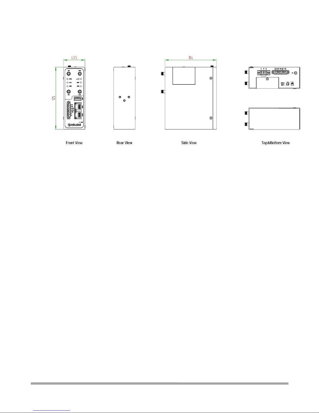
Dimensions: 125 x 104 x 43.5 mm
Installations: Desktop, wall mounting or 35 mm DIN rail mounting
1.3.10 - Certifications
Approvals & Certificates: CE, R & TTE,FCC, PTCRB, GCF, AT & T, IC, Rogers, RCM, CB, E-Mark,
NBTC, RoHS, WEEE
EMC:
EMI: EN 55022: 2006/A1: 2007 (CE & RE) Class B
EMS: IEC 61000-4-2 (ESD) Level 4
IEC 61000-4-3 (RS) Level 4
IEC 61000-4-4 (EFT) Level 4
IEC 61000-4-5 (Surge) Level 3
IEC 61000-4-6 (CS) Level 4
IEC 61000-4-8 (M/S) Level 4
Page 10
Multimax_user manual_v.4.0.4 July. 11, 2018 10/139
Confidential
1.4 Dimensions
Page 11
Multimax_user manual_v.4.0.4 July. 11, 2018 11/139
Confidential
Chapter 2 Hardware Installation
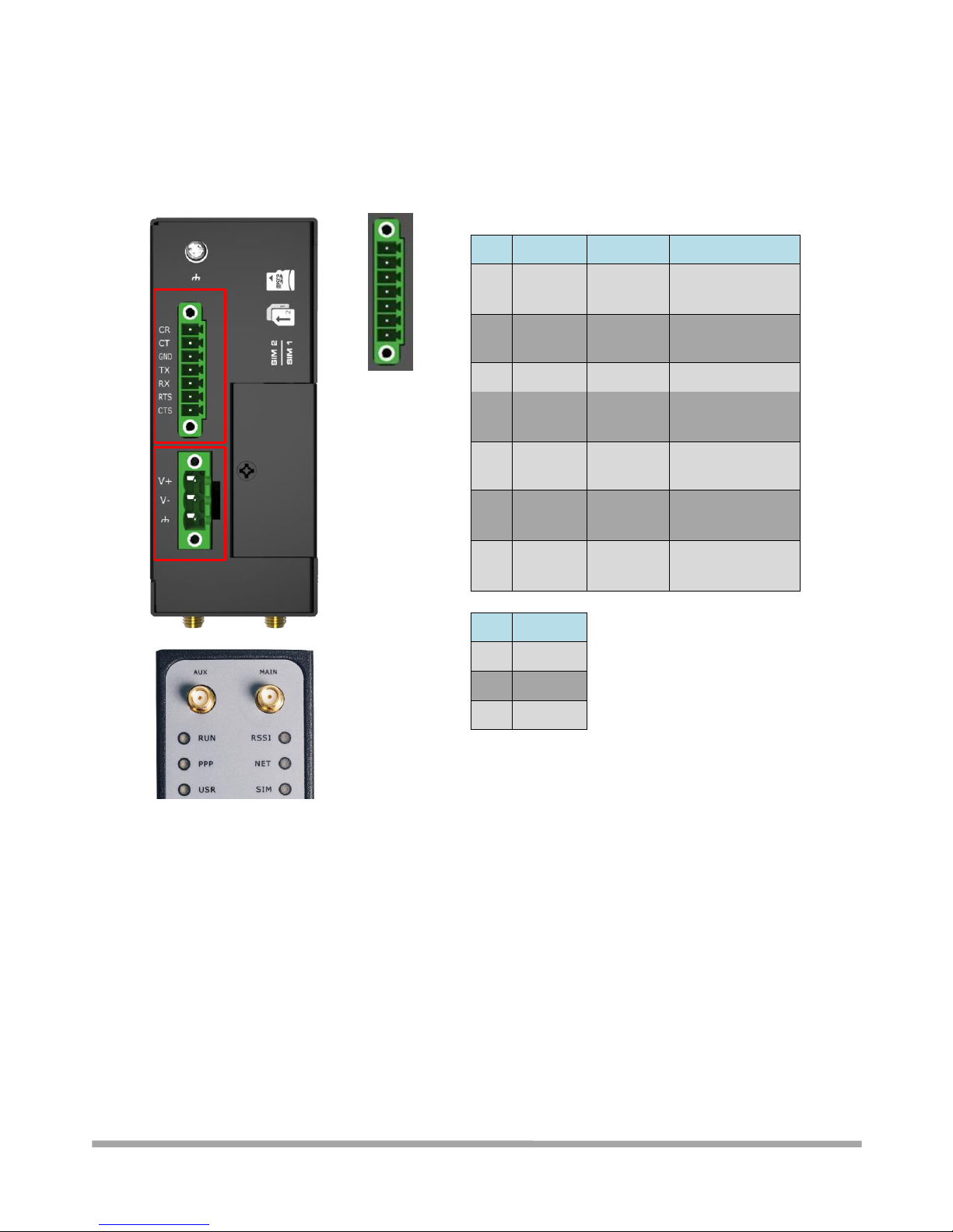
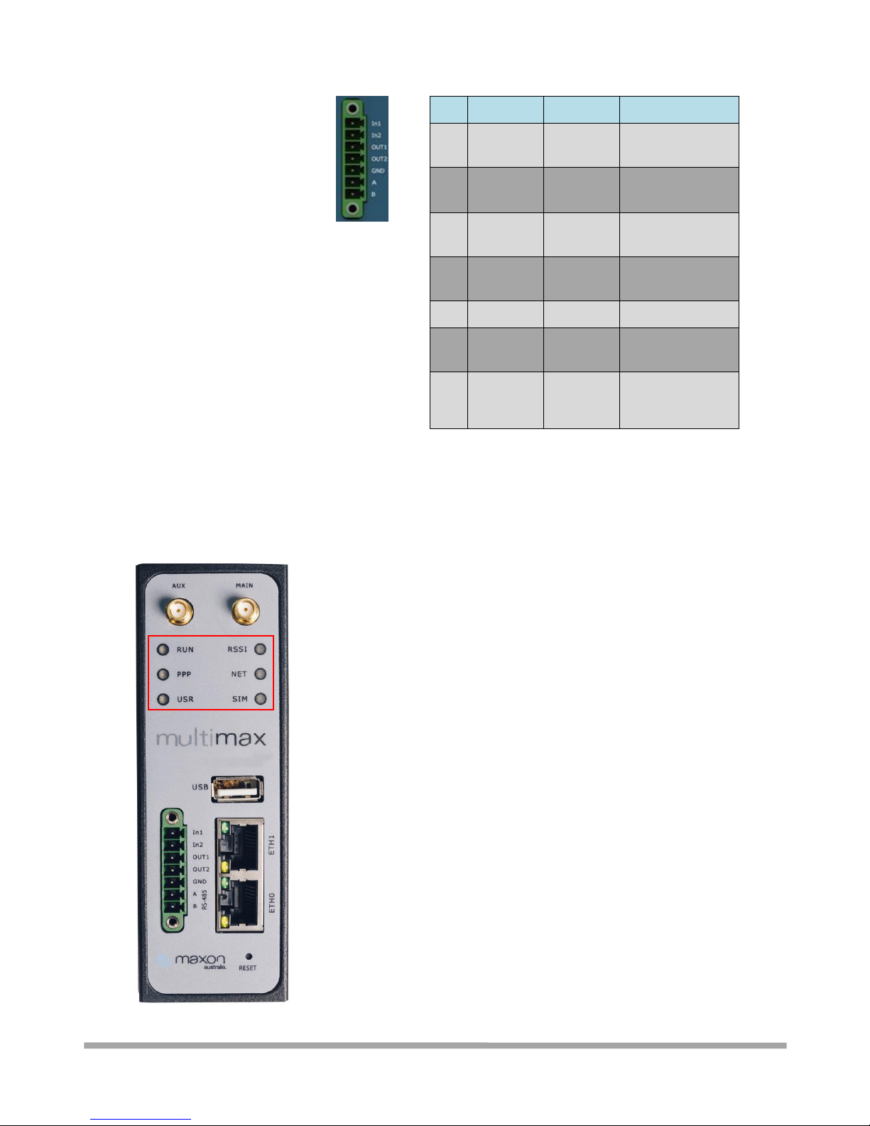
2.1 PIN Assignment
PIN
Debug
RS-232
Direction
1
CR
--
To MULTIMAX
From Device
2
CT
--
From MULTIMAX
To Device
3
GND
GND
--
4
--
TXD
To MULTIMAX
From Device
5
--
RXD
From MULTIMAX
To Device
6
--
RTS
To MULTIMAX
From Device
7
--
CTS
From MULTIMAX
To Device
PIN
Power
8
Positive
9
Negative
10
GND
Page 12
Multimax_user manual_v.4.0.4 July. 11, 2018 12/139
Confidential
PIN
DI/DO
RS-485
Direction
11
Input 1
--
To MULTIMAX
From Device
12
Input 2
--
To MULTIMAX
From Device
13
Output 1
--
From MULTIMAX
To Device
14
Output 2
--
From MULTIMAX
To Device
15
GND
--
--
16
--
Data+(A)
Half duplex RS485 +ve side
17
--
Data- (B)
Half duplex RS485 –ve side
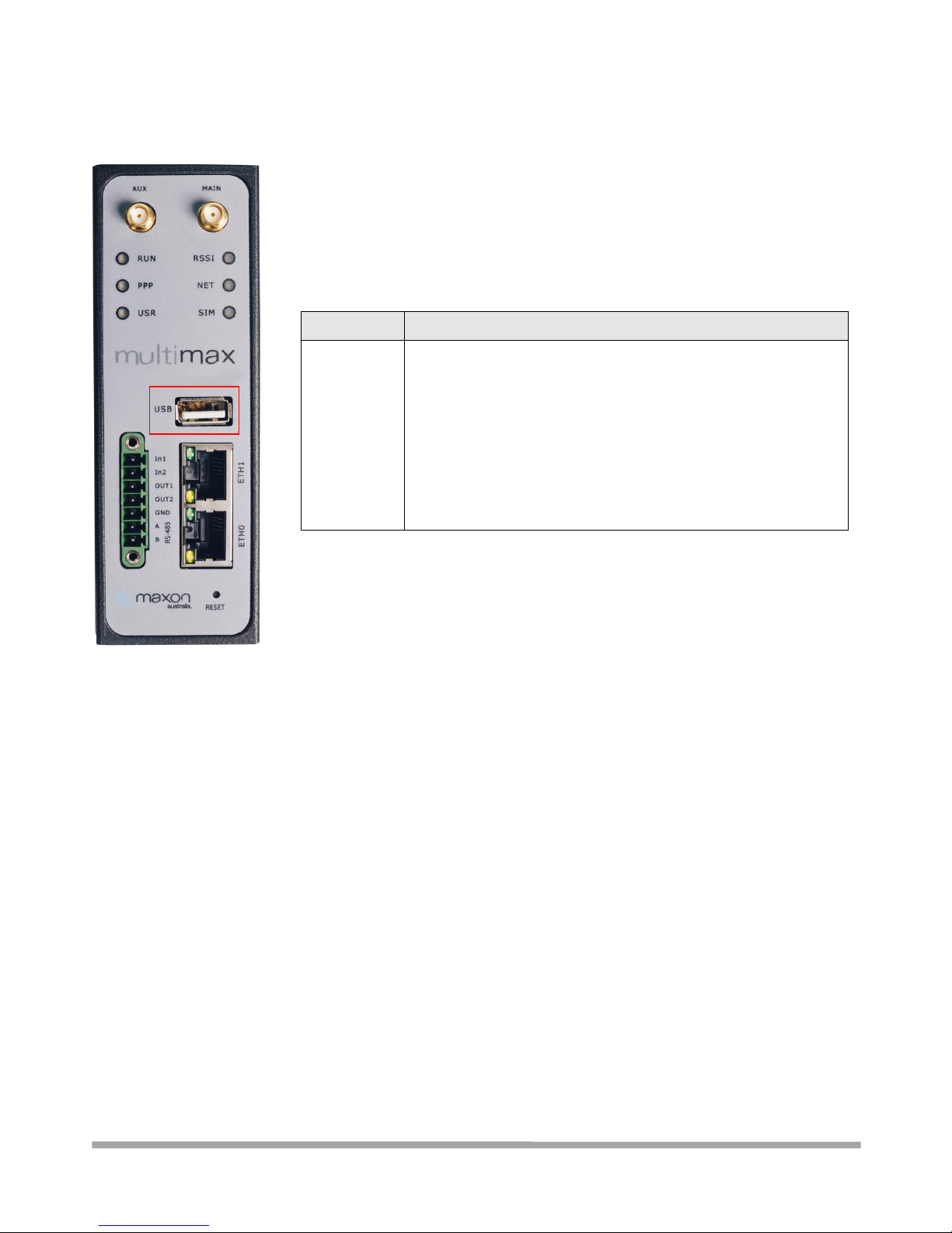
2.2 LED Indicators
Page 13

Multimax_user manual_v.4.0.4 July. 11, 2018 13/139
Confidential
Note: You can choose the display type of USR LED. For more details, please refer to 3.9.10 Service >
Advanced.
Name
Color
Status
Description
RUN
Green
On, fast blinking
(250 mSec blink time)
Router is powered on
(System is initializing)
On, blinking
(500 mSec blink time)
Router is operating
Off
Router is powered off
PPP
Green
On, solid
Link connection is working
Off
Link connection is not working
USR-OpenVPN
Green
On, solid
OpenVPN connection is established
Off
OpenVPN connection is not established
USR-IPsec
Green
On, solid
IPsec connection is established
Off
IPsec connection is not established
Green
On, solid
High Signal strength (21-31) is available
Yellow
On, solid
Medium Signal strength (11-20) is available
Red
On, solid
Low Signal strength (1-10) is available
--
Off
No signal
NET
Green
On, solid
Connection to 4G network is established
Yellow
On, solid
Connection to 3G network is established
Red
On, solid
Connection to 2G network is established
--
Off
Connection to network is not established or is currently
establishing
SIM
Green
On, blinking
Backup card is being used
Off
Main card is being used
Page 14
Multimax_user manual_v.4.0.4 July. 11, 2018 14/139
Confidential
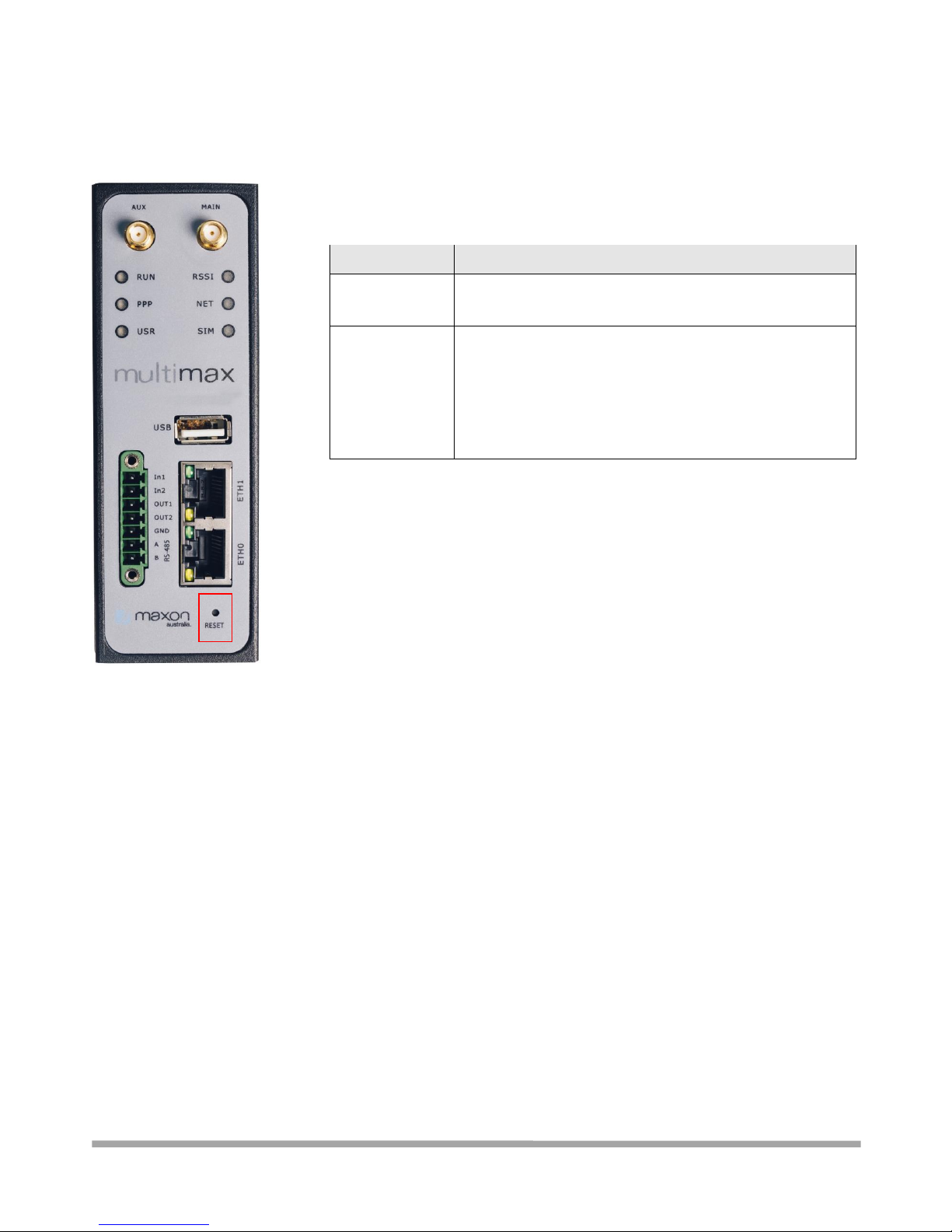
2.3 USB Interface
Function
Operation
Firmware
upgrade
USB interface is used for batch firmware upgrading, but cannot
be used for sending or receiving data from slave devices which
connected to it. You can insert a USB storage device into the
router’s USB interface, such as a U disk or a hard disk. If there
have a supported configuration file or a router firmware in this
USB storage device, the router will automatically update the
configuration file or the firmware. For more details, see 3.6.6
Interface > USB.
Page 15
Multimax_user manual_v.4.0.4 July. 11, 2018 15/139
Confidential
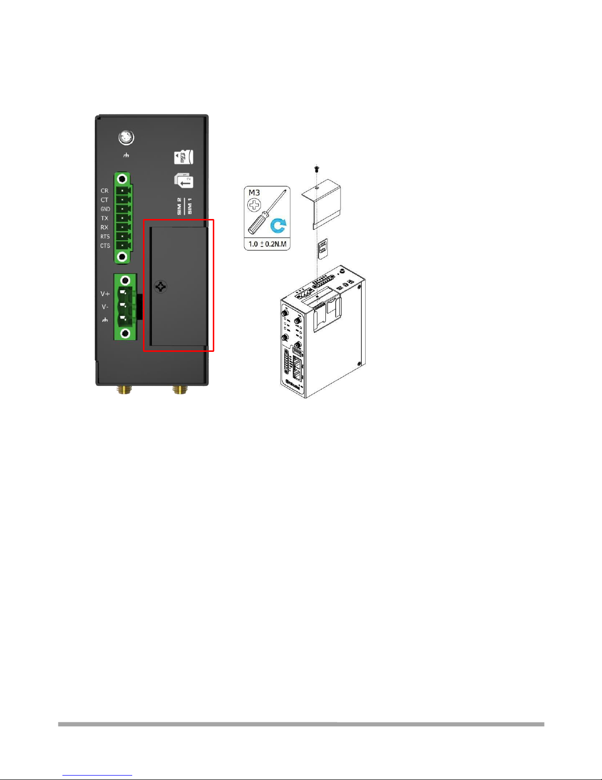
2.4 Reset Button
Function
Operation
Reboot
Press and hold the RST button for at least 5 seconds under
the operating status.
Restore to
factory default
settings
You must power off the modem and power on and wait
for 5 seconds after powering up the router, press and hold
the RST button until all six LEDs start blinking one by one,
and release the button to return the router to factory
defaults. NOTE: this will go back to factory settings NOT
the saved default configuration!
Page 16

Multimax_user manual_v.4.0.4 July. 11, 2018 16/139
Confidential
2.5 Ethernet Ports
There are two Ethernet ports, ETH0 and ETH1. Each Ethernet port has two LED indicators. The
yellow one is a link indicator, while the green one is a speed indicator. For details about status, see
the table below.
Indicator
Status
Description
Link indicator
On, solid
Connection is established
On, blinking
Data is being transferred
Off
Connection is not established
Speed indicator
On, solid
100 Mbps mode
Off
10 Mbps mode
Page 17
Multimax_user manual_v.4.0.4 July. 11, 2018 17/139
Confidential
2.6 Insert or Remove SIM Card/Micro SD Card
Insert or remove the SIM/Micro SD card as shown in the following steps.
Insert SIM card/Micro SD card
1. Make sure router is powered off.
2. To remove slot cover, loosen the screw associated with the cover by using a screwdriver and
then put the SIM card into the SIM slot/SD card slot.
3. To insert SIM card/Micro SD card, press the card with finger until you hear a click.
4. Put back the cover and tighten the screws associated with the cover by using a screwdriver.
Remove SIM card/Micro SD card
1. Make sure router is powered off.
2. To remove slot cover, loosen the screw associated with the cover by using a screwdriver and
then find the SIM card slot/SD card slot.
3. To remove SIM card/Micro SD card, press the card with finger until it pops out and then take
out the card.
4. Put back the cover and tighten the screw associated with the cover by using a screwdriver.
Note:
1. Recommended torque for inserting is 0.5 N.m, and the maximum allowed is 0.7 N.m.
Page 18

Multimax_user manual_v.4.0.4 July. 11, 2018 18/139
Confidential
2. Use the high temperature specific card when the device is working in extreme temperature
(temperature exceeding 40 °C), because the regular card for long-time working in harsh
environment will tend to disconnect frequently.
3. Do not forget to tighten the cover well to avoid the SIM/SD card being stolen.
4. Do not touch the metal of the card surface as information in the card may be lost or destroyed.
5. Do not bend or scratch the card.
6. Keep the card away from electricity and magnetism.
7. Make sure router is powered off before inserting or removing the card.
Page 19
Multimax_user manual_v.4.0.4 July. 11, 2018 19/139
Confidential
2.7 Attach External Antenna (SMA Type)
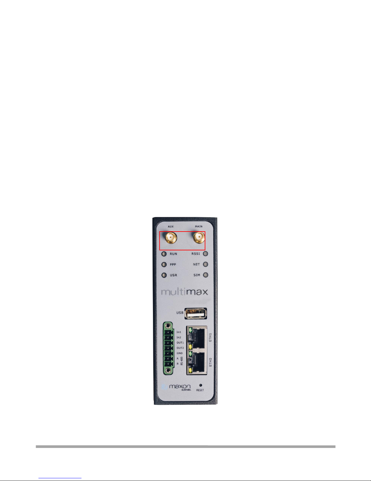
Attach an external SMA antenna to the router’s antenna connector and tighten. Make sure the
antenna is within the correct frequency range provided by the ISP and with 50 Ohm impedance.
Note: Recommended torque for tightening is 0.35 N.m.
The “MAIN” connection is REQUIRED, while the “AUX” is optional – modem behaviour may be more
stable in margin areas and in mobile applications when using the AUX connector.
Page 20
Multimax_user manual_v.4.0.4 July. 11, 2018 20/139
Confidential
2.8 Mount the Router
The router can be placed on a desktop or mounted to a wall or a 35 mm DIN rail.
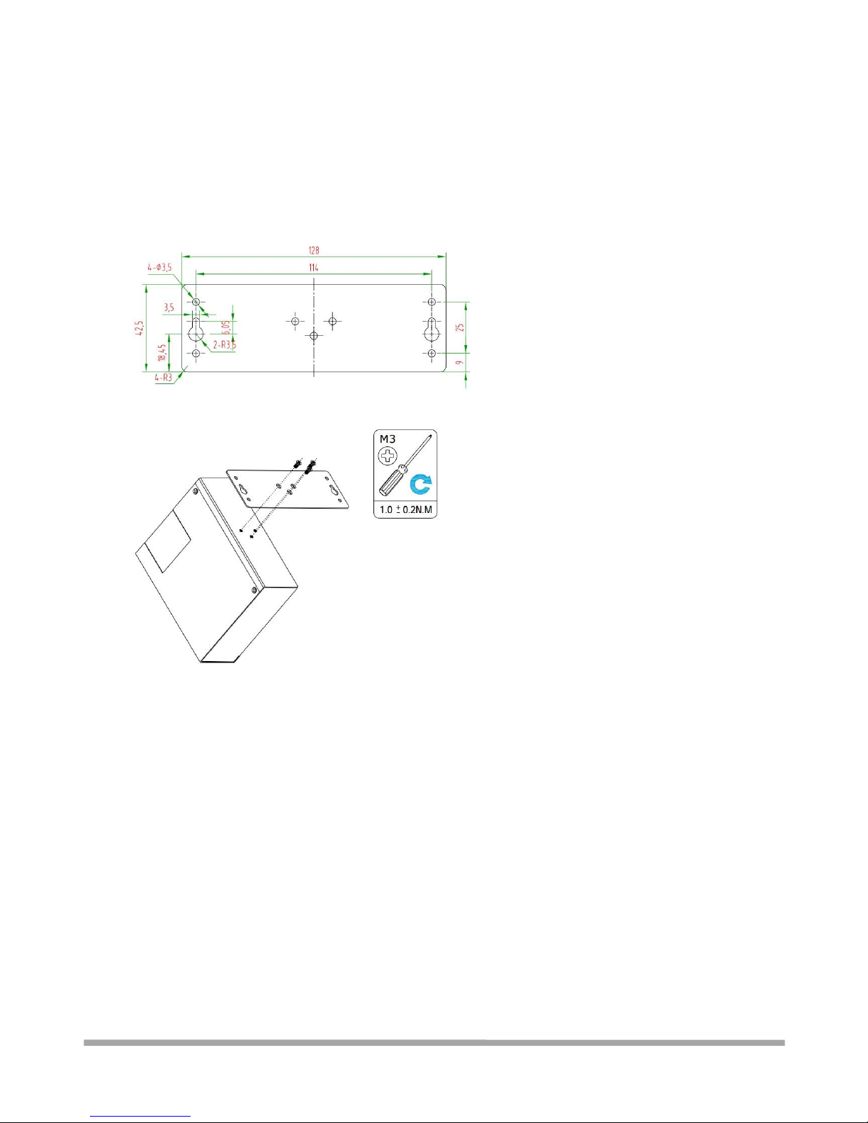
2.8.1 - Two methods for mounting the router
1. Wall mounting (measured in mm)
Use 3 pcs of M3*4 flat head Phillips screws to fix the wall mounting kit to the router, and then
use 2 pcs of M3 drywall screws to mount the router associated with the wall mounting kit on
the wall.
Note: Recommended torque for mounting is 1.0 N.m, and the maximum allowed is 1.2 N.m.
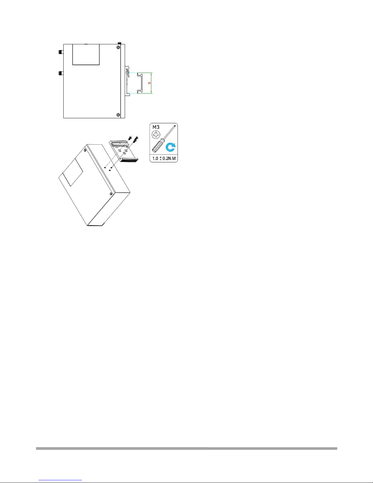
2. DIN rail mounting (measured in mm)
Page 21
Multimax_user manual_v.4.0.4 July. 11, 2018 21/139
Confidential
Use 3 pcs of M3*6 flat head Phillips screws to fix the DIN rail to the router, and then hang the
DIN rail on the mounting bracket. It is necessary to choose a standard bracket.
Note: Recommended torque for mounting is 1.0 N.m, and the maximum allowed is 1.2 N.m.
Page 22
Multimax_user manual_v.4.0.4 July. 11, 2018 22/139
Confidential
2.9 Ground the Router
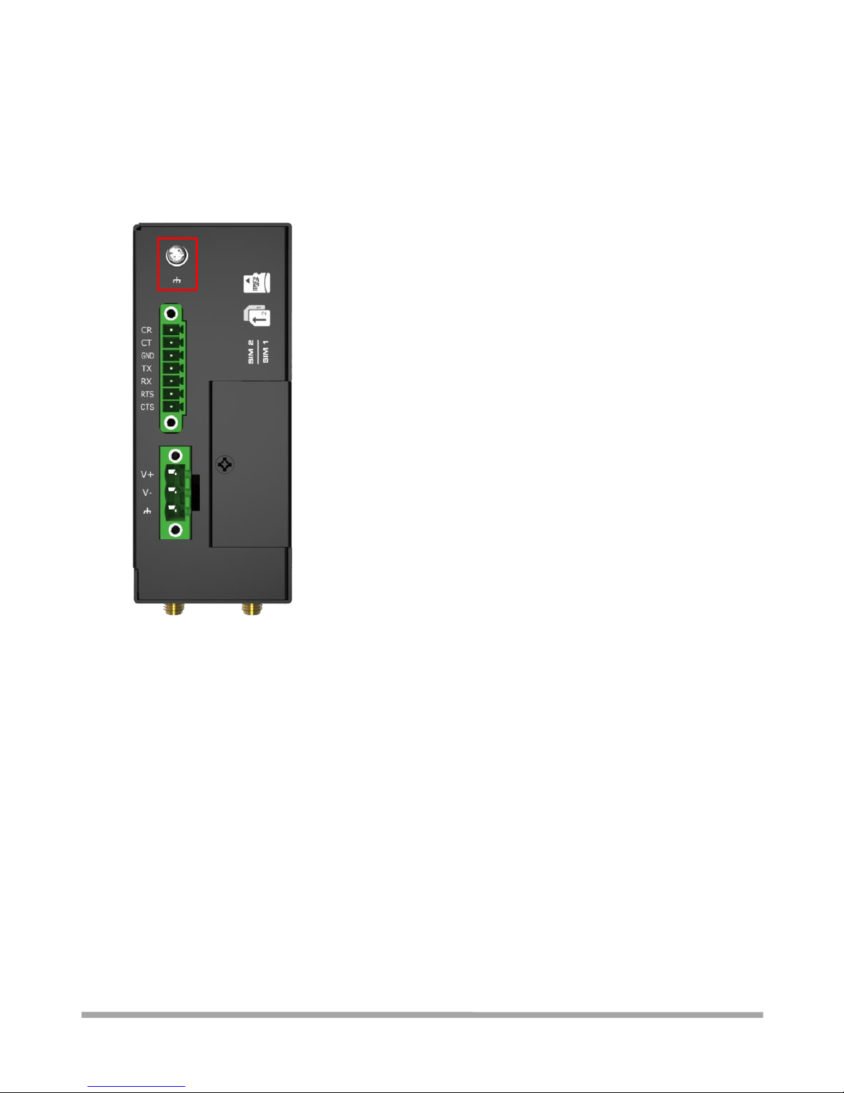
Router grounding helps prevent the noise effect due to electromagnetic interference (EMI).
Connect the router to the site ground wire by the ground screw before powering on.
Note: This product is appropriate to be mounted on a well grounded device surface, such as a metal
panel.
Page 23
Multimax_user manual_v.4.0.4 July. 11, 2018 23/139
Confidential
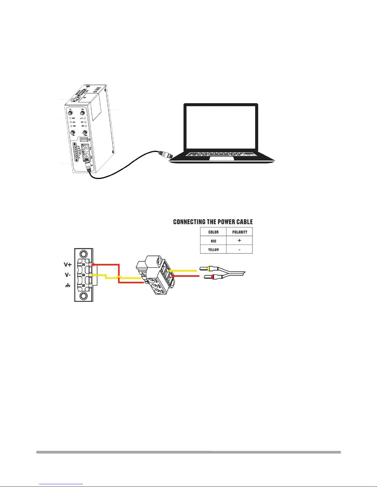
2.10 Connect the Router to a Computer
Connect one end of an Ethernet cable to the port marked ETH0 or ETH1 and the other end of the
cable to your computer.
2.11 Power Supply
Multimax Router has reverse polarity protection, but always refers to the figure above to
connect the power adapter correctly. There are two cables associated with the power
adapter. Following to the colour of the head, connect the cable marked red to the positive
pole through a terminal block, and connect the yellow one to the negative in the same way.
The last step is to plug the power adapter into your socket. Note: The range of power
voltage is 9 to 60V DC.
Page 24
Multimax_user manual_v.4.0.4 July. 11, 2018 24/139
Confidential
Chapter 3 Initial Configuration
The router can be configured through your web browser that including IE 8.0 or above, Chrome and
Firefox, etc. A web browser is included as a standard application in the following operating systems:
Linux, Mac OS, Windows 98/NT/2000/XP/Me/Vista/7/8/10, etc. It provides an easy and userfriendly interface for configuration. There are various ways to connect the router, either through an
external repeater/hub or connect directly to your PC. However, make sure that your PC has an
Ethernet interface properly installed prior to connecting the router. You must configure your PC to
obtain an IP address through a DHCP server or a fixed IP address that must be in the same subnet
as the router. If you encounter any problems accessing the router web interface, it is advisable to
uninstall or disable your firewall program on your PC, as this can prevent access to the IP address of
the router.
3.1 Configure the PC
There are two methods to get IP address for the PC. One is to obtain an IP address automatically
from “Local Area Connection”, and another is to configure a static IP address manually within the
same subnet of the router. Please refer to the steps below.
Here take Windows 7 as example, and the configuration for windows system is similar.
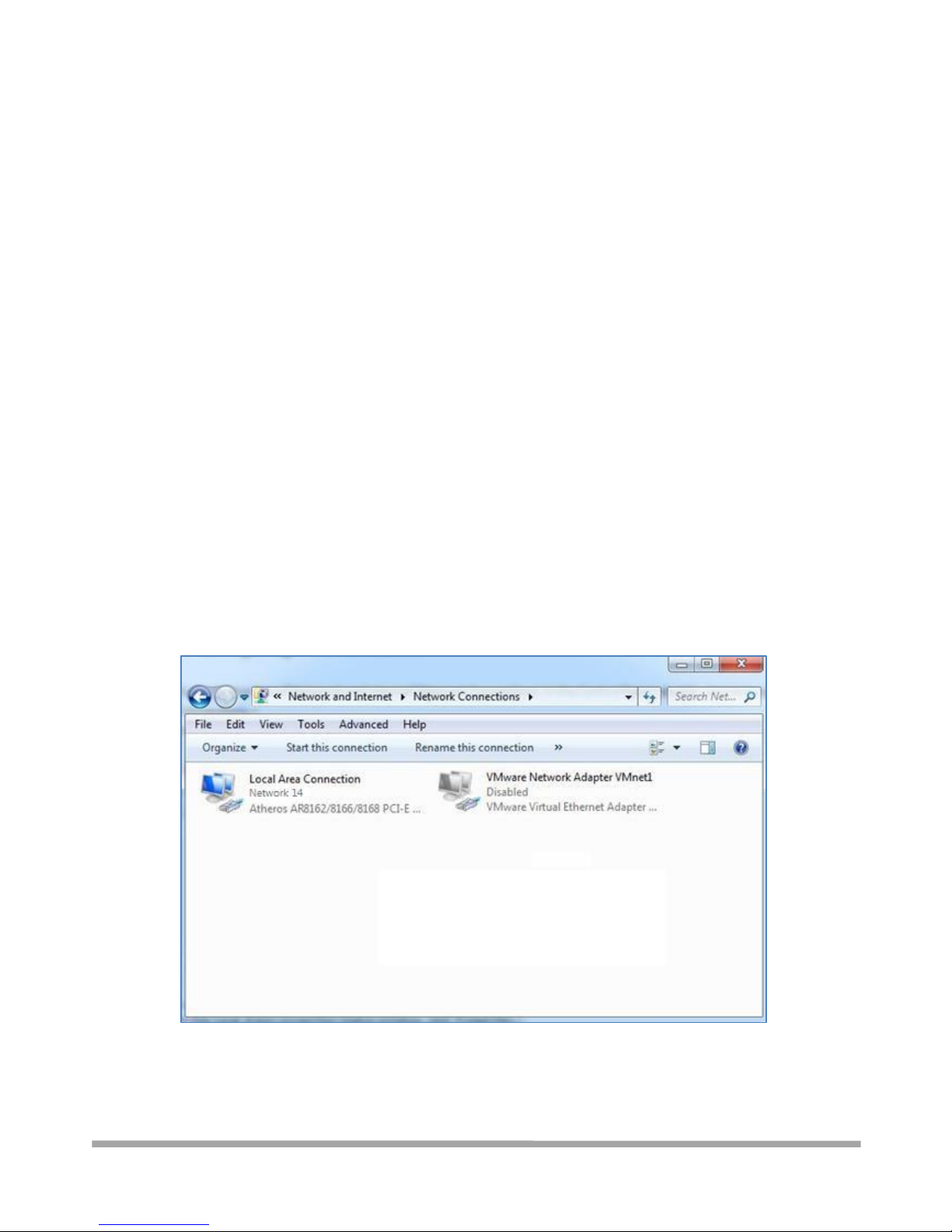
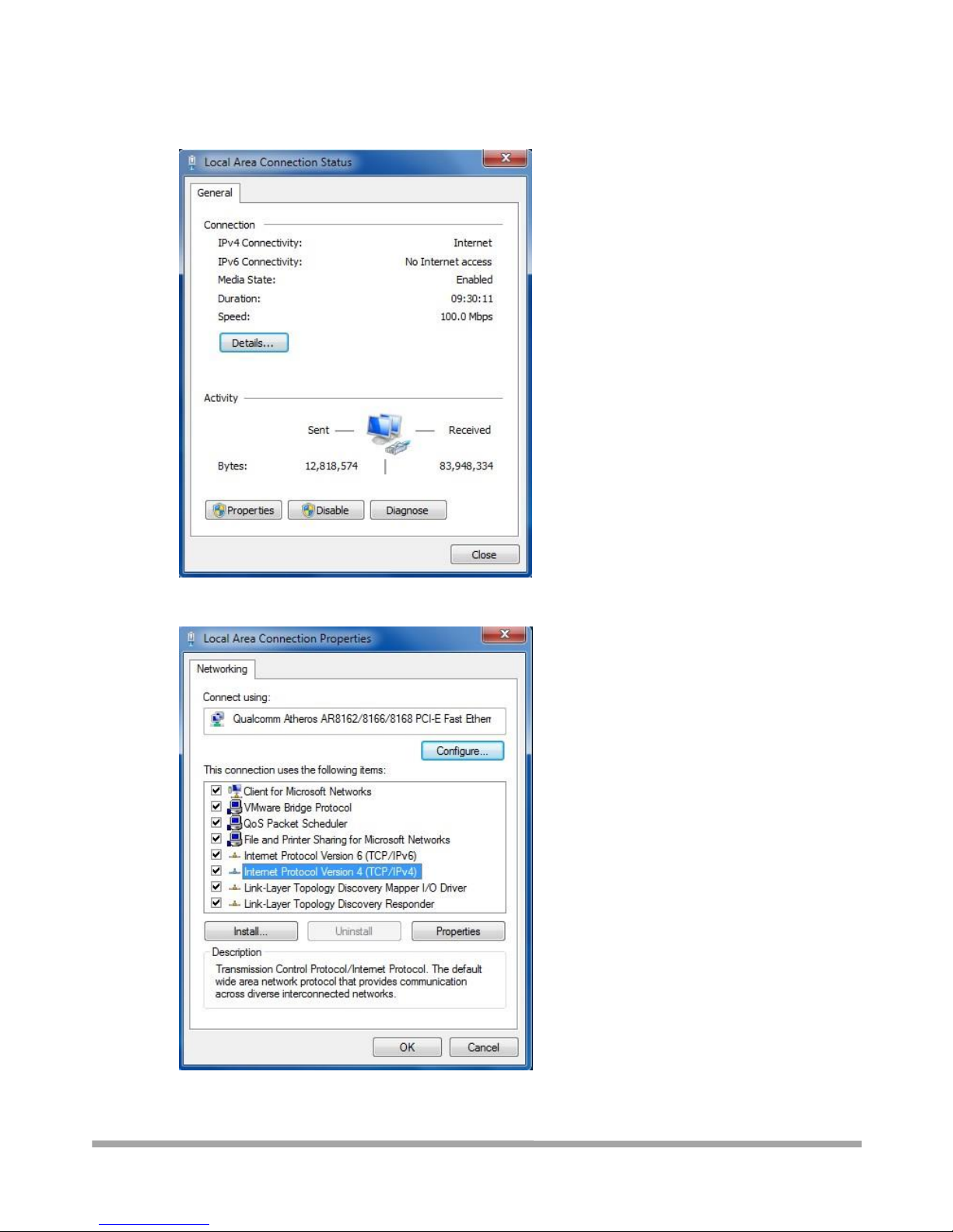
1. Click Start > Control panel, double-click Network and Sharing Center, and then double-click
Local Area Connection.
Page 25
Multimax_user manual_v.4.0.4 July. 11, 2018 25/139
Confidential
2. Click Properties in the window of Local Area Connection Status.
3. Choose Internet Protocol Version 4 (TCP/IPv4) and click Properties.
Page 26
Multimax_user manual_v.4.0.4 July. 11, 2018 26/139
Confidential
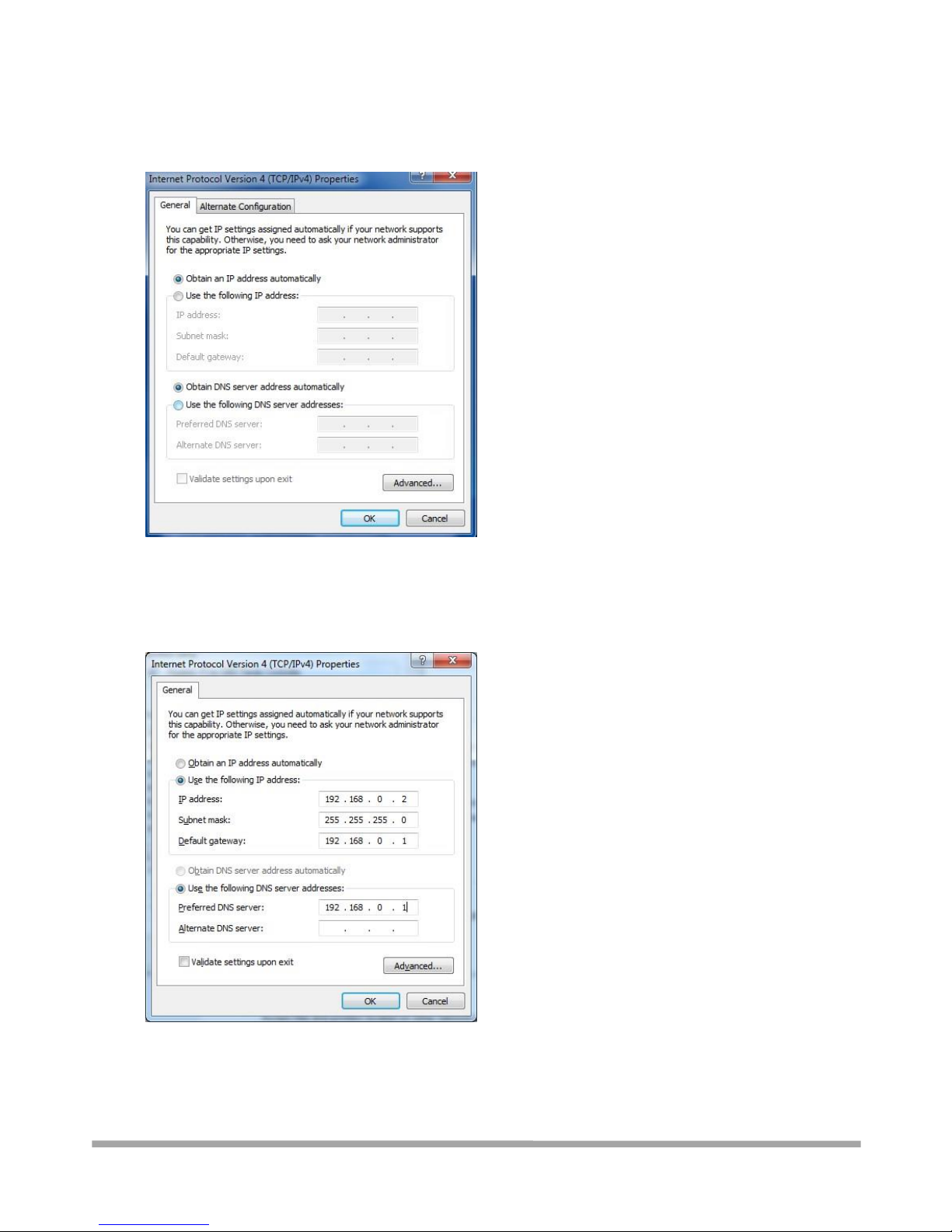
4. Two ways for configuring the IP address of PC
Obtain an IP address automatically:
Use the following IP address:
(Configured a static IP address manually within the same subnet
of the router)
5. Click OK to finish the configuration.
Page 27
Multimax_user manual_v.4.0.4 July. 11, 2018 27/139
Confidential
3.2 Factory Default Settings
Before configuring your router, you need to know the following default settings.
Item
Description
Username
admin
Password
admin
ETH0
192.168.0.1/255.255.255.0, LAN mode
ETH1
192.168.0.1/255.255.255.0, LAN mode
DHCP Server
Enabled
3.3 Log in the Router
To log in to the management page and view the configuration status of your router, please follow
the steps below.
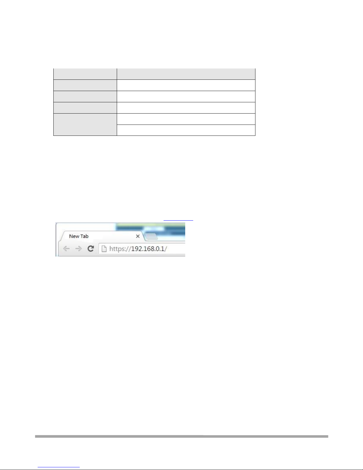
1. On your PC, open a web browser such as Internet Explorer, Google and Firebox, etc.
2. From your web browser, type the IP address of the router into the address bar and press enter.
The default IP address of the router is 192.168.0.1, though the actual address may vary.
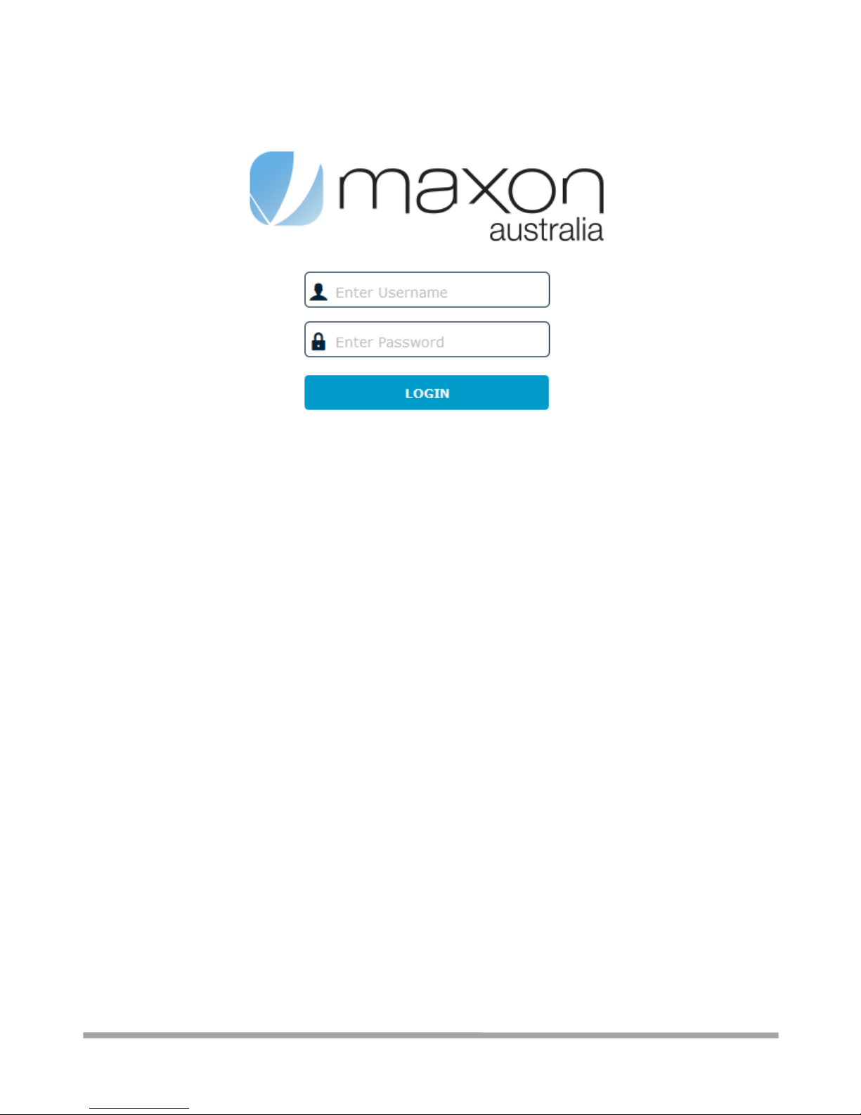
3. In the login page, enter the username and password, and then click LOGIN. The default
username and password are “admin”.
Note: If enter the wrong username or password over six times, the login web will be
locked for 5 minutes.
Page 28
Multimax_user manual_v.4.0.4 July. 11, 2018 28/139
Confidential
Page 29
Multimax_user manual_v.4.0.4 July. 11, 2018 29/139
Confidential
3.4 Control Panel
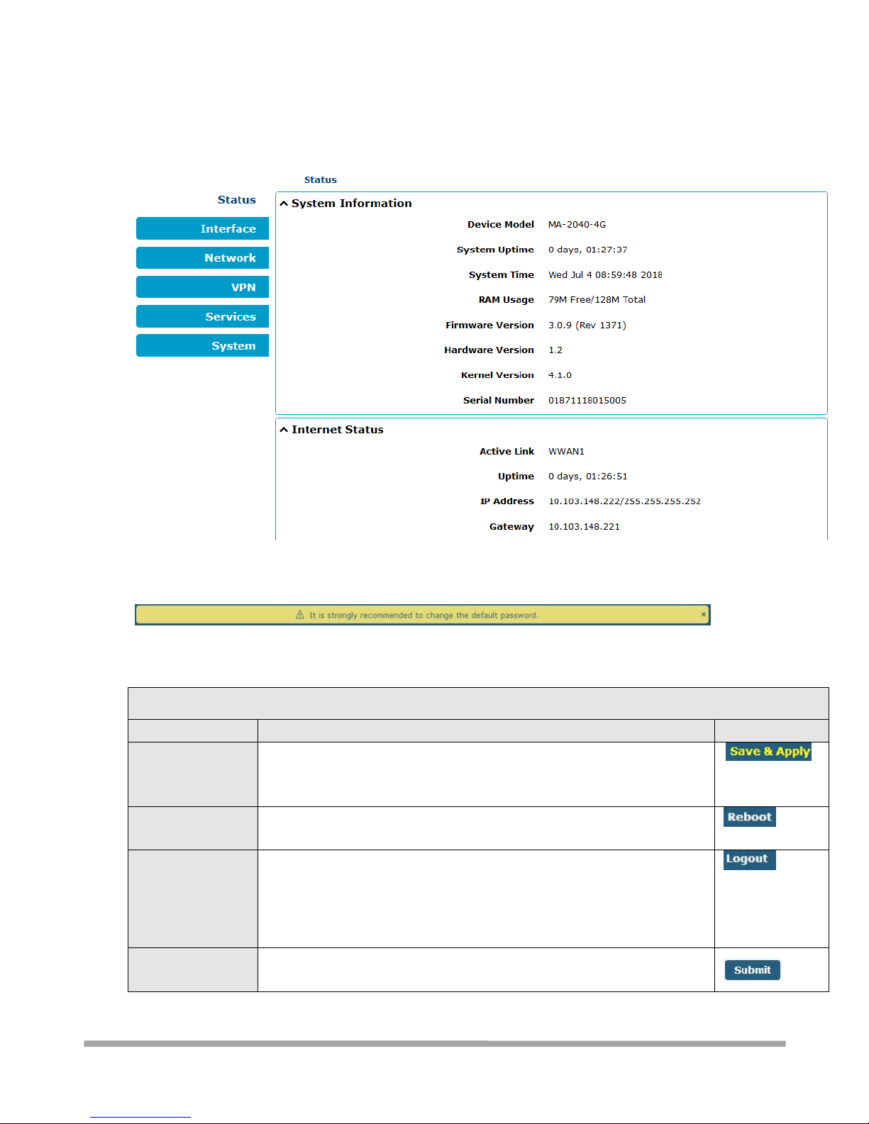
After logging in, the home page of the MULTIMAX Router’s web interface is displayed, for example.
Using the original password to log in the router, the page will pop up the following tab
It is strongly recommended for security purposes that you change the default username and/or
password. To change your username and/or password, see 3.9.16 System > User Management.
Control Panel
Item
Description
Button
Save & Apply
Click to save the current configuration into router’s flash and apply the
modification on every configuration page, to make the modification take
effect.
Reboot
Click to reboot the router. If the Reboot button is yellow, it means that
some completed configurations will take effect only after reboot.
Logout
Click to log the current user out safely. After logging out, it will switch to
login page. Shut down the web browser without logout, the next user can
login web on this browser without a password before timeout. (ie, it is
assumed if you don’t go through the logout process, you WANT to stay
logged in!)
Submit
Click to save the modification on current configuration page.
Page 30

Multimax_user manual_v.4.0.4 July. 11, 2018 30/139
Confidential
Cancel
Click to cancel the modification on current configuration page.
Note: The steps of how to modify configuration are as bellow:
1. Modify in one page;
2. Click under this page;
3. Modify in another page;
4. Click under this page;
5. Complete all modification;
6. Click .
Page 31
Multimax_user manual_v.4.0.4 July. 11, 2018 31/139
Confidential
3.5 - Status
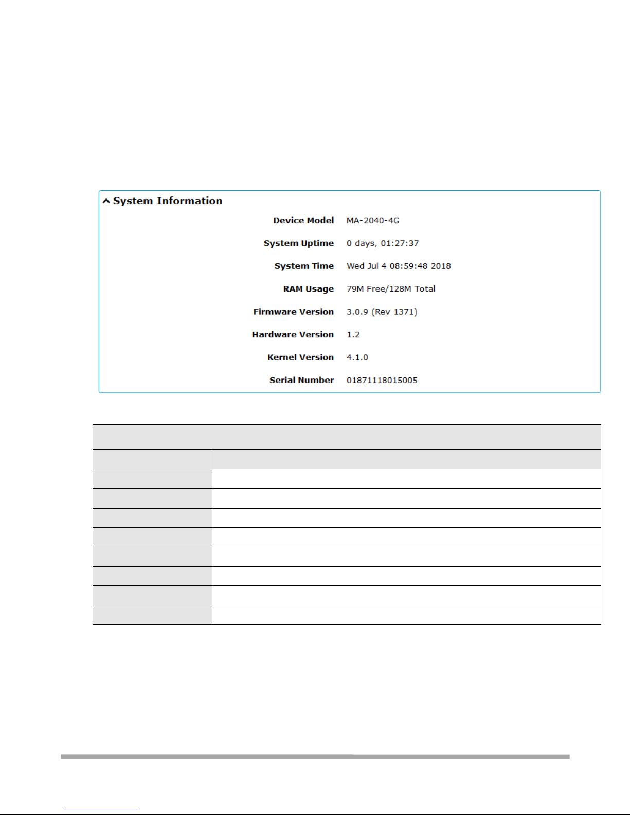
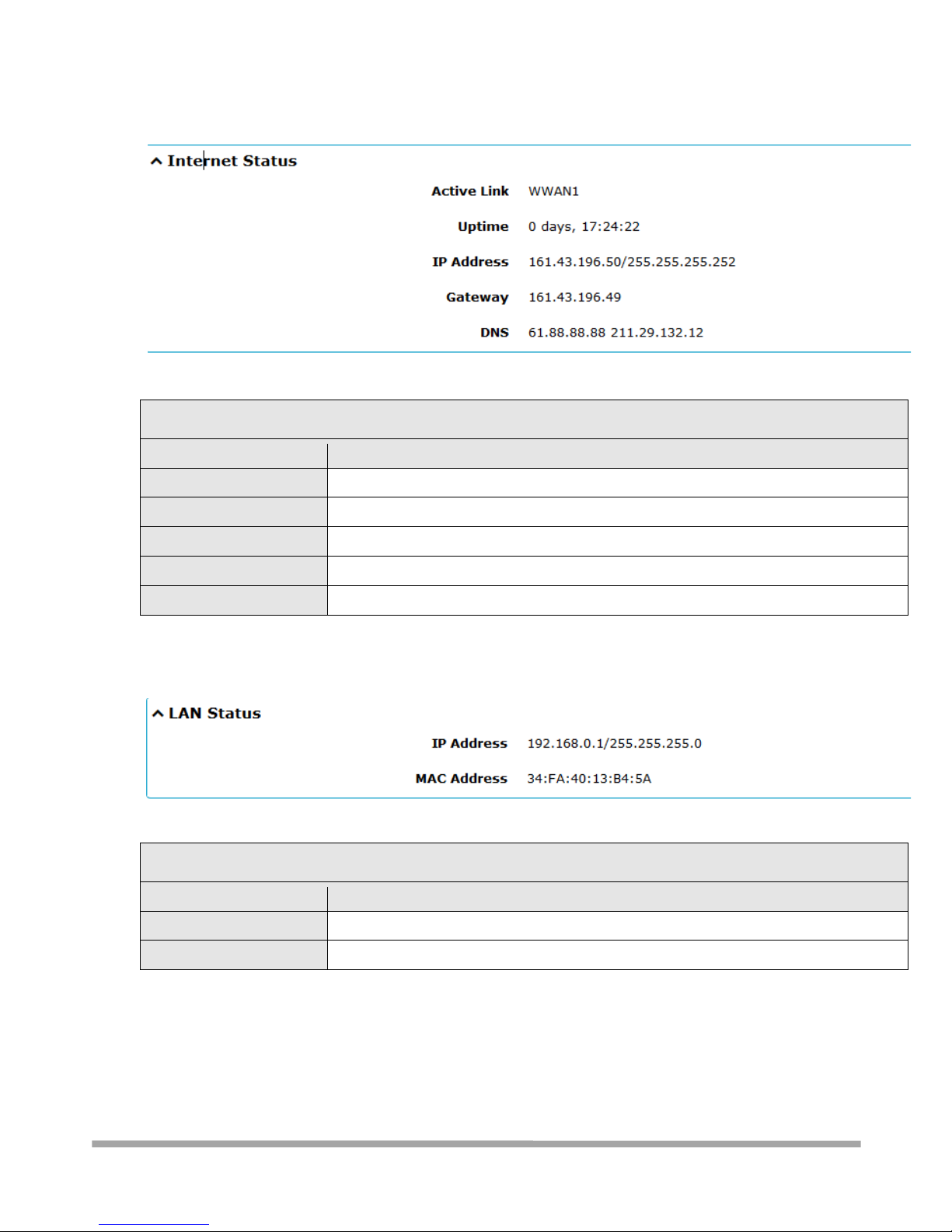
This page allows you to view the System Information, Internet Status and LAN Status of your
Router.
3.5.1 - System Information
System Information
Item
Description
Device Model
Show the model name of your device.
System Uptime
Show the current amount of time the router has been booted.
System Time
Show the current system time.
RAM Usage
Show the free memory and the total memory.
Firmware Version
Show the firmware version running on the router.
Hardware Version
Show the hardware version of your device.
Kernel Version
Show the kernel version of your device.
Serial Number
Show the serial number of your device.
Page 32
Multimax_user manual_v.4.0.4 July. 11, 2018 32/139
Confidential
3.5.2 - Internet Status
Internet Status
Item
Description
Active Link
Show the current active link.
Uptime
Show the current amount of time the link has been connected.
IP Address
Show the IP address of current link.
Gateway
Show the default gateway address of the current link.
DNS
Show the current primary DNS server and secondary server.
3.5.3 - LAN Status
LAN Status
Item
Description
IP Address
Show the IP address and the Netmask of the router.
MAC Address
Show the MAC address of the router.
Page 33
Multimax_user manual_v.4.0.4 July. 11, 2018 33/139
Confidential
3.6 - Interface
3.6.1 - Interface > Link Manager
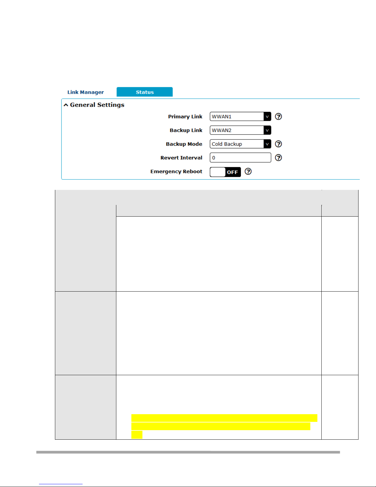
This section allows you to setup the link connection.
General Settings @ Link Manager
Item
Description
Default
Primary Link
Select from “WWAN1”, “WWAN2”, or “WAN”.
WWAN1: Makes SIM1 the primary wireless link
WWAN2: Makes SIM2 the primary wireless link
WAN: Make WAN Ethernet port the primary wired link Note: WAN link is
available only if enable eth0 as WAN port in Interface > Ethernet > Ports
> Port Settings.
WWAN1
Backup Link
Select from “None”, “WWAN1”, “WWAN2” or “WAN”.
None: Do not select any backup link
WWAN1: Make SIM1 the backup wireless link
WWAN2: Make SIM2 the backup wireless link
WAN: Make WAN Ethernet port the backup wired link Note: WAN link is
available only if enable eth0 as WAN interface in Interface > Ethernet >
Ports > Port Settings.
WWAN2
Backup Mode
Select from “Cold Backup”, “Warm Backup” or “Load Balancing”.
Cold Backup: The inactive link is offline on standby
Warm Backup: The inactive link is online on standby
Load Balancing: Use two links simultaneously
Note: Warm backup mode and Load Balancing are not available for dual
SIM backup (IE, you must be using a wired WAN for at least one WAN
link)
Cold
Backup
Page 34
Multimax_user manual_v.4.0.4 July. 11, 2018 34/139
Confidential
Revert Interval
Specify the number of minutes that elapses before the primary link is
checked if a backup link is being used in cold backup mode. 0 means disable
checking.
Note: Revert interval is available only under the cold backup mode.
0
Emergency Reboot
Click the toggle button to enable/disable this option. Enable to reboot the
whole system if no links available.
OFF
Note: Click for help.
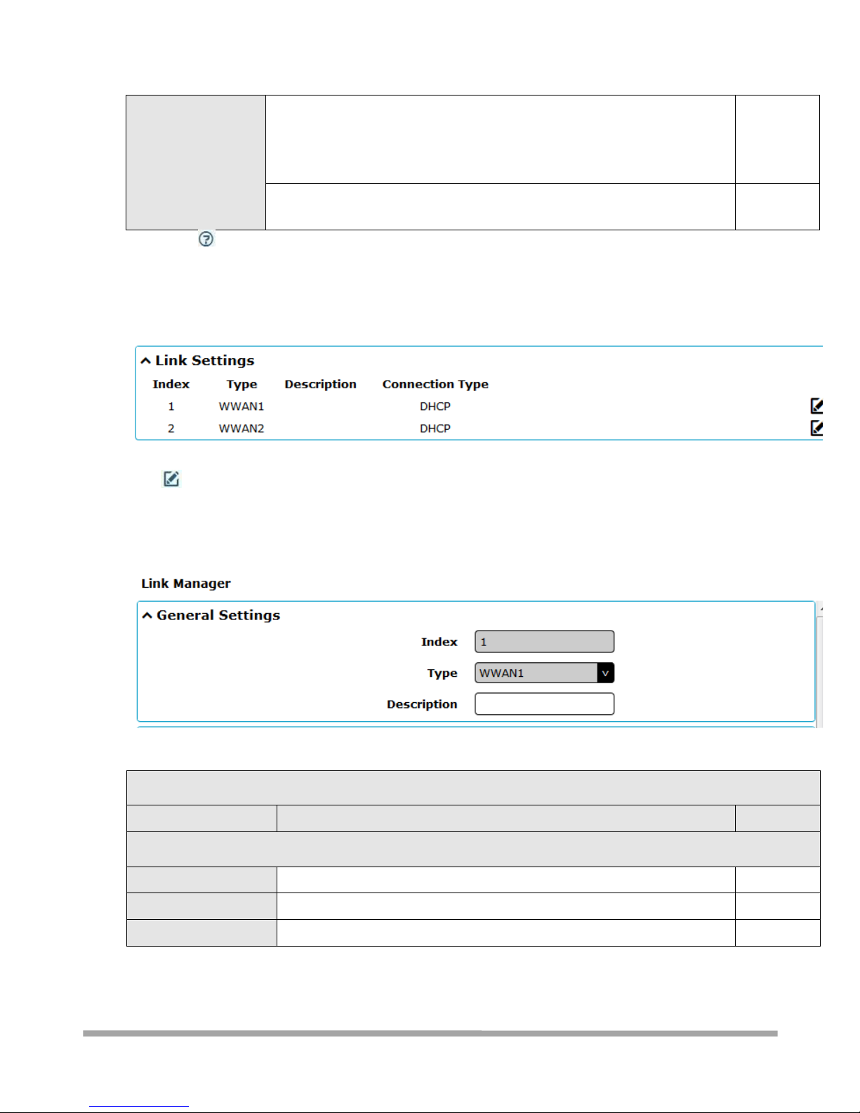
Link Settings allows you to configure the parameters of link connection, including
WWAN1/WWAN2 and WAN. It is recommended to enable Ping detection to keep the router online.
Ping detection increases the reliability of the WAN link, but costs some additional data traffic.
Click on the right-most of WWAN1/WWAN2 to enter the configuration window.
WWAN1/WWAN2
Link Settings (WWAN)
Item
Description
Default
General Settings
Index
Indicate the ordinal of the list.
--
Type
Show the type of the link.
WWAN1
Description
Enter a description for this link.
Null
Page 35
Multimax_user manual_v.4.0.4 July. 11, 2018 35/139
Confidential
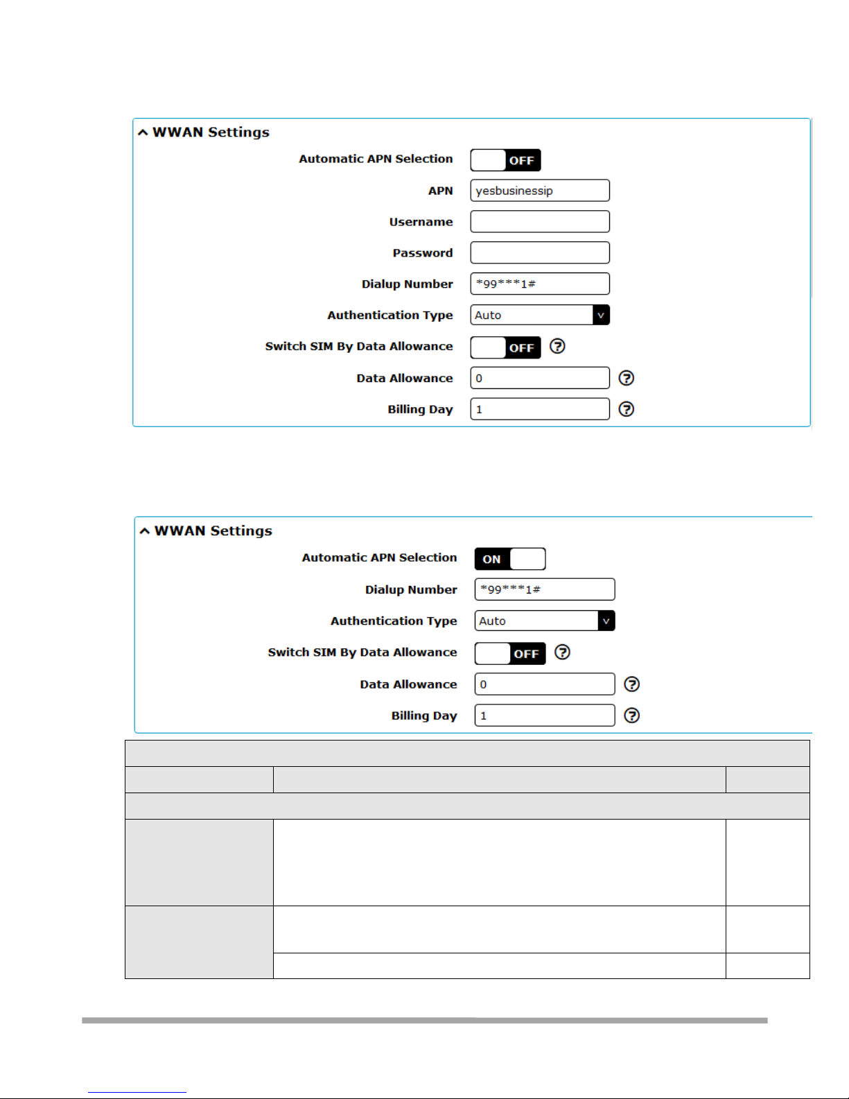
The window is displayed as below when disabling the “Automatic APN Selection” option.
The window is displayed as below when enabling the “Automatic APN Selection” option.
Link Settings (WWAN)
Item
Description
Default
WWAN Settings
Automatic APN
Selection
Click the toggle button to enable/disable the “Automatic APN Selection”
option. After enabling, the device will recognize the access point name
automatically. Alternatively, you can disable this option and manually add
the access point name.
ON
APN
Enter the Access Point Name for cellular dial-up connection, provided by
local ISP.
internet
Username
Enter the username for cellular dial-up connection, provided by local ISP.
Null
Page 36
Multimax_user manual_v.4.0.4 July. 11, 2018 36/139
Confidential
Password
Enter the password for cellular dial-up connection, provided by local ISP.
Null
Dialup Number
Enter the dialup number for cellular dial-up connection, provided by local
ISP.
*99***1#
Authentication Type
Select from “Auto”, “PAP” or “CHAP” as the local ISP required.
Auto
Switch SIM By Data
Allowance
Click the toggle button to enable/disable this option. After enabling, it will
switch to another SIM when the data limit reached.
Note: Only used for dual SIM backup.
OFF
Data Allowance
Set the monthly data traffic limitation. The system will record the data
traffic statistics when data traffic limitation (MiB) is specified. The traffic
record will be displayed in Interface > Link Manager > Status > WWAN
Data Usage Statistics. 0 means disable data traffic record.
0
Billing Day
Specify the monthly billing day. The data traffic statistics will be
recalculated from that day.
1
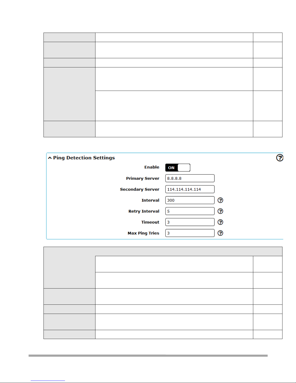
Ping Detection Settings
Enable
Click the toggle button to enable/disable the ping detection mechanism, a
keep-alive policy of the router.
ON
Primary Server
Router will ping this primary address/domain name to check that if the
current connectivity is active.
8.8.8.8
Secondary Server
Router will ping this secondary address/domain name to check that if the
current connectivity is active.
114.114.11
4.114
Interval
Set the ping interval.
300
Retry Interval
Set the ping retry interval. When ping failed, the router will ping again
every retry interval.
5
Timeout
Set the ping timeout.
3
Page 37
Multimax_user manual_v.4.0.4 July. 11, 2018 37/139
Confidential
Max Ping Tries
Set the max ping tries. Switch to another link or take emergency action if
the max continuous ping tries reached.
3
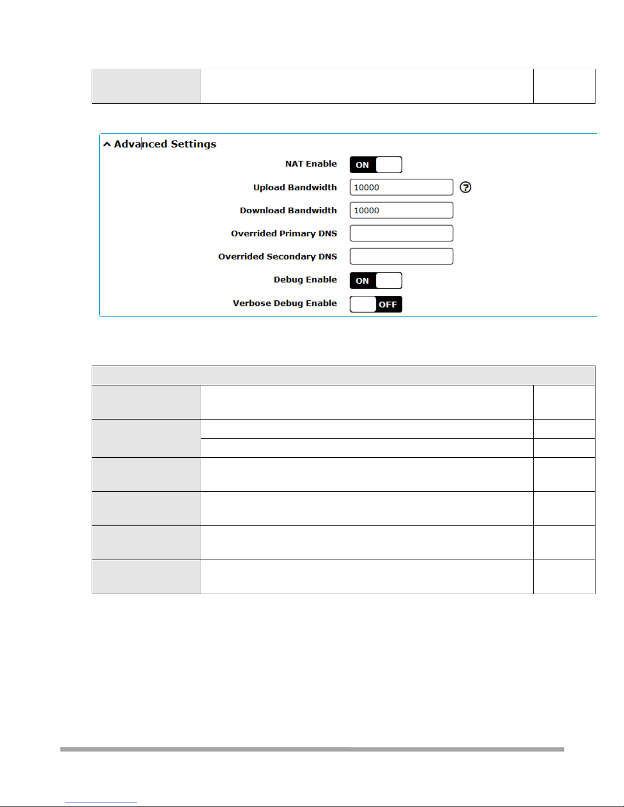
Advanced Settings
NAT Enable
Click the toggle button to enable/disable the Network Address Translation
option.
ON
Upload Bandwidth
Set the upload bandwidth used for QoS, measured in kbps.
10000
Download Bandwidth
Set the download bandwidth used for QoS, measured in kbps.
10000
Override Primary
DNS
Override primary DNS will override the automatically obtained DNS.
Null
Override Secondary
DNS
Override secondary DNS will override the automatically obtained DNS.
Null
Debug Enable
Click the toggle button to enable/disable this option. Enable for debugging
information output.
ON
Verbose Debug Enable
Click the toggle button to enable/disable this option. Enable for verbose
debugging information output.
OFF
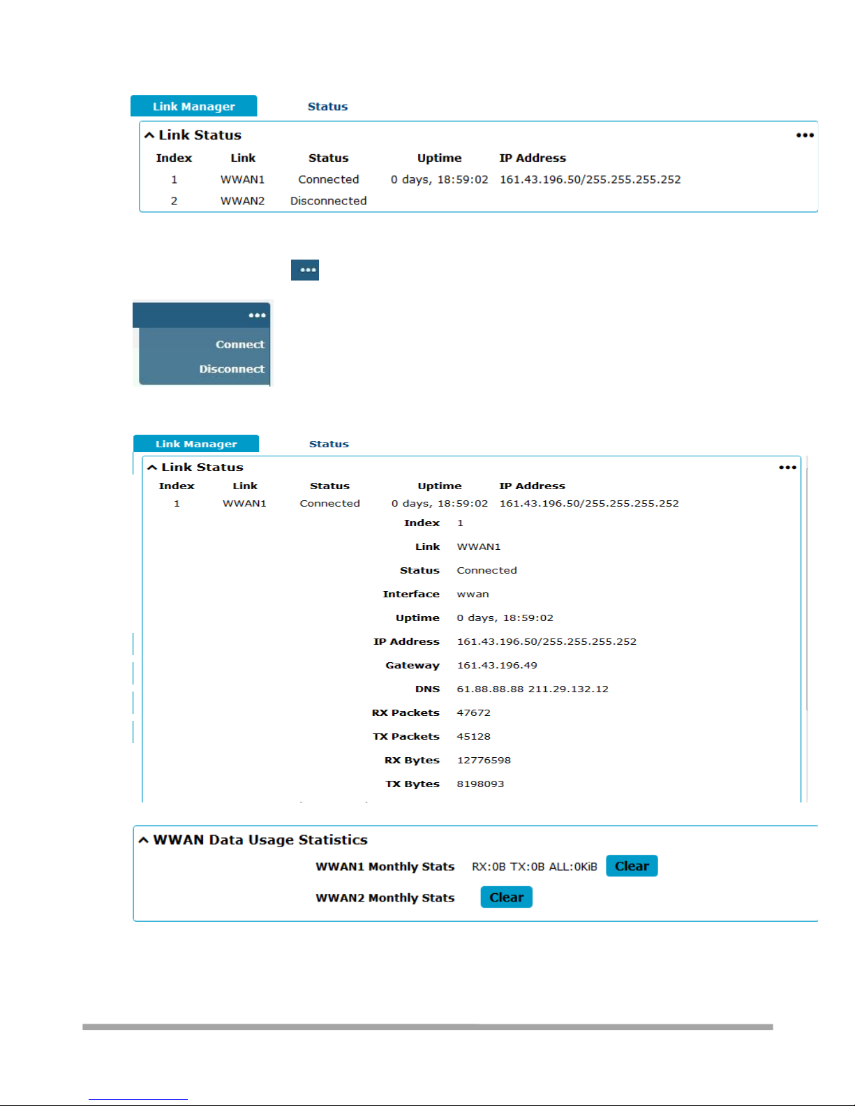
3.6.1.1 - Status
This page allows you to view the status of link connection and clear the monthly data usage
statistics.
Page 38
Multimax_user manual_v.4.0.4 July. 11, 2018 38/139
Confidential
Click the right-most button to select the connection status of the current link.
Click the row of the link, and it will show the details information of the current link connection
under the row.
Page 39
Multimax_user manual_v.4.0.4 July. 11, 2018 39/139
Confidential
Click the button to clear SIM1 or SIM2 monthly data traffic usage statistics. Data statistics
will be displayed only if enable the Data Allowance function in Interface > Link Manager > Link
Settings > WWAN Settings > Data Allowance.
3.6.2 - Interface > LAN
This section allows you to set the related parameters for LAN port. There are two LAN ports on
MULTIMAX Router, ETH0 and ETH1. You can create multiple, logical LAN port groups, called “lan0”,
“lan1” etc. You can use either ETH0 and ETH1 (or both!) as a LAN port, but at least one LAN port
must be assigned to logical group lan0. The default settings of ETH0 and ETH1 are part of group
lan0 and their default IP are 192.168.0.1/255.255.255.0.
(that is, default is two bridged Ethernet ports)
3.6.2.1 - LAN
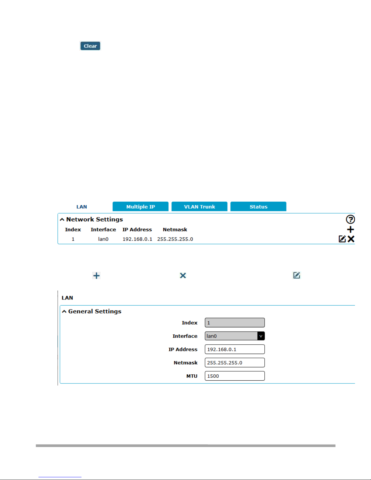
By default, there is a LAN port (lan0) in the list. To begin adding a new LAN port (lan1), please
configure ETH0 or ETH1 as lan1 first in Ethernet > Ports > Port Settings. Otherwise, the operation
will be prompted as “List is full”.
Note: Lan0 cannot be deleted.
You may click to add a new LAN port, or click to delete the current LAN port. Now, click to
edit the configuration of the LAN port. The maximum count is 2.
Page 40
Multimax_user manual_v.4.0.4 July. 11, 2018 40/139
Confidential
General Settings
Item
Description
Default
Index
List position – READ ONLY
--
Interface
Show the logical port group this setting applies to. Lan1 is available only if it
was selected by one of ETH0~ETH1 in Ethernet > Ports > Port Settings.
READ ONLY
--
IP Address
Set the IP address assigned to the logical LAN port group.
192.168.0.1
Netmask
Set the Netmask of the logical LAN port group.
255.255.255.0
MTU
Enter the Maximum Transmission Unit.
1500
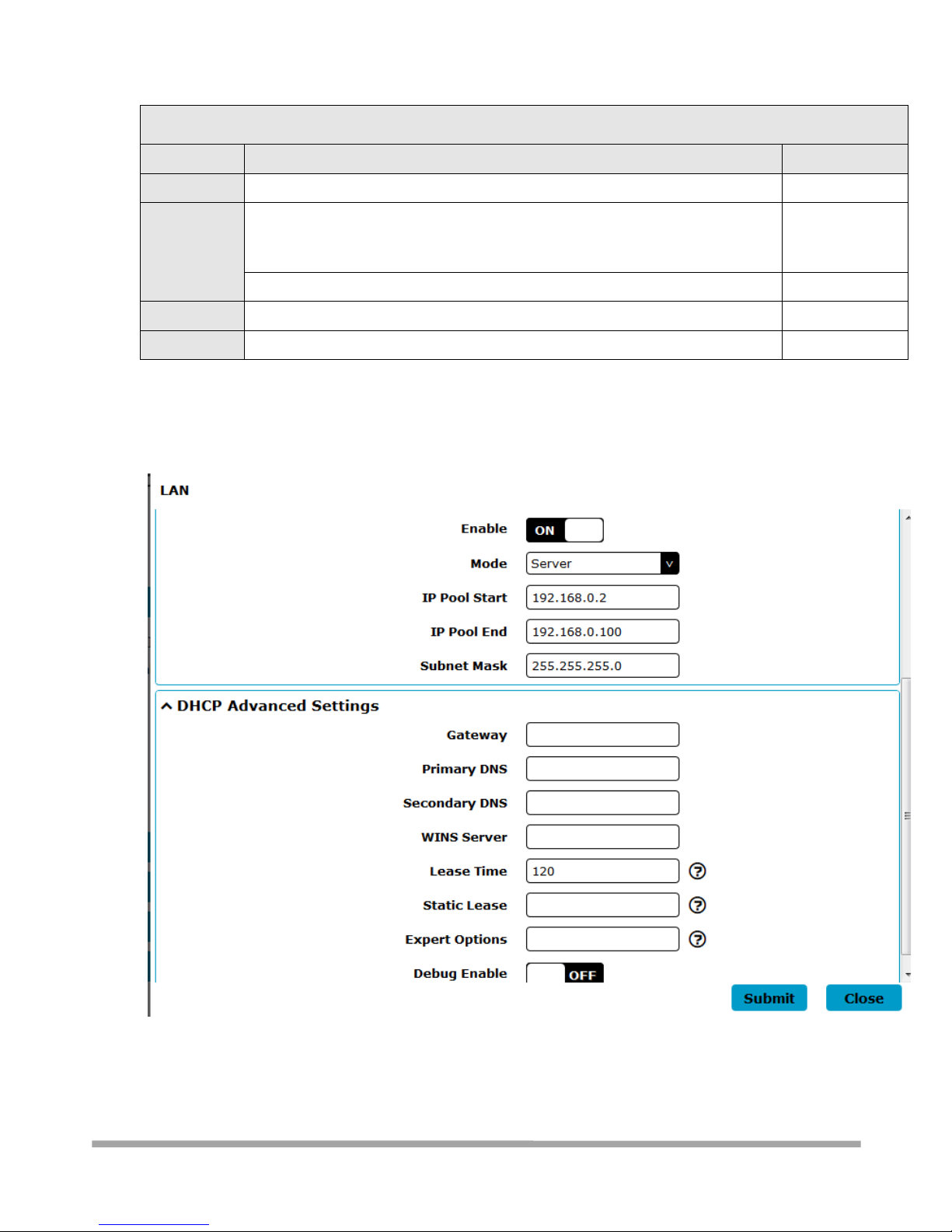
The window is displayed as below when choosing “Server” as the mode.
Page 41
Multimax_user manual_v.4.0.4 July. 11, 2018 41/139
Confidential
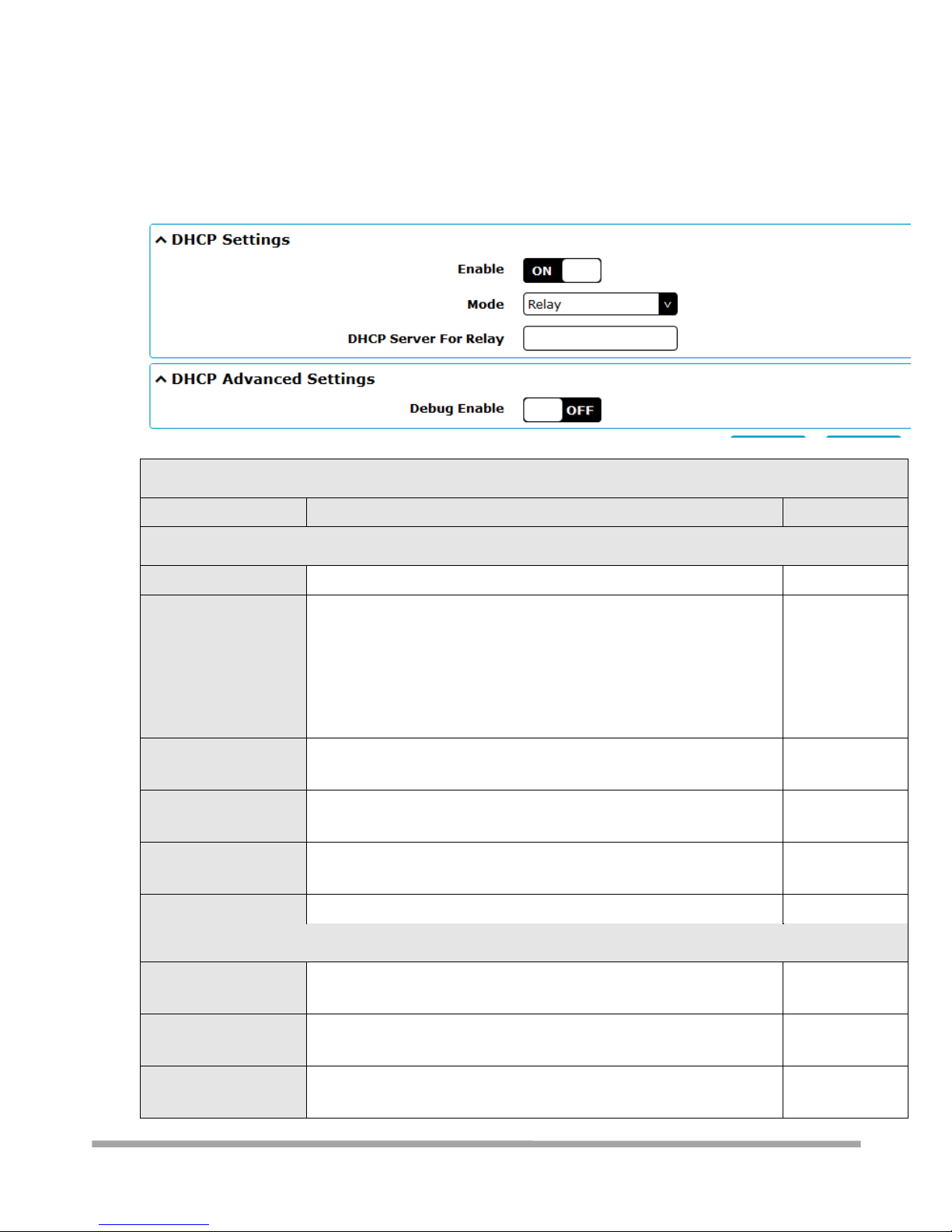
The window is displayed as below when choosing “Relay” as the mode.
LAN
Item
Description
Default
DHCP Settings
Enable
Click the toggle button to enable/disable the DHCP function.
ON
Mode
Select from “Server” or “Relay”.
Server: Lease IP address to DHCP clients which have been
connected to LAN port
Relay: Router can be DHCP Relay, which will provide a relay
tunnel to solve problem that DHCP Client and DHCP Server is not
in a same subnet
Server
IP Pool Start
Define the beginning of the pool of IP addresses which will be leased
to DHCP clients.
192.168.0.2
IP Pool End
Define the end of the pool of IP addresses which will be leased to
DHCP clients.
192.168.0.100
Subnet Mask
Define the subnet mask of IP address obtained by DHCP clients from
DHCP server.
255.255.255.0
DHCP Server for Relay
Enter the IP address of DHCP relay server.
Null
DHCP Advanced Settings
Gateway
Define the gateway assigned by the DHCP server to the clients, which
must be on the same network segment with DHCP address pool.
Null
Primary DNS
Define the primary DNS server assigned by the DHCP server to the
clients.
Null
Secondary DNS
Define the secondary DNS server assigned by the DHCP server to the
clients.
Null
Page 42
Multimax_user manual_v.4.0.4 July. 11, 2018 42/139
Confidential
WINS Server
Define the Windows Internet Naming Service obtained by DHCP
clients from DHCP sever.
Null
Lease Time
Set the lease time which the client can use the IP address obtained
from DHCP server, measured in seconds.
120
Static lease
Bind a lease to correspond an IP address via a MAC address.
format: mac,ip;mac,ip;..., e.g. FF:ED:CB:A0:98:01,192.168.0.200
Null
Expert Options
Enter some other options of DHCP server in this field.
format: config-desc;config-desc, e.g. log-dhcp;quiet-dhcp
Null
Debug Enable
Click the toggle button to enable/disable this option. Enable for DHCP
information output.
OFF
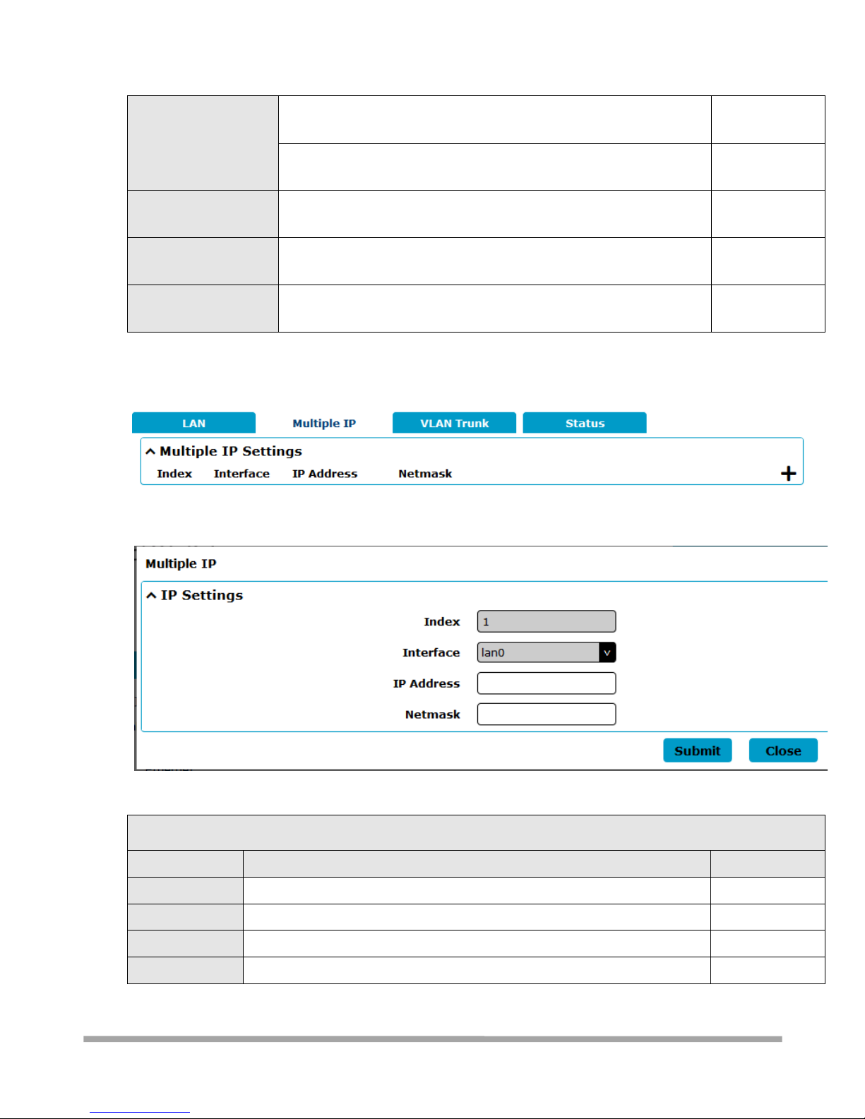
3.6.2.2 - Multiple IP
IP Settings
Item
Description
Default
Index
Entry position the list – READ ONLY
--
Interface
Logical LAN group – READ ONLY
--
IP Address
The additional IP address to be assigned to the LAN port group.
Null
Netmask
Set the Netmask for this IP.
Null
Page 43
Multimax_user manual_v.4.0.4 July. 11, 2018 43/139
Confidential
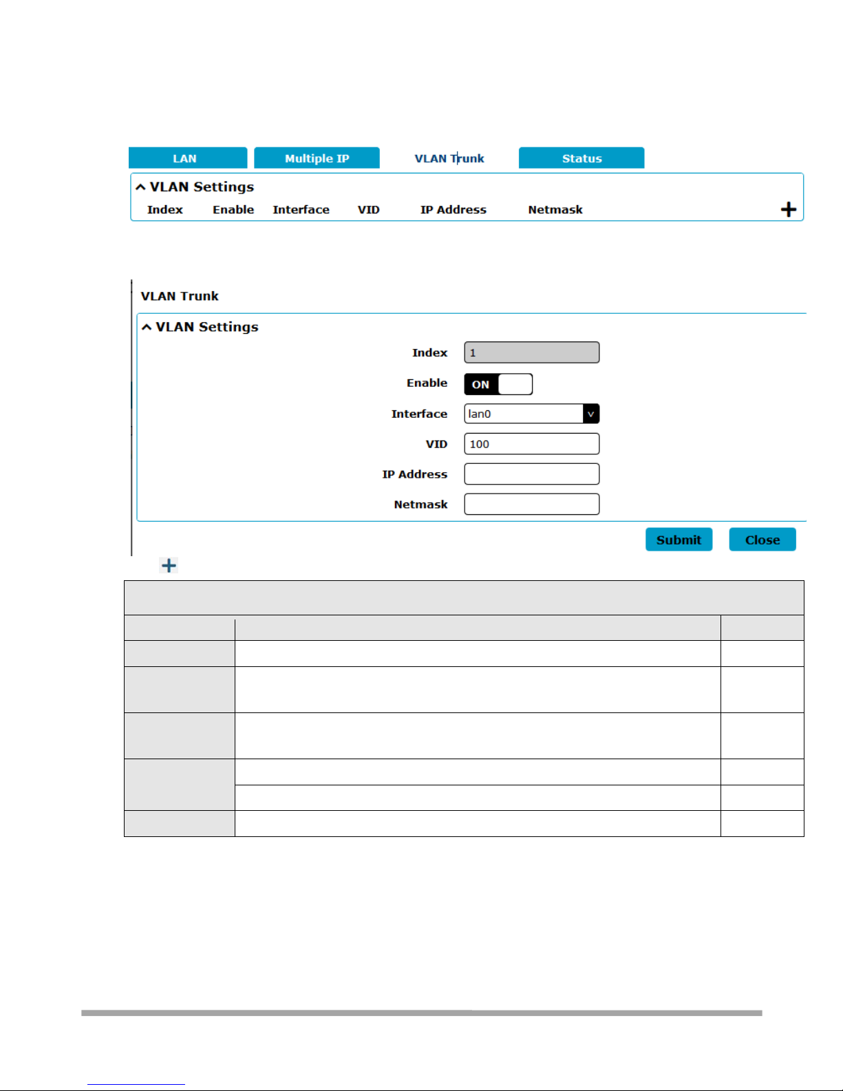
3.6.2.3 - VLAN Trunk
VLAN Trunk
Item
Description
Default
Index
Position in list – READ ONLY
--
Enable
Click the toggle button to enable/disable this VLAN tag. Enable to make router
encapsulate and de-encapsulate the VLAN tag.
ON
Interface
Choose the interface which wants to enable VLAN trunk function. Select from
“lan0” or “lan1” depends on your ETH0 and ETH1’s corresponding LAN port.
lan0
VID
Set the tag ID of VLAN and digits from 1 to 4094.
100
IP Address
Set the IP address of VLAN port.
Null
Netmask
Set the Netmask of VLAN port.
Null
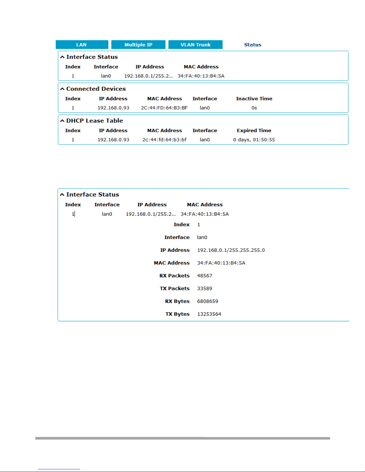
3.6.2.4 - Status
This section allows you to view the status of LAN connection.
Clic k to add a VLAN.
The maximum
count
is 8 .
Page 44
Multimax_user manual_v.4.0.4 July. 11, 2018 44/139
Confidential
By clicking on a row of the Interface Status area, detailed status information will be display under
the row. Please refer to the screenshot below.
3.6.4 - Interface > Ethernet
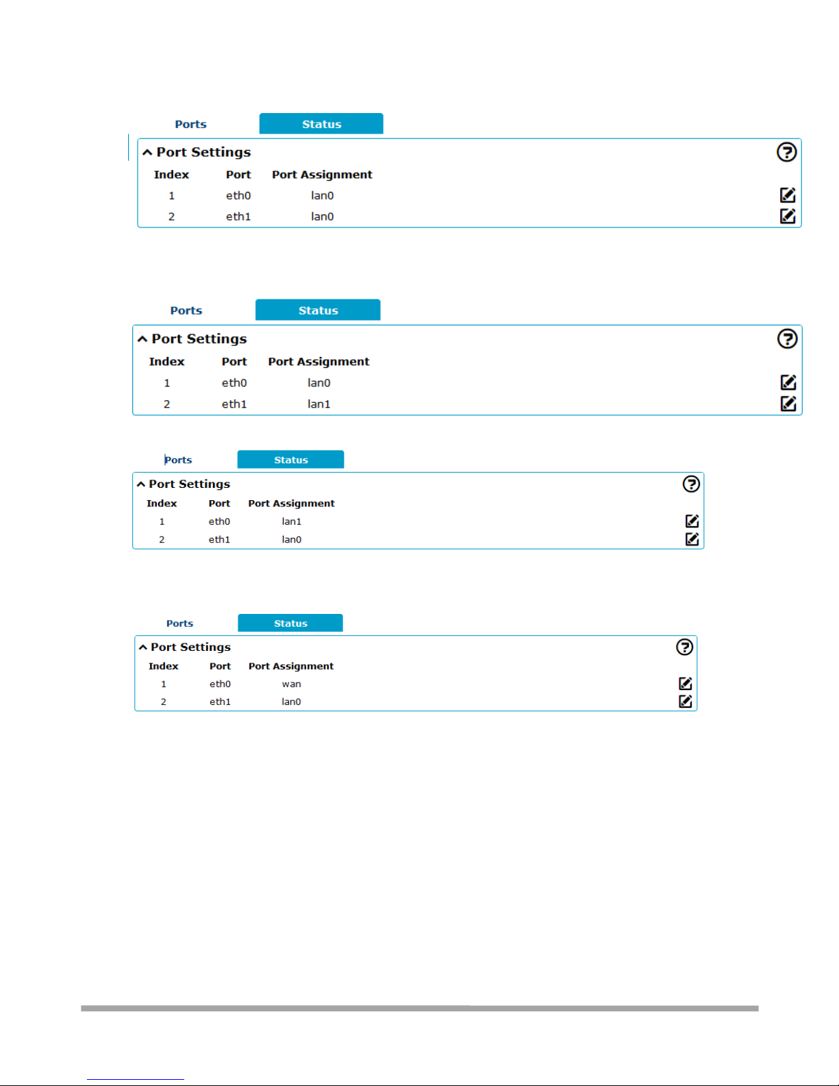
This section allows you to set the related parameters for Ethernet. There are two Ethernet ports on
MULTIMAX Router, ETH0 and ETH1. The ETH0 on the router can be configured as either a WAN or a
LAN port, while ETH1 can only be configured as a LAN port. By default, ETH0 and ETH1 are lan0, and
their IP are 192.168.0.1/255.255.255.0. Since lan0 must be assigned to one port and WAN port
must be assigned to the ETH0, there are four configurations. You can choose the appropriate
configuration to fit your current needs. The specific port configurations are shown below.
Page 45
Multimax_user manual_v.4.0.4 July. 11, 2018 45/139
Confidential
Bridge mode (both ETH ports on same subnet):
Routed mode (separate subnets for each ETH port):
Routed mode (same as previous, but logical to physical assignment is reversed):
Use a wired WAN:
Page 46
Multimax_user manual_v.4.0.4 July. 11, 2018 46/139
Confidential
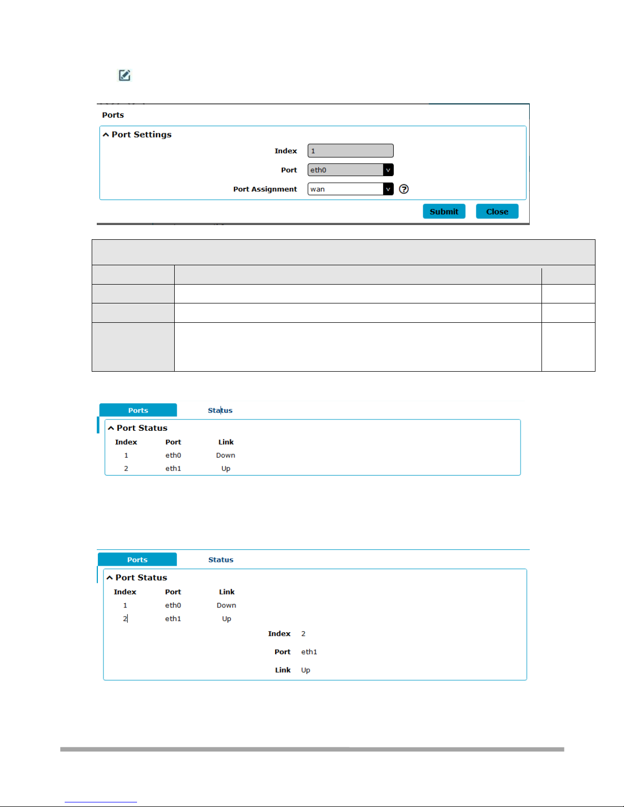
Click button of eth0 to configure its parameters. The port assignment can be changed by
selecting from the drop down list.
Port Settings
Item
Description
Default
Index
Indicate the ordinal of the list.
--
Port
Show the editing port, read only.
--
Port Assignment
Choose the Ethernet port’s type, as a WAN port or a LAN port. When setting the
port as a LAN port in Interface > LAN > LAN > Network Settings > General Settings,
you can click the drop-down list to select from “lan0” or “lan1”.
lan0
This column allows you to view the status of Ethernet port.
Click the row of status, the details status information will be display under the row. Please refer to
the screenshot below.
Page 47
Multimax_user manual_v.4.0.4 July. 11, 2018 47/139
Confidential
3.6.5 - Interface > Cellular
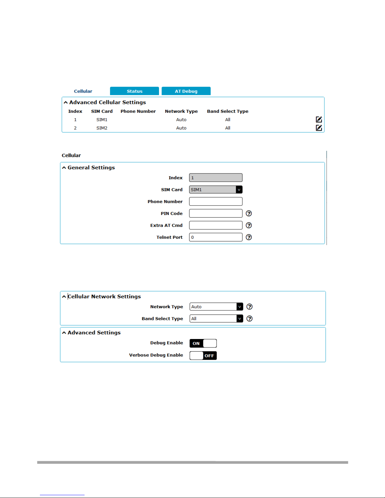
This section allows you to set the related parameters of Cellular. The MULTIMAX Router has two
SIM card slots, but do not support two SIM cards online simultaneously due to its single-module
design. If insert single SIM card at the first time, SIM1 slot and SIM2 slots are available.
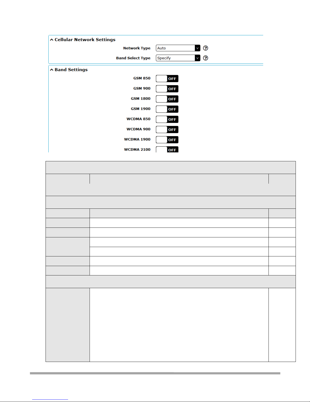
The window is displayed as below when choosing “Auto” as the network type.
The window is displayed as below when choosing “Specify” as the band select type.
Page 48
Multimax_user manual_v.4.0.4 July. 11, 2018 48/139
Confidential
Cellular
Item
Description
Default
General Settings
Cellular
Item
Description
Default
Index
Indicate the ordinal of the list.
--
SIM Card
Set the currently editing SIM card.
SIM1
Phone Number
Enter the phone number of the SIM card.
Null
PIN Code
Enter a 4-8 characters PIN code used for unlocking the SIM.
Null
Extra AT Cmd
Enter the AT commands used for cellular initialization.
Null
Telnet Port
Specify the Port listening of telnet service, used for AT over Telnet.
0
Cellular Network Settings
Network Type
Select from “Auto”, “2G Only”, “2G First”, “3G Only”, “3G First”, “4G Only”, “4G
First”.
Auto: Connect to the best signal network automatically
2G Only: Only the 2G network is connected
2G First: Connect to the 2G Network preferentially 3G Only: Only
the 3G network is connected
3G First: Connect to the 3G Network preferentially 4G Only: Only
the 4G network is connected
4G First: Connect to the 4G Network preferentially
Auto
Page 49
Multimax_user manual_v.4.0.4 July. 11, 2018 49/139
Confidential
Band Select Type
Select from “All” or “Specify”. You may choose certain bands if choosing
“Specify”.
All
Advanced Settings
Debug Enable
Click the toggle button to enable/disable this option. Enable for debugging
information output.
ON
Verbose Debug
Enable
Click the toggle button to enable/disable this option. Enable for verbose
debugging information output.
OFF
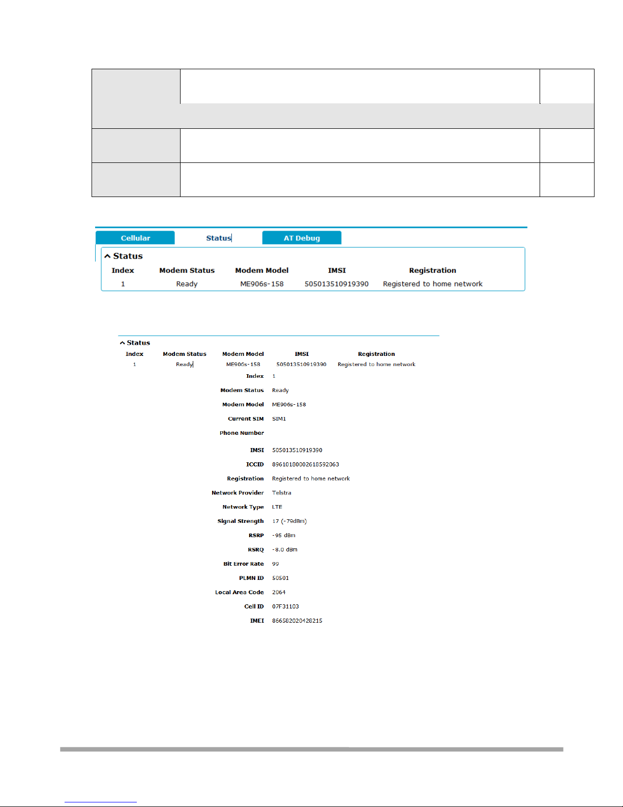
This section allows you to view the status of the cellular connection.
Click the row of status, the details status information will be displayed under the row.
Page 50
Multimax_user manual_v.4.0.4 July. 11, 2018 50/139
Confidential
Status
Item
Description
Index
Indicate the ordinal of the list.
Modem Status
Shows the status of the radio module.
Modem Model
Shows the model of the radio module.
Current SIM
Shows the SIM card that your router is using.
Phone Number
Shows the phone number of the current SIM.
Note: This option will be displayed if enter manually in Cellular > Advanced Cellular
Settings > SIM1/SIM2 > General Settings > Phone Number.
IMSI
Shows the IMSI number of the current SIM.
ICCID
Shows the ICCID number of the current SIM.
Registration
Shows the current network status.
Network Provider
Shows the name of Network Provider.
Network Type
Shows the current network service type, e.g. GPRS.
Signal Strength
Shows the signal strength detected by the mobile.
Bit Error Rate
Shows the current bit error rate.
PLMN ID
Shows the current PLMN ID.
Local Area Code
Shows the current local area code used for identifying different area.
Status
Item
Description
Cell ID
Shows the current cell ID used for locating the router.
IMEI
Shows the IMEI (International Mobile Equipment Identity) number of the radio
module.
Firmware Version
Shows the current firmware version of the radio module.
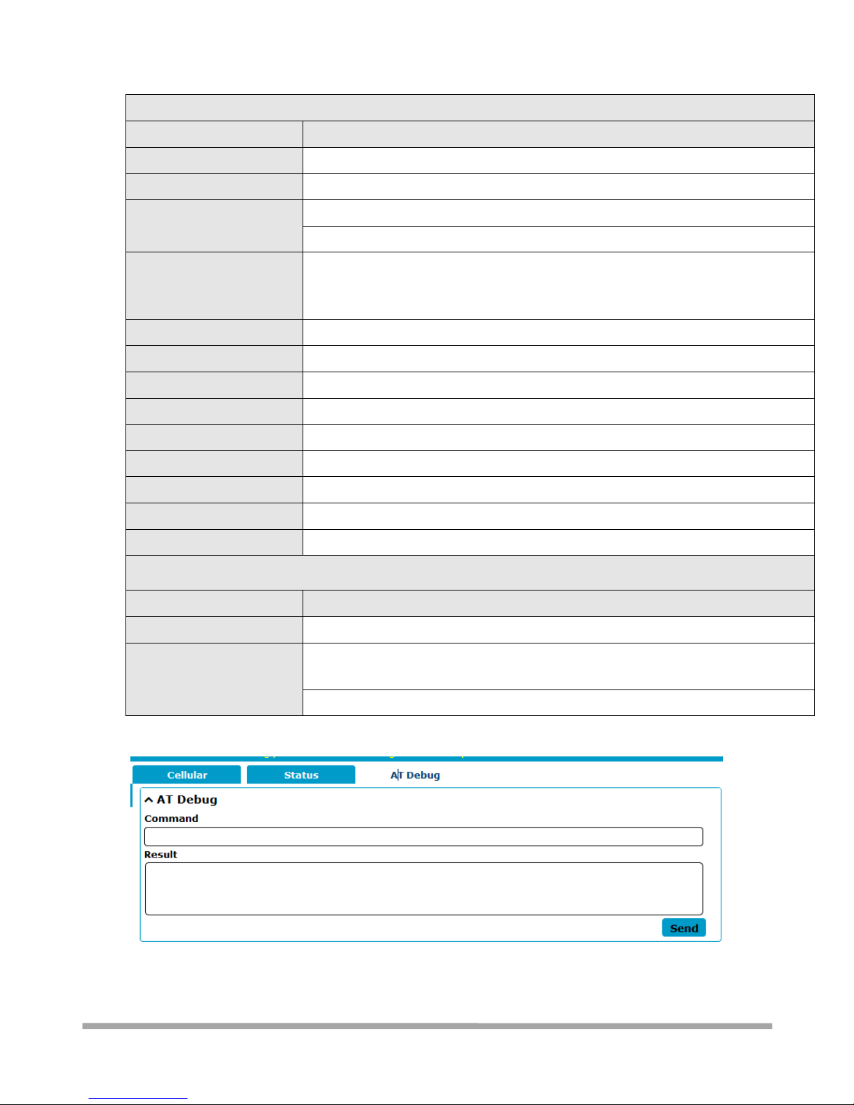
This page allows you to check the AT Debug.
Page 51
Multimax_user manual_v.4.0.4 July. 11, 2018 51/139
Confidential
AT Debug
Item
Description
Default
Command
Enter the AT command that you want to send to cellular module in this
text box.
Null
Result
Show the AT command responded by cellular module in this text box.
Null
Click the button to send AT command.
--
3.6.6 - Interface > USB
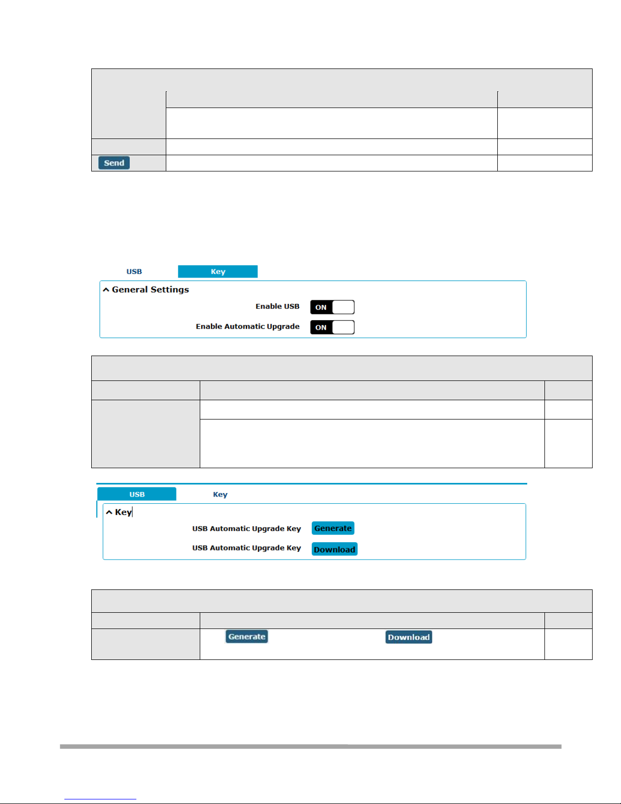
This section allows you to set the USB parameters. The USB interface of the router can be used for
firmware upgrade and configuration upgrade.
General Settings @ USB
Item
Description
Default
Enable USB
Click the toggle button to enable/disable the USB option.
ON
Enable Automatic
Firmware Updating
Click the toggle button to enable/disable this option. Enable to automatically
update the firmware of the router when inserting a USB storage device with a
router firmware.
ON
Router has the key for USB automatic update. User can generate the key in this page.
Key
Item
Description
Default
USB Automatic Update
Key
Click to generate a key, and click to download the key.
--
Page 52
Multimax_user manual_v.4.0.4 July. 11, 2018 52/139
Confidential
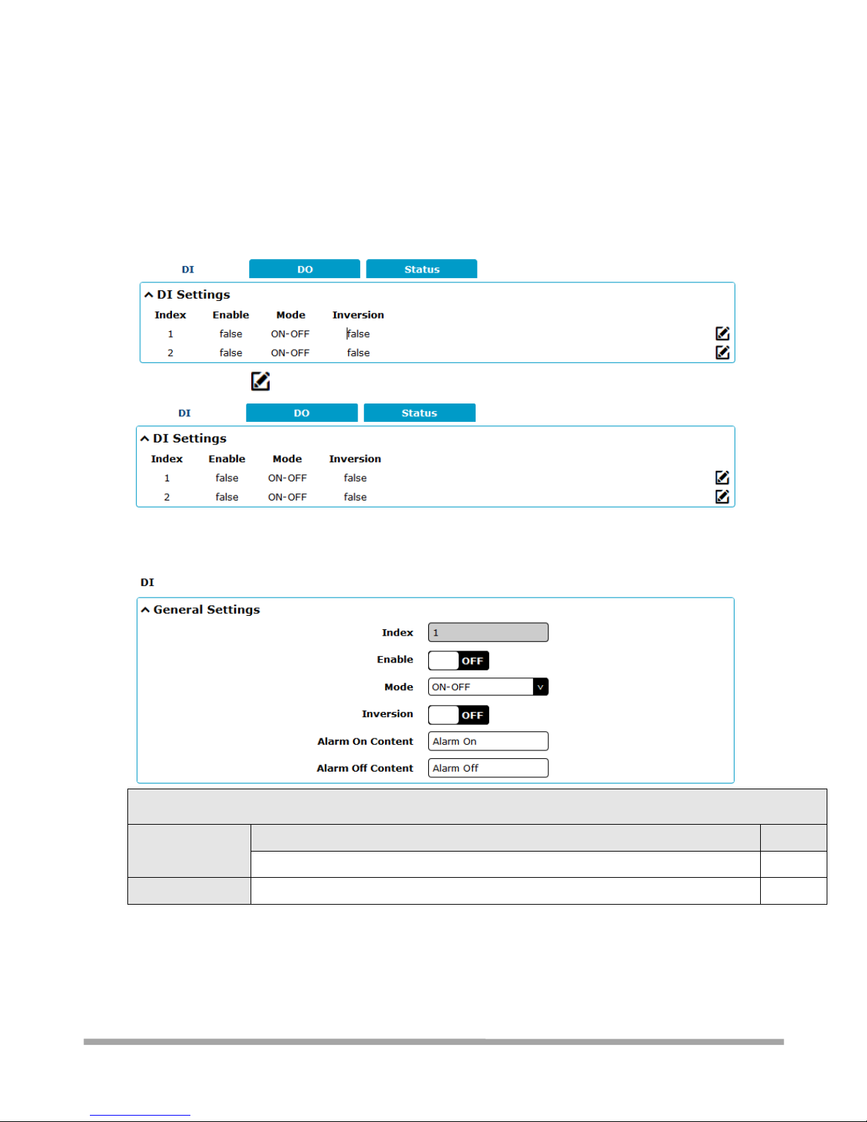
3.6.7 - Interface > DI/DO
This section allows you to set the DI/DO parameters. Digital Input and Digital Output are the
specific interfaces for MULTIMAX. The DI interface can be used for triggering alarm, while the DO
can be used for controlling the slave device so as to realize real-time monitoring.
3.6.7.1 - DI
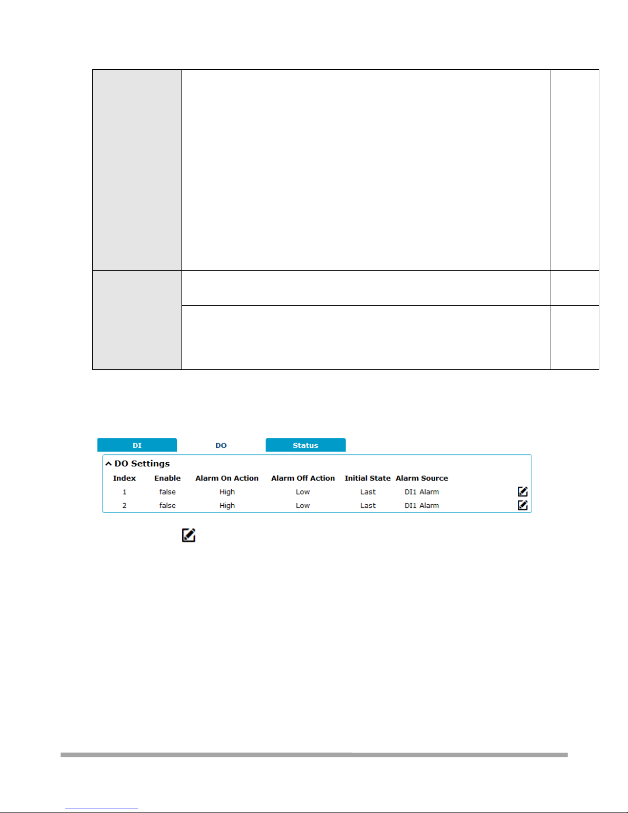
Click the right-most button of index as shown. The default mode is “ON-OFF”
The window is displayed as below when choosing “Counter” as the mode.
General Settings @ DI
Item
Description
Default
Index
Indicate the ordinal of the list.
--
Enable
Click the toggle button to enable/disable this DI.
OFF
Page 53
Multimax_user manual_v.4.0.4 July. 11, 2018 53/139
Confidential
Mode
Select from “ON-OFF” or “Counter”.
ON-OFF: DI interface support ON and OFF mode (high or low level electrical)
trigger DI alarm. The mode default to ON, and OFF mode is available only
when enabling the inversion feature
ON—Under this mode, DI alarm status will be triggered to ON when DI
interface open from GND or input a high level electrical (logic 1), on the
contrary DI alarm status will be trigged to OFF when DI interface connect to
GND or input a low level electrical (logic 0)
OFF—Under this mode, DI alarm status will be triggered to ON when DI
interface connect to GND or input a low level electrical (logic 0), on the
contrary DI alarm status will be trigged to OFF when DI interface open from
GND or input a high level electrical (logic 1)
Counter: Event counter mode
ON-OFF
Inversion
Click the toggle button to enable/disable this option. Enable to set DI mode as OFF
mode.
OFF
Threshold Value
Set the threshold vale. It will trigger alarm when event counter reaches this figure.
After triggering alarm, DI will keep counting but not trigger alarm again. Enter 0 to
65535 digits. (0=will not trigger alarm)
Note: This option is only available when DI under the “Counter” mode.
Null
Note: It defaults as high alarm, while turns to low alarm after enabling the “Inversion” button.
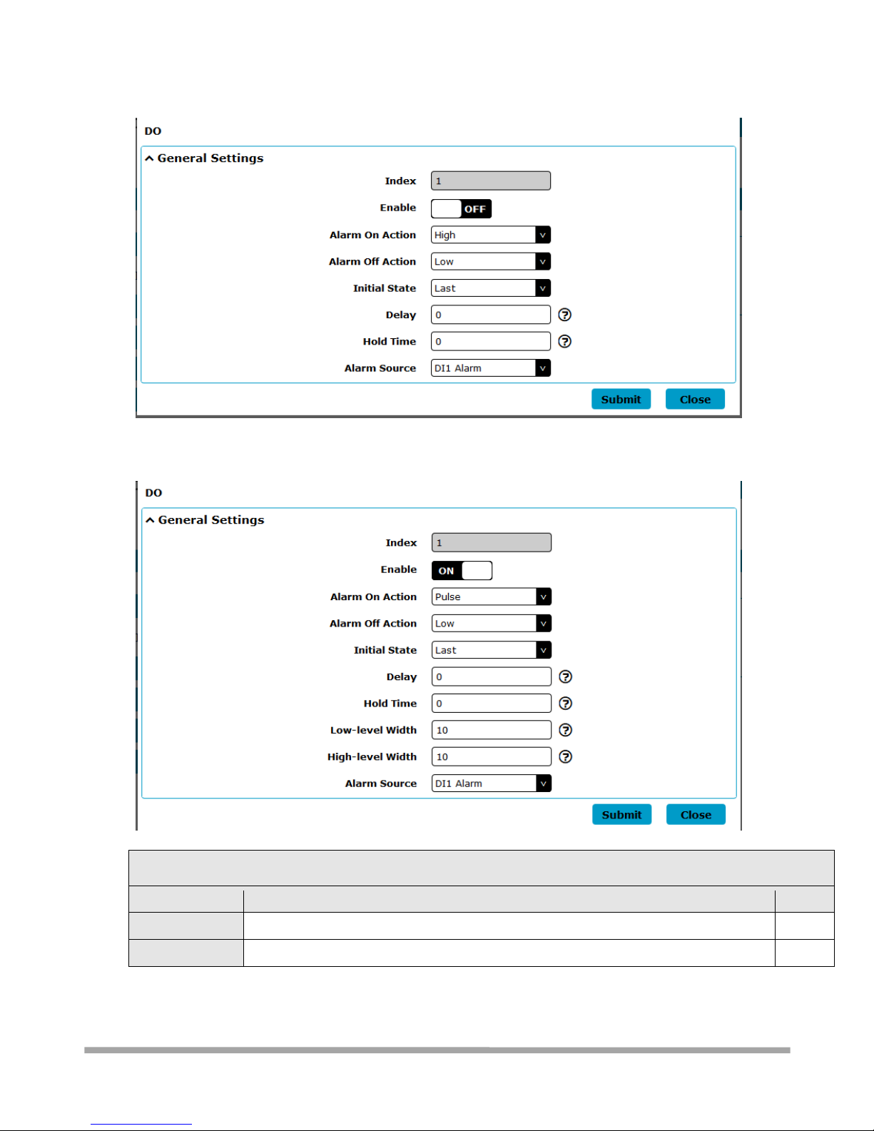
3.6.7.2 - DO
Click the right-most to enter the DO configuration
Page 54
Multimax_user manual_v.4.0.4 July. 11, 2018 54/139
Confidential
The window is displayed as below when choosing “Pulse” as the alarm on action.
The window is displayed as below when choosing “Pulse” as the alarm off action.
DO
Item
Description
Default
Index
Indicate the ordinal of the list.
--
Enable
Click the toggle button to enable/disable this DO.
OFF
Page 55

Multimax_user manual_v.4.0.4 July. 11, 2018 55/139
Confidential
Alarm On Action
Digital Output initiates when there is an alarm. Selected from “High”, “Low” or
“Pulse”.
High: a high electrical level output
Low: a low electrical level output
Pulse: Generates a square wave as specified in the pulse mode parameters when
triggered
High
Alarm Off
Action
Digital Output initiates when alarm removed. Selected from “High”, “Low” or “Pulse”.
High: a high electrical level output
Low: a low electrical level output
Pulse: Generates a square wave as specified in the pulse mode parameters when
triggered
Low
Initial State
Specify the Digital Output status when powered on. Selected from “Last”, “High” or
“Low”.
Last: DO’s status will consist with the status of last power off
High: DO interface is in high electrical level
Low: DO interface is in low electrical level
Low
Delay
Set the delay time for DO alarm start-up. The first pulse will be generated after a
“Delay”. Enter from 0 to 30000ms. (0=generate pulse without delay)
0
Hold Time
Set the hold time of DO status (Alarm On Action/Alarm Off Action). When the action
time reach this specified time, DO will stop the action. Enter from 0 to 255 seconds.
(0=keep on until the next action)
0
Low-level Width
Set the low-level width. It is available when enabling Pulse as “Alarm On Action/Alarm
Off Action”. In Pulse Output mode, the selected digital output channel will generate a
10
DO
Item
Description
Default
square wave as specified in the pulse mode parameters. The low level widths are
specified here. Enter from 1 to 30000 ms.
High-level
Width
Set the high-level width. It is available when enabling Pulse as “Alarm On
Action/Alarm Off Action”. In Pulse Output mode, the selected digital output channel
will generate a square wave as specified in the pulse mode parameters. The high level
widths are specified here. Enter from 1 to 30000 ms.
10
Alarm Source
Digital Output initiates according to different alarm source. Selected from “DI1
Alarm”, “DI2 Alarm”. DI1/DI2 Alarm: Digital Output triggers the related action when
there is alarm from Digital Input.
DI1
Alarm
Page 56
Multimax_user manual_v.4.0.4 July. 11, 2018 56/139
Confidential
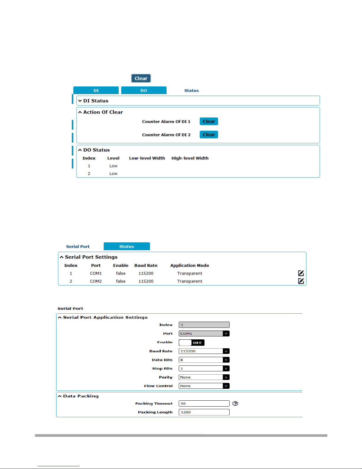
3.6.7.3 - Status
This window allows you to view the status of DO and DI interface. It also can clear the counter
alarm of DI in here. button to clear DI1 or DI2 monthly usage statistics info for counter
a
l
a
r
m
.
3.6.8 - Interface > Serial Port
This section allows you to set the serial port parameters. MULTIMAX Router supports one COM1
and one COM2, also can be configured as either two COM1 or two COM2.
Click the edit button of COM1.
Clic
k
Page 57
Multimax_user manual_v.4.0.4 July. 11, 2018 57/139
Confidential
Serial Port
Item
Description
Default
Serial Port Application Settings
Index
Indicate the ordinal of the list.
--
Port
Show the current serial’s name, read only.
--
Enable
Click the toggle button to enable/disable this serial port. When the status is OFF,
the serial port is not available.
OFF
Baud Rate
Select from “300”, “600”, “1200”, “2400”, “4800”, “9600”, “19200”, “38400”,
“57600” , “115200” or “230400”.
115200
Data Bits
Select from “7” or “8”.
8
Stop Bits
Select from “1” or “2”.
1
Parity
Select from “None”, “Odd” or “Even”.
None
Flow control
Select from “None”, “Software” or “Hardware”.
None
Data Packing
Packing Timeout
Set the packing timeout. The serial port will queue the data in the buffer and
send the data to the Cellular WAN/Ethernet WAN when it reaches the Interval
Timeout in the field.
Note: Data will also be sent as specified by the packet length even when data is
not reaching the interval timeout in the field.
50
Packing Length
Set the packet length. The Packet length setting refers to the maximum amount
of data that is allowed to accumulate in the serial port buffer before sending.
When a packet length between 1 and 3000 bytes is specified, data in the buffer
will be sent as soon it reaches the specified length.
1200
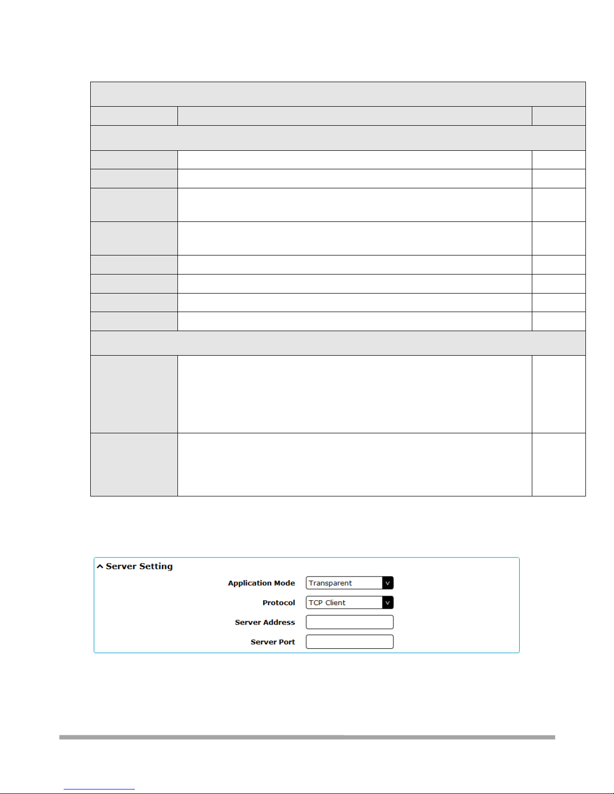
The window is displayed as below when choosing “Transparent” as the application mode and
“TCP Client” as the protocol.
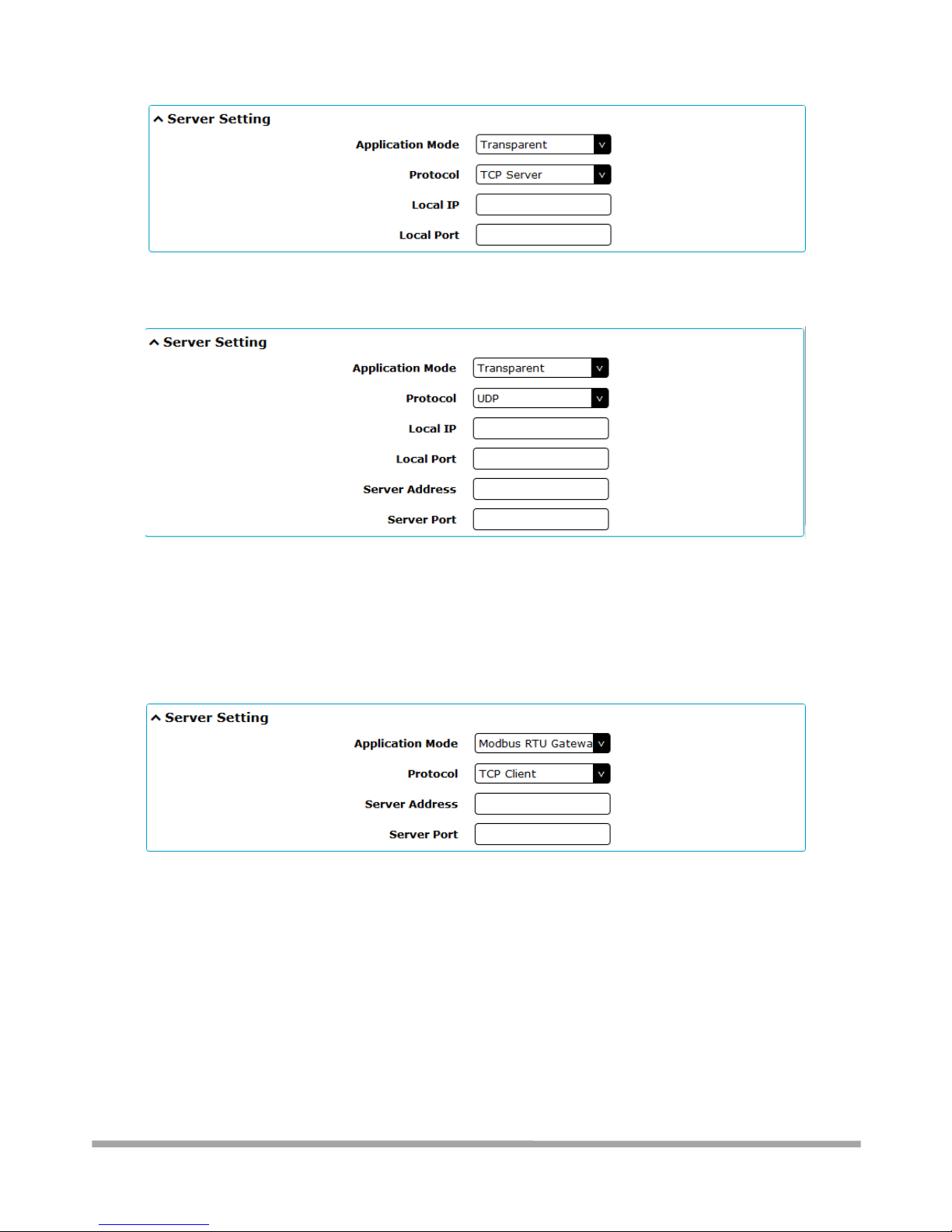
The window is displayed as below when choosing “Transparent” as the application mode and
“TCP Server” as the protocol.
Page 58
Multimax_user manual_v.4.0.4 July. 11, 2018 58/139
Confidential
The window is displayed as below when choosing “Transparent” as the application mode and
“UDP” as the protocol.
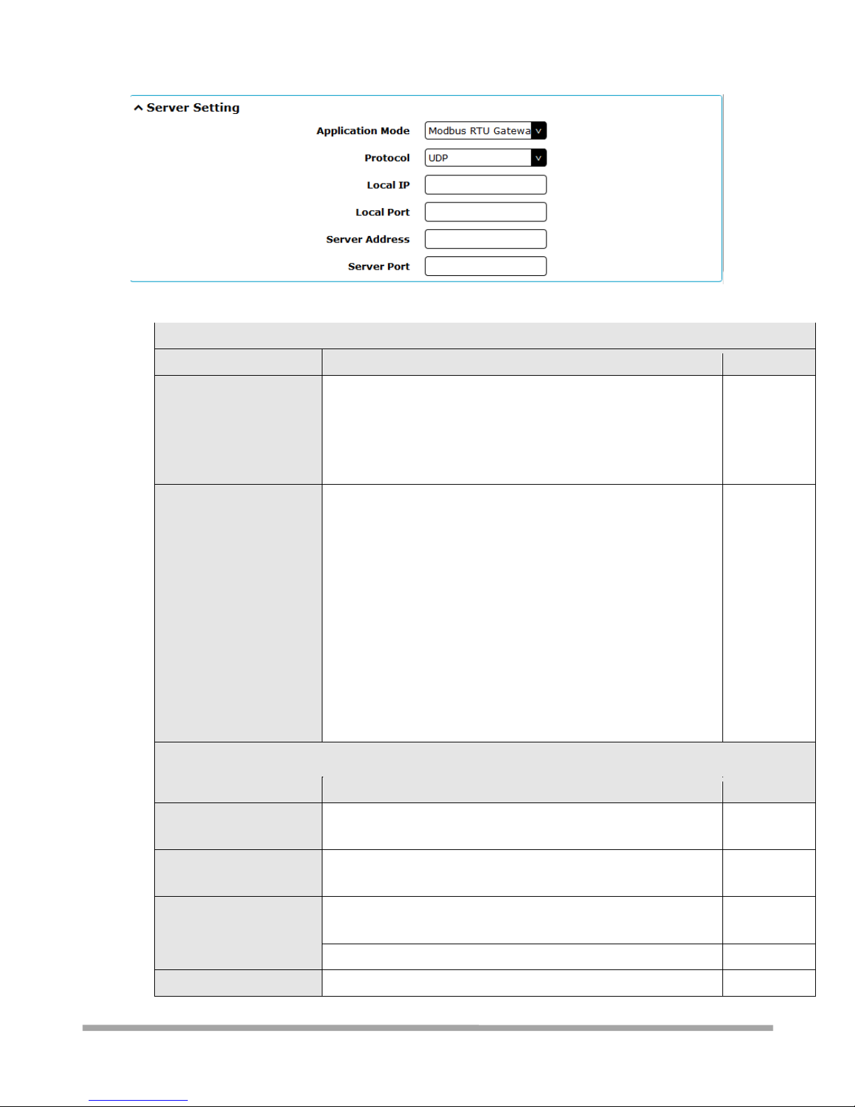
The window is displayed as below when choosing “Modbus RTU Gateway” as the application
mode and “TCP Client” as the protocol.
The window is displayed as below when choosing “Modbus RTU Gateway” as the application
mode and “TCP Server” as the protocol.
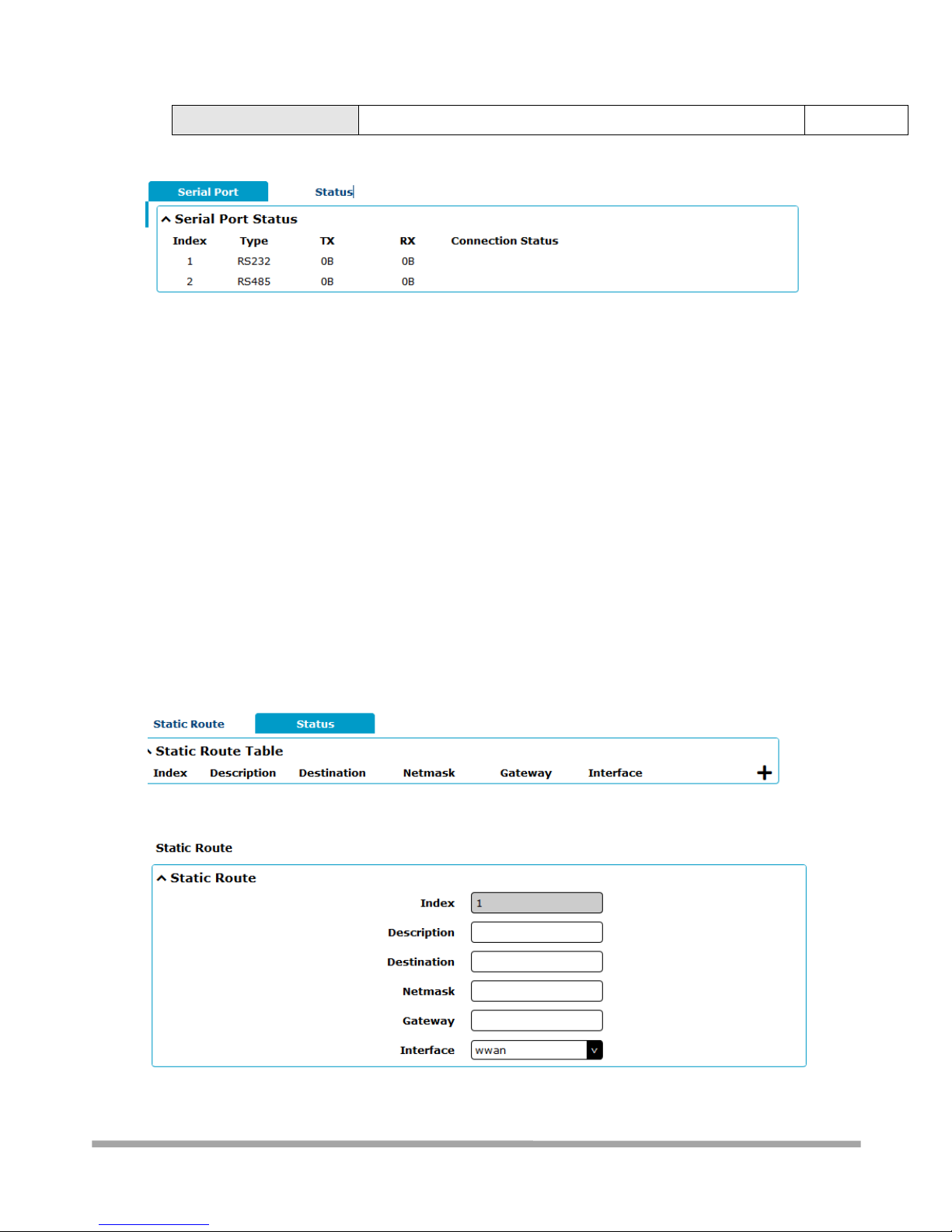
The window is displayed as below when choosing “Modbus RTU Gateway” as the application
mode and “UDP” as the protocol.
Page 59
Multimax_user manual_v.4.0.4 July. 11, 2018 59/139
Confidential
Server Settings
Item
Description
Default
Application Mode
Select from “Transparent” or “Modbus RTU Gateway”.
Transparent: Router will transmit the serial data
transparently
Modbus RTU Gateway: Router will translate the Modbus RTU
data to Modbus TCP data and sent out, and vice versa
Transparent
Protocol
Select from “TCP Client”, “TCP Server”, “UDP” or “Robustlink”.
TCP Client: Router works as TCP client, initiate TCP
connection to TCP server. Server address supports both IP
and domain name
TCP Server: Router works as TCP server, listening for
connection request from TCP client
UDP: Router works as UDP client
Robustlink: Router will automatically upload the serial data
to Robustlink platform under the Robustlink protocol.
Robustlink is a management platform from Robustel. This
function only available when Router is connects to
Robustlink
TCP Client
Server Settings
Item
Description
Default
Server Address
Enter the address of server which will receive the data sent from
router’s serial port. IP address or domain name will be available.
Null
Server Port
Enter the specified port of server which is used for receiving the
serial data.
Null
Local IP @ Transparent
Enter router’s LAN IP which will forward to the internet port of
router.
Null
Local Port @ Transparent
Enter the port of router’s LAN IP.
Null
Local IP @ Modbus
Enter the local IP of under Modbus mode.
Null
Page 60
Multimax_user manual_v.4.0.4 July. 11, 2018 60/139
Confidential
Local Port @ Modbus
Enter the local port of under Modbus mode.
Null
Click the “Status” column to view the current serial port type.
3.7 – Network
3.7.1 - Network > Route
This section allows you to set the static route. Static route is a form of routing that occurs when a
router uses a manually-configured routing entry, rather than information from a dynamic routing
traffic. Route Information Protocol (RIP) is widely used in small network with stable use rate. Open
Shortest Path First (OSPF) is made router within a single autonomous system and used in large
network.
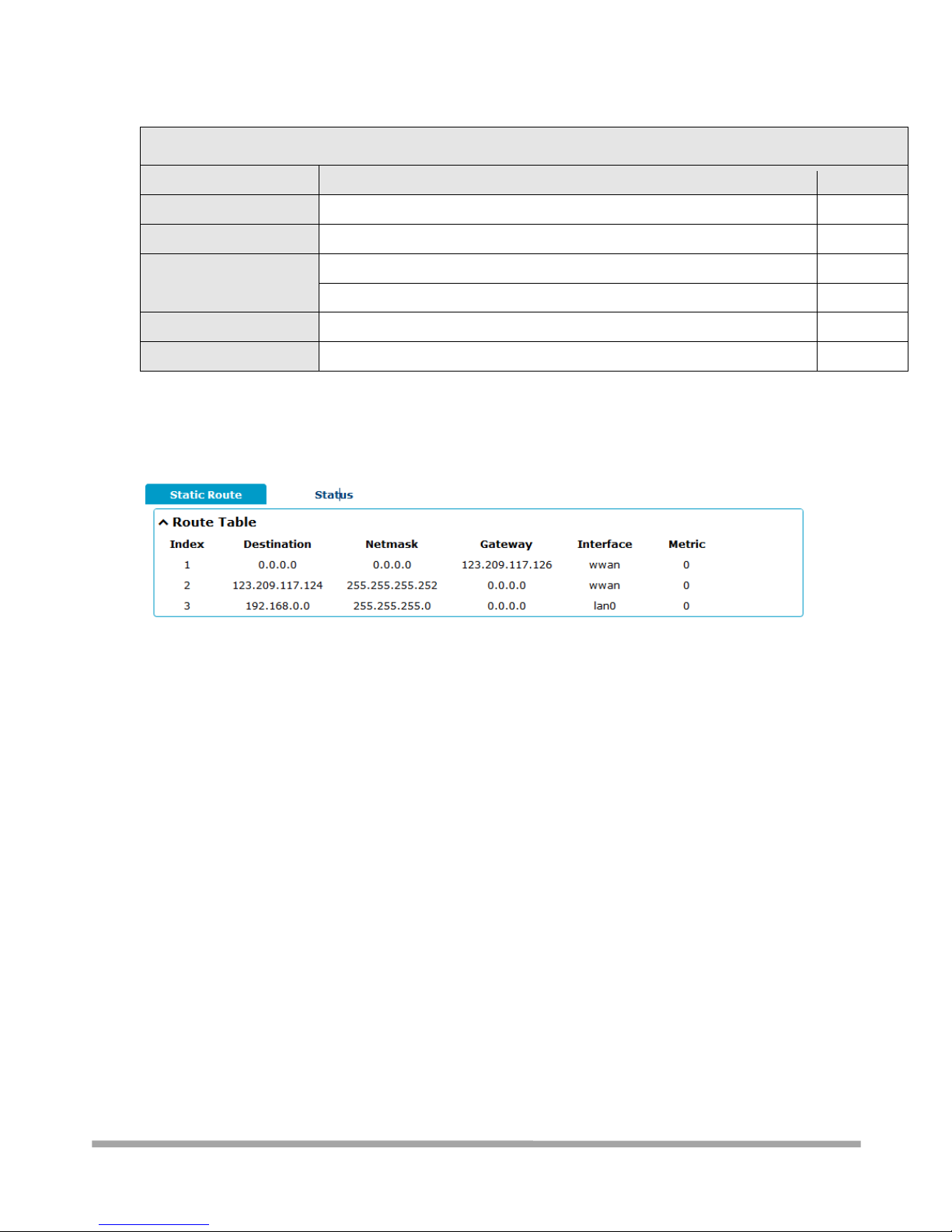
3.7.1.1 – Static Route
Click + to add Static Route. The windows will appear as below. Configure the static route according
Page 61
Multimax_user manual_v.4.0.4 July. 11, 2018 61/139
Confidential
Static Route
Item
Description
Default
Index
Indicate the ordinal of the list.
--
Description
Enter a description for this route.
Null
Destination
Enter the IP address of destination host or destination network.
Null
Netmask
Enter the Netmask of destination host or destination network.
Null
Gateway
Define the gateway of the destination.
Null
Interface
Choose the corresponding port of the link that you want to configure.
wwan
3.7.1.2 - Status
This window allows you to view the status of route.
3.7.2 - Network > Firewall
This section allows you to set the firewall and its related parameters, including Filtering, Port
Mapping and DMZ.
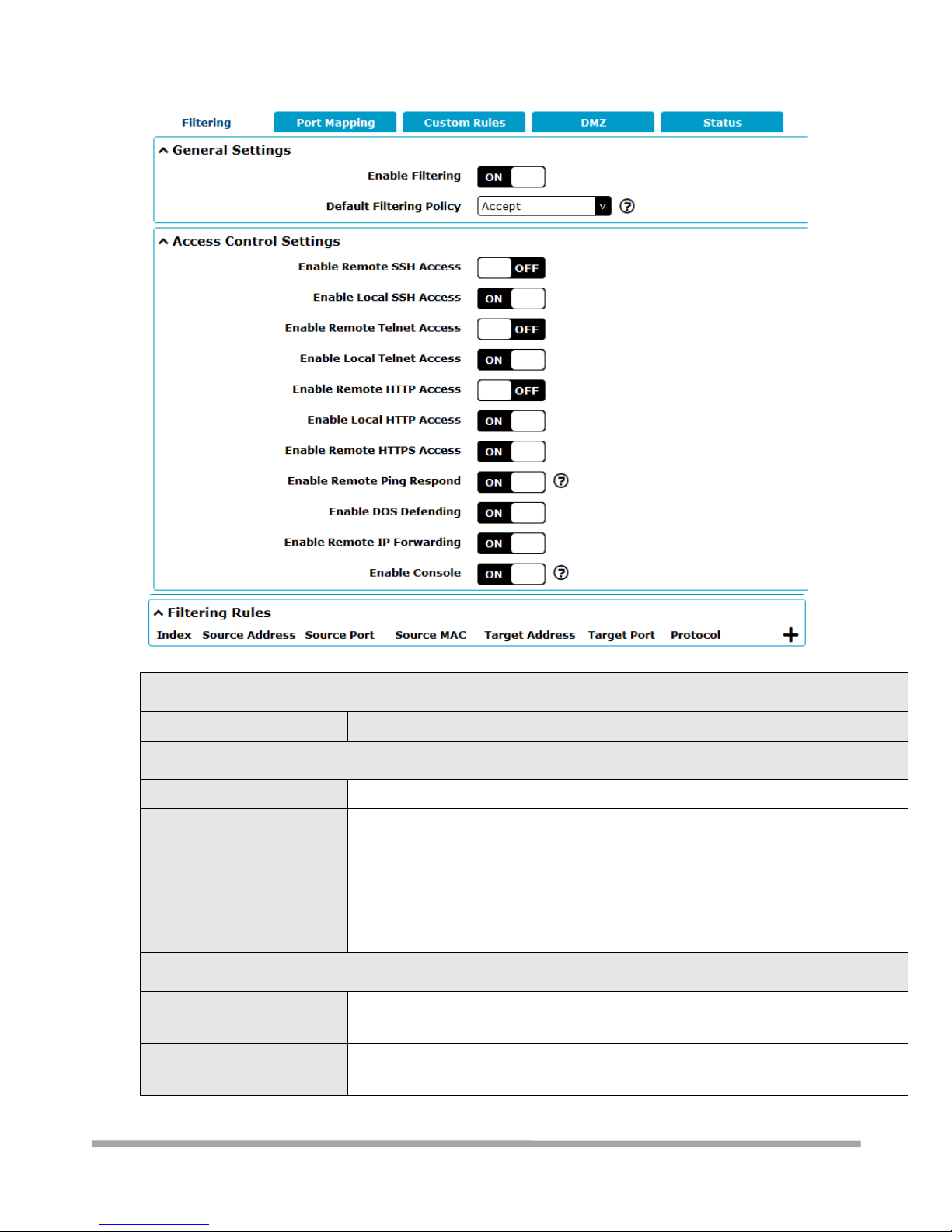
3.7.2.1 - Filtering
The filtering rules can be used to either accept or block certain users or ports from accessing your
router.
Page 62
Multimax_user manual_v.4.0.4 July. 11, 2018 62/139
Confidential
Filtering
Item
Description
Default
General Settings
Enable Filtering
Click the toggle button to enable/disable the filtering option.
ON
Default Filtering Policy
Select from “Accept” or “Drop”. Cannot be changed when filtering rules
table is not empty.
Accept: Router will accept all the connecting requests except the
hosts which fit the drop filter list
Drop: Router will drop all the connecting requests except the hosts
which fit the accept filter list
Accept
Access Control Settings
Enable Remote SSH Access
Click the toggle button to enable/disable this option. When enabled,
the Internet user can access the router remotely via SSH.
OFF
Enable Local SSH Access
Click the toggle button to enable/disable this option. When enabled,
the LAN user can access the router locally via SSH.
ON
Page 63
Multimax_user manual_v.4.0.4 July. 11, 2018 63/139
Confidential
Enable Remote Telnet Access
Click the toggle button to enable/disable this option. When enabled,
the Internet user can access the router remotely via Telnet.
OFF
Enable Local Telnet Access
Click the toggle button to enable/disable this option. When enabled,
the LAN user can access the router locally via Telnet.
ON
Enable Remote HTTP Access
Click the toggle button to enable/disable this option. When enabled,
the Internet user can access the router remotely via HTTP.
OFF
Enable Local HTTP Access
Click the toggle button to enable/disable this option. When enabled,
the LAN user can access the router locally via HTTP.
ON
Enable Remote HTTPS Access
Click the toggle button to enable/disable this option. When enabled,
the Internet user can access the router remotely via HTTPS.
ON
Enable Remote Ping Respond
Click the toggle button to enable/disable this option. When enabled,
the router will reply to the Ping requests from other hosts on the
Internet.
ON
Enable DOS Defending
Click the toggle button to enable/disable this option. When enabled,
the router will defend the DOS. Dos attack is an attempt to make a
machine or network resource unavailable to its intended users.
ON
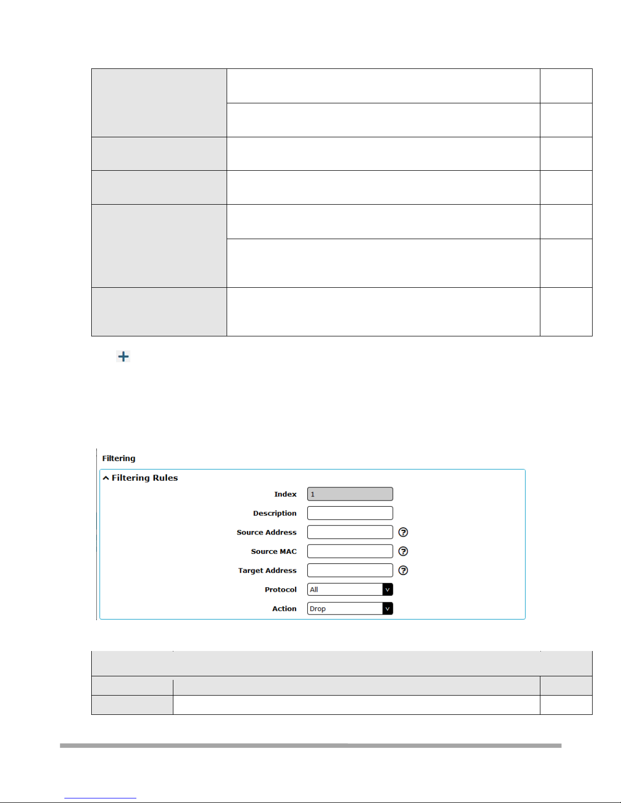
Click to add filtering rule. The maximum count is 20. The window is displayed as below when
defaulting “All” or choosing “ICMP” as the protocol. Here take “All” as an example.
The window is displayed as below when choosing “TCP”, “UDP” or “TCP-UDP” as the protocol. Here
take “TCP” as an example.
Filtering Rules
Item
Description
Default
Index
Indicate the ordinal of the list.
--
Page 64
Multimax_user manual_v.4.0.4 July. 11, 2018 64/139
Confidential
Description
Enter a description for this filtering rule.
Null
Source Address
Defines if access is allowed from one or a range of IP addresses which are defined
by Source IP Address, or every IP addresses.
Null
Source Port
Specify an access originator and enter its source port.
Null
Source MAC
Enter the MAC address of the defined source IP address.
Null
Target Address
Defines if access is allowed to one or a range of IP addresses which are defined by
Target IP Address, or every IP addresses.
Null
Target Port
Enter the target port which the access originator wants to access.
Null
Filtering Rules
Item
Description
Default
Protocol
Select from “All”, “TCP”, “UDP”, “ICMP” or “TCP-UDP”.
Note: It is recommended that you choose “All” if you don’t know which protocol of
your application to use.
All
Action
Select from “Accept” or “Drop”.
Accept: When Default Filtering Policy is drop, router will drop all the
connecting requests except the hosts which fit this accept filtering list
Drop: When Default Filtering Policy is accept, router will accept all the
connecting requests except the hosts which fit this drop filtering list
Drop
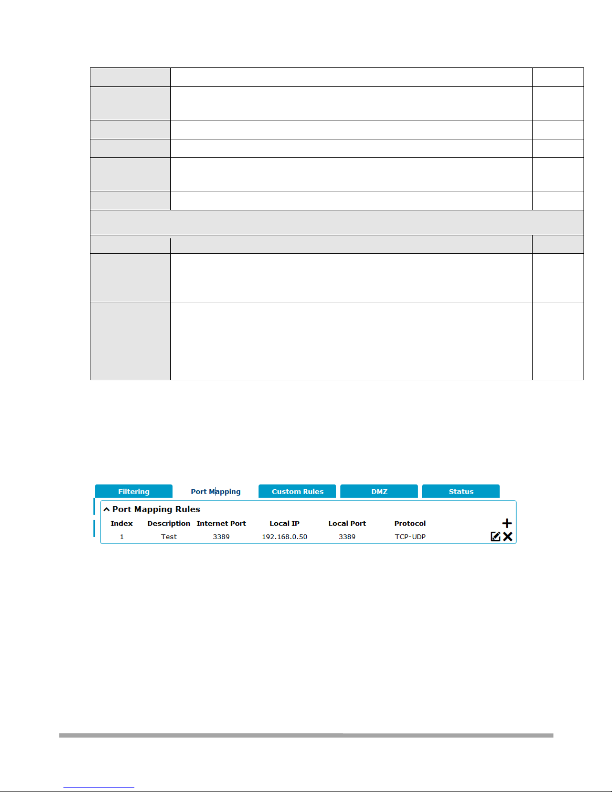
3.7.2.2 - Port Mapping (Port forwarding)
Port mapping “maps” modem WAN ports to end-device ports, this making the end-device appear to
be connected on the WAN IP.
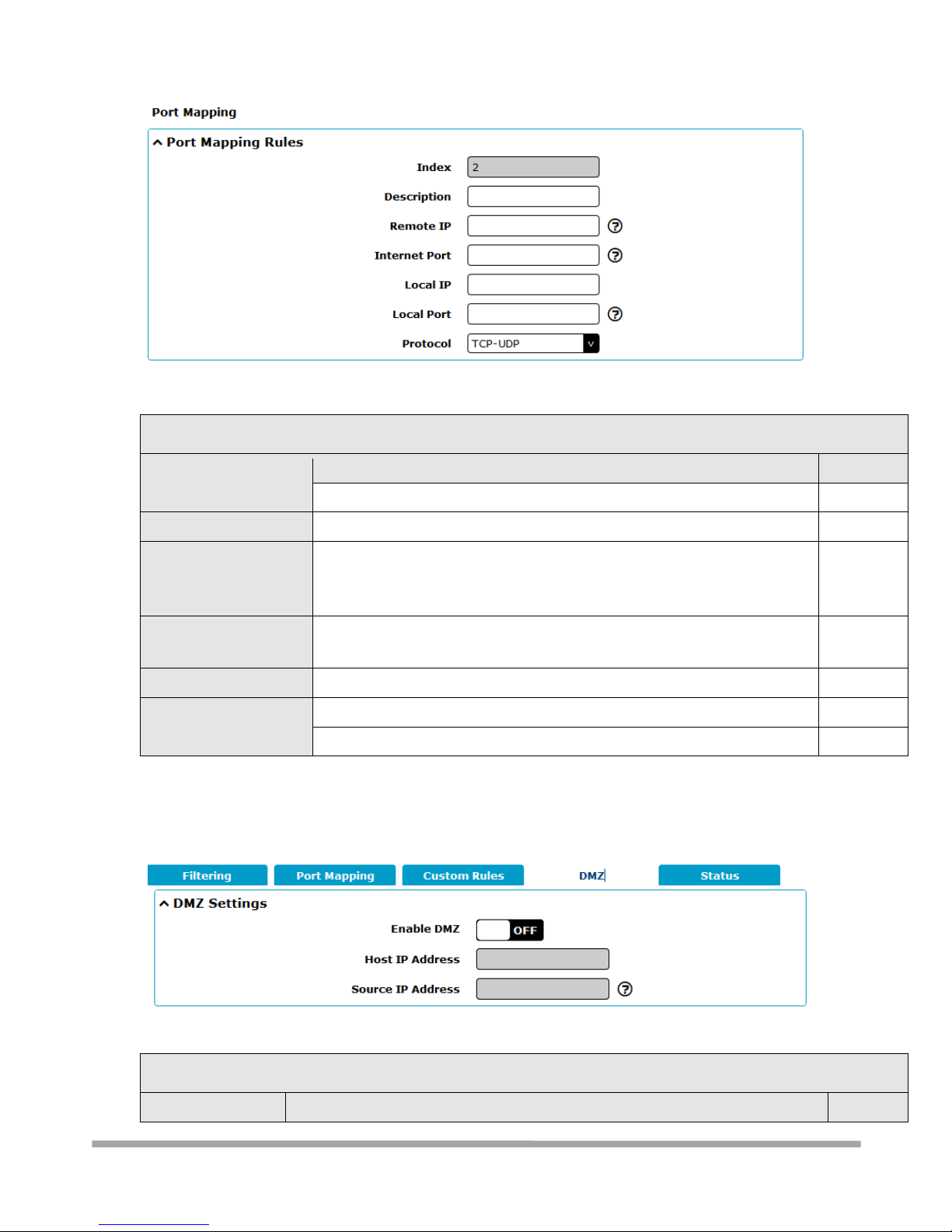
Click + sign below to configure port mapping rules. If you need assistance in
configuration please click on? sign below. Maximum of 40 rules can be added.
Page 65
Multimax_user manual_v.4.0.4 July. 11, 2018 65/139
Confidential
Port Mapping Rules
Item
Description
Default
Index
Indicate the ordinal of the list.
--
Description
Enter a description for this port mapping.
Null
Remote IP
Specify the host or network which can access to the local IP address.
Empty means unlimited. e.g. 10.10.10.10/255.255.255.255 or
192.168.1.0/24
Null
Internet Port
Set the internet port of router which can be accessed by other hosts from
internet.
Null
Local IP
Enter router’s LAN IP which will forward to the internet port of router.
Null
Local Port
Enter the port of router’s LAN IP.
Null
Protocol
Select from “TCP”, “UDP” or “TCP-UDP” as your application required.
TCP-UDP
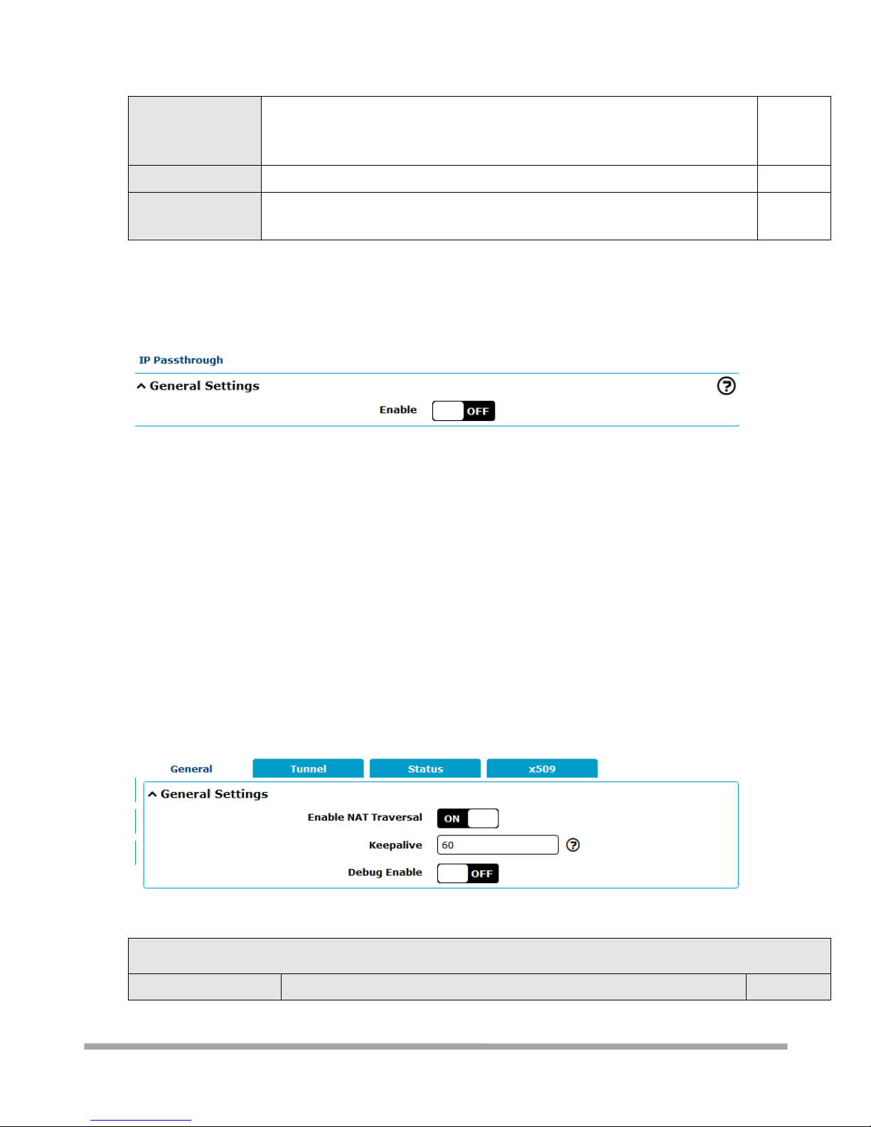
3.7.2.3 - DMZ
A DMZ (De-Militarised Zone) is a section of the local LAN that is allowed access to/from the internet.
In this case, we are doing the equivalent of port mapping the entire WAN IP to a single end-device.
DMZ Settings
Item
Description
Default
Page 66
Multimax_user manual_v.4.0.4 July. 11, 2018 66/139
Confidential
Enable DMZ
Click the toggle button to enable/disable DMZ. DMZ host is a host on the
internal network that has all ports exposed, except those ports otherwise
forwarded.
OFF
Host IP Address
Enter the IP address of the DMZ host on your internal network.
Null
Source IP Address
Set the address which can talk to the DMZ host. 0.0.0.0 means for any
addresses.
Null
3.7.3 - Network > IP Passthrough
Click Network > IP Passthrough > IP Passthrough to enable or disable the IP Pass-through option.
If router enables the IP Pass-through, the terminal device (such as PC) will enable the DHCP Client
mode and connect to LAN port of the router; and after the router dial up successfully, the PC will
automatically obtain the IP address and DNS server address which assigned by ISP.
3.8 – VPN
3.8.1 VPN > IPsec
This section allows you to set the IPsec and the related parameters. Internet Protocol Security
(IPsec) is a protocol suite for secure Internet Protocol (IP) communications that works by
authenticating and encrypting each IP packet of a communication session.
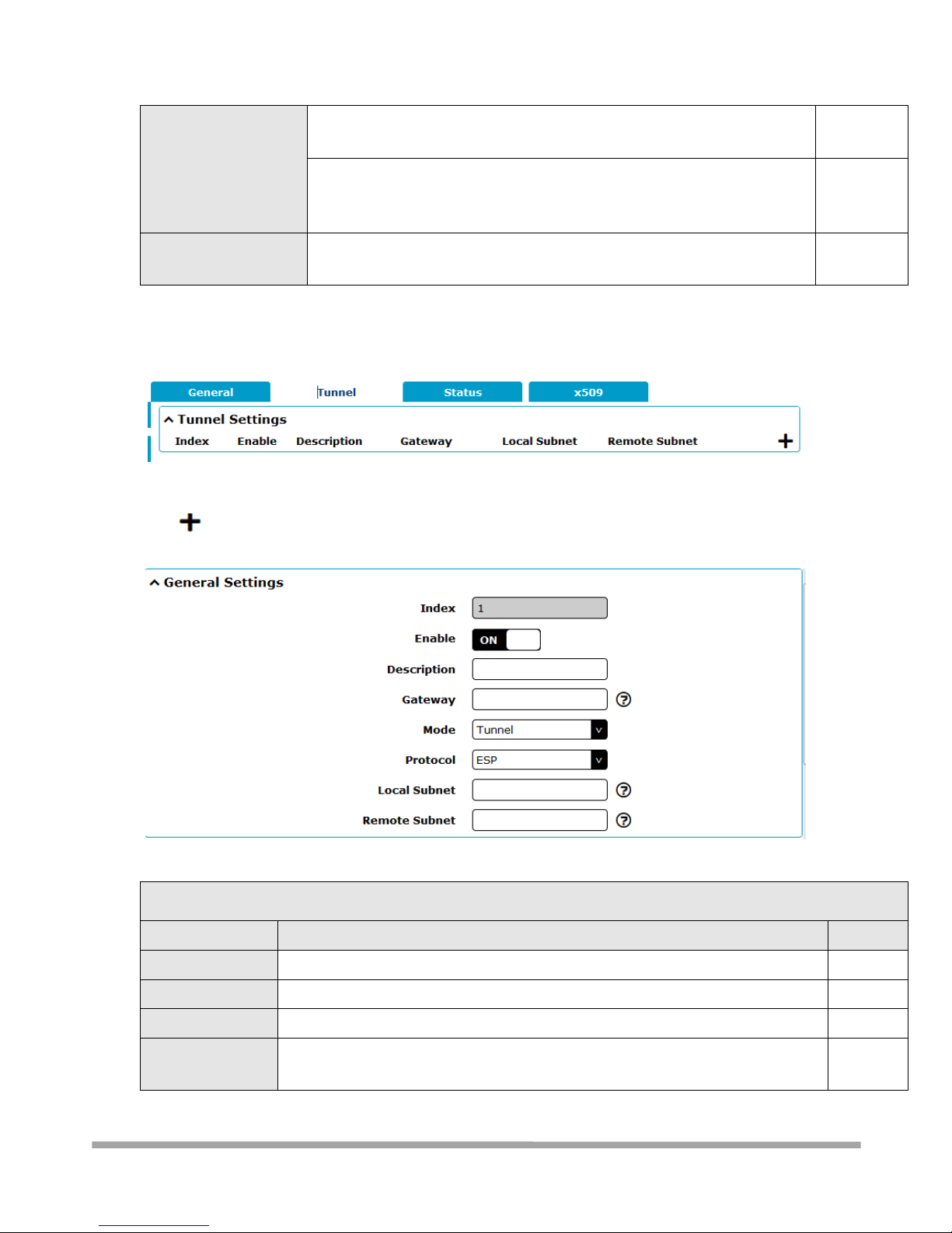
3.8.1.1 - General
General Settings @ General
Item
Description
Default
Page 67
Multimax_user manual_v.4.0.4 July. 11, 2018 67/139
Confidential
Enable NAT Traversal
Click the toggle button to enable/disable the NAT Traversal function. This
option must be enabled when router under NAT environment.
ON
Keepalive
Set the keepalive time, measured in seconds. The router will send packets
to NAT server every keepalive time to avoid record remove from the NAT
list.
60
Debug Enable
Click the toggle button to enable/disable this option. Enable for IPsec VPN
information output to the debug port.
OFF
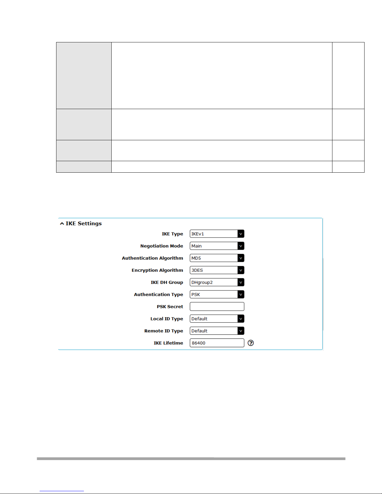
3.8.1.2 - Tunnel
Click to add tunnel settings. Maximum of 3 tunnels can be added.
General Settings @ Tunnel
Item
Description
Default
Index
Indicate the ordinal of the list.
--
Enable
Click the toggle button to enable/disable this IPsec tunnel.
ON
Description
Enter a description for this IPsec tunnel.
Null
Gateway
Enter the address of remote side IPsec VPN server. 0.0.0.0 represents for any
address.
Null
Page 68
Multimax_user manual_v.4.0.4 July. 11, 2018 68/139
Confidential
Mode
Select from “Tunnel” and “Transport”.
Tunnel: Commonly used between gateways, or at an end-station to a
gateway, the gateway acting as a proxy for the hosts behind it
Transport: Used between end-stations or between an end-station and a
gateway, if the gateway is being treated as a host-for example, an encrypted
Telnet session from a workstation to a router, in which the router is the
actual destination
Tunnel
Protocol
Select the security protocols from “ESP” and “AH”.
ESP: Use the ESP protocol
AH: Use the AH protocol
ESP
Local Subnet
Enter the local subnet’s address in CIDR , e.g. 192.168.1.0/24
Null
Remote Subnet
Enter the remote subnet’s address in CIDR, e.g. 10.8.0.0/24
Null
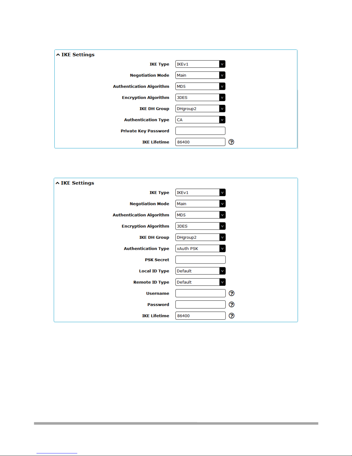
The window is displayed as below when choosing “PSK” as the authentication type.
Page 69
Multimax_user manual_v.4.0.4 July. 11, 2018 69/139
Confidential
The window is displayed as below when choosing “CA” as the authentication type.
The window is displayed as below when choosing “xAuth PSK” as the authentication type.
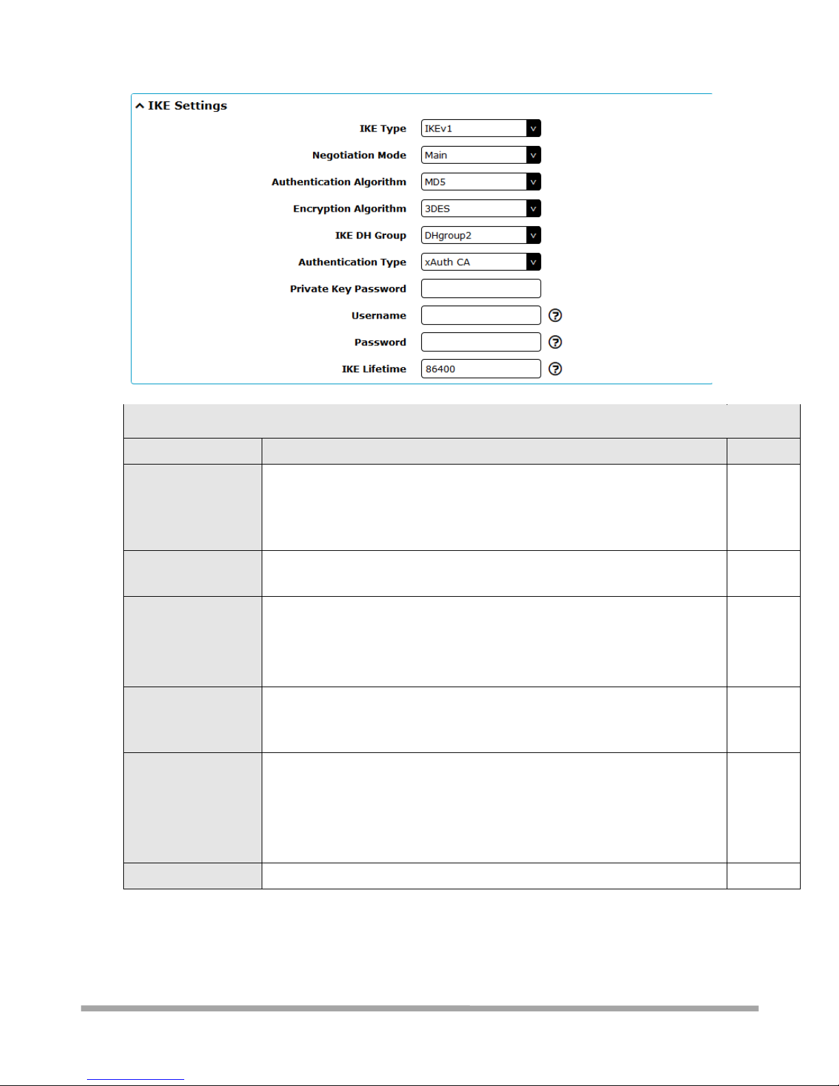
The window is displayed as below when choosing “xAuth CA” as the authentication type.
Page 70
Multimax_user manual_v.4.0.4 July. 11, 2018 70/139
Confidential
IKE Settings
Item
Description
Default
Negotiation Mode
Select from “Main” and “Aggressive” for the IKE negotiation mode in phase 1.
If the IP address of one end of an IPsec tunnel is obtained dynamically, the IKE
negotiation mode must be aggressive. In this case, SAs can be established as
long as the username and password are correct.
Main
Authentication
Algorithm
Select from “MD5”, “SHA1”, “SHA2 256” or “SHA2 512” to be used in IKE
negotiation.
MD5
Encrypt Algorithm
Select from “3DES”, “AES128” and “AES256”to be used in IKE negotiation.
3DES: Use 168-bit 3DES encryption algorithm in CBC mode
AES128: Use 128-bit AES encryption algorithm in CBC mode
AES256: Use 256-bit AES encryption algorithm in CBC mode
3DES
IKE DH Group
Select from “DHgroup2”, “DHgroup5”, “DHgroup14”, “DHgroup15”,
“DHgroup16”, “DHgroup17” or “DHgroup18” to be used in key negotiation
phase 1.
DHgroup2
Authentication Type
Select from “PSK”, “CA”, “xAuth PSK” and “xAuth CA” to be used in IKE
negotiation.
PSK: Pre-shared Key
CA: Certification Authority
xAuth: Extended Authentication to AAA server
PSK
PSK Secret
Enter the pre-shared key.
Null
Page 71
Multimax_user manual_v.4.0.4 July. 11, 2018 71/139
Confidential
Local ID Type
Select from “Default”, “FQDN” and “User FQDN” for IKE negotiation.
Default: Uses an IP address as the ID in IKE negotiation
FQDN: Uses an FQDN type as the ID in IKE negotiation. If this option is
selected, type a name without any at sign (@) for the local security
gateway, e.g., test.robustel.com.
User FQDN: Uses a user FQDN type as the ID in IKE negotiation. If this
option is selected, type a name string with a sign “@” for the local
security gateway, e.g., [email protected].
Default
IKE Settings
Item
Description
Default
Remote ID Type
Select from “Default”, “FQDN” and “User FQDN” for IKE negotiation.
Default: Uses an IP address as the ID in IKE negotiation
FQDN: Uses an FQDN type as the ID in IKE negotiation. If this option is
selected, type a name without any at sign (@) for the local security
gateway, e.g., test.robustel.com.
User FQDN: Uses a user FQDN type as the ID in IKE negotiation. If this
option is selected, type a name string with a sign “@” for the local
security gateway, e.g., [email protected].
Default
Private Key Password
Enter the private key under the “CA” and “xAuth CA” authentication types.
Null
Username
Enter the username used for the “xAuth PSK” and “xAuth CA” authentication
types.
Null
Password
Enter the password used for the “xAuth PSK” and “xAuth CA” authentication
types.
Null
IKE Lifetime
Set the lifetime in IKE negotiation. Before an SA expires, IKE negotiates a new
SA. As soon as the new SA is set up, it takes effect immediately and the old
one will be cleared automatically when it expires.
86400
If click VPN > IPsec > Tunnel > General Settings, and choose ESP as protocol. The specific parameter
configuration is shown as below.
If choose AH as protocol, the window of SA Settings is displayed as below.
Page 72
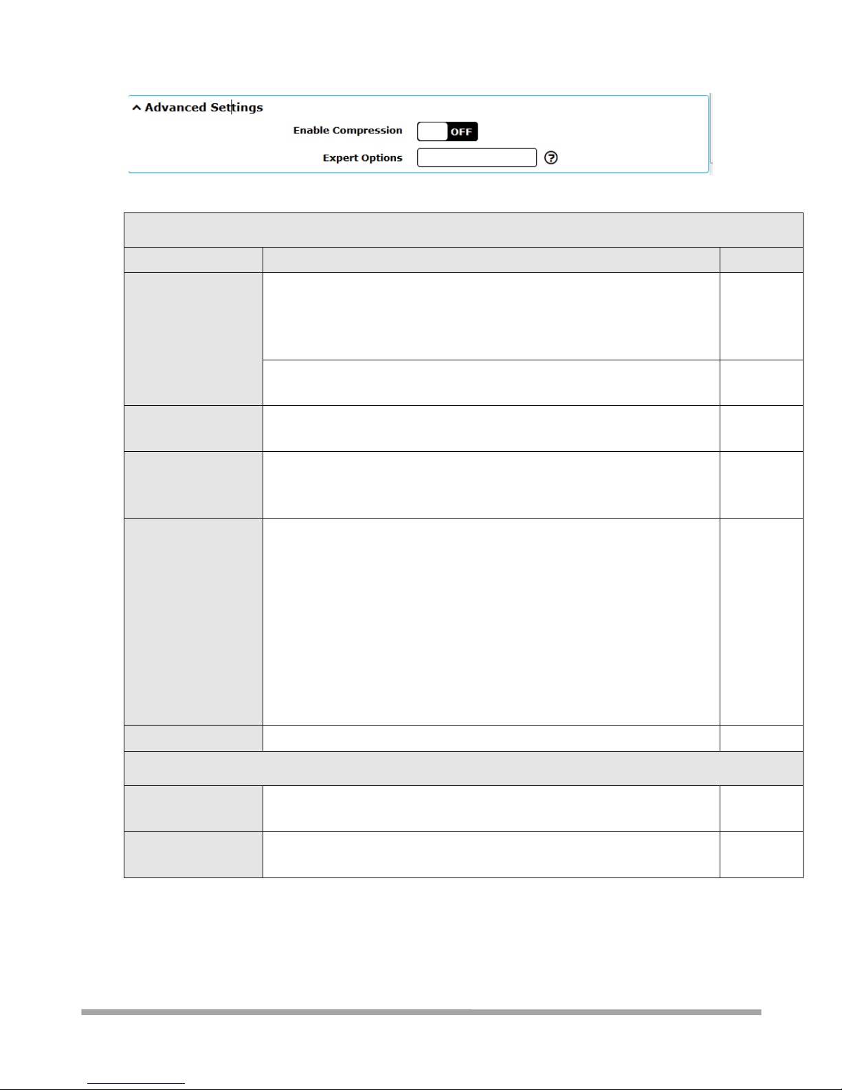
Multimax_user manual_v.4.0.4 July. 11, 2018 72/139
Confidential
SA Settings
Item
Description
Default
Encrypt Algorithm
Select from “3DES”, “AES128” or “AES256” when you select “ESP” in
“Protocol”. Higher security means more complex implementation and lower
speed. DES is enough to meet general requirements. Use 3DES when high
confidentiality and security are required.
3DES
Authentication
Algorithm
Select from “MD5”, “SHA1”, “SHA2 256” or “SHA2 512” to be used in SA
negotiation.
MD5
PFS Group
Select from “DHgroup2”, “DHgroup5”, “DHgroup14”, “DHgroup15”,
“DHgroup16”, “DHgroup17” or “DHgroup18” to be used in SA negotiation.
DHgroup2
SA Lifetime
Set the IPsec SA lifetime. When negotiating to set up IPsec SAs, IKE uses the
smaller one between the lifetime set locally and the lifetime proposed by
the peer.
28800
DPD Interval
Set the interval after which DPD is triggered if no IPsec protected packets is
received from the peer. DPD is a Dead peer detection. DPD irregularly
detects dead IKE peers. When the local end sends an IPsec packet, DPD
checks the time the last IPsec packet was received from the peer. If the time
exceeds the DPD interval, it sends a DPD hello to the peer. If the local end
receives no DPD acknowledgment within the DPD packet retransmission
interval, it retransmits the DPD hello. If the local end still receives no DPD
acknowledgment after having made the maximum number of
retransmission attempts, it considers the peer already dead, and clears the
IKE SA and the IPsec SAs based on the IKE SA.
60
DPD Failures
Set the timeout of DPD (Dead Peer Detection) packets.
180
Advanced Settings
Enable Compression
Click the toggle button to enable/disable this option. Enable to compress the
inner headers of IP packets.
OFF
Expert Options
Add more PPP configuration options here, format: config-desc;config-desc,
e.g. protostack=netkey;plutodebug=none
Null
3.8.1.3 - Status
This section allows you to view the status of the IPsec tunnel.
Page 73
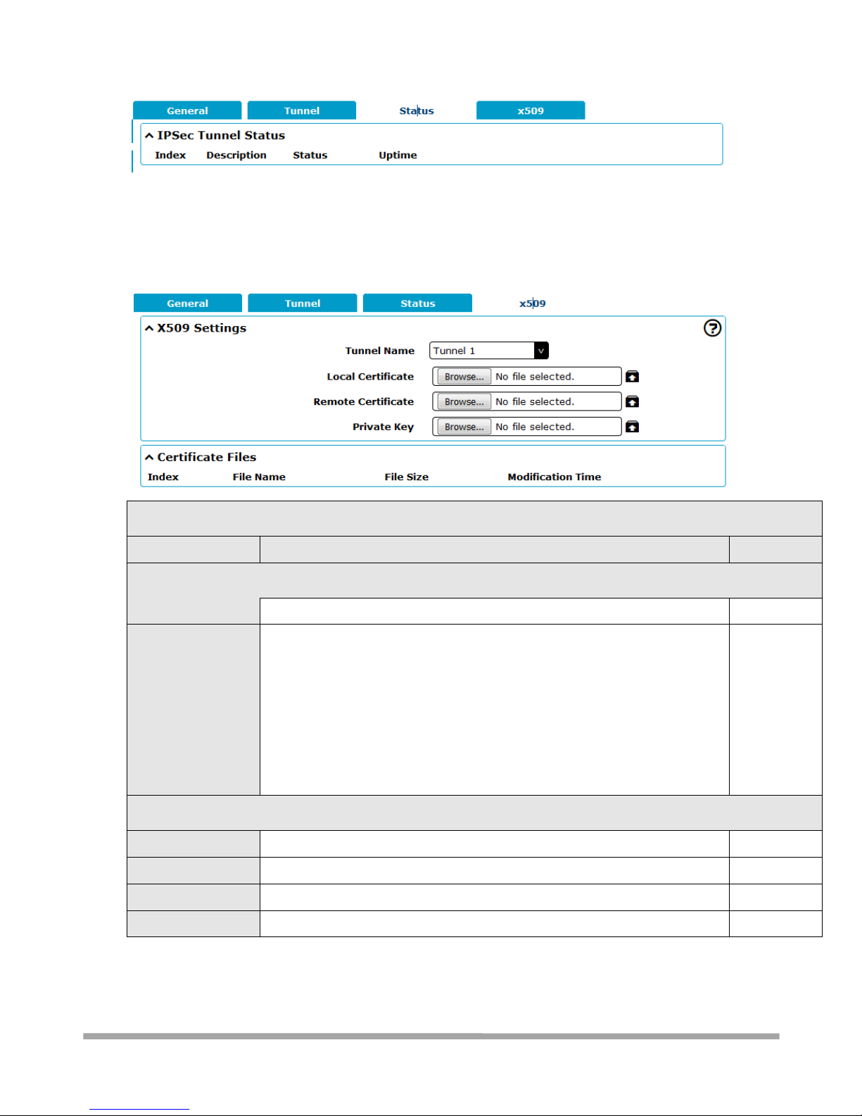
Multimax_user manual_v.4.0.4 July. 11, 2018 73/139
Confidential
3.8.1.4 - x509
User can upload the X509 certificates for the IPsec tunnel in this section.
x509
Item
Description
Default
X509 Settings
Tunnel Name
Choose a valid tunnel.
Tunnel 1
Certificate Files
Click on “Choose File” to locate the certificate file from your computer, and
then import this file into your router.
The correct file format is displayed as follows:
@ca.crt – Certificate Authority file (your certificate signers signature)
@remote.crt – the certificate used by the remote end
@local.crt - the certificate used by this end
@private.key – the private key for the local certificate
@crl.pem – certificate revocation list
Null
Certificate Files
Index
Indicate the ordinal of the list.
--
Filename
Show the imported certificate’s name.
Null
File Size
Show the size of the certificate file.
Null
Last Modification
Show the timestamp of that the last time to modify the certificate file.
Null
Page 74
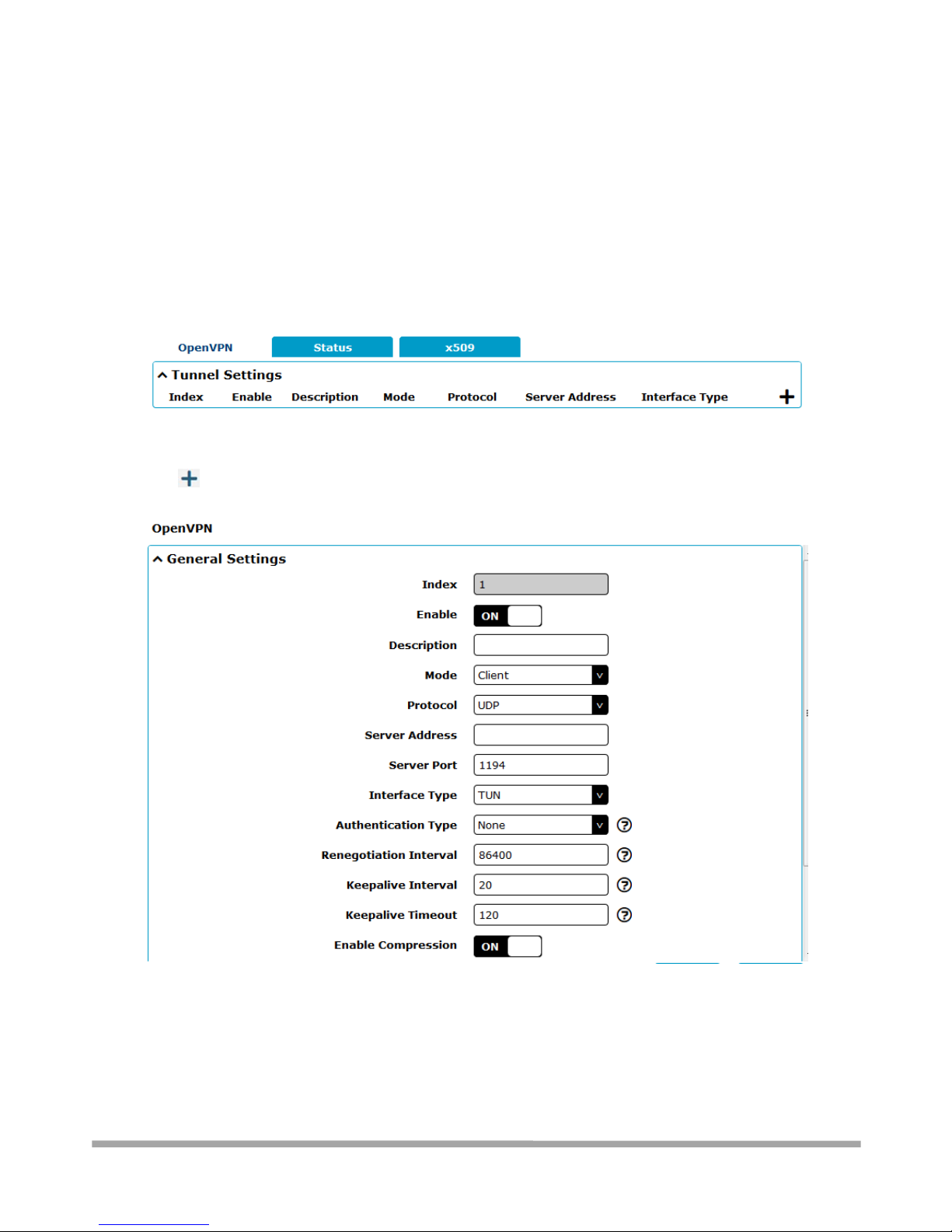
Multimax_user manual_v.4.0.4 July. 11, 2018 74/139
Confidential
3.8.2 VPN > OpenVPN
This section allows you to set the OpenVPN and the related parameters. OpenVPN is an opensource software application that implements virtual private network (VPN) techniques for creating
secure point-to-point or site-to-site connections in routed or bridged configurations and remote
access facilities. Router supports point-to-point and point-to-points connections.
3.8.2.1 - OpenVPN
Click to add tunnel settings. The maximum count is 3. The window is displayed as below when
choosing “None” as the authentication type. By default, the mode is “Client”.
The window is displayed as below when choosing “P2P” as the mode.
Page 75
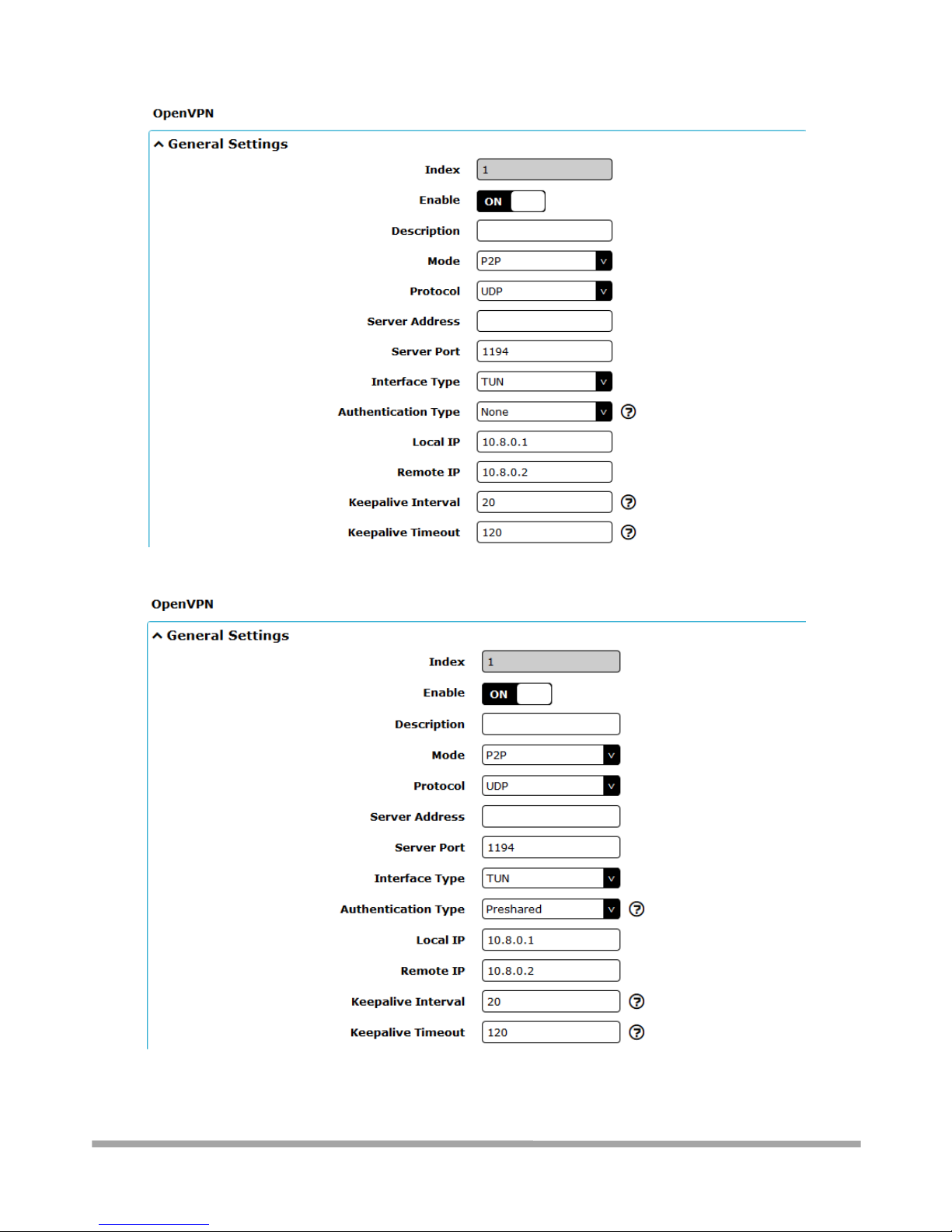
Multimax_user manual_v.4.0.4 July. 11, 2018 75/139
Confidential
The window is displayed as below when choosing “Preshared” as the authentication type.
The window is displayed as below when choosing “Password” as the authentication type.
Page 76
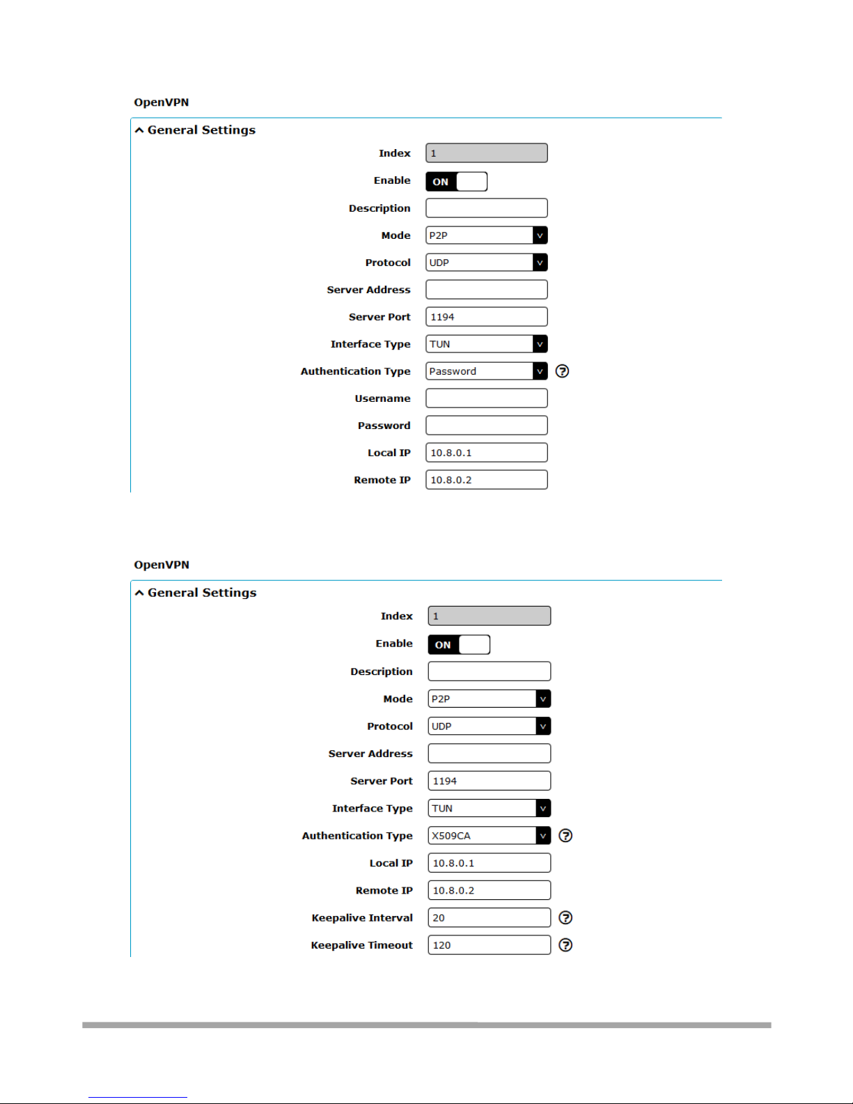
Multimax_user manual_v.4.0.4 July. 11, 2018 76/139
Confidential
The window is displayed as below when choosing “X509CA” as the authentication type.
Page 77
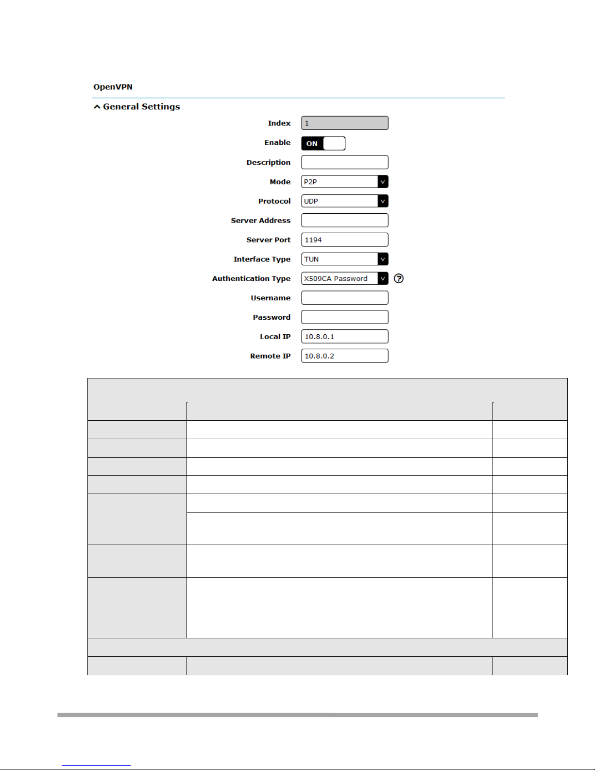
Multimax_user manual_v.4.0.4 July. 11, 2018 77/139
Confidential
The window is displayed as below when choosing “X509CA Password” as the authentication type.
General Settings @ OpenVPN
Item
Description
Default
Index
Indicate the ordinal of the list.
--
Enable
Click the toggle button to enable/disable this OpenVPN tunnel.
ON
Description
Enter a description for this OpenVPN tunnel.
Null
Mode
Select from “P2P” for site-to-site or “Client” for client-to-site.
Client
Protocol
Select from “UDP”, “TCP-Client” or “TCP-Server”.
UDP
Server Address
Enter the end-to-end IP address or the domain of the remote OpenVPN
server.
Null
Server Port
Enter the end-to-end listener port or the listener port of the OpenVPN
server.
1194
Interface Type
Select from “TUN”, “TAP” which are two different kinds of device
interface for OpenVPN. The difference between TUN and TAP device is
that a TUN device is a point-to-point virtual device on network while a
TAP device is a virtual device on Ethernet.
TUN
General Settings @ OpenVPN
Item
Description
Default
Page 78

Multimax_user manual_v.4.0.4 July. 11, 2018 78/139
Confidential
Authentication Type
Select from “None”, “Preshared”, “Password”, “X509CA” and “X509CA
Password”.
Note: “None” and “Preshared” authentication type are only working
with P2P mode.
None
Username
Enter the username used for “Password” or “X509CA Password”
authentication type.
Null
Password
Enter the password used for “Password” or “X509CA Password”
authentication type.
Null
Local IP
Enter the local virtual IP (IP assigned to tunnel at this end).
10.8.0.1
Remote IP
Enter the remote virtual IP (IP assigned to tunnel at other end).
10.8.0.2
Encrypt Algorithm
Select from “BF”, “DES”, “DES-EDE3”, “AES128”, “AES192” and
“AES256”.
BF: Use 128-bit BF encryption algorithm in CBC mode
DES: Use 64-bit DES encryption algorithm in CBC mode
DES-EDE3: Use 192-bit 3DES encryption algorithm in CBC mode
AES128: Use 128-bit AES encryption algorithm in CBC mode
AES192: Use 192-bit AES encryption algorithm in CBC mode
AES256: Use 256-bit AES encryption algorithm in CBC mode
BF
Renegotiation
Interval
Set the renegotiation interval. If connection failed, OpenVPN will
renegotiate when the renegotiation interval reached.
86400
Keepalive Interval
Set keepalive (ping) interval to check if the tunnel is active.
20
Keepalive Timeout
Set the keepalive timeout. Trigger OpenVPN restart after n seconds pass
without reception of a ping or other packet from remote.
120
Private Key Password
Enter the private key password under the “X509CA” and “X509CA
Password” authentication type. This is the password required to access
the contents of the key file.
Null
Enable Compression
Click the toggle button to enable/disable this option. Enable to compress
the data stream of the header.
ON
Enable NAT
Click the toggle button to enable/disable the NAT option. When
enabled, the source IP address of host behind router will be disguised
before accessing the remote OpenVPN client.
OFF
Verbose Level
Select the level of the output log and values from 0 to 11.
0: No output except fatal errors
1~4: Normal usage range
5: Output R and W characters to the console for each packet read
and write
6~11: Debug info range
0
Page 79
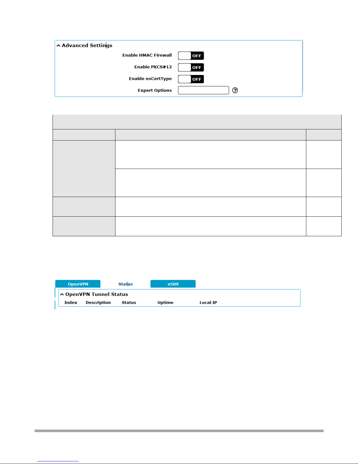
Multimax_user manual_v.4.0.4 July. 11, 2018 79/139
Confidential
Advanced Settings @ OpenVPN
Item
Description
Default
Enable HMAC Firewall
Click the toggle button to enable/disable this option. Add an additional
layer of HMAC authentication on top of the TLS control channel to protect
against DoS attacks.
OFF
Enable PKCS#12
Click the toggle button to enable/disable the PKCS#12 certificate. It is an
exchange of digital certificate encryption standard, used to describe
personal identity information.
OFF
Enable nsCertType
Click the toggle button to enable/disable nsCertType. Require that peer
certificate was signed with an explicit nsCertType designation of "server".
OFF
Expert Options
Enter some other options of OpenVPN in this field. Each expression can be
separated by a ‘;’.
Null
3.8.2.2 - Status
This section allows you to view the status of the OpenVPN tunnel.
3.8.2.3 - x509
User can upload the X509 certificates for the OpenVPN in this section.
Page 80
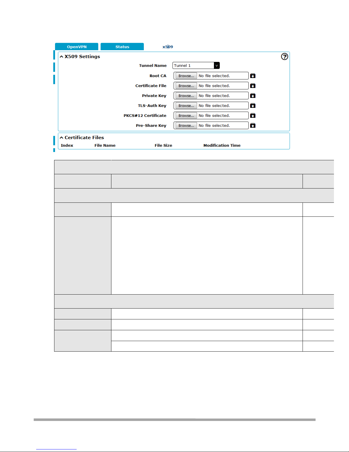
Multimax_user manual_v.4.0.4 July. 11, 2018 80/139
Confidential
x509
Item
Description
Default
X509 Settings
Tunnel Name
Choose a valid tunnel.
Tunnel 1
Certificate Files
Click on “Choose File” to locate the certificate file from your computer, and
then import this file into your router.
The correct file format is displayed as follows:
@ca.crt – Certificate Authority – your certificate signers signature.
@remote.crt – the remote end certificate
@local.crt – the local end certificate
@private.key – the private key of the local certificate
@crl.pem - - certificate revocation list
@client.p12
Null
Certificate Files
Index
Indicate the ordinal of the list.
--
Filename
Show the imported certificate’s name.
Null
File Size
Show the size of the certificate file.
Null
Last Modification
Show the timestamp of that the last time to modify the certificate file.
Null
3.8.3 VPN > GRE
This section allows you to set the GRE and the related parameters. Generic Routing Encapsulation
(GRE) is a tunnelling protocol that can encapsulate a wide variety of network layer protocols inside
virtual point-to-point links over an Internet Protocol network.
Page 81
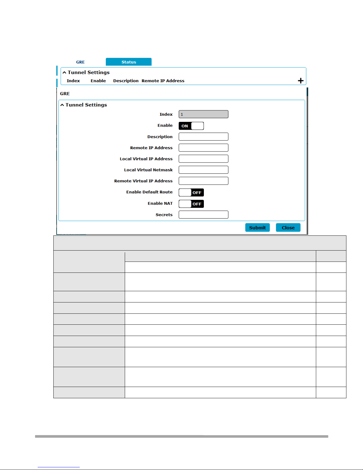
Multimax_user manual_v.4.0.4 July. 11, 2018 81/139
Confidential
3.8.3.1 - GRE
Tunnel Settings @ GRE
Item
Description
Default
Index
Indicate the ordinal of the list.
--
Enable
Click the toggle button to enable/disable this GRE tunnel. Maximum of 3
tunnel is allowed
ON
Description
Enter a description for this GRE tunnel.
Null
Remote IP Address
Set the remote real IP address of the GRE tunnel.
Null
Local Virtual IP Address
Set the local virtual IP address of the GRE tunnel (tunnel IP).
Null
Local Virtual Netmask
Set the local virtual Netmask of the GRE tunnel.
Null
Remote Virtual IP Address
Set the remote virtual IP Address of the GRE tunnel (tunnel IP).
Null
Enable Default Route
Click the toggle button to enable/disable this option. When enabled, all
the traffics of the router will go through the GRE VPN.
OFF
Enable NAT
Click the toggle button to enable/disable this option. This option must be
enabled when router under NAT environment.
Disable
Secrets
Set the key of the GRE tunnel.
Null
Page 82
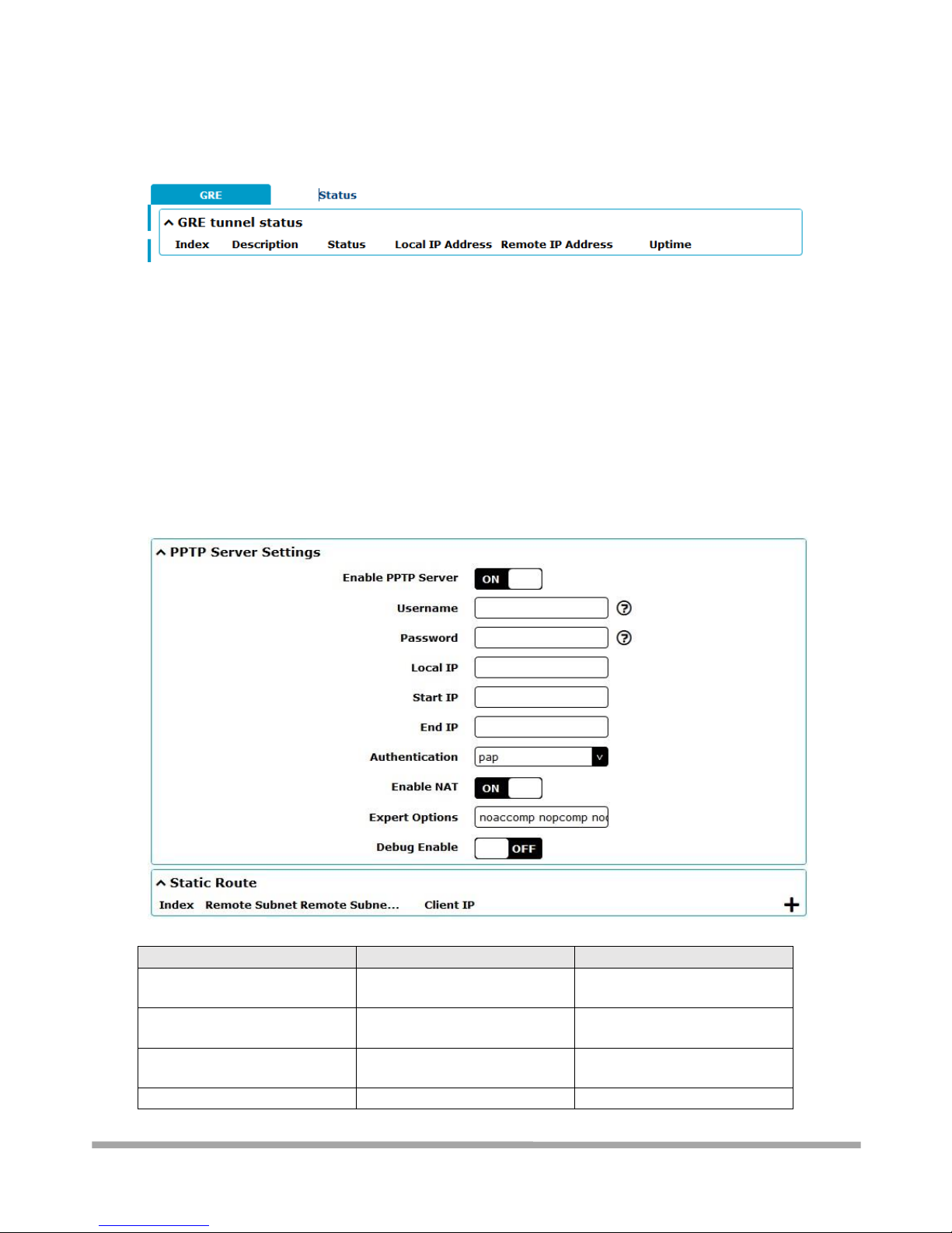
Multimax_user manual_v.4.0.4 July. 11, 2018 82/139
Confidential
3.8.3.2 - Status
This section allows you to view the status of GRE tunnel.
3.8.4 VPN > PPTP
PPTP (“Point to Point Tunnelling Protocol”) is a VPN technology developed my Microsoft.
Due to the popularity of the Windows platform, and seamless integration by Microsoft of PPTP into
Windows, it is an extremely popular choice when it needs to work “out of the box”. You should be
aware that the encryption used by this tunnel type is known to be vulnerable to attack, and use is
deprecated.
Multimax can be both a PPTP client and/or a PPTP server.
3.8.4.1 VPN > PPTP > Server
Item
Description
Setting
Enable PPTP Server
Click the toggle button to
enable PPTP VPN server.
ON
Username
Enter the username which will
be used by L2TP client.
Enter accordingly
Password
Enter the password provided
by your PPTP server.
Enter accordingly
Local IP
Enter the IP address of the
Enter accordingly
Page 83
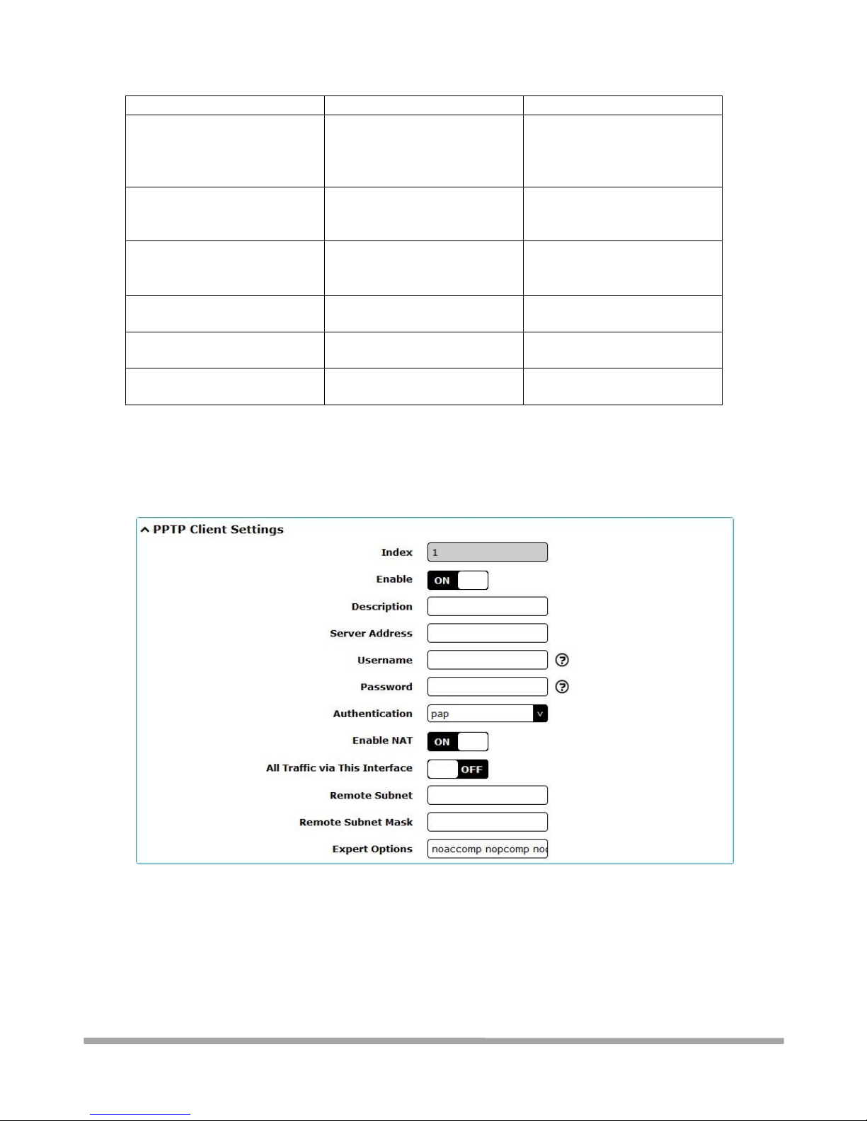
Multimax_user manual_v.4.0.4 July. 11, 2018 83/139
Confidential
PPTP server.
Start IP
Enter the start IP address
which will assign to the PPTP
clients
Enter accordingly
End IP
Enter The end IP Address
which will assign to the PPTP
clients
Enter accordingly
Authentication
Select
from”pap”,”chap”,”mschap
v1” and ”mschap v2”.
Enter accordingly
Enable NAT
Click the toggle button to
enable NAT option for PPTP.
ON
Expert Options
Enter expert options of PPTP
VPN in this field.
None
Debug Enable
Click the toggle button to
enable debugging for PPTP.
OFF
Static route settings:
3.8.4.2 VPN > PPTP > Client
Page 84

Multimax_user manual_v.4.0.4 July. 11, 2018 84/139
Confidential
Item
Description
Setting
Enable PPTP Server
Click the toggle button to
enable PPTP VPN server.
ON
Username
Enter the username which will
be used by L2TP client.
Enter accordingly
Password
Enter the password provided
by your PPTP server.
Enter accordingly
Authentication
Select
from”pap”,”chap”,”mschap
v1” and ”mschap v2”.
Enter accordingly
Enable NAT
Click the toggle button to
enable NAT option for PPTP.
ON
All traffic via This Interface
Turn on to use tunnel as
default gateway
OFF
Remote subnet
The subnet used by the
remote end of the tunnel
(remote end local LAN)
Enter accordingly
Remote subnet mask
The subnet mask used by the
remote end of the tunnel.
Enter accordingly
Expert Options
Enter expert options of PPTP
VPN in this field.
None
3.8.5 VPN > L2TP
L2TP (“Layer 2 Transport Protocol”) is a form of VPN developed by Cisco Systems that can carry
traffic not seen in most other tunnelling protocols. Because it is Layer 2 based, it can “bridge”
physically separated networks and make them appear as a single network. This protocol can
transport non-IP packets such as ARP and other broadcast-based protocols.
Multimax can be both an L2TP client and/or an L2TP server.
Page 85
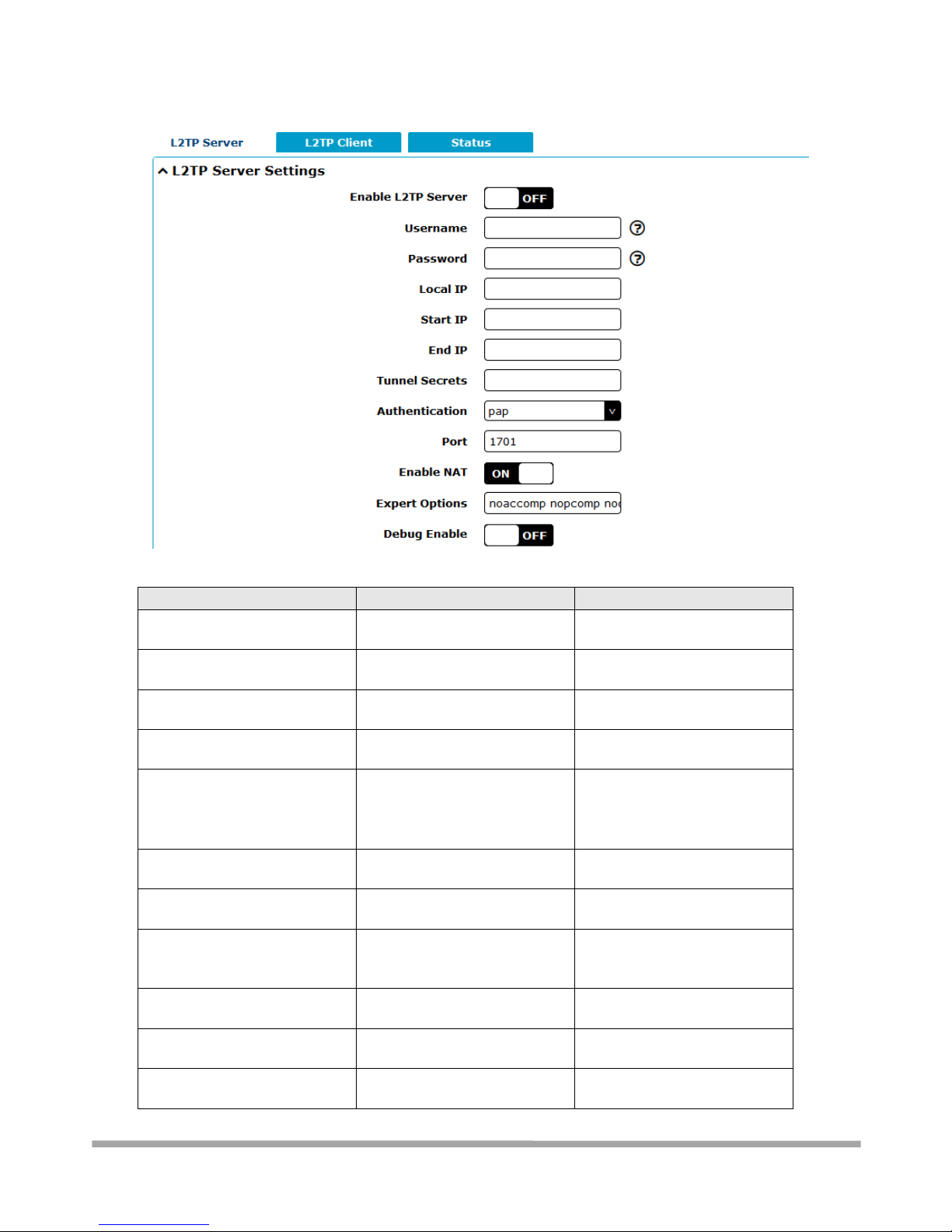
Multimax_user manual_v.4.0.4 July. 11, 2018 85/139
Confidential
3.8.5.1 VPN > L2TP > Server
Item
Description
Setting
EnableL2TP Server
Click the toggle button to
enable L2TP VPN server.
ON
Username
Enter the username which will
be used by L2TP client.
Enter accordingly
Password
Enter the password provided
by your L2TP server.
Enter accordingly
Local IP
Enter the IP address of the
L2TP server.
Enter accordingly
Start IP
Enter the start IP address
which will assign to the L2TP
clients
Enter accordingly
End IP
Enter the end IP address which
will assign to the L2TP clients.
Enter accordingly
Tunnel Secrets
Enter the tunnel secret which
will assign to L2TP client.
None
Authentication
Select
from”pap”,”chap”,”mschap
v1” and ”mschap v2”.
Enter accordingly
Port
Enter the port number of the
L2TP client.
1701
Enable NAT
Click the toggle button to
enable NAT option for L2TP.
ON
Expert Options
Enter expert options of L2TP
VPN in this field.
None
Page 86
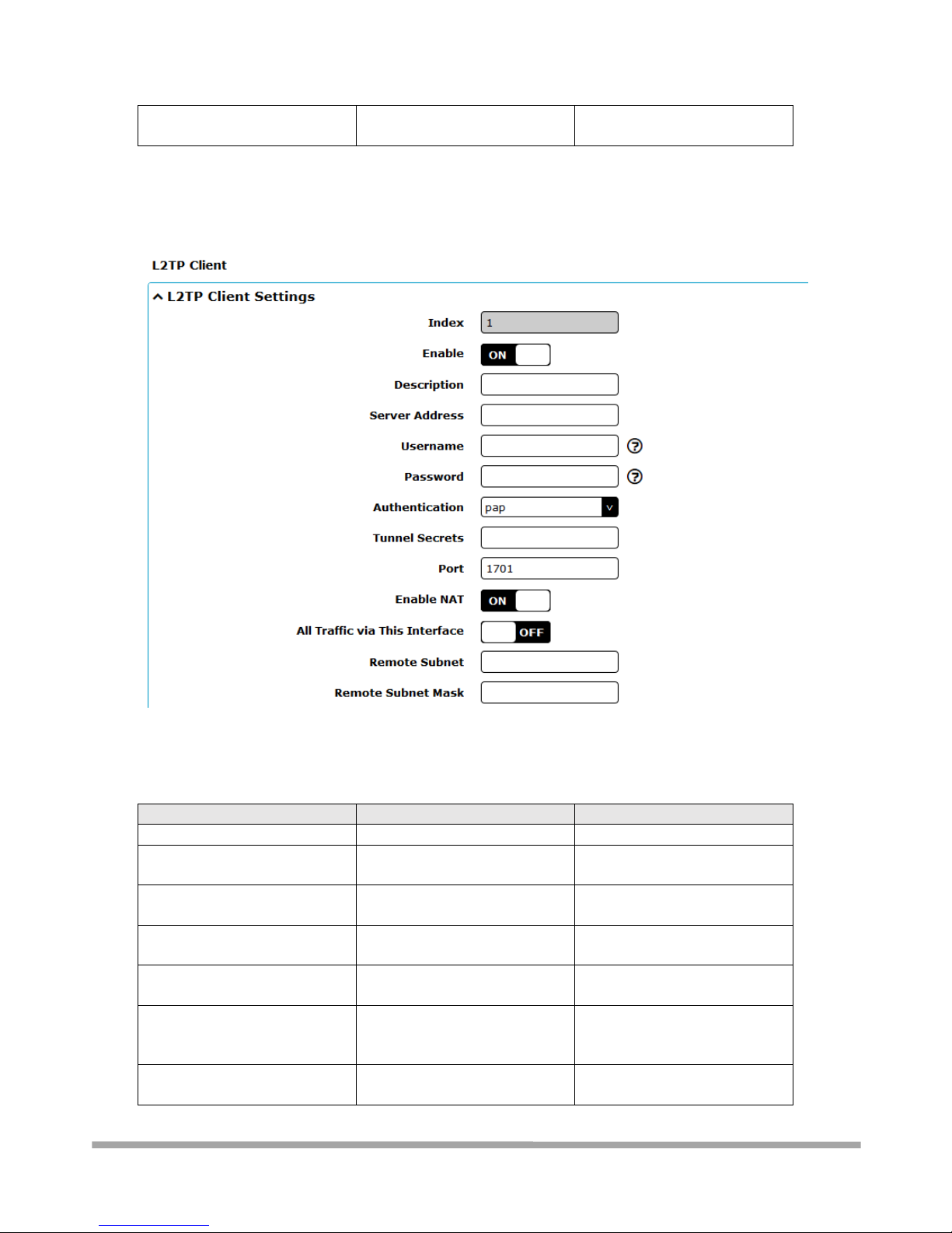
Multimax_user manual_v.4.0.4 July. 11, 2018 86/139
Confidential
Debug Enable
Click the toggle button to
enable debugging for L2TP.
OFF
3.8.5.2 VPN > L2TP >Client
Item
Description
Setting
Index
Show the ordinal of the list.
--
Enable
Click the toggle button to
enable this L2TP VPN tunnel.
ON
Description
Enter a description for this
L2TP VPN tunnel.
Null
Server Address
Enter the server address of the
L2TP VPN.
Enter accordingly
Username
Enter the username provided
by your L2TP VPN.
Enter accordingly
Password
Enter the password provided
by your
L2TP server.
Enter accordingly
Authentication
Select from “pap”, “chap”,
“mschap v1” and “mschap v2”.
Enter accordingly
Page 87
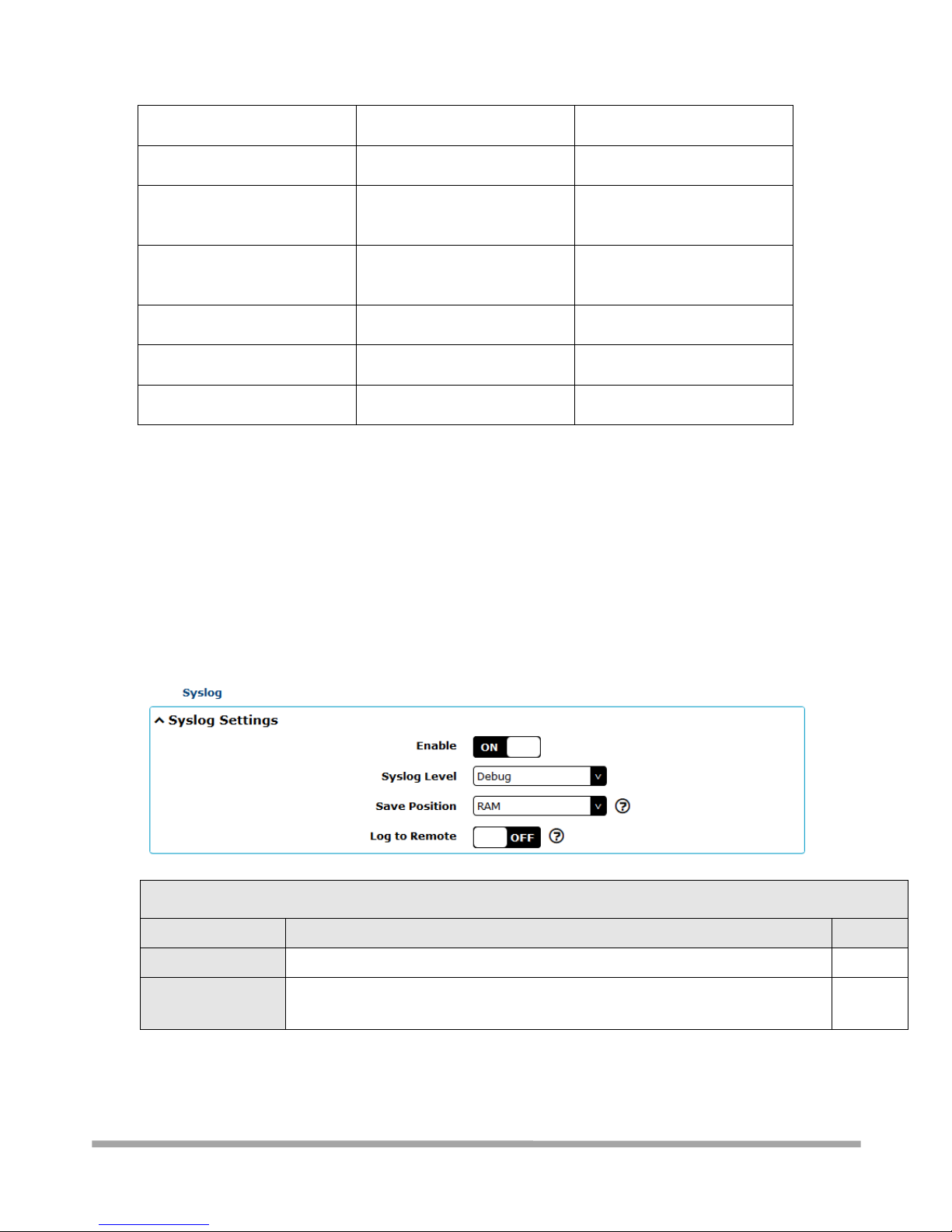
Multimax_user manual_v.4.0.4 July. 11, 2018 87/139
Confidential
Tunnel Secrets
Enter the tunnel secret
provided by L2TP server.
None
Port
Enter the port number of the
L2TP client.
1701
Enable NAT
Click the toggle button to
enable the NAT feature of
L2TP.
Enable
All Traffic via This Interface
After click to enable this
feature, all data traffic will be
sent via L2TP tunnel.
Disable
Remote Subnet
Enter the subnet address of
your L2TP server.
Enter accordingly
Remote Subnet Mask
Enter the subnet mask of your
L2TP server.
Enter accordingly
Expert Options
Enter the expert options of
L2TP VPN in this field.
None
3.9 – Services
3.9.1 Services > Syslog
This section allows you to set the syslog parameters. The system log of the router can be saved in
the local, also supports to be sent to remote log server and specified application debugging. By
default, the “Log to Remote” option is disabled.
The window is displayed as below when enabling the “Log to Remote” option.
Syslog Settings
Item
Description
Default
Enable
Click the toggle button to enable/disable the Syslog settings option.
OFF
Syslog Level
Select from “Debug”, “Info”, “Notice”, “Warning” or “Error”, which from low to
high. The lower level will output more syslog in detail.
Debug
Page 88
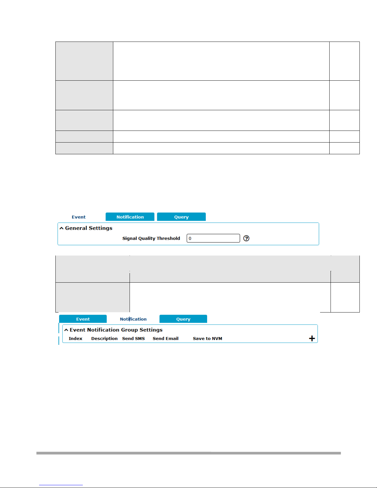
Multimax_user manual_v.4.0.4 July. 11, 2018 88/139
Confidential
Save Position
Select the save position from “RAM”, “NVM” or “Console”. Choose “RAM”, the
data will be cleared after reboot.
Note: It's not recommended that saving syslog to NVM (Non-Volatile Memory)
for a long time.
RAM
Log to Remote
Click the toggle button to enable/disable this option. Enable to allow router
sending syslog to the remote syslog server. You need to enter the IP and Port of
the syslog server.
OFF
Add Identifier
Click the toggle button to enable/disable this option. When enabled, you can add
serial number to syslog message which used for loading Syslog to RobustLink.
OFF
Remote IP Address
Enter the IP address of syslog server when enabling the “Log to Remote” option.
Null
Remote Port
Enter the port of syslog server when enabling the “Log to Remote” option.
514
3.9.2 Services > Event
This section allows you to set the event parameters. Event feature provides an ability to send alerts
by SMS or Email when certain system events occur.
General Settings @ Event
Item
Description
Default
Signal Quality Threshold
Set the threshold for signal quality. Router will generate a log event when
the actual threshold is less than the specified threshold. 0 means disable
this option.
0
Page 89
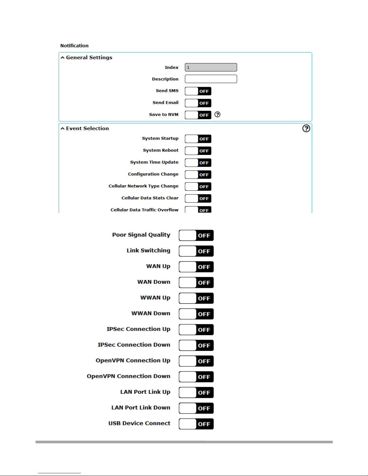
Multimax_user manual_v.4.0.4 July. 11, 2018 89/139
Confidential
Page 90
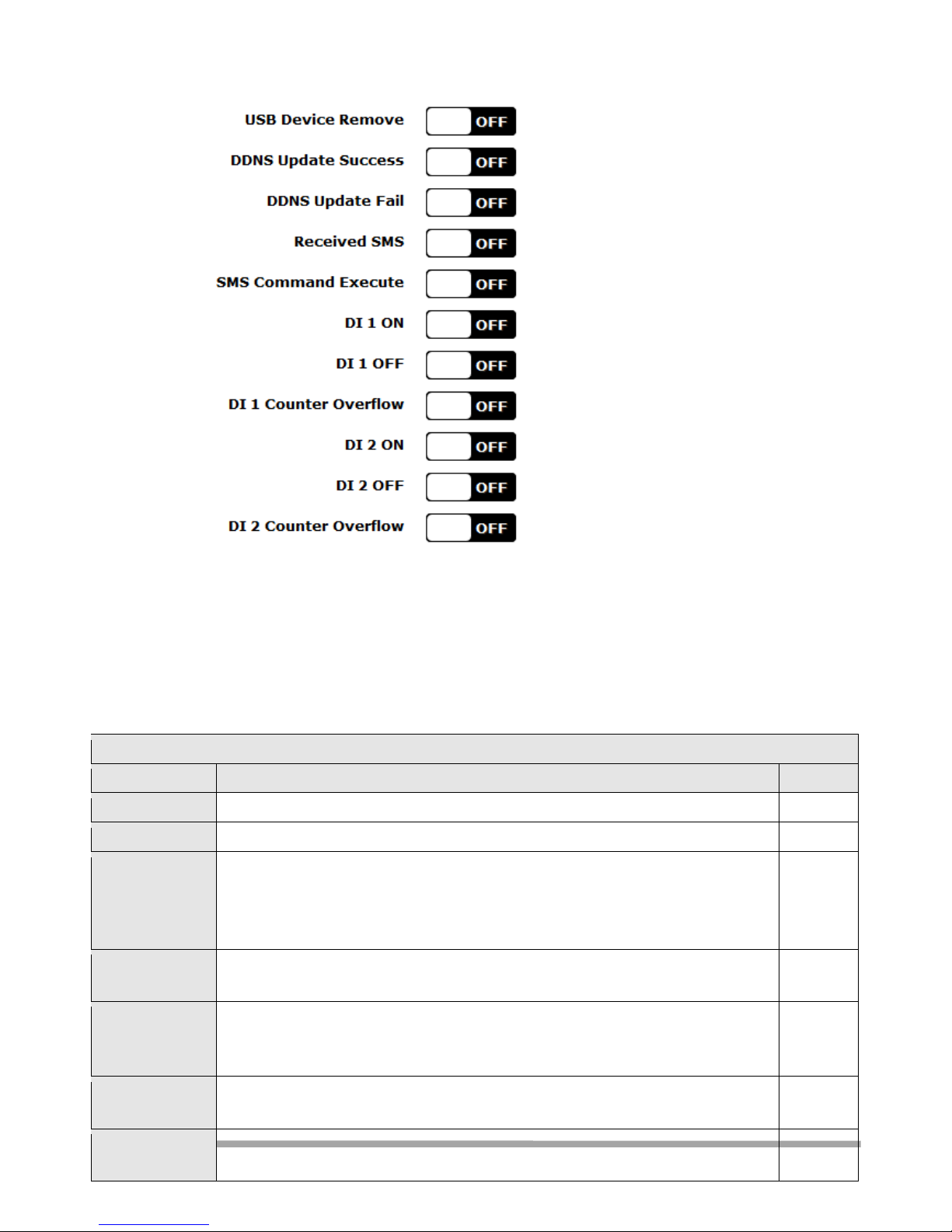
Multimax_user manual_v.4.0.4 July. 11, 2018 90/139
Confidential
General Settings @ Notification
Item
Description
Default
Index
Indicate the ordinal of the list.
--
Description
Enter a description for this group.
Null
Sent SMS
Click the toggle button to enable/disable this option. When enabled, the router will
send notification to the specified phone numbers via SMS if event occurs. Set the
related phone number in “3.24 Services > Email”, and use ‘;’to separate each
number.
OFF
Phone Number
Enter the phone numbers used for receiving event notification. Use a semicolon (;)
to separate each number.
Null
Send Email
Click the toggle button to enable/disable this option. When enabled, the router will
send notification to the specified email box via Email if event occurs. Set the related
email address in “3.24 Services > Email”.
OFF
Email Address
Enter the email addresses used for receiving event notification. Use a space to
separate each address.
Null
Save to NVM
Click the toggle button to enable/disable this option. Enable to save event to nonvolatile memory.
OFF
Page 91
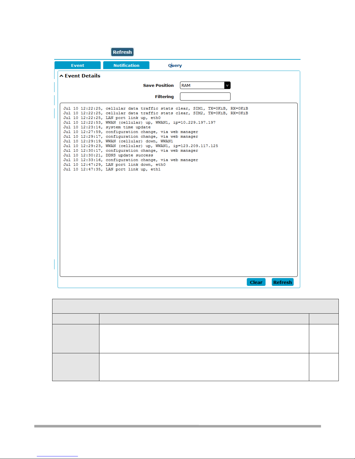
Multimax_user manual_v.4.0.4 July. 11, 2018 91/139
Confidential
The following window you can query various types of events record. Press clear to clear all the data
and Click to query
Event Details
Item
Description
Default
Save Position
Select the events’ save position from “RAM” or “NVM”.
RAM: Random-access memory
NVM: Non-Volatile Memory
RAM
Filter Message
Event will be filtered according to the Filter Message that the user set. Click the
“Refresh” button, the filtered event will be displayed in the follow box. Use “&” to
separate more than one filter message, such as message1&message2.
Null
Page 92
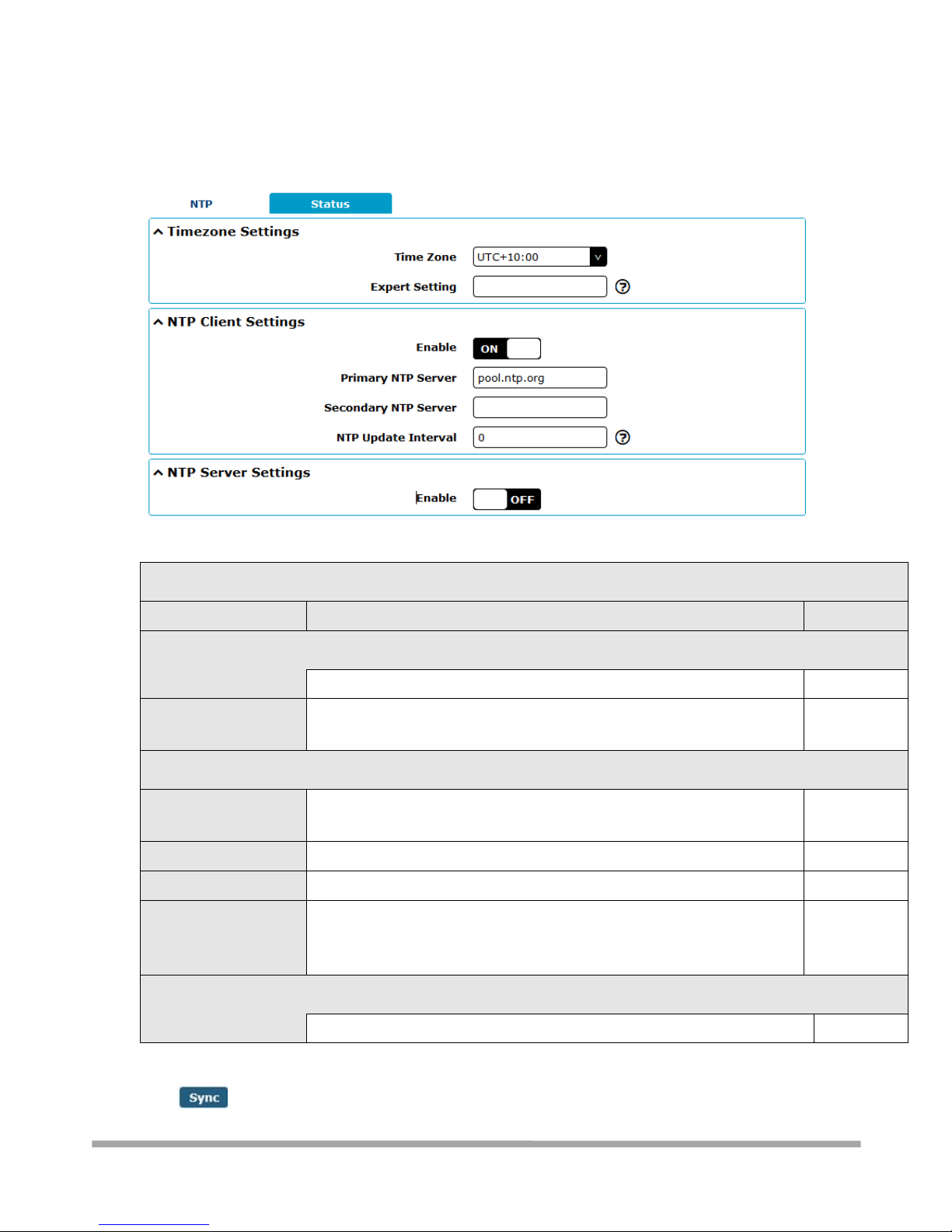
Multimax_user manual_v.4.0.4 July. 11, 2018 92/139
Confidential
3.9.3 Services > NTP
This section allows you to set the related NTP (Network Time Protocol) parameters, including Time
zone, NTP Client and NTP Server.
NTP
Item
Description
Default
Timezone Settings
Time Zone
Click the drop down list to select the time zone you are in.
UTC +08:00
Expert Setting
Specify the time zone with Daylight Saving Time in TZ environment
variable format. The Time Zone option will be ignored in this case.
Null
NTP Client Settings
Enable
Click the toggle button to enable/disable this option. Enable to
synchronize time with the NTP server.
ON
Primary NTP Server
Enter primary NTP Server’s IP address or domain name.
pool.ntp.org
Secondary NTP Server
Enter secondary NTP Server’s IP address or domain name.
Null
NTP Update interval
Enter the interval (minutes) which NTP client synchronize the time from
NTP server. Minutes wait for next update, and 0 means update only
once.
0
NTP Server Settings
Enable
Click the toggle button to enable the NTP server option.
OFF
This window allows you to view the current time of router and also synchronize the router time.
Click button to synchronize the router time with PC’s.
Page 93
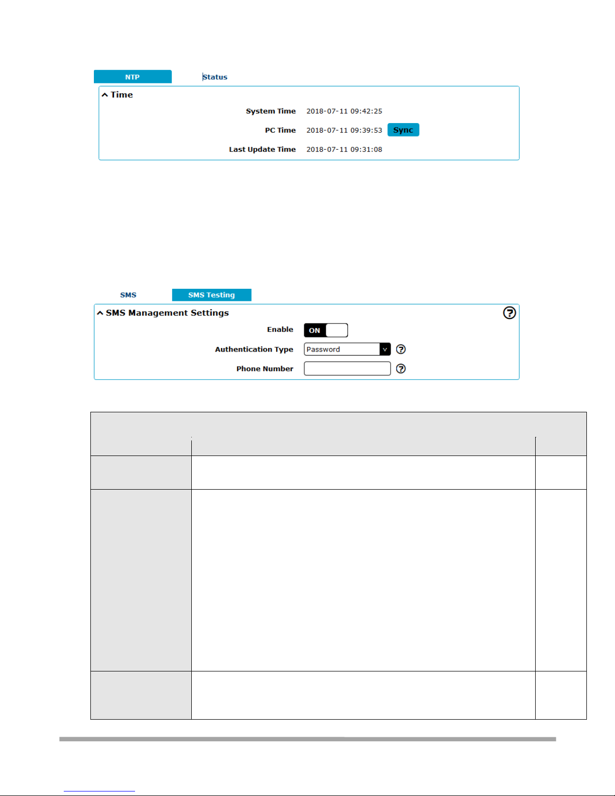
Multimax_user manual_v.4.0.4 July. 11, 2018 93/139
Confidential
3.9.4 - Services > SMS
This section allows you to set SMS parameters. Router supports SMS management, and user can
control and configure their routers by sending SMS. For more details about SMS control, refer to
4.2.2 SMS Remote Control.
SMS Management Settings
Item
Description
Default
Enable
Click the toggle button to enable/disable the SMS Management option. Note:
If this option is disabled, the SMS configuration is invalid.
ON
Authentication Type
Select Authentication Type from “Password”, “Phonenum” or “Both”.
Password: Use the same username and password as WEB manager for
authentication. For example, the format of the SMS should be “username:
password; cmd1; cmd2; …”
Note: Set the WEB manager password in System > User Management
section.
Phonenum: Use the Phone number for authenticating, and user should set
the Phone Number that is allowed for SMS management. The format of
the SMS should be “cmd1; cmd2; …”
Both: Use both the “Password” and “Phonenum” for authentication. User
should set the Phone Number that is allowed for SMS management. The
format of the SMS should be “username: password; cmd1; cmd2; …”
Password
Phone Number
Set the phone number used for SMS management, and use ‘; ‘to separate each
number.
Note: It can be null when choose “Password” as the authentication type.
Null
Page 94
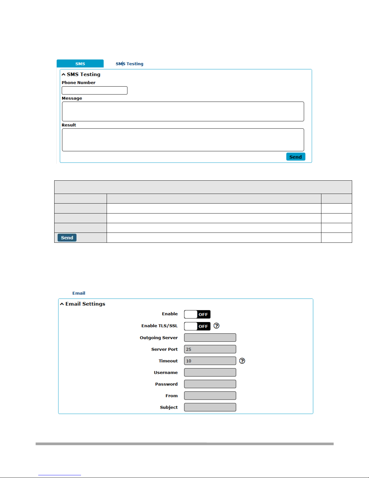
Multimax_user manual_v.4.0.4 July. 11, 2018 94/139
Confidential
User can test the current SMS service whether it is available in this section.
SMS Testing
Item
Description
Default
Phone Number
Enter the specified phone number which can receive the SMS from router.
Null
Message
Enter the message that router will send it to the specified phone number.
Null
Result
The result of the SMS test will be displayed in the result box.
Null
Click the button to send the test message.
--
3.9.5 - Services > Email
Email function supports to send the event notifications to the specified recipient by ways of email.
Page 95
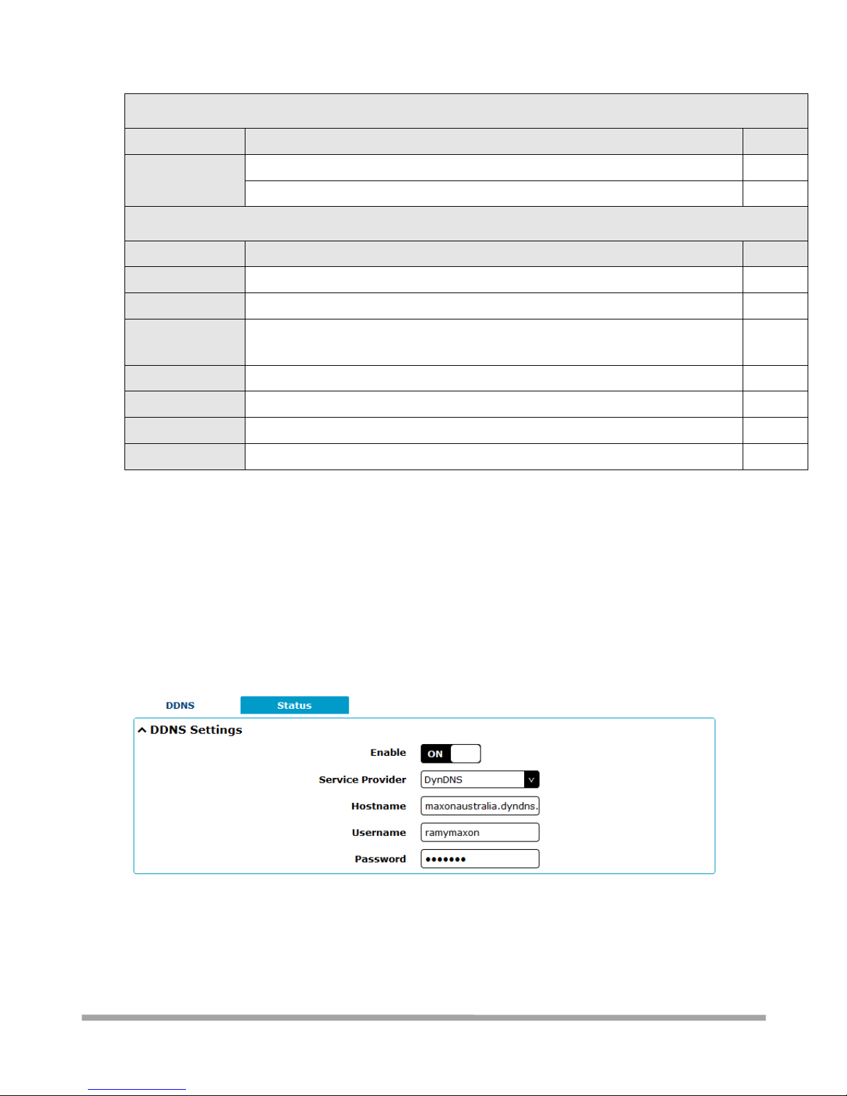
Multimax_user manual_v.4.0.4 July. 11, 2018 95/139
Confidential
Email Settings
Item
Description
Default
Enable
Click the toggle button to enable/disable the Email option.
OFF
Enable TLS/SSL
Click the toggle button to enable/disable the TLS/SSL option.
OFF
Email Settings
Item
Description
Default
Outgoing server
Enter the SMTP server IP Address or domain name.
Null
Server port
Enter the SMTP server port.
25
Timeout
Set the max time for sending email to SMTP server. When the server doesn’t
receive the email over this time, it will try to resend.
10
Username
Enter the username which has been registered from SMTP server.
Null
Password
Enter the password of the username above.
Null
From
Enter the source address of the email.
Null
Subject
Enter the subject of this email.
Null
3.9.6 Services > DDNS
This section allows you to set the DDNS parameters. The Dynamic DNS function allows you to alias a
dynamic IP address to a static domain name, allows you whose ISP does not assign them a static IP
address to use a domain name. This is especially useful for hosting servers via your connection, so
that anyone wishing to connect to you may use your domain name, rather than having to use your
dynamic IP address, which changes from time to time. This dynamic IP address is the WAN IP
address of the router, which is assigned to you by your ISP. The service provider defaults to
“DynDNS”, as shown below.
When “Custom” service provider chosen, the window is displayed as below.
Page 96
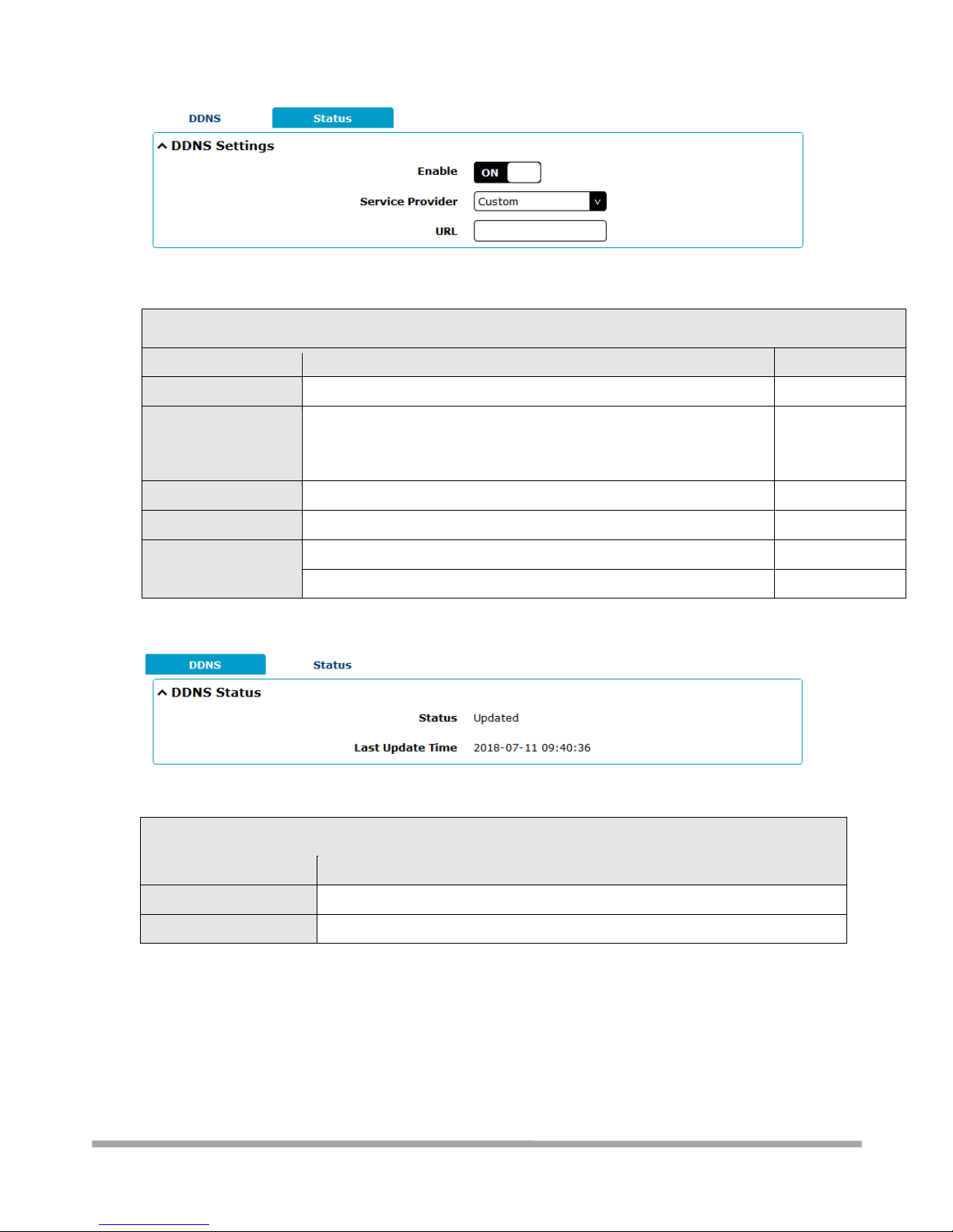
Multimax_user manual_v.4.0.4 July. 11, 2018 96/139
Confidential
DDNS Settings
Item
Description
Default
Enable
Click the toggle button to enable/disable the DDNS option.
OFF
Service Provider
Select the DDNS service from “DynDNS”, “NO-IP” or “3322”. Note:
the DDNS service only can be used after registered by
Corresponding service provider.
DynDNS
Hostname
Enter the hostname provided by the DDNS server.
Null
Username
Enter the username provided by the DDNS server.
Null
Password
Enter the password provided by the DDNS server.
Null
URL
Enter the URL customized by user.
Null
Click “Status” bar to view the status of the DDNS.
DDNS Status
Item
Description
Status
Display the current status of the DDNS.
Last Update Time
Display the date and time for the DDNS was last updated successfully.
3.9.7 Services > SSH
Router supports SSH password access and secret-key access.
Page 97
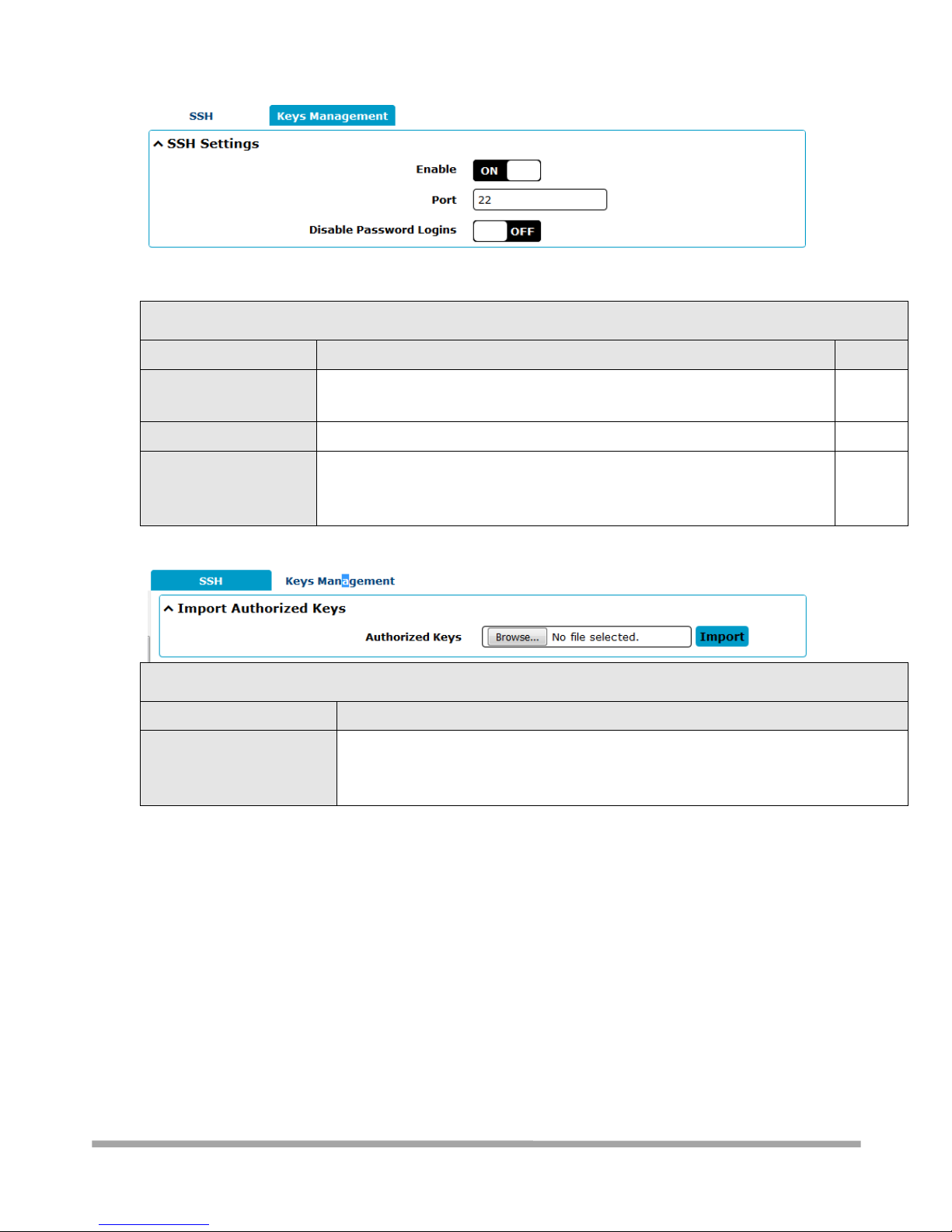
Multimax_user manual_v.4.0.4 July. 11, 2018 97/139
Confidential
SSH Settings
Item
Description
Default
Enable
Click the toggle button to enable/disable this option. When enabled, you can
access the router via SSH.
OFF
Port
Set the port of the SSH access.
22
Disable Password Logins
Click the toggle button to enable/disable this option. When enabled, you
cannot use username and password to access the router via SSH. In this case,
only the key can be used for login.
OFF
Keys Management
Item
Description
Authorized Keys
Click on “Choose File” to locate an authorized key from your computer, and then
click “Import” to import this key into your router.
Note: This option is valid when enabling the password logins option.
Page 98
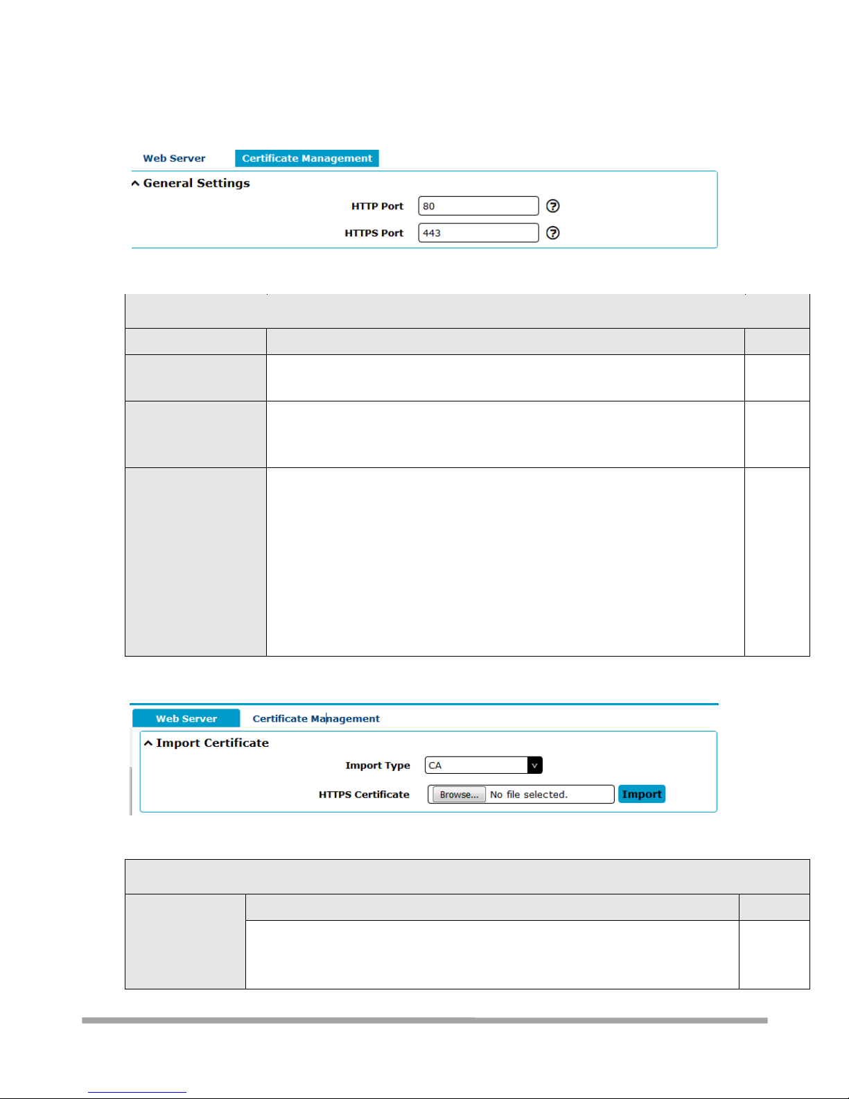
Multimax_user manual_v.4.0.4 July. 11, 2018 98/139
Confidential
3.9.8 Services > Web Server
This section allows you to modify the parameters of Web Server.
Basic @ Web Server
Item
Description
Default
HTTP Port
Enter the HTTP port number you want to change in router’s Web Server. On a
Web server, port 80 is the port that the server "listens to" or expects to receive
80
from a Web client. If you configure the router with other HTTP Port number
except 80, only adding that port number then you can login router’s Web
Server.
HTTPS Port
Enter the HTTPS port number you want to change in router’s Web Server. On a
Web server, port 443 is the port that the server "listens to" or expects to
receive from a Web client. If you configure the router with other HTTPS Port
number except 443, only adding that port number then you can login router’s
Web Server.
Note: HTTPS is more secure than HTTP. In many cases, clients may be
exchanging confidential information with a server, which needs to be secured in
order to prevent unauthorized access.
443
This section allows you to import the certificate file into the route.
Certificate Management
Item
Description
Default
Import Type
Select from “CA” and “Private Key”.
CA: a digital certificate issued by CA center
Private Key: a private key file
CA
Page 99
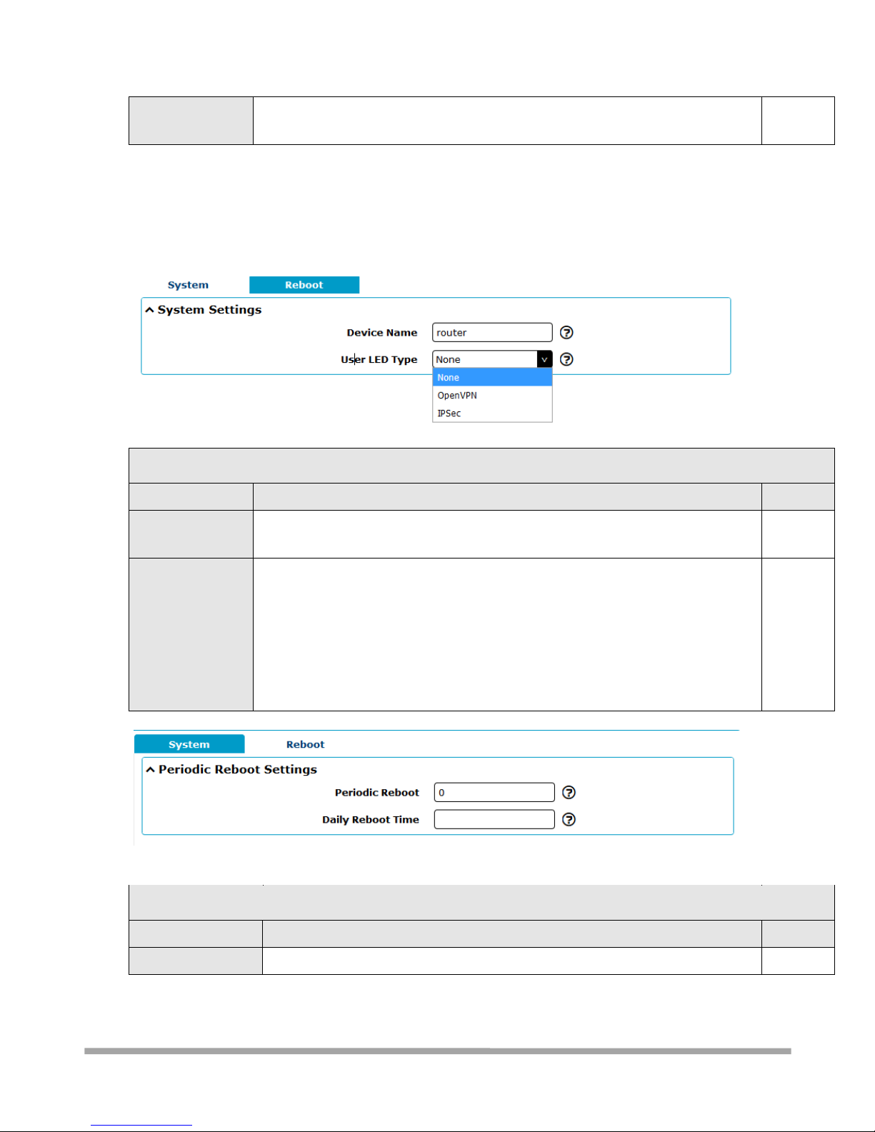
Multimax_user manual_v.4.0.4 July. 11, 2018 99/139
Confidential
HTTPS Certificate
Click on “Choose File” to locate the certificate file from your computer, and then
click “Import” to import this file into your router.
--
3.9.10 Services > Advanced
This section allows you to set the Advanced and parameters.
System Settings
Item
Description
Default
Device Name
Set the device name to distinguish different devices you have installed; valid
characters are a-z, A-Z, 0-9, @, ., -, #, $, and *.
router
User LED Type
Specify the display type of your USR LED. Select from “None”, “OpenVPN”, “IPsec”
or None: Meaningless indication, and the LED is off
OpenVPN: USR indicator showing the OpenVPN status
IPsec: USR indicator showing the IPsec status
Note: For more details about USR indicator, see “2.2 LED Indicators”.
None
Reboot
Item
Description
Default
Periodic Reboot
Set the reboot period of the router. 0 means disable.
0
Page 100

Multimax_user manual_v.4.0.4 July. 11, 2018 100/139
Confidential
Daily Reboot Time
Set the daily reboot time of the router, you should follow the format as HH: MM,
in 24h time frame, otherwise the data will be invalid. Leave it empty means
disable.
Null
3.9.11 System > Debug
This section allows you to check and download the syslog details.
 Loading...