

Page 1

M-16-11
REV. A
FEBRUARY 2017
• Warnings
• Decal & Plate Locations
• Standard Control Locations
• Liftgate & Retention Ramp Operation
Operation Manual Contains:
© MAXON Lift Corp. 2017
To fi nd maintenance information for your
BMR Liftgate, go to www.maxonlift.com.
Click the PRODUCTS, COLUMNLIFT & BMR
buttons. Open the Maintenance Manual in
the PRODUCT DOCUMENTATION window.
For parts, click on the PARTS PORTAL,
COLUMNLIFT & BMR buttons.
Page 2

Page 3

TABLE OF CONTENTS
SUMMARY OF CHANGES: M-16-11, REVISION A ................5
WARNINGS ..............................................................................6
DECALS & PLATES .................................................................8
STANDARD CONTROL LOCATIONS ......................................10
POWER DOWN CONTROLS (IF EQUIPPED) ........................11
PUMP BOX CONTROLS ..........................................................12
FORKLIFT ADVISORY ............................................................13
LOADING VEHICLE ................................................................14
OPENING THE PLA TFORM ....................................................14
LOWERING THE PLA TFORM .................................................14
OPENING THE RETENTION RAMP ........................................15
POSITIONING LOAD ...............................................................16
RAISING & UNLOADING PLATFORM .....................................17
UNLOADING VEHICLE ...........................................................19
OPENING THE PLA TFORM ....................................................19
LOWERING THE PLA TFORM .................................................19
OPENING RAMP TO RETENTION POSITION ........................20
RAISING THE PLA TFORM ......................................................21
POSITIONING LOAD ...............................................................22
LOWERING & UNLOADING PLATFORM ................................23
STOWING PLATFORM ............................................................24
STOW RETENTION RAMP ......................................................24
Page 4

USING CART STOPS (IF EQUIPPED) ....................................26
USING AUTO CART STOPS (IF EQUIPPED) .........................29
DOCK LOADING & UNLOADING ...........................................32
LOWER PLATFORM BELOW DOCK LEVEL...........................32
Page 5

5
PAGE DESCRIPTION OF CHANGE
COVER Updated REV. and date of release.
8 Updated decal positions on RH column.
SUMMARY OF CHANGES: M-16-11, REVISION A
Page 6

6
WARNINGS
2. Do not exceed rated load capacity of the Liftgates which is
3500 lbs. for model BMR-3500, 4400 lbs. for model BMR44, 5500 lbs. for model BMR-55, and 6600 lbs. for model
BMR-66.
3. Do not allow any part of your body to be placed under, within, or
around any portion of the moving Liftgate or its mechanisms, or in
a position that would trap them between the platform and the fl oor
of truck body (or between platform and the ground) when Liftgate
is operated.
4. Consider the safety and location of bystanders and
location of nearby objects when operating the Liftgate. Stand
to one side of platform while operating the Liftgate. Be certain
that the area the Liftgate will move through during operation
is clear of all obstacles.
5. Comply with all attached instruction decals and warning decals.
11. Above all, USE GOOD COMMON SENSE when operating this
Liftgate.
8. Do not move vehicle unless Liftgate is correctly stowed.
6. Keep decals clean and legible. If decals are illegible or missing,
have them replaced. Get free replacement decals from Maxon.
7. Never drive a forklift on the Liftgate platform.
10. A correctly installed Liftgate will operate smoothly and reasonably
quiet. The only noticeable noise, during Liftgate operation, is from
the power unit while the platform is being opened (SD models
only), lowered (power down models only), raised, or closed. Listen
for scraping, grating and binding noises and have the problem
corrected before continuing to operate the Liftgate.
MAXON Lift Corp. Customer Service
11921 Slauson Ave
Santa Fe Springs, CA 90670
(800) 227-4116
WARNING
!
9. Correctly stow platform when not in use. Extended platforms
could create a hazard for people and vehicles passing by.
1. Incorrect operation of this Liftgate can result in serious personal
injury. Comply with WARNINGS and Liftgate operating instructions
in this manual. Do not allow untrained persons or children to oper-
ate the Liftgate. If you need to replace an Operation Manual, additional copies are available from:
12. Never use a cell phone while operating the Liftgate.
Page 7

7
THIS PAGE INTENTIONALLY LEFT BLANK
Page 8
8
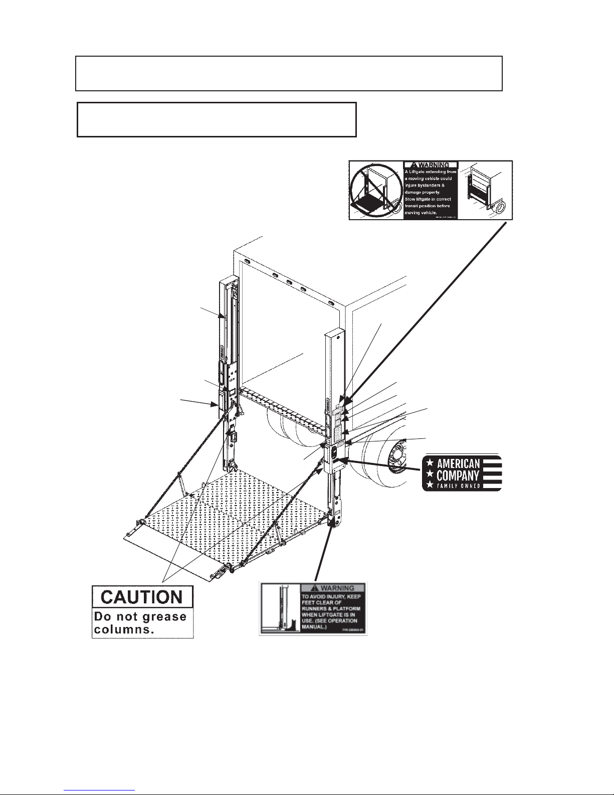
DECALS & PLATES
FIG. 8-1
NOTE: Ensure there is no residue, dirt, or corrosion where decals are attached.
If necessary, clean surface before attaching decals.
STOW WARNING
DECAL
P/N 282847-01
FAMILY OWNED DECAL
(2 PLACES)
P/N 283445-01
SERIAL PLATE
FAMILY OWNED
DECAL
P/N 283445-01
DECAL “C”
DECAL “A”
DECAL “B”
DECAL “D”
YELLOW
ALIGNMENT
TAPE
P/N 090175-14
DECAL “E”
CAUTION DECAL
(2 PLACES)
P/N 260552
WARNING
DECAL
P/N 288966-01
DECAL “F”
NOTE: Decals on the Liftgate are attached at the
factory.
Page 9
9
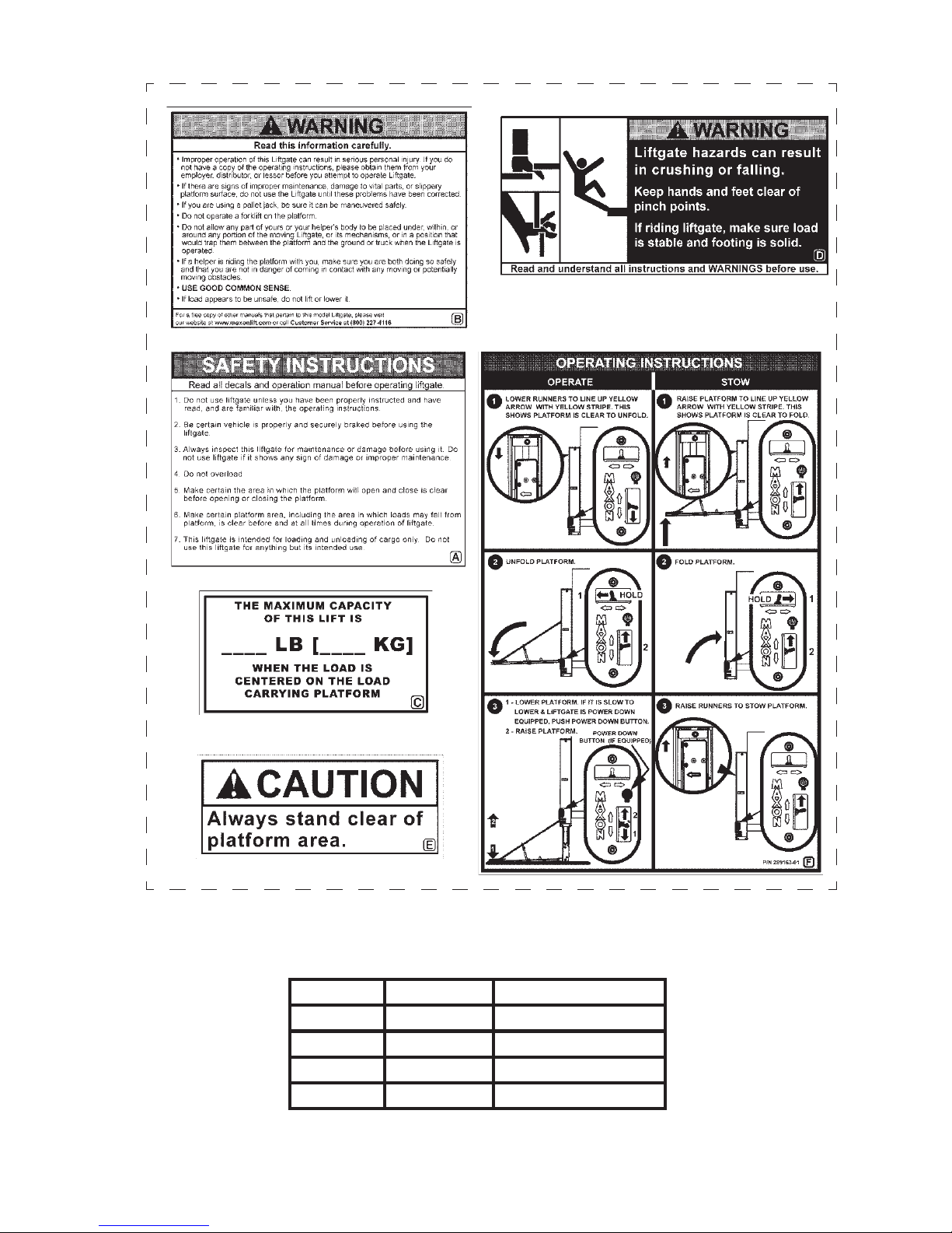
DECAL SHEET
FIG. 9-1
DECAL SHEET PART NUMBERS
TABLE 9-1
(REFER TO TABLE 9-1)
MODEL ORDER P/N DECAL “C”
BMR-35 289163-01 3500 LBS. [1600 KG]
BMR-44 289163-02 4400 LBS. [2000 KG]
BMR-55 289163-03 5500 LBS. [2500 KG]
BMR-66 289163-04 6600 LBS. [3000 KG]
Page 10
10
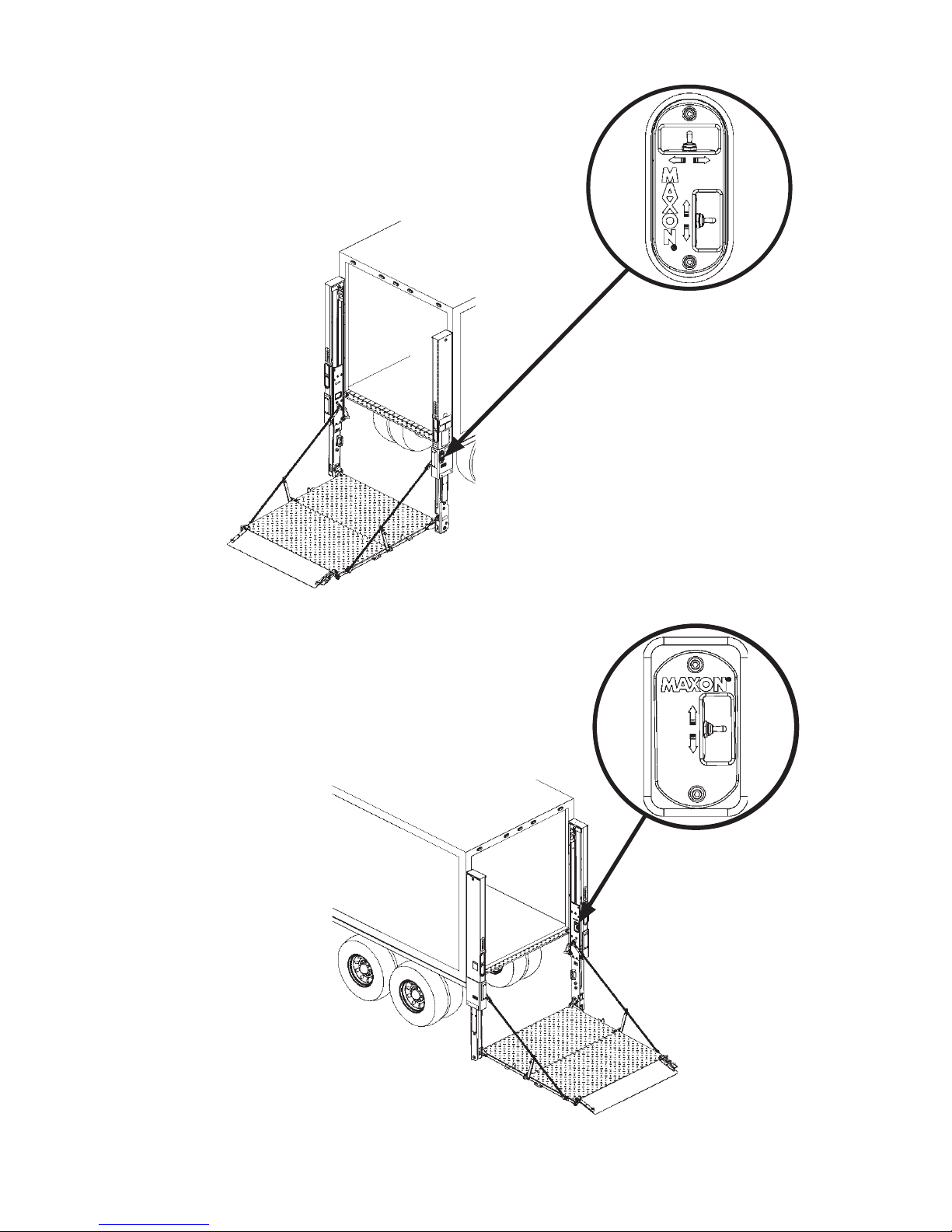
STANDARD CONTROL LOCATIONS
GROUND ACCESS - COLUMN SWITCH
Toggle switches on column switch (FIG. 10-1A)
let operator raise (UP), lower (DOWN), FOLD,
and UNFOLD the platform (FIG. 10-1B) while
standing on the ground.
PLATFORM ACCESS - RUNNER SWITCH
Toggle switch (FIG. 10-2A) on RH runner
lets operator raise (UP) and lower (DOWN) the
platform (FIG. 10-2B) only. Switch stays within
reach when operator rides platform UP and
DOWN.
FIG. 10-1B
FIG. 10-2B
FIG. 10-1A
FIG. 10-2A
Page 11
11
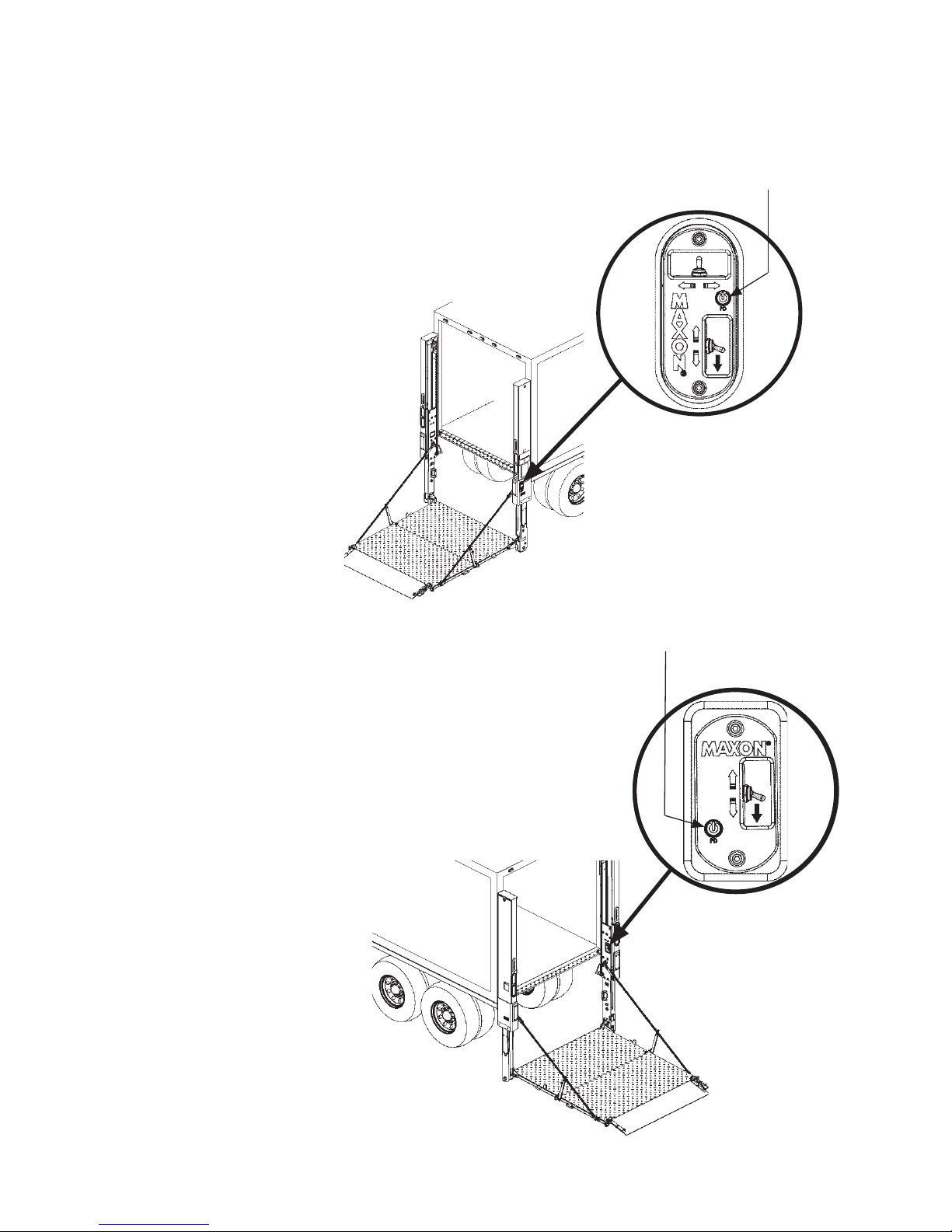
POWER DOWN CONTROLS (IF EQUIPPED)
GROUND ACCESS - COLUMN SWITCH
POWER DOWN button (if equipped) on column
switch (FIG. 11-1A) lets operator lower platform
by pressing the POWER DOWN button once
and pushing and holding the toggle switch
(DOWN) (FIG. 11-1B), while standing on
the ground.
The POWER DOWN button (FIG.
11-1A) illuminates to indicate the power down
function is activated.
FIG. 11-1B
FIG. 11-1A
POWER DOWN
BUTTON
PLATFORM ACCESS - RUNNER SWITCH
POWER DOWN button (if equipped) on runner
switch (FIG. 11-2A) lets operator lower platform
by pressing the POWER DOWN button once
and pushing and holding the toggle switch
(DOWN) (FIG. 11-2B), while standing
on the platform. The POWER DOWN button
(FIG. 11-2A) illuminates to indicate the power
down function is activated.
FIG. 11-2B
FIG. 11-2A
POWER DOWN
BUTTON
Page 12

12
MASTER SELECT
SWITCH
(OFF)
FIG. 12-1C
MASTER SELECT SWITCH
The master select switch (FIGS. 12-1B,
12-2B and 12-2C) applies or removes
battery power from the pump(s). For a single
pump box (FIGS. 12-1A and 12-1B), turn the
MASTER SELECT SWITCH to 1 to operate
Liftgate.
PUMP BOX CONTROLS
SINGLE PUMP BOX
FIG. 12-1A
If the Liftgate is equipped with a dual
pump box, the MASTER SELECT
SWITCH (FIG. 12-1B) can be used to
connect battery power to either pump 1
or pump 2 to power Liftgate. To remove
battery power from pumps 1 and 2, turn
switch OFF (FIG. 12-1C).
MASTER SELECT
SWITCH
(PUMP 1 SELECTED)
FIG. 12-1B
Page 13

13
Keep forklift OFF of platform.
FORKLIFT ADVISOR Y
FIG. 13-1
FIG. 13-2
WARNING
!
Page 14

14
LOWERING THE PLATFORM
FIG. 14-3
To lower platform to the
ground, use column switch as
shown in FIG. 14-3. Release
toggle switch when platform
reaches the ground.
LOADING VEHICLE
COLUMN
DECAL
RUNNER
ARROW
FIG. 14-2A
OPENING THE PLATFORM
COLUMN SWITCH
FIG. 14-1
DOWN
FIG. 14-2B
Push toggle switch to DOWN position (FIG.
14-1) to lower platform until runner arrow and
column decal are about even (FIG. 14-2B).
Platform will be released from the locking
wedges on the Liftgate column. Next, use
column switches 1 and 2 to UNFOLD platform
(FIG. 14-2A). Hold both toggle switches until
platform reaches the unfolded (horizontal)
position and then release the switches.
UNFOLD
DOWN
NOTE: The 2 platform fl ashing lights are fl ashing when platform is unfolding and
unfolded. The lights stop fl ashing when the platform is folded/stowed.
1
2
Page 15

15
OPENING THE RETENTION RAMP
To unfold retention ramp, pull
lock in direction of arrow (FIG.
15-1) and rotate ramp to the
ground (FIG. 15-2).
RAMP
POSITION
LOCK
(PULL TO RELEASE)
FIG. 15-1
FIG. 15-2
RAMP
STOWED
POSITION
Page 16

16
Place all loads as close as
possible to the inboard edge of
the platform with heaviest part
toward the truck body as shown
in FIG. 16-1. Move loads
across the ramp (FIG. 16-1)
to the platform, but never rest
or raise loads on the ramp. If
standing on platform with the
load, stand in the footprint area
shown and comply with the
preceding WARNING.
A load should never extend past the edges of the platform. Do not
place unstable loads on platform and do not allow load to exceed
lifting capacity of Liftgate. If standing on platform, do not allow your
feet to extend beyond inboard edge of platform.
WARNING
!
RAMP
INBOARD
EDGE
LOADING PLATFORM AT GROUND LEVEL
FIG. 16-1
LOADING VEHICLE - Continued
POSITIONING LOAD
Page 17

17
1. Fold ramp until it locks in retention
position (FIG. 17-1B).
3. Carefully move the load into
vehicle (FIG. 17-2).
FIG. 17-1A
STAND CLEAR OF
PLATFORM
(REFER TO DECALS
& PLATES)
RAISING & UNLOADING PLATFORM
RAMP
A ramp in retention position can trip you when stepping over it.
To prevent possible injury, get on the platform before putting the
ramp in retention position.
CAUTION
!
PLATFORM
MOVING LOAD INTO VEHICLE
FIG. 17-2
FIG. 17-1B
RETENTION
POSITION
2. Use runner switch to raise (UP)
platform from ground level to bed
height (FIG. 17-2). Release
switch when platform reaches
bed height.
RUNNER
SWITCH
UP
Page 18

18
FIG. 18-1
LOADING VEHICLE - Continued
RAISING & UNLOADING PLATFORM - Continued
4. Use runner switch to lower
the platform to ground level
(FIG. 18-1).
5. If there are more loads to put
in vehicle, repeat the previous
LOADING VEHICLE steps
for each load. When loading
is fi nished, use STOWING
PLATFORM procedure in this
manual.
INBOARD
EDGE
RUNNER
SWITCH
DOWN
Page 19

19
OPENING THE PLATFORM
UNLOADING VEHICLE
LOWERING THE PLATFORM
FIG. 19-3
To lower platform to the ground,
use runner switch as shown
in FIG. 19-3. Release toggle
switch when platform reaches
the ground.
Push column UP/DOWN toggle switch to
DOWN position (FIG. 19-1) to lower platform
(FIG. 19-2A) until runner arrow and column
decal are about even (FIG. 19-2B). Platform
will be released from the locking wedges on the
Liftgate column. Next, use column switches 1
and 2 to UNFOLD platform (FIG. 19-2A). Hold
both toggle switches until platform reaches the
unfolded (horizontal) position and then release
the switches.
FIG. 19-2A
COLUMN SWITCH
FIG. 19-1
DOWN
FIG. 19-2B
UNFOLD
INBOARD
EDGE
RUNNER
SWITCH
COLUMN
DECAL
RUNNER
ARROW
STAND CLEAR OF
PLATFORM
(REFER TO DECALS
& PLATES)
DOWN
1
2
Page 20

20
OPENING RAMP TO RETENTION POSITION
UNLOADING VEHICLE - Continued
To unfold retention ramp, pull
lock mechanism in direction of
arrow (FIG. 20-1) and lift the
retention ramp until it locks
in the retention position (FIG.
20-2).
FIG. 20-2
STOWED
POSITION
RETENTION
POSITION
A ramp in retention position can trip you when stepping over it. To
prevent possible injury, get on the platform before putting the ramp
in retention position.
CAUTION
!
FIG. 20-1
LOCK
(PULL TO RELEASE)
RAMP
Page 21

21
INBOARD
EDGE
Use runner switch to raise
platform (FIG. 21-1) from ground
level to bed height. Release switch
when platform reaches bed height.
RAISING THE PLATFORM
FIG. 21-1
RUNNER
SWITCH
UP
Page 22

22
INBOARD
EDGE
A load should never extend past the edges of the platform. Do not
place unstable loads on platform and do not allow load to exceed
lifting capacity of Liftgate. If standing on platform, do not allow your
feet to extend beyond inboard edge of platform.
WARNING
!
UNLOADING VEHICLE - Continued
POSITIONING LOAD
PUSHING LOAD ON PLATFORM
FIG. 22-1
Load the platform at bed level
(FIG. 22-1) as follows. Push load
out of the vehicle to correct position on the platform. Place all loads
as close as possible to the inboard
edge of the platform with heaviest
part toward the vehicle body as
shown in FIG. 22-1. If standing on
platform with the load, stand in the
footprint area shown and comply
with the WARNING at the
top of this page.
Pulling the load from vehicle to platform can result in a fall from
platform and serious injury. When unloading vehicle, always push
the load out on the platform.
!
WARNING
Page 23

23
1. Use runner switch to lower platform
to the ground (FIG. 23-1A). Release
switch when platform reaches
ground level.
Before lowering platform, make sure area surrounding platform is
clear of people and objects. If standing on platform, do not allow
your feet to extend beyond inboard edge of platform.
WARNING
!
3. Carefully move load off platform
(FIG. 23-2) and then move it to
a place where it will not become
a hazard for people and other
vehicles. If there is more to
unload from vehicle, repeat
the previous UNLOADING
VEHICLE steps for each load.
When unloading is fi nished,
use STOWING PLATFORM
procedure in this manual.
2. Pull up on lock mechanism
and lower retention ramp
to the ramp position (FIG.
23-1B).
LOWERING & UNLOADING PLATFORM
FIG. 23-1A
FIG. 23-1B
RAMP
POSITION
INBOARD
EDGE
MOVING LOAD OFF PLATFORM
FIG. 23-2
RUNNER
SWITCH
STAND CLEAR OF
PLATFORM
(REFER TO DECALS
& PLATES)
DOWN
Page 24

24
STOW RETENTION RAMP
STOWING PLATFORM
Push retention ramp
to stowed position as
shown in FIGS. 24-1A &
24-1B.
STOWED
POSITION
RETENTION
POSITION
1. Use the column switch to raise (UP)
platform (FIG. 24-2A) until runner arrow
and column decal on LH column are
aligned (FIG. 24-2B).
FIG. 24-1A
FIG. 24-1B
FIG. 24-2A
STOW PLATFORM
RAMP
POSITION
CAUTION
Platform and bottom stops could be damaged if platform is folded
with heel below the column bottom stops. Bottom stops will
interfere with folded platform being raised to up position. Prevent
damage by aligning arrow decals on column & runner before folding platform. Then, platform heel will be above the bottom stops.
UP
COLUMN
DECAL
RUNNER
ARROW
FIG. 24-2B
Page 25

25
Upper locking wedges must be engaged before moving vehicle.
WARNING
!
FIG. 25-1
PLATFORM STOWED IN
UPPER LOCKED POSITION
FIG. 25-2A
2. Hold both column
switches 1 and 2 to FOLD
platform (FIG. 25-1).
3. Use column switch to raise
(UP) platform to upper
locking position as follows
(FIG. 25-2A). Raise platform
until round wedge on each
opener arm is behind the
upper locking wedge on
each column (FIGS. 25-2A &
25-2B).
UPPER LOCKING WEDGE ENGAGED
(CHAIN REMOVED FROM VIEW)
FIG. 25-2B
ROUND
WEDGE
OPENER
ARM
FOLD
UPPER
LOCKING
WEDGE
UP
NOTE: The 2 platform fl ashing lights are fl ashing when platform is unfolding and
unfolded. The lights stop fl ashing when the platform is folded/stowed.
1
2
Page 26

26
CAUTION
!
NOTE: Some Liftgates are equipped with single or dual cart stops.
Cart stops prevent loaded carts from rolling off outboard end
of platform. Single cart stops are 1 section, about the same
as overall width of platform, and operate with one set of
controls. Dual cart stops are 2 identical sections, with a combined width about the same as overall width of platform, and
each is independently operated with separate controls (1 set
of controls per cart stop). The following procedure shows dual
cart stops. A single cart stop operates the same way.
1. At ground level, move load
on platform with cart stops as
shown in FIG. 26-1.
To prevent injuries caused by tripping and falling, make sure
cart stops are closed before walking on and off outboard end of
platform.
NOTE: Cart stops are usually closed when not in use. If you fi nd the
carts stops are already open when rolling a load from the
ground to the platform, you may roll the load over the cart
stop. The cart stop will close temporarily as the load crosses
and reopen when the load is off the cart stop.
USING CART STOPS (IF EQUIPPED)
LOADING PLATFORM AT GROUND LEVEL
(CART STOPS CLOSED)
FIG. 26-1
CART STOPS
Page 27

27
2. Open cart stops by pushing the
cart stop lock down with your
foot (FIG. 27-1B). (FIGS. 27-1A
and 27-1B). Next, position
cart(s) and stand in the footprint
area as shown in FIG. 27-1A.
NOTE: Cart stops are kept open by a cart stop lock.
UNLOADING PLATFORM AT BED LEVEL
(DUAL CART STOPS OPEN)
FIG. 27-2
3. Raise the platform to bed
level (FIG. 27-2). Move the
load off the platform into the
vehicle body (FIG. 27-2).
CART STOPS
OPENING CART STOPS
(RH SIDE OF FLIP OVER)
FIG. 27-1B
VEHICLE
BODY
PLATFORM
LOADING PLATFORM AT GROUND LEVEL
(CART STOPS OPEN)
FIG. 27-1A
CART STOP LOCK
(DUAL CART
STOPS ONLY)
CART STOP
LOCK
Page 28

28
CART STOP LOCK
(DUAL CART
STOPS ONLY)
4. When loading the plat-
form at bed level, make
sure cart stops are open
(FIG. 28-1). Push load
out of the vehicle. Place
all loads as close as
possible to the edge of
the cart stops as shown
in FIG. 28-1. If standing
on platform with the load,
stand in the footprint
area shown and comply with the WARNING
shown above.
Pulling the load from vehicle to platform can result in a fall from
platform and serious injury. When unloading vehicle, always
push the load out on the platform.
WARNING
!
5. Unload platform with cart
stops at ground level as
follows. Make sure cart
stops are closed before
moving load off the platform (FIG. 28-2). To close,
push the cart stop lock
down. Then, step on cart
stop until closed (FIG.
28-2). Move load off the
platform as shown in FIG.
28-2.
NOTE: Cart stops are kept
closed by a cart stop
lock (FIG. 28-2).
USING CART STOPS (IF EQUIPPED) - Continued
LOADING PLATFORM AT BED LEVEL
(DUAL CART STOPS OPEN)
FIG. 28-1
VEHICLE
BODY
PLATFORM
CART STOPS
CART
STOPS
CART STOP
LOCK
UNLOADING PLATFORM AT GROUND
(DUAL CART STOPS CLOSED)
FIG. 28-2
Page 29

29
NOTE: Some Liftgates are equipped with auto cart stops. Auto cart
stops open and close automatically depending on the position
of the liftgate. The following procedure shows auto cart stops.
1. Move load on platform on the
ground as shown in FIG. 29-1.
USING AUTO CART STOPS (IF EQUIPPED)
LOADING PLATFORM AT GROUND LEVEL
(AUTO CART STOP CLOSED)
FIG. 29-1
AUTO CART
STOP
Page 30

30
AUTO CART STOP OPEN
FIG. 30-1
2. Stand in the footprint area
as shown (FIG. 30-1) before
raising the platform.
NOTE: Auto cart stop is opened
by raising the platform
(FIG. 30-1).
UNLOADING PLATFORM AT BED LEVEL
(AUTO CART STOP OPEN)
FIG. 30-2
3. Raise the platform to bed
level (FIG. 30-2). Move the
load off the platform into the
vehicle body (FIG. 30-2).
VEHICLE
BODY
PLATFORM
USING AUTO CART STOPS (IF EQUIPPED)
- Continued
AUTO CART
STOP
Page 31

31
Pulling the load from vehicle to platform can result in a fall from
platform and serious injury. When unloading vehicle, always
push the load out on the platform.
WARNING
!
AUTO CART STOP CLOSED
FIG. 31-2
5. Unload platform with auto cart
stop at ground level as follows.
Move load off the platform as
shown in FIG. 31-2.
NOTE: When loading the platform
at bed level, auto cart stop
is open (FIG. 31-1).
LOADING PLATFORM AT BED LEVEL
(AUTO CART STOP OPEN)
FIG. 31-1
PLATFORM
AUTO
CART STOP
AUTO CART
STOP
NOTE: Auto cart stop is closed
when platform is on the
ground (FIG. 31-2).
VEHICLE
BODY
4. Push load out of the ve-
hicle and place all loads
as close as possible to the
edge of the cart stop(s)
as shown in FIG. 31-1.
If standing on platform
with the load, stand in the
footprint area shown and
comply with the WARNING
shown above.
Page 32

32
1. Use column switch to lower (DOWN) platform
until it rests on bottom stops (FIG. 32-1). Release
switch when top edge of closed platform is below
bed height and dock level, and in the lower locking
position (FIG. 32-1). Now, loads can be moved
between dock and vehicle without using Liftgate.
LOWER LOCKING POSITION
FIG. 32-1
DOCK
Use dock plate for moving loads between dock and vehicle. Dock
plate must be supported by dock and vehicle fl oor. It must not
rest on Liftgate platform.
CAUTION
!
LOWER PLATFORM BELOW DOCK LEVEL
DOCK LOADING & UNLOADING
VEHICLE
FLOOR
PLATFORM
NOTE: Platform may be lowered with
vehicle backed up to dock.
DOWN
Page 33

33
Upper locking wedges must be engaged before moving vehicle.
WARNING
!
PLATFORM STOWED IN
UPPER LOCKED POSITION
FIG. 33-1A
UPPER LOCKING WEDGE ENGAGED
(CHAIN REMOVED FROM VIEW)
FIG. 33-1B
ROUND
WEDGE
OPENER
ARM
UPPER
LOCKING
WEDGE
UP
2. When fi nished loading and
unloading from the dock,
use column switch to raise
(UP) platform to upper
locking position as follows
(FIG. 33-1A). Raise platform
until round wedge on each
opener arm is behind the
upper locking wedge on
each column (FIGS. 33-1A &
33-1B).
Page 34

 Loading...