

Maxon TE-20, 72-150 Installation Manual
M-12-04
REV. F
SEPTEMBER 2015
INSTALLATION MANUAL
TE-20 & 72-150
To nd maintenance & parts information for your TE-20 & 72-150 Liftgate,
go to www.maxonlift.com. Click the PRODUCTS, TUK-A-WAY and TE-20
or 72-150 buttons. Open the Maintenance Manual in the PRODUCT DOCU-
MENTATION window.
© 2015 MAXON LIFT CORP.

TABLE OF CONTENTS
SUMMARY OF CHANGES: M-12-04, REVISION F ............................................................. 4
WARNINGS ........................................................................................................................... 5
SAFETY INSTRUCTIONS .................................................................................................... 6
NOTICE ................................................................................................................................. 6
72-150 & TE-20 LIFTGATE COMPONENTS ........................................................................ 7
PARTS BOX FOR 72-150 GRAVITY DOWN (96” WIDE, PAINTED FINISH) ....................... 8
PARTS BOX FOR 72-150 & TE-20 GRAVITY DOWN
(96” WIDE, GALVANIZED FINISH, 12 VOLT & 24 VOLT) ..................................................... 9
PARTS BOX FOR 72-150 POWER DOWN
(96” WIDE, PAINTED FINISH) ............................................................................................ 10
PARTS BOX FOR 72-150 & TE-20 POWER DOWN
(96” WIDE, GALVANIZED FINISH) ......................................................................................11
VEHICLE REQUIREMENTS ............................................................................................... 12
PLATFORM WITH RAMP FLIPOVER ................................................................................. 14
STEP 1 - INSTALL EXTENSION PLATES .......................................................................... 16
WELD PAINTED EXTENSION PLATE TO VEHICLE .......................................... 17
BOLT GALVANIZED EXTENSION PLATE TO VEHICLE .................................... 20
WELD GALVANIZED EXTENSION PLATE TO VEHICLE ................................... 22
WELD INSTALLATION BRACKETS .................................................................... 23
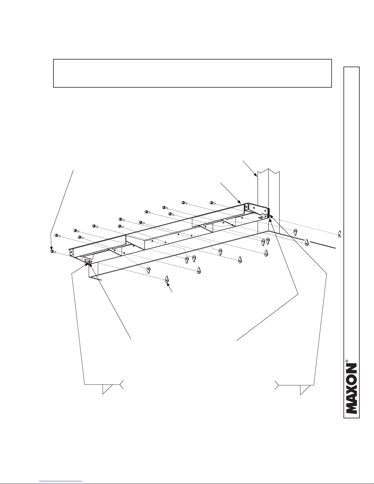
STEP 2 - WELD LIFTGATE TO VEHICLE ......................................................................... 24
STEP 3 - ATTACH OPTIONAL BATTERY BOX & FRAME TO VEHICLE (IF EQUIPPED) . 27
STEP 4 - RUN POWER CABLE .......................................................................................... 35
STEP 5 - CONNECT POWER CABLE ................................................................................ 37
STEP 6 - CONNECT GROUND CABLE (RECOMMENDED) ............................................. 39
STEP 7 - INSTALL CONTROL SWITCH ............................................................................. 40
STEP 8 - ADD HYDRAULIC FLUID .................................................................................... 43

STEP 9 - CONNECT POWER CABLE TO BATTERY ......................................................... 45
STEP 10 - REMOVE LOCKING ANGLE AND CHECK FOR INTERFERENCE .................. 46
STEP 11 - BOLT PLATFORM OPENER TO LIFTGATE ...................................................... 51
STEP 12 - PLATFORM ADJUSTMENT (IF REQUIRED) .................................................... 54
STEP 13 - FINISH WELDING LIFTGATE TO VEHICLE ..................................................... 57
STEP 14 - ADJUST SAFETY HOOK (IF REQUIRED) ....................................................... 58
STEP 15 - WELD ON LOCK BRACKET (IF EQUIPPED) ................................................... 59
STEP 16 - VEHICLE TAILLIGHT POSITIONING (IF REQUIRED) ...................................... 60
ATTACH DECALS ............................................................................................................... 61
TOUCHUP PAINTED OR GALVANIZED FINISH ............................................................... 63
HYDRAULIC SYSTEM DIAGRAMS ................................................................................... 64
HYDRAULIC SCHEMATIC (GRAVITY DOWN) ................................................................... 64
HYDRAULIC SCHEMATIC (POWER DOWN) .................................................................... 65
ELECTRICAL SYSTEM DIAGRAMS ................................................................................. 66
ELECTRICAL SCHEMATIC (GRAVITY DOWN) ................................................................. 66
ELECTRICAL SCHEMATIC (POWER DOWN) ................................................................... 67
OPTIONS ........................................................................................................................... 68
OPTIONAL LIFTGATE COMPONENTS .............................................................................. 68

SUMMARY OF CHANGES: M-12-04, REVISION F
PAGE DESCRIPTION OF CHANGE
COVER Updated REV and date of release.
6
44 Removed AMSOIL from the table of recommended hydraulic oil.
68 Removed LVTS options from the OPTIONS table.
Added note to installers to ensure that trucks and trailers are equipped with grab
handles if needed.
11921 Slauson Ave. Santa Fe Springs, CA. 90670 (800) 227-4116 FAX (888) 771-7713
4
Comply with the following WARNINGS and SAFETY INSTRUCTIONS while installing
Liftgates. See Operation Manual for operating safety requirements.
WARNINGS
• Do not stand, or allow obstructions, under the platform when lowering the Liftgate. Be sure your
feet are clear of the Liftgate.
• Keep ngers, hands, arms, legs, and feet clear of moving Liftgate parts (and platform
edges) when operating the Liftgate.
• Correctly stow platform when not in use. Extended platforms could create a hazard for
people and vehicles passing by.
• Make sure vehicle battery power is disconnected while installing Liftgate. Connect vehicle
battery power to the Liftgate only when installation is complete or as required in the installation
instructions.
• If it is necessary to stand on the platform while operating the Liftgate, keep your feet and any
objects clear of the inboard edge of the platform. Your feet or objects on the platform can become
trapped between the platform and the Liftgate extension plate.
• Never perform unauthorized modications on the Liftgate. Modications may result in early failure
of the Liftgate and may create hazards for Liftgate operators and maintainers.
• Recommended practices for welding on steel parts are contained in the current AWS (American
Welding Society) D1.1 Structural Welding Code - Steel. Damage to Liftgate and/or vehicle, and
personal injury can result from welds that are done incorrectly.
!
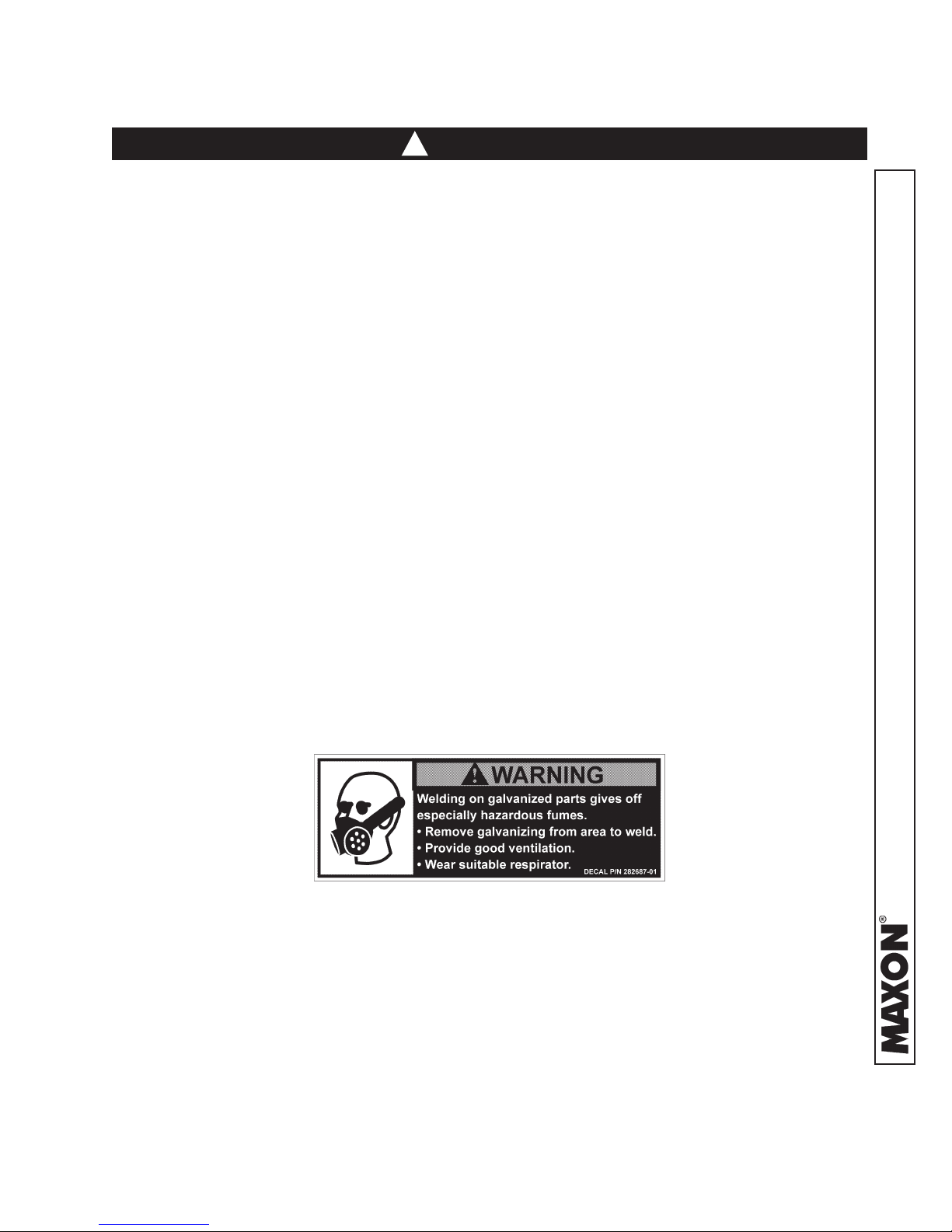
WARNING
• Welding on galvanized parts gives off especially hazardous fumes. Comply with WARNING decal
on the galvanized part (
adequate ventilation, and wear suitable respirator.
FIG. 5-1). To minimize hazard remove galvanizing from weld area, provide
FIG. 5-1
11921 Slauson Ave. Santa Fe Springs, CA. 90670 (800) 227-4116 FAX (888) 771-7713
5

SAFETY INSTRUCTIONS
• Read and understand the instructions in this Installation Manual before installing Liftgate.
• Before operating the Liftgate, read and understand the operating instructions in Operation
Manual.
• Comply with all WARNING and instruction decals attached to the Liftgate.
• Keep decals clean and legible. If decals are illegible or missing, replace them. Free replacement
decals are available from Maxon Customer Service.
• Consider the safety and location of bystanders and location of nearby objects when operating the
Liftgate. Stand to one side of the platform while operating the Liftgate.
• Do not allow untrained persons to operate the Liftgate.
• Wear appropriate safety equipment such as protective eyeglasses, faceshield and clothing while
performing maintenance on the Liftgate and handling the battery. Debris from drilling and contact
with battery acid may injure unprotected eyes and skin.
• Be careful working by an automotive type battery. Make sure the work area is well ventilated and
there are no ames or sparks near the battery. Never lay objects on the battery that can short the
terminals together. If battery acid gets in your eyes, immediately seek rst aid. If acid gets on your
skin, immediately wash it off with soap and water.
• If an emergency situation arises (vehicle or Liftgate) while operating the Liftgate, release the control switch to stop the Liftgate.
SAFETY INSTRUCTIONS
• A correctly installed Liftgate operates smoothly and reasonably quiet. The only noticeable noise
during operation comes from the power unit while the platform is raised and lowered. Listen for
scraping, grating and binding noises and correct the problem before continuing to operate Liftgate.
NOTICE
NOTICE
• Maxon Lift is responsible for the instructions to correctly install MAXON Liftgates on
trucks or trailers only.
• Liftgate installers, not Maxon Lift, are responsible for reviewing and complying with all
applicable Federal, State, and Local regulations pertaining to the trailer or truck.
• Installers of the liftgate should ensure that all trucks and trailers are equipped with grab
handles as needed.
11921 Slauson Ave. Santa Fe Springs, CA. 90670 (800) 227-4116 FAX (888) 771-7713
6
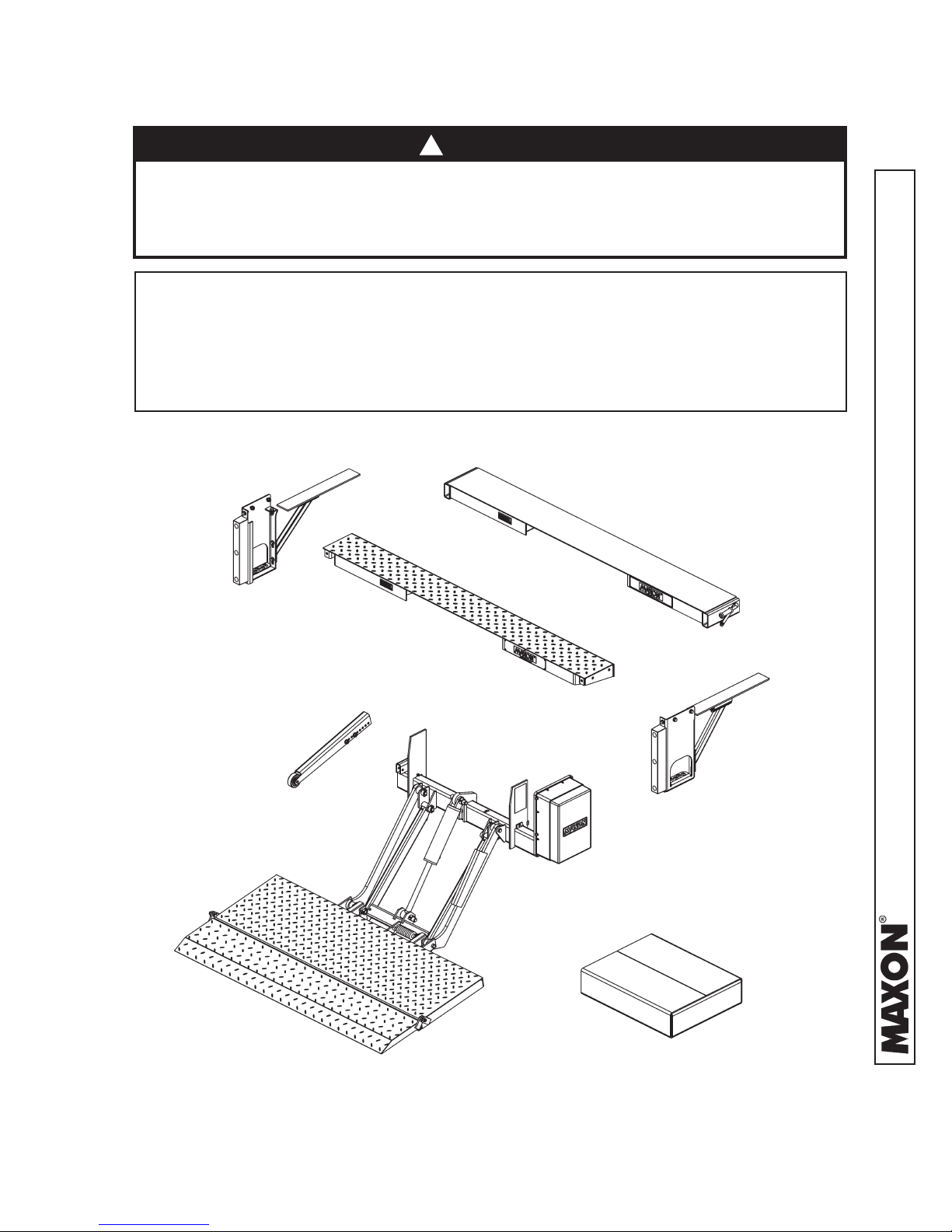
72-150 & TE-20 LIFTGATE COMPONENTS
!
CAUTION
Prevent injuries and equipment damage. Before cutting the shipping straps
from the Liftgate, put Liftgate on level ground that will support at least 1500
pounds. Be careful lifting and moving components (such as extension plate)
after shipping straps are removed.
NOTE: Make sure you have all components and parts before you start installing Lift-
gate. Compare parts in the part box and each kit box with packing list closed
in each box. If parts and components are missing or incorrect, call:
Maxon Customer Service
Call (800) 227-4116 or
Send e-mail to customersupport@maxonlift.com
WELD-ON EXTENSION PLATE
(PAINTED)
BOLT-ON STEP
(GALVANIZED
OR PAINTED)
BOLT-ON EXTENSION PLATE
(GALVANIZED OR PAINTED)
OPENER
BOLT-ON STEP
(GALVANIZED
OR PAINTED)
11921 Slauson Ave. Santa Fe Springs, CA. 90670 (800) 227-4116 FAX (888) 771-7713
PARTS BOX
72-150 & TE-20 COMPONENTS
FIG. 7-1
7

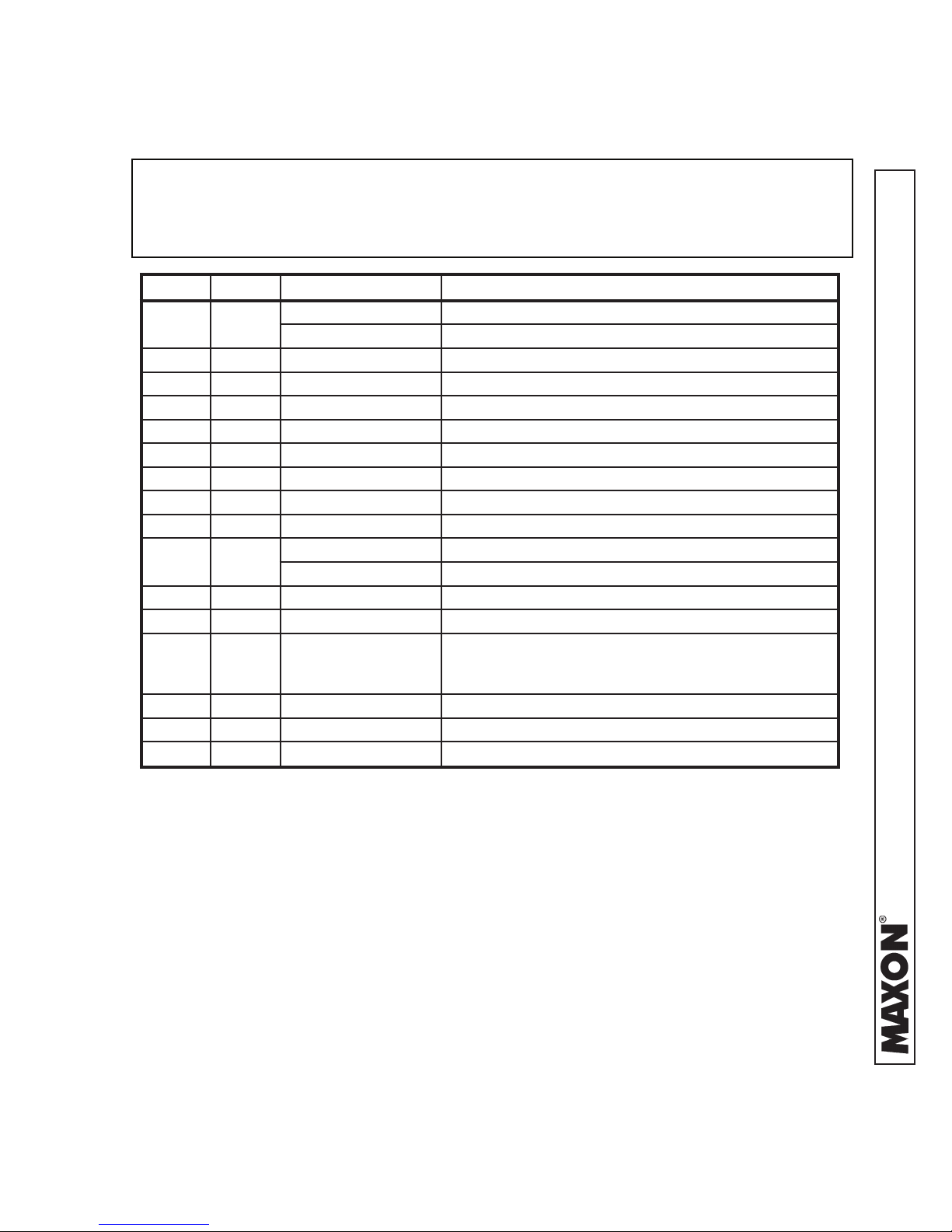
PARTS BOX FOR 72-150 GRAVITY DOWN
(96” WIDE, PAINTED FINISH)
NOTE: To nd maintenance & parts information for your TE-20 & 72-150 Liftgate,
go to www.maxonlift.com. Click the PRODUCTS, TUK-A-WAY and TE-20
or 72-150 button. Open the Maintenance Manual in the PRODUCT DOCU-
MENTATION window.
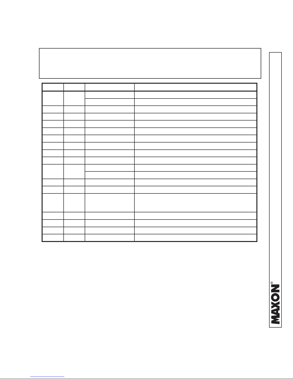
ITEM QTY. PART NUMBER DESCRIPTION
REF 1 269661-01 PARTS BOX, 72-150 GRAVITY DOWN (PAINTED)
1 4 030458 SCREW TAPPING #10 X 1/2” LG.
2 7 050079 CLIP, FRAME
3 1 055011 RUBBER HANDLE
4 1 203417 RENTAL LOCK BRACKET, 6-1/2" LG.
5 1 203570 INNER BRACKET, 1" LG. (USE WITH RENTAL LOCK)
6 1 125674 CLAMP, JIFFY #130
7 10 205780 TIE, PLASTIC, 7" LG.
8 8 206864 TIE, PLASTIC, 12-14" LG.
9 3 214663 CLAMP, #8 RUBBER LOOM
10 1 215345 SPRING, EXTENSION, 2 1/2” LG.
11 2 251333 SHIM, 1/8" X 2" X 2" LG.
12 1 264422 CABLE ASSY, 175 AMPS, 38’ LG.
13 1 269641-01 KIT, MANUAL & DECAL 72-150
13A 1 M-12-04 MANUAL, INSTALLATION 72-150/TE-20
13B 1 M-12-05 MANUAL, OPERATION 72-150/TE-20
REFER TO DECAL
13C -
14 1 267959-01 MOLDED SWITCH ASSY
15 2 900057-5 SCREW, SELF TAPPING, #10-24 X 1” LG.
16 1 906497-02 LUG, 2GA, COPPER
PAGES IN THIS
MANUAL
DECALS
TABLE 8-1
8
11921 Slauson Ave. Santa Fe Springs, CA. 90670 (800) 227-4116 FAX (888) 771-7713
PARTS BOX FOR 72-150 & TE-20 GRAVITY DOWN
(96” WIDE, GALVANIZED FINISH, 12 VOLT & 24 VOLT)
NOTE: To nd maintenance & parts information for your TE-20 & 72-150 Liftgate,
go to www.maxonlift.com. Click the PRODUCTS, TUK-A-WAY and TE-20
or 72-150 button. Open the Maintenance Manual in the PRODUCT DOCU-
MENTATION window.
ITEM QTY. PART NUMBER DESCRIPTION
REF 1
1 4 030458 SCREW TAPPING #10 X 1/2” LG.
2 7 050079 CLIP, FRAME
3 1 125674 CLAMP, JIFFY #130
4 10 205780 TIE, PLASTIC, 7" LG.
5 2 206864 TIE, PLASTIC, 12-14" LG.
6 3 214663 CLAMP, #8 RUBBER LOOM
7 2 251333 SHIM, 1/8" X 2" X 2" LG.
8 1 264422 CABLE ASSY, 175 AMPS, 38’ LG.
9 1
9A 1 M-12-04 MANUAL, INSTALLATION 72-150/TE-20
9B 1 M-12-05 MANUAL, OPERATION 72-150/TE-20
9C -
10 1 267959-01 MOLDED SWITCH ASSY
11 2 900057-5 SCREW, SELF TAPPING, #10-24 X 1” LG.
12 1 906497-02 LUG, 2GA, COPPER
269642-01 PARTS BOX, 72-150 GRAVITY DOWN (GALVANIZED)
269642-03 PARTS BOX, TE-20 GRAVITY DOWN (GALVANIZED)
269641-01 KIT, MANUAL & DECAL 72-150
269641-02 KIT, MANUAL & DECAL TE-20
REFER TO DECAL
PAGES IN THIS
MANUAL
DECALS
11921 Slauson Ave. Santa Fe Springs, CA. 90670 (800) 227-4116 FAX (888) 771-7713
TABLE 9-1
9

PARTS BOX FOR 72-150 POWER DOWN
(96” WIDE, PAINTED FINISH)
NOTE: To nd maintenance & parts information for your TE-20 & 72-150 Liftgate,
go to www.maxonlift.com. Click the PRODUCTS, TUK-A-WAY and TE-20
or 72-150 button. Open the Maintenance Manual in the PRODUCT DOCU-
MENTATION window.
ITEM QTY. PART NUMBER DESCRIPTION
REF 1 269661-03 PARTS BOX, 72-150 GRAVITY DOWN (PAINTED)
1 4 030458 SCREW TAPPING #10 X 1/2” LG.
2 7 050079 CLIP, FRAME
3 1 055011 RUBBER HANDLE
4 1 203417 RENTAL LOCK BRACKET, 6-1/2" LG.
5 1 203570 INNER BRACKET, 1" LG. (USE WITH RENTAL LOCK)
6 1 125674 CLAMP, JIFFY #130
7 10 205780 TIE, PLASTIC, 7" LG.
8 8 206864 TIE, PLASTIC, 12-14" LG.
9 3 214663 CLAMP, #8 RUBBER LOOM
10 1 215345 SPRING, EXTENSION, 2 1/2” LG.
11 2 251333 SHIM, 1/8" X 2" X 2" LG.
12 1 264422 CABLE ASSY, 175 AMPS, 38’ LG.
13 1 269641-01 KIT, MANUAL & DECAL 72-150
13A 1 M-12-04 MANUAL, INSTALLATION 72-150/TE-20
13B 1 M-12-05 MANUAL, OPERATION 72-150/TE-20
REFER TO DECAL
13C -
14 1 264951-04 MOLDED SWITCH & CABLE ASSEMBLY
15 2 900057-5 SCREW, SELF TAPPING, #10-24 X 1” LG.
16 1 906497-02 LUG, 2GA, COPPER
PAGES IN THIS
MANUAL
DECALS
TABLE 10-1
10
11921 Slauson Ave. Santa Fe Springs, CA. 90670 (800) 227-4116 FAX (888) 771-7713
PARTS BOX FOR 72-150 & TE-20 POWER DOWN
(96” WIDE, GALVANIZED FINISH)
NOTE: To nd maintenance & parts information for your TE-20 & 72-150 Liftgate,
go to www.maxonlift.com. Click the PRODUCTS, TUK-A-WAY and TE-20
or 72-150 button. Open the Maintenance Manual in the PRODUCT DOCU-
MENTATION window.
ITEM QTY. PART NUMBER DESCRIPTION
REF 1
1 4 030458 SCREW TAPPING, #10 X 1/2” LG.
2 7 050079 CLIP, FRAME
3 1 125674 CLAMP, JIFFY #130
4 10 205780 TIE, PLASTIC, 7" LG.
5 2 206864 TIE, PLASTIC, 12-14" LG.
6 3 214663 CLAMP, #8 RUBBER LOOM
7 2 251333 SHIM, 1/8" X 2" X 2" LG.
8 1 264422 CABLE ASSY, 175 AMPS, 38’ LG.
9 1
9A 1 M-12-04 MANUAL, INSTALLATION 72-150/TE-20
9B 1 M-12-05 MANUAL, OPERATION 72-150/TE-20
9C -
10 1 264951-04 MOLDED SWITCH & CABLE ASSEMBLY
11 1 202406 BRASS ELBOW 1/4” X 1/4”
12 2 900057-5 SCREW, SELF TAPPING, #10-24 X 1” LG.
13 1 906497-02 LUG, 2GA, COPPER
269642-02 PARTS BOX, TE-20 POWER DOWN (GALVANIZED)
269642-04 PARTS BOX, 72-150 POWER DOWN (GALVANIZED)
269641-01 KIT, MANUAL & DECAL, 72-150
269641-02 KIT, MANUAL & DECAL, TE-20
REFER TO DECAL
PAGES IN THIS
MANUAL
DECALS
TABLE 11-1
11921 Slauson Ave. Santa Fe Springs, CA. 90670 (800) 227-4116 FAX (888) 771-7713
11
VEHICLE REQUIREMENTS
NOTE: The maximum (unloaded) operating vehicle body bed height for the 72-150
& TE-20 Liftgates equipped with wedge ipover or ramp ipover is 54”.
The minimum height for the 72-150 & TE-20 Liftgates equipped with
wedge ipover is 44” (loaded). The minimum height for 72-150 and TE20 Liftgates equipped with ramp ipover is 38” (loaded). Do not install
this Liftgate on vehicle bodies equipped with swing open doors.
NOTE: Make sure vehicle is parked on level ground while preparing vehicle and
installing Liftgate.
NOTE: Dimensions are provided as a reference only for tting Liftgate to vehicle
body.
NOTE: Measure the width of the Liftgate and the width of the vehicle body before
you start doing this procedure. Ensure the Liftgate is the correct width for
vehicle.
The vehicle clearance dimensions and vehicle chassis cutout dimensions, for
72-150 and TE-20 Liftgates, are shown on the pages that follow. Dimensions
are given for high bed and low bed installations.
11921 Slauson Ave. Santa Fe Springs, CA. 90670 (800) 227-4116 FAX (888) 771-7713
12
VEHICLE REQUIREMENTS - Continued
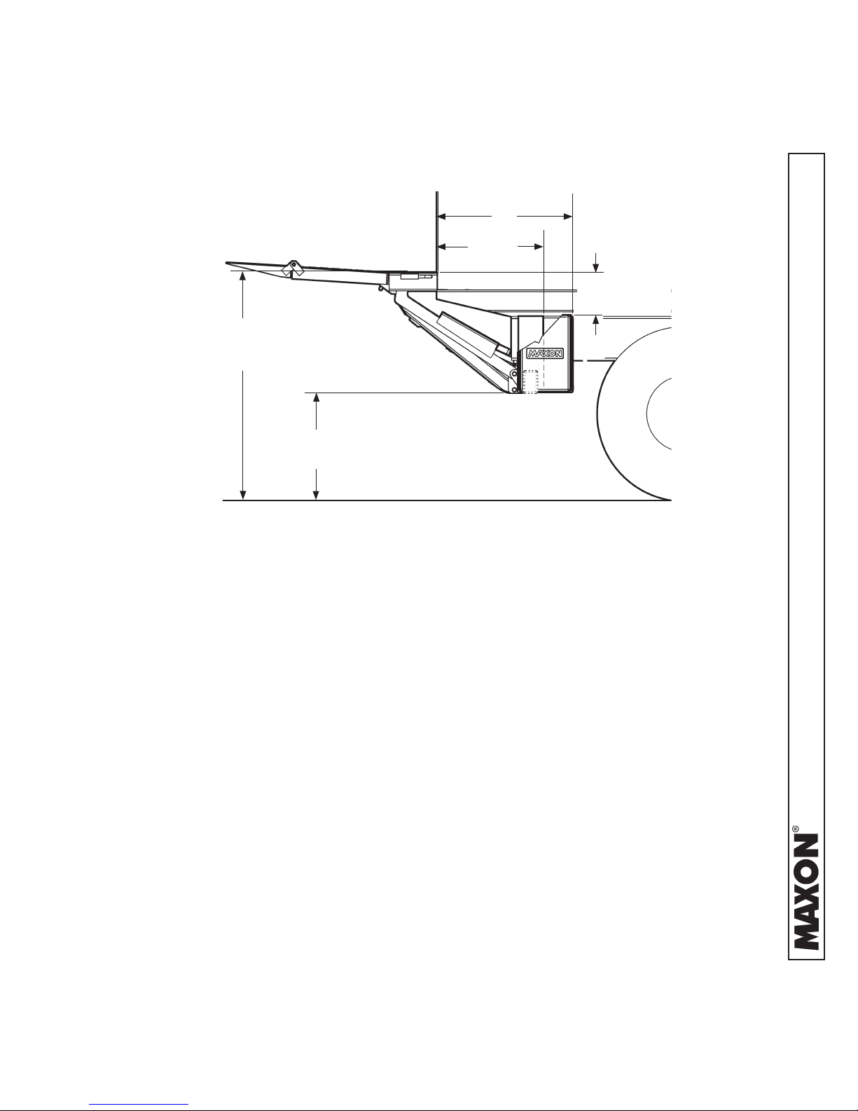
PLATFORM WITH WEDGE FLIPOVER
29”
22-1/2”
11 9/16”
54” MAX. (UNLOADED)
44” MIN. (LOADED)
24-1/2” MAX.
14-3/4” MIN.
CLEARANCES FOR TE-20 & 72-150, HIGH BED HEIGHT ONLY
FIG. 13-1
11921 Slauson Ave. Santa Fe Springs, CA. 90670 (800) 227-4116 FAX (888) 771-7713
13

VEHICLE REQUIREMENTS - Continued
PLATFORM WITH RAMP FLIPOVER
29”
22-1/2”
11
54” MAX. (UNLOADED)
42” MIN. (LOADED)
24-1/8” MAX.
12-1/8” MIN.
CLEARANCES FOR TE-20 & 72-150 ON HIGH BED HEIGHT
FIG. 14-1
32”
24-1/4”
9-1/2
44” MAX. (UNLOADED)
38” MIN. (LOADED)
16-1/2” MAX.
10-1/2” MIN.
11921 Slauson Ave. Santa Fe Springs, CA. 90670 (800) 227-4116 FAX (888) 771-7713
CLEARANCES FOR TE-20 & 72-150 ON LOW BED HEIGHT
FIG. 14-2
14
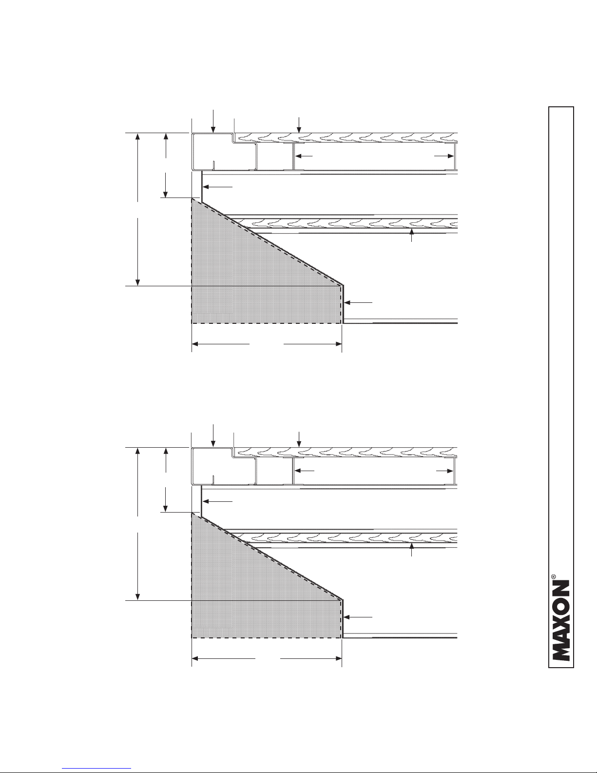
VEHICLE REQUIREMENTS - Continued
REAR SILL
6”
BODY FRAME
10”
PLATFORM CLEARANCE
CUTOUT AREA
(WITHIN DASHED LINES)
BODY FLOOR
BODY CROSS MEMBERS
SPACER
TRUCK FRAME
17”
VEHICLE FRAME CUT FOR TE-20 & 72-150 (44” TO 54” BED HEIGHTS)
FIG. 15-1
REAR SILL
5-1/2”
BODY FRAME
9”
PLATFORM CLEARANCE
CUTOUT AREA
(WITHIN DASHED LINES)
BODY FLOOR
BODY CROSS MEMBERS
SPACER
TRUCK FRAME
17”
VEHICLE FRAME CUT FOR TE-20 & 72-150 (38” TO 46” BED HEIGHTS)
FIG. 15-2
11921 Slauson Ave. Santa Fe Springs, CA. 90670 (800) 227-4116 FAX (888) 771-7713
15

STEP 1 - INSTALL EXTENSION PLATES
NOTE: TE-20 Liftgates may be equipped with two types of extensions plates. The
painted extension plate (FIG. 16-1) does not have bolt holes and is welded
on. Weld-on support straps and spacers (ats), provided with parts bags,
must be used. The galvanized extension plate (FIG. 16-2) has bolt holes
so it can be bolted to vehicle body. GRADE 8 bolts are required. MAXON
recommends getting the optional extension plate hardware kit listed in OP-
TIONS section. It also has holes for bolt-on installation brackets, provided
with parts bags. Refer to the following instructions for installing painted
extension plates or galvanized extension plates.
PAINTED WELD-ON EXTENSION PLATE
FIG. 16-1
GALVANIZED BOLT-ON EXTENSION PLATE
FIG. 16-2
11921 Slauson Ave. Santa Fe Springs, CA. 90670 (800) 227-4116 FAX (888) 771-7713
16
STEP 1 - INSTALL EXTENSION PLATES - Continued
WELD PAINTED EXTENSION PLATE TO VEHICLE
CAUTION
To protect the original paint system, a 3” wide area of paint must be removed
from all sides of the weld area before welding.
NOTE: Before welding extension plate to vehicle body, make sure:
• Inboard edge of extension plate is ush with the top of sill on vehicle body.
• Top surface of extension plate is level with the ground.
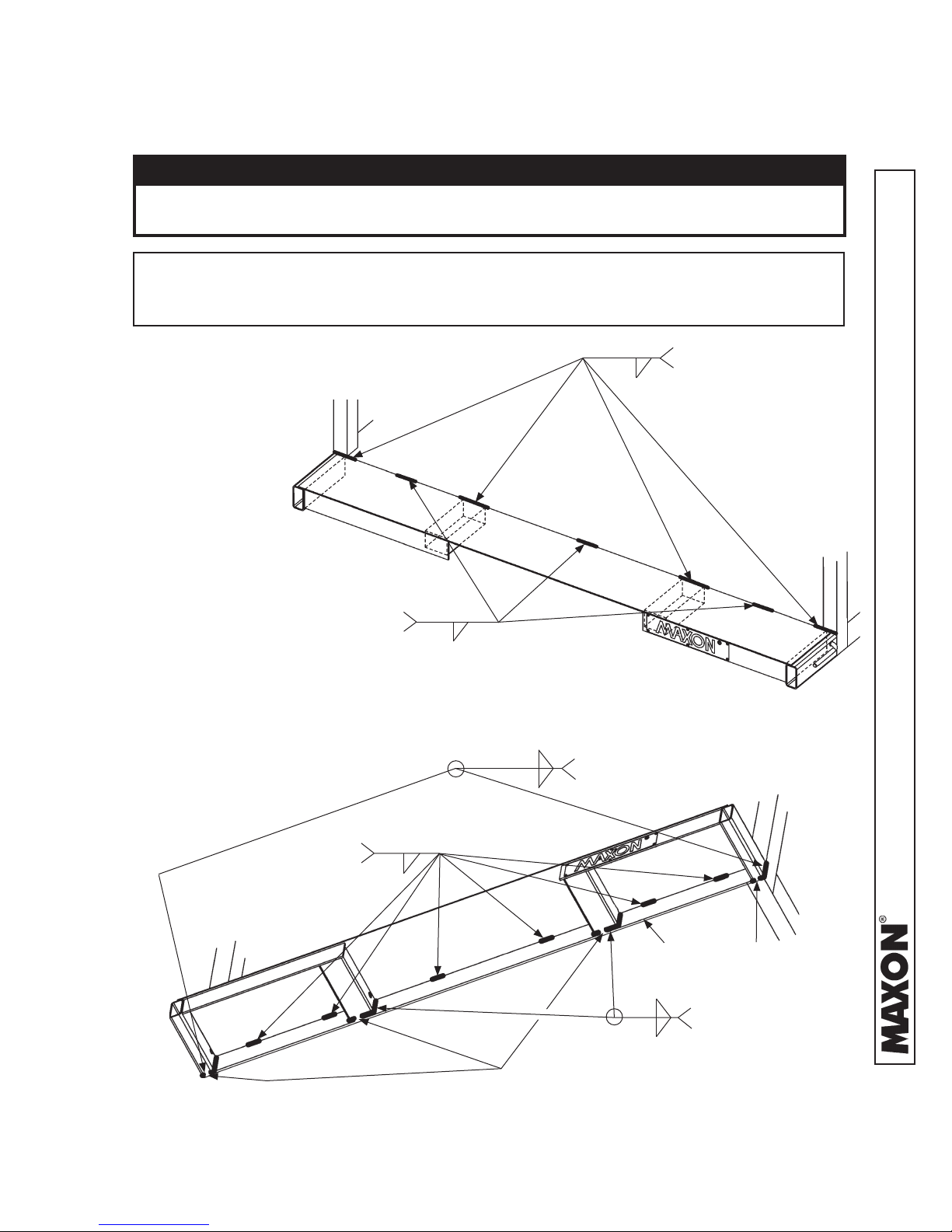
1. Center the extension
plate on vehicle body.
Weld the extension
plate to vehicle body
sill as shown in FIGS.
17-1 and 17-2
EQUALLY SPACED
BETWEEN 4” LG WELDS
EXTENSION PLATE WELDS - VIEWED FROM ABOVE
2” LG (TYP.)
1/4”
FIG. 17-1
1/4”
1/4”
1/4”
2 PLACES, MAKE 1” GAP
WHERE SHOWN
5” LG (TYP.), 4 PLACES
CENTER OVER WIDTH
OF 2 CHANNELS AND 2
TUBES (UNDER FLOORPLATE - SEE DASHED
LINES)
2” LG, 6 PLACES
EQUAL SPACING
(TYP.)
EXTENSION PLATE WELDS - VIEWED FROM UNDERNEATH
1/4”
1” GAP
FIG. 17-2
17
SILL
(PART OF
VEHICLE BODY)
1/4”
1/4”
1” GAP
2 PLACES, MAKE 1”
GAP WHERE SHOWN
11921 Slauson Ave. Santa Fe Springs, CA. 90670 (800) 227-4116 FAX (888) 771-7713
STEP 1 - INSTALL EXTENSION PLATES - Continued
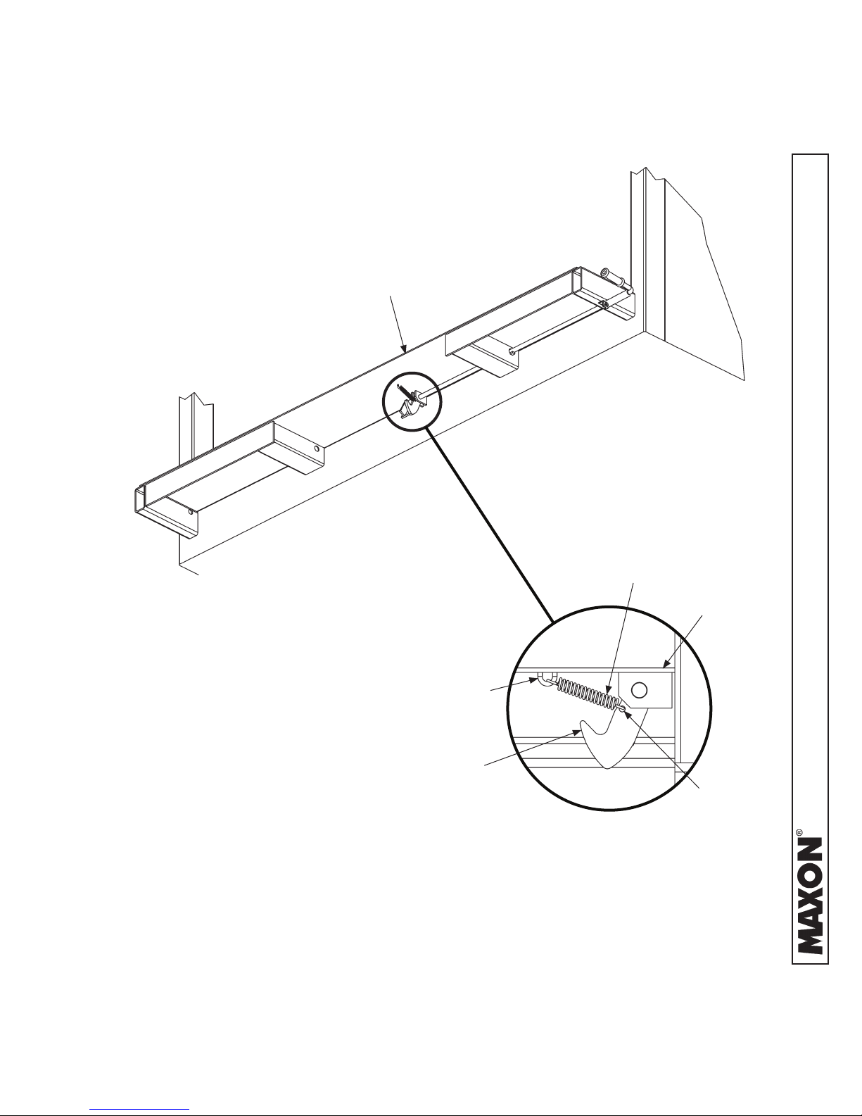
2. Get extension spring (FIG. 18-1A) from
parts box. Hook one end of spring in loop
(FIG. 18-1A) under extension plate (FIG.
18-1). Next, hook opposite end of spring
in eye of the safety hook (FIG. 18-1A).
EXTENSION PLATE
EXTENSION SPRING PLACEMENT
FIG. 18-1
LOOP
SAFETY
HOOK
EXTENSION
SPRING
EXTENSION
PLATE
EYE
11921 Slauson Ave. Santa Fe Springs, CA. 90670 (800) 227-4116 FAX (888) 771-7713
HOOKING EXTENSION SPRING
RH SIDE VIEW
FIG. 18-1A
18
STEP 1 - INSTALL EXTENSION PLATES - Continued
3. Make 2 support straps (FIG. 19-1) and
2 spacers (FIG. 19-2) to keep Liftgate in
proper position. While welding Liftgate to
vehicle, support straps keep platform level
with extension plate and spacers keep 1/4”
between platform and extension plate.
4. Place 2 temporary support straps (FIG. 19-3A)
on the extension plate as shown in FIG. 19-3A.
Also, put 2 temporary spacers (FIG. 19-3B) between platform and extension plate as shown
in FIG. 19-3B. Weld the straps and spacers to
extension plate (FIG. 19-3B).
4”
5”
SUPPORT STRAP
(3/8” X 4” STEEL FLAT)
FIG. 19-1
1”
2-1/2”
SPACER
(1/4” X 1” STEEL FLAT)
FIG. 19-2
SUPPORT
STRAPS
1” (APPROX. - TYP.
STRAP OVERHANG)
FIG. 19-3A
1/4” SPACER
1/4” LG. TACK,
SUPPORT
STRAP TO EXTENSION
1/4”
14”
PLATE (1 WELD ONLY),
SPACER & SUPPORT
STRAP TO EXTENSION
PLATE (1 WELD ONLY)
1/2” (APPROX. - TYP.
SPACER OVERHANG)
4”
STRAP & SPACER WELDS
(TYPICAL - STRAP & SPACER AT BOTH
ENDS OF EXTENSION PLATE)
FIG. 19-3B
11921 Slauson Ave. Santa Fe Springs, CA. 90670 (800) 227-4116 FAX (888) 771-7713
19
STEP 1 - INSTALL EXTENSION PLATES - Continued
BOLT GALVANIZED EXTENSION PLATE TO VEHICLE
CAUTION
To preserve the corrosion resistance properties of the galvanized nish,
MAXON recommends bolting the galvanized extension plate to vehicle.
NOTE: The extension plate has bolt holes so it can be bolted to vehicle body. Grade
8 bolts are required. MAXON recommends getting the optional extension
plate hardware kit listed in OPTIONS section. Vehicle body must be drilled
according to instructions. If necessary, extension plate may also be welded to
vehicle body. Do the following bolting or welding instructions.
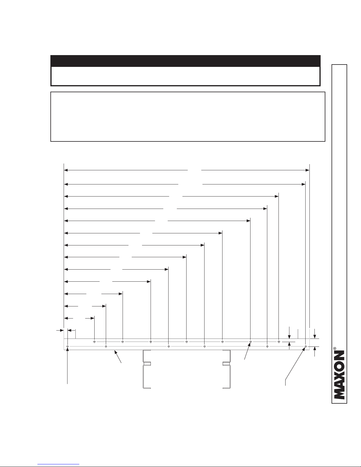
1. Mark and drill holes into rear sill as shown in FIG. 20-1.
96”
94-1/2”
82”
19”
14”
1-1/2”
24”
34”
41”
REAR
SILL
48”
55”
62”
72”
77”
USE 19/32” DRILL
(13 PLACES)
1-1/4”
11921 Slauson Ave. Santa Fe Springs, CA. 90670 (800) 227-4116 FAX (888) 771-7713
3-1/8”
HOLE ONLY REQUIRED
WHEN BOLTING
THROUGH CORNER POST.
REAR SILL - HOLE LOCATIONS FOR 96” WIDE VEHICLE
HOLE ONLY REQUIRED
WHEN BOLTING
THROUGH CORNER POST.
FIG. 20-1
20
STEP 1 - INSTALL EXTENSION PLATES - Continued
NOTE: Do not tighten extension plate bolts and lock nuts until:
• All the bolts and lock nuts are in place.
• Top of extension plate is ush with top of rear sill.
2. Bolt extension plate to vehicle as shown in FIG. 21-1. If necessary, reposition
extension plate so top surface is ush with top surface of sill. Then, torque bolts
and lock nuts to 105 lb.-ft.
FRAME BOLT, HEX
1/2”-13 X 1 3/4” LG, GR8
(13 PLACES)
VEHICLE
BODY
EXTENSION
PLATE
TEAR DROP NUT 1/2”-13
(13 PLACES 96” EXTENSION PLATE,
15 PLACES 102” EXTENSION PLATE)
3/16”
WELD VERT. EDGE
IF NOT BOLTING
BOLTING EXTENSION PLATE (96” WIDE EXTENSION PLATE SHOWN)
IF NO CORNER POST ACCESS FOR
BOLT & NUT, WELD OUTSIDE EDGES
AS SHOWN.
WELD VERT. EDGE
IF NOT BOLTING
FIG. 21-1
21
11921 Slauson Ave. Santa Fe Springs, CA. 90670 (800) 227-4116 FAX (888) 771-7713
3/16”
 Loading...