

Maxol HE28 Instructions Manual
SUPACOMBI HE28
G.C. Appliance No. 47-260-12
0086
Pin 87/BR/93
INSTALLATION & SERVICING INSTRUCTIONS
TO BE GIVEN TO THE USER

SECTION DESCRIPTION . . . . . . . . . . . . . . . . . . . . . . . . . . . PAGE NO
1INTRODUCTION . . . . . . . . . . . . . . . . . . . . . . . . . . . . . . . 0
1.1
Important Information . . . . . . . . . . . . . . . . . . . . . . . . . . . . . . . . . 1
1.2 General Description . . . . . . . . . . . . . . . . . . . . . . . . . . . . . . . . . . 1
2 TECHNICAL SPECIFICATIONS . . . . . . . . . . . . . . . . . . . . . . 2
2.1
Gas Categories . . . . . . . . . . . . . . . . . . . . . . . . . . . . . . . . . . . . . 2
2.2 Performance Data . . . . . . . . . . . . . . . . . . . . . . . . . . . . . . . . . . . 2
2.3 General Specifications . . . . . . . . . . . . . . . . . . . . . . . . . . . . . . . . 3
2.4 Overall Dimensions & Minimum Clearances . . . . . . . . . . . . . . . . . 4
2.5 Concentric Air / Flue Duct Specifications . . . . . . . . . . . . . . . . . . . 4
2.5.3 Additional Concentric Flue Kits Plume Diverter Kit . . . . . . . . . . . . . 5
2.5.4 Plume Diverter Kit . . . . . . . . . . . . . . . . . . . . . . . . . . . . . . . . . . . 6
2.6 Appliance Hydraulic Circuit . . . . . . . . . . . . . . . . . . . . . . . . . . . . 7
3 INSTALLATION REQUIREMENTS . . . . . . . . . . . . . . . . . . . . 8
3.1
Statutory Requirements . . . . . . . . . . . . . . . . . . . . . . . . . . . . . . . . 8
3.2 Appliance Location . . . . . . . . . . . . . . . . . . . . . . . . . . . . . . . . . . 8
3.3 Flue Terminal Position. . . . . . . . . . . . . . . . . . . . . . . . . . . . . . . . . 8
3.4 Ventilation Requirements. . . . . . . . . . . . . . . . . . . . . . . . . . . . . . . 8
3.5 Condensate Disposal . . . . . . . . . . . . . . . . . . . . . . . . . . . . . . . . . 9
3.6 Gas Supply. . . . . . . . . . . . . . . . . . . . . . . . . . . . . . . . . . . . . . . . 9
3.7 Central Heating systems . . . . . . . . . . . . . . . . . . . . . . . . . . . . . . . 9
3.8 Domestic Hot Water System . . . . . . . . . . . . . . . . . . . . . . . . . . . 10
3.9 Electricity Supply . . . . . . . . . . . . . . . . . . . . . . . . . . . . . . . . . . . 11
3.10 External Controls . . . . . . . . . . . . . . . . . . . . . . . . . . . . . . . . . . . 11
4 APPLIANCE INSTALLATION . . . . . . . . . . . . . . . . . . . . . . 12
4.1
Unpacking The Appliance. . . . . . . . . . . . . . . . . . . . . . . . . . . . . 12
4.2 Preparing The Wall . . . . . . . . . . . . . . . . . . . . . . . . . . . . . . . . . 12
4.3 Mounting The Appliance . . . . . . . . . . . . . . . . . . . . . . . . . . . . . 13
4.4 Central Heating and Domestic Hot Water Service Connections . . . 13
4.5 Gas Connection . . . . . . . . . . . . . . . . . . . . . . . . . . . . . . . . . . . 13
4.6 Condensate Connection . . . . . . . . . . . . . . . . . . . . . . . . . . . . . . 13
4.7 Pressure Relief Valve Connection . . . . . . . . . . . . . . . . . . . . . . . . 14
4.8 Air/Flue Duct Installation . . . . . . . . . . . . . . . . . . . . . . . . . . . . . 14
4.9 Electrical Connections . . . . . . . . . . . . . . . . . . . . . . . . . . . . . . . 15
5 COMMISSIONING AND TESTING. . . . . . . . . . . . . . . . . . 16
5.1
Filling the Water System. . . . . . . . . . . . . . . . . . . . . . . . . . . . . . 16
5.2 Commissioning the Appliance . . . . . . . . . . . . . . . . . . . . . . . . . . 17
5.3 DHW Flow Rate . . . . . . . . . . . . . . . . . . . . . . . . . . . . . . . . . . . 18
5.4 Final Checks . . . . . . . . . . . . . . . . . . . . . . . . . . . . . . . . . . . . . . 18
5.5 Lockout / Reset Indication. . . . . . . . . . . . . . . . . . . . . . . . . . . . . 18
5.6 Frost Protection . . . . . . . . . . . . . . . . . . . . . . . . . . . . . . . . . . . . 18
5.7 Overheat Protection . . . . . . . . . . . . . . . . . . . . . . . . . . . . . . . . . 18
5.8 Other Features. . . . . . . . . . . . . . . . . . . . . . . . . . . . . . . . . . . . . 18
5.9 Users Instructions . . . . . . . . . . . . . . . . . . . . . . . . . . . . . . . . . . . 19
5.10 Appliance Log Book. . . . . . . . . . . . . . . . . . . . . . . . . . . . . . . . . 19
6 ROUTINE SERVICING . . . . . . . . . . . . . . . . . . . . . . . . . . 20
6.1
Combustion Check. . . . . . . . . . . . . . . . . . . . . . . . . . . . . . . . . . 20
6.2 Removal of Casing Panels. . . . . . . . . . . . . . . . . . . . . . . . . . . . . 21
6.3 Burner Removal and Cleaning . . . . . . . . . . . . . . . . . . . . . . . . . . 21
6.4 Gas Rate Check . . . . . . . . . . . . . . . . . . . . . . . . . . . . . . . . . . . 22
6.5 Cleaning the Primary Heat Exchanger . . . . . . . . . . . . . . . . . . . . 22
6.6 Condensate Drain . . . . . . . . . . . . . . . . . . . . . . . . . . . . . . . . . . 22
6.7 Re-assembly . . . . . . . . . . . . . . . . . . . . . . . . . . . . . . . . . . . . . . 23
7 INTERNAL WIRING DIAGRAM . . . . . . . . . . . . . . . . . . . . 24
7.1
Functional Flow Wiring Diagram . . . . . . . . . . . . . . . . . . . . . . . . 24
8 FAULT FINDING . . . . . . . . . . . . . . . . . . . . . . . . . . . . . . 25
8.1
General . . . . . . . . . . . . . . . . . . . . . . . . . . . . . . . . . . . . . . . . . 25
8.2 Diagnostic Indicators . . . . . . . . . . . . . . . . . . . . . . . . . . . . . . . . 25
8.3 Fault Finding Codes . . . . . . . . . . . . . . . . . . . . . . . . . . . . . . . . . 25
8.4 DHW Fault Finding . . . . . . . . . . . . . . . . . . . . . . . . . . . . . . . . . 25
8.5 Central Heating Fault Finding . . . . . . . . . . . . . . . . . . . . . . . . . . 25
9 REPLACEMENT OF PARTS . . . . . . . . . . . . . . . . . . . . . . . 28
9.1
Primary Heat Exchanger. . . . . . . . . . . . . . . . . . . . . . . . . . . . . . 28
9.2 Combustion Chamber Insulation . . . . . . . . . . . . . . . . . . . . . . . . 28
9.3 Condensing Heat Exhanger . . . . . . . . . . . . . . . . . . . . . . . . . . . 28
9.4 Fan and Air Pressure Switch . . . . . . . . . . . . . . . . . . . . . . . . . . . 29
9.5 Burner . . . . . . . . . . . . . . . . . . . . . . . . . . . . . . . . . . . . . . . . . . 29
9.6 Ignition and Detection Electrodes. . . . . . . . . . . . . . . . . . . . . . . . 29
9.7 Gas Valve. . . . . . . . . . . . . . . . . . . . . . . . . . . . . . . . . . . . . . . . 29
9.8 Diverter Valve Actuator. . . . . . . . . . . . . . . . . . . . . . . . . . . . . . . 30
9.9 Draining the Boiler. . . . . . . . . . . . . . . . . . . . . . . . . . . . . . . . . . 30
9.10 CH Flow Switch. . . . . . . . . . . . . . . . . . . . . . . . . . . . . . . . . . . . 30
9.11 DHW Flow Sensor (Hall Effect) . . . . . . . . . . . . . . . . . . . . . . . . . 30
9.12 DHW Flow Regulator . . . . . . . . . . . . . . . . . . . . . . . . . . . . . . . . 31
9.13 DHW Plate Heat Exchanger . . . . . . . . . . . . . . . . . . . . . . . . . . . 31
9.14 CH/DHW Thermistors . . . . . . . . . . . . . . . . . . . . . . . . . . . . . . . 31
9.15 Pump . . . . . . . . . . . . . . . . . . . . . . . . . . . . . . . . . . . . . . . . . . . 31
9.16 Auto Air Vent . . . . . . . . . . . . . . . . . . . . . . . . . . . . . . . . . . . . . 32
9.17 Pressure Relief Valve. . . . . . . . . . . . . . . . . . . . . . . . . . . . . . . . . 32
9.18 Pressure Gauge . . . . . . . . . . . . . . . . . . . . . . . . . . . . . . . . . . . . 32
9.19 Condensate Trap . . . . . . . . . . . . . . . . . . . . . . . . . . . . . . . . . . . 32
9.20 Control PCB . . . . . . . . . . . . . . . . . . . . . . . . . . . . . . . . . . . . . . 33
9.21 Timeclock . . . . . . . . . . . . . . . . . . . . . . . . . . . . . . . . . . . . . . . . 33
10 SHORT PARTS LIST . . . . . . . . . . . . . . . . . . . . . . . . . . . . 34
The Maxol Supacombi HE 28 is a high efficiency
condensing, fully automatic, wall mounted, fan-assisted, balanced
flue gas combination appliance suitable for room sealed
applications, for use with natural gas (G20) only. This
combination appliance provides the user with both central heating
(CH) and domestic hot water (DHW) on demand.
The appliance features an attractive white stove enamelled
casing, with an inset control panel. The flue systems are in white
enamel to give a clean attractive appearance to the installation.
A telescopic horizontal concentric air/flue duct terminal is
available, (maximum duct length of 650 mm (25
1
⁄2 in)), suitable
for room sealed applications. The duct assembly is connected to
the appliance via a turret, which can be orientated to provide
different horizontal duct directions. Extension ducts may be fitted
in accordance with and up to the maximum dimensions stated in
these instructions.
A vertical concentric outlet kit is also available for installations
where an outside wall is not accessible or where it is desired to fit
the duct ‘through the roof’. Installation using the horizontal duct is
described in the main text of these instructions and additional
information is provided in the vertical outlet kit for the vertical
installation option. (Note: If the vertical outlet kit is to be used,
access to the roof is necessary).
Extension ducts are available, contact Technical Help Line:
01926 834834, for further details.
ONLY APPROVED FLUE KITS OR EXTENSIONS MAY BE
USED WITH THIS APPLIANCE.
CONTENTS INTRODUCTION
1

1
IT IS A STATUTORY REQUIREMENT THAT ALL GAS
APPLIANCES ARE INSTALLED BY COMPETENT PERSONS,
(i.e. CORGI REGISTERED INSTALLERS) IN ACCORDANCE
WITH THE GAS SAFETY (INSTALLATION AND USE)
REGULATIONS (CURRENT EDITION).
FAILURE TO COMPLY WITH THESE REGULATIONS MAY
LEAD TO PROSECUTION.
These appliances have been tested and certified in order to
satisfy the necessary European Directives and comply with the
latest Building Regulations, including the efficiency requirements
of the SEDBUK scheme.
Gas Appliance Directive 90/396/EEC
Efficiency of Hot Water Boilers Directive 92/42/EEC
Low Voltage Directive 93/68/EEC
Electromagnetic Compatibility Directive 92/31/EEC
No modifications to these appliances should be made unless they
are fully approved by the manufacturer.
Appliance installation must be carried out by a competent person
and must be in accordance with the current legislation in force at
the time of installation, in the country of destination.
The manufacturer's instructions must not be taken as overriding
any statutory requirements.
Control of Substances Hazardous to Health
Under Section 6 of the Health and Safety at Work Act 1974, it is
a requirement to provide information on substances hazardous to
health.
Maxol products are manufactured in accordance with ISO 9000
and do not, and will not, contain any hazardous materials or
substances such as asbestos, mercury or C.F.C.s.
The adhesives and sealants used in this appliance are cured and
give no known hazard in this state.
The appliance packaging does not contain any substances which
may be considered a hazard to health.
Combustion chamber panels
Material:
mineral fibres
Known hazards – If you have a history of skin complaint you may
be susceptible to irritation. High dust levels are usual only if the
material is broken. Some people can suffer reddening and itching
of the skin. Fibre entry in to the eye will cause foreign body
irritation, which can cause severe irritation to people wearing
contact lenses. Irritation to respiratory tract.
Precautions – Dust goggles will protect eyes. People with a history
of skin complaints may be particularly susceptible to irritation.
High dust levels are only likely to arise following harsh abrasion.
In general, normal handling and use will not present high risk,
follow good hygiene practices, wash hands before touching eyes,
eating, drinking or using the toilet.
First aid – If you do suffer irritation to the eyes or severe irritation
to the skin seek medical attention.
GAS LEAKS. DO NOT OPERATE ANY
ELECTRICAL SWITCHES, OR USE A NAKED
FLAME. TURN OFF THE GAS SUPPLY.
VENTILATE THE AREA BY OPENING DOORS AND
WINDOWS. CALL OUT YOUR LOCAL GAS SUPPLIER
TEL: 0800 111 999.
Gas and Electricity Consumer Council (Energywatch)
Energywatch is an independent organisation, which protects the
interests of gas users. If you need advice concerning energy
issues, they may be contacted on their consumer help line
number: 08459 060708, or via their web site;
http://www.energywatch.org.uk.
The appliance incorporates a microprocessor based safety
system, called DICOM (Digital Combustion) that consists of the
boilers main PCB, the gas control valve (CES) and the air
pressure switch for controlling and regulation of the modulating
atmospheric gas burner with fan. It has direct burner ignition,
which provides a modulated heat output to either central heating
(CH) or domestic hot water (DHW) demands, and with internal
frost protection provided as standard. The appliance incorporates
a domestic hot water (DHW) pre-heat feature which can
automatically adjust to the user’s habitual requirements. Thus
during long stand still periods, e.g. overnight, no pre-heat is
provided.
The appliance is designed for use with sealed primary water
systems and incorporates a circulating pump, diverter valve
assembly, pressure gauge, flow switch, safety valve and system
expansion vessel. A separate DHW expansion vessel is not
required. Isolation valves are fitted to the service connections and
an automatic heating by-pass is fitted to maintain an adequate
flow rate through the boiler.
The appliance has a DHW flow detection device, which gives
priority to DHW demand and proportions the required heating
load to the DHW flow rate, an electro-mechanical 24 hour time
clock is also fitted as standard.
The appliances may be used with any certified mains voltage
room thermostat, and can operate without the need for an
automatic bypass valve in the CH circuit. However, it is
recommended that one radiator in the room where the room
thermostat is fitted, is installed without thermostatic radiator valves
to allow the pump overrun facility to operate correctly. A separate
CH expansion vessel is not required if the total CH system content
is less than 84 litres, but one is required for systems with volumes
greater than 84 litres; refer to section 3.7. A separate DHW
expansion vessel is not required.
It is recommended that a drain cock is fitted at the lowest point in
the system.
1.1
IMPORTANT INFORMATION
1.2
GENERAL DESCRIPTION
!

2
Appliance Maxol
Supacombi HE 28
Mode Rate
Central Heating Output
Max
kW 28.3
(non-condensing)
(Btu/h) (96600)
(80 - 60 °C)
Min
kW 12.1
(Btu/h) (41300)
Central Heating Output (condensing)
Max
kW 30.7
(50 - 30 °C) (Btu/h) (104800)
Net
kW 29.0
Central Heating Input
(Btu/h) (99000)
Max Rate
Gross
kW 32.2
(Btu/h) (110000)
Net
kW 13.0
Central Heating Input
(Btu/h) (44400)
Min Rate
Gross
kW 14.4
(Btu/h) (49200)
Max
kW 28.3
Domestic Hot Water Output
(Btu/h) (96600)
Min
kW 12.1
(Btu/h) (41300)
Net
kW 29.0
Domestic Hot Water Input
(Btu/h) (99000)
Max Rate
Gross
kW 32.2
(Btu/h) (110000)
Net
kW 13.0
Domestic Hot Water Input
(Btu/h) (44400)
Min Rate
Gross
kW 14.4
(Btu/h) (49200)
Central Heating Gas Rate (after 10 min operation - hot)
m3/h 3.07
Max
ft3/h (108.4)
Domestic Hot Water Gas Rate (after 10 min operation - hot)
m3/h 3.07
Max
ft3/h (108.4)
Burner Pressure (at 20mbar inlet pressure)
Max 10.0
Min mbar 1.6
Ignition 6.0
Injectors 130
Seasonal Efficiency % 87.5
The appliance classification (as defined in EN 483) will be one of
the following depending on the chosen flue option: C
12, C32.
This appliance is certified to comply with the requirements of EN
483, EN 677, and EN 625 for use in GB and IE (Great Britain
and Ireland) using gas category 2H (G20 with a governed gas
supply at 20 mbar (8 in.wg) inlet pressure).
TECHNICAL SPECIFICATIONS
2
2.1
GAS CATEGORIES
2.2
PERFORMANCE DATA

Appliance Maxol
Supacombi HE 28
Seasonal Efficiency (SEDBUK) Band “B”
NOx Classification Class “2”
Design Domestic Hot Water Performance raised 35ºC
l/min 11.5
(gpm) (0.5)
DHW Specific Rate (D) EN625 l/min 13.5
Min Mains Water Inlet Pressure for Operation
Bar 0.3
(psi) (4.3)
Max Mains Water Inlet Pressure
Bar 10
(psi) (145)
Min Domestic Hot Water Flow Rate for Operation
l/min 2.5
(gpm) (0.5)
Min Central Heating System Pressure Bar 0.3
Max Central Heating System Pressure Bar 2.5
Max Domestic Hot Water Temperature °C 60
Min Domestic Hot Water Temperature °C 40
Max Central Heating Flow Temperature °C 80
Min Central Heating Flow Temperature °C 40
Appliance Maxol
Supacombi HE 28
Total weight (full) kg 54.0
Total weight (empty) kg 49.0
Max lift weight kg 43.0
Total water capacity Ltr 4.8
Integral expansion vessel capacity Ltr 8
Maximum heating system water content
using fitted expansion vessel, @ 0.75 bar
Ltr 84
Electrical supply 230V~50Hz Fuse at 3A
Internal fuse None
Maximum power consumption W 130
IP Rating IP20
CO2value max rate % 6.8 ± 1
CO value max rate ppm 75
Flue products mass flow rate g/s 17.0
Flue gas temperature - max rate °C 90
Connections
Gas 15 mm compression
CH flow 22 mm compression
CH return 22 mm compression
DHW inlet 15 mm compression
DHW outlet 15 mm Copper Tail
Pressure relief valve outlet 15 mm Copper Tail
Condensate Drain 19mm I/D Plastic overflow pipe
2.3
GENERAL SPECIFICATIONS
3
4
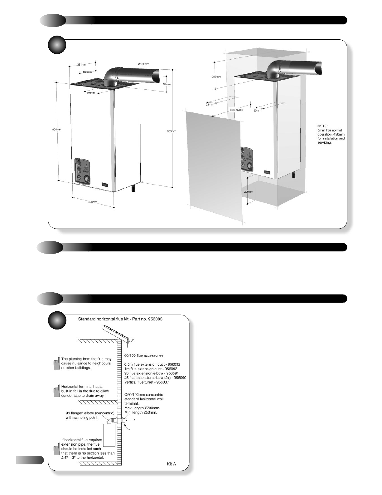
2.4
OVERALL DIMENSIONS AND MINIMUM CLEARANCES
The Maxol Supacombi HE 28 can be installed to a horizontal or
a vertical flue system. The different flue applications as shown in
Fig. 2a and Fig. 2b are available as a Horizontal Wall terminal
2.5
CONCENTRIC AIR / FLUE DUCT SPECIFICATIONS
2.5.1
UNIVERSAL TELESCOPIC WALL TERMINAL KIT (C12) - PART NO. 956120
kit or a Vertical Concentric flue terminal kit comprising the
connecting parts to the appliance and end terminal.
1
2a
(C12) – PART NO. 956120
Traditional concentric flue system, Fig. 2a, with a maximum length
of 2700mm. The flanged flue elbow is designed with 2.5° slope
towards the appliance so that the condensate can easily drain off.
When installing, please note that for every metre horizontal flue
length the terminal exit centreline is approx. 45 mm higher than
the elbow’s centreline.
The standard terminal is telescopic and can be used between
450 to 635 mm (from the centre of flue outlet to the outside wall,
but can be cut to a minimum flue length of 250mm, which is
suitable for single, 100mm (4"), brick walls.

5
TERMINAL KIT (C32)
- PART NO. 956081
2.5.2
VERTICAL CONCENTRIC FLUE
2b
Dimensions from vertical terminals to opening
windows should be in line with Fig. 4
The following additional concentric kits are available as optional
extras.
Flue Extension Ducts - 1000 mm and 500 mm long, (each
duct extends the flue length by up to 950 mm and 450 mm
respectively).
93° Extension Elbow - Allows an additional bend in the flue,
and has an 'equivalent length' of 1550 mm. This elbow is
mechanically different from the flanged elbow supplied as
standard with the kit, but has the same equivalent length.
45° Extension Elbow - Allows an additional bend in the flue
and has an 'equivalent length' of 775 mm.
The 'equivalent' flue length must not exceed the
maximum values stated.
These optional kits may be used with the standard flue kits to
produce an extended range of flue options, providing that the
following rules are strictly obeyed.
a) The maximum/minimum permissible length of the room sealed
flue system are:
2.5.3
ADDITIONAL CONCENTRIC FLUE KITS
b) The standard terminal must always be fitted horizontally;
horizontal ducts must have a continuous fall towards the
appliance of 2.5°. This ensures condensate runs back into the
appliance from the flue system. The vertical terminal must always
be used if a vertical outlet is required.
c) The concentric flue system must use either a flanged elbow or
a vertical flue turret socket at the entry/exit to the appliance.
d) All joints must be correctly made and secured in accordance
with the installation instructions. When cutting ducts, avoid swarf,
uneven and sharp edges to maintain duct integrity.
Standard concentric (ø100/60) vertical flue application with a
maximum length of 6400mm. The kit comprises of the roof
terminal, flashing kit, vertical adaptor with sampling point and
bracket.
The maximum length is measured from the top of the appliance
casing to the underside of the air cowl.
For installation details refer to the instructions
provided with the individual flue kits.
Horizontal flue terminal (all orientations) maximum 2700mm (106 in)
Horizontal flue terminal (rear exit) minimum 250 mm (10 in)
Vertical flue terminal maximum 6400 mm (252 in)
Vertical flue terminal minimum 600 mm (23
1
/2 in)
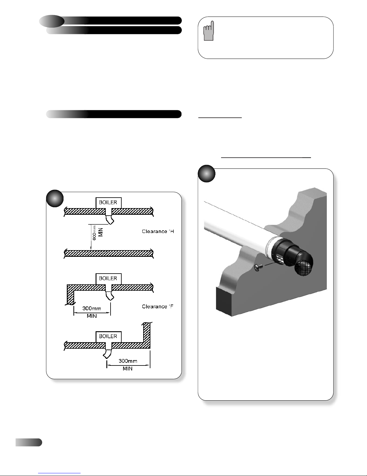
6
Under certain operating conditions condensing appliances have a
tendency to form a plume of water vapour at the terminal.
Therefore consideration should be given when fitting the Plume
Diverter in terms of plume dispersal onto adjacent surfaces and
neighbouring properties.
a) Refer to section 4.8 for instructions on fitting the flue system.
Also see Figure 4 for all other clearances.
INSTALLATION INSTRUCTIONS
The diverter allows the terminal clearance to be reduced as
follows (see diagram 2c):
Clearance H – From a surface facing the terminal - 600mm.
Clearance F – From internal or external clearances - 300mm.
b) Choose the direction required to deflect the flue products
(left or right only)
c) Push the diverter elbow onto the angled outlet of the flue
terminal in the desired rotational position and ensure the diverter
is pushed up to the shoulder to fully engage the rubber seal.
d) Fix the diverter to the flue terminal with the self drilling screw
provided.
Do not use a power tool to fit screw.
Note.
The Plume Diverter terminal must not under
any circumstances deflect flue products
downwards.
2c
2d
The resistance of the plume diverter is equivalent to
1.2 Mtrs of flue length. Ensure this is taken into account
when calculating the maximum allowable remaining flue
length. (ie Max flue length = 2.7 Mtrs subtract plume
diverter @ 1.2 Mtrs = 1.5 Mtrs remaining length)
Plume Diverter Kit Part No: 956103
(For use with Telescopic horizontal flue kit - Part no 956120 - only)
This kit is provided to assist in fitting a condensing boiler with
reduced clearances when fitted in good practice according to the
Guide to Condensing Boiler Installation published by
DEFRA/HMSO.
This kit allows the boiler flue outlet to be directed to the left or to
the right only.
INSTALLATION
PLUME DIVERTER TERMINAL
2.5.4
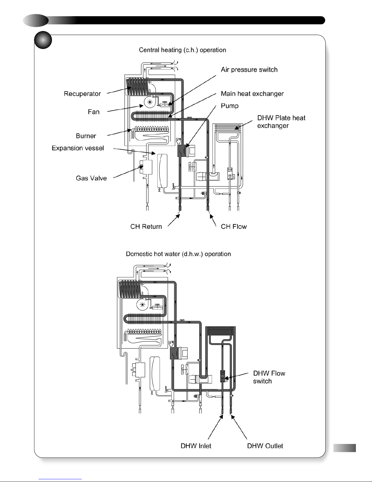
2.6
APPLIANCE HYDRAULIC CIRCUITS
3
7

8
INSTALLATION REQUIREMENTS
3
3.1
STATUTORY REQUIREMENTS
GAS SAFETY (INSTALLATION AND USE) REGULATIONS
The appliance is suitable only for installation in GB and IE and
should be installed in accordance with the rules in force.
In GB, a CORGI Registered Installer must carry out the installation.
It must be carried out in accordance with the current relevant
requirements of the:
Gas Safety (Installation and Use) Regulations
The appropriate Building Regulations either The Building
Regulations, The Building Regulations (Scotland), Building
Regulations (Northern Ireland).
The Water Fitting Regulations or Water Byelaws in Scotland.
The Current I.E.E Wiring Regulations.
Where no specific instructions are given, reference should be
made to the relevant British Standard code of Practice.
In IE, the installation must be carried out by a Competent Person
and installed in accordance with the current edition of I.S.813
"Domestic Gas Installations", the current Building Regulations and
reference should be made to the current ETCI rules for electrical
installation.
It should also be in accordance with the relevant recommendations
in the current editions of the following British Standards and Codes
of Practice: BS 5449, BS 5546, BS 5440-1, BS 5440-2, BS
6798, BS 6891, Institute of Gas Engineer document IGE/UP-7, BS
7074 (expansion vessel) and I.S.813 for IE.
IMPORTANT NOTE: Manufacturer’s instruction must NOT be
taken in any way as overriding statutory obligations.
3.3
FLUE TERMINAL POSITION
Detailed recommendations for flue installation are given
in BS 5440-1. The following notes are for general
guidance.
a) The appliance MUST be installed so that the terminal is exposed
to the external air.
b) It is important that the position of the terminal allows free
passage of air across it at all times.
c) It is ESSENTIAL TO ENSURE that products of combustion
discharging from the terminal cannot re-enter the building or any
other adjacent building, through ventilators, windows, doors, other
sources of natural air infiltration, or forced ventilation / air
conditioning.
d) The minimum acceptable dimensions from the terminal to
obstructions and ventilation openings are specified in Figure 4.
e) If the terminal discharges into a pathway or passageway check
that combustion products will not cause nuisance and that the
terminal will not obstruct the passageway.
f) Where the lowest part of the terminal is fitted less than 2000 mm
(78 in) above the ground, above a balcony or above a flat roof to
which people have access, the terminal MUST be protected by a
purpose designed K6 terminal guard (optional extra: Part No. 951507).
g) The air inlet / flue outlet MUST NOT be closer than 25 mm (1 in)
to combustible material.
h) Condensing appliances have a tendency to form a plume of
water vapour at the terminal under certain operating conditions. This
is normal but positions where this would cause damage or a
nuisance should be avoided. Consideration should be given to the
dispersal of the plume in terms of adjacent surfaces and
neighbouring properties.
3.2
APPLIANCE LOCATION
The following limitations MUST be observed when
siting the appliance:
a)
The appliance is not suitable for external installations. The
position selected for installation should be within the building,
unless otherwise protected by a suitable enclosure and MUST allow
adequate space for installation, servicing and operation of the
appliance and for air circulation around it (Section 2.4 and 3.4).
b) This position MUST allow for a suitable flue system and terminal
position. The appliance must be installed on a flat vertical wall,
which is capable of supporting the weight of the appliance and
any ancillary equipment.
c) If the appliance is to be fitted in a timber framed building it
should be fitted in accordance with the British Gas publication
‘Guide for Gas Installations In Timber Frame Housing’, Institute of
Gas Engineers document IGE/UP-7. If in doubt, advice must be
sought from the Local Gas Supplier.
d) The appliance is approved to a protection rating of IP20.
Therefore if the appliance is to be installed in a room containing a
bath or a shower, any electrical switch or control utilising mains
electricity must be so situated that it cannot be touched by a person
using the bath or shower. Attention is drawn to the requirements of
the current BS 7671 (I.E.E Wiring Regulations) and in Scotland the
electrical provisions of the Building Regulations applicable in
Scotland.
3.4
VENTILATION REQUIREMENTS
Detailed recommendations for air supply are given in BS 5440-2.
The following notes are for general guidance.
a) It is not necessary to have a purpose provided air vent in the
room or internal space in which a room-sealed appliance is
installed.
b) Cupboard or compartment ventilation is not necessary for a
room-sealed appliance providing that the minimum clearances are
maintained. Consideration must also be taken into account of the
clearance requirements for maintenance. On no account must
stored articles be allowed to come into contact with the boiler or
flue system.
c) If the appliance is installed in a room or internal space with
other opened flued appliance, then the size of the air vent
necessary should be calculated in accordance with BS 5440-2
Table 2.

9
It should be piped to drain, preferably within the building,
maintaining a continuous 2.5° (45 mm/m) fall away from the
appliance. If the drain is routed to outside it should be to a drain
or soak away, and any external pipe work should be in 32 mm.
Insulation to protection from freezing in cold weather conditions is
also advisable. Note if the appliance is installed in a garage all
pipe work should be in 32 mm. Ensure that the condensate
discharge system complies with any local regulations in force.
a) The Gas Supplier should be consulted at the installation planning
stage in order to establish the availability of an adequate supply of gas.
b) An existing service pipe MUST NOT be used without prior
consultation with the Gas Supplier.
c) A gas meter can only be connected by the Gas Supplier or by their
contractor.
d) An existing meter and/or pipe work should be of sufficient size to
carry the maximum appliance input plus the demand of any other
installed appliance. (BS 6891: 1988 or I.S.813 in Ireland).
A minimum of 22 mm diameter pipe work is
recommended within 1000 mm of the appliance gas cock.
e) Natural gas appliances:
The governor at the meter must give a
constant outlet pressure of 20 mbar (8 in.wg) when all appliances on
the system are running.
f) The gas supply line should be purged. WARNING: Before
purging open all doors and windows, also extinguish any cigarettes,
pipes, and any other naked lights.
g) The complete installation must be tested for gas tightness.
a) The appliance incorporates all the components necessary to allow it
to be connected to a sealed central heating system. Refer to Fig. 8 for
a typical system design, which incorporates radiators, and a drain
facility that must be provided at the lowest point in the system to allow
complete drain down.
4
FLUE TERMINAL POSITION
Position Minimum spacing
A Directly below an openable window, 300mm 12in
air vent, or any other ventilation opening
B Below gutter, drain/soil pipe 75mm 3in
C Below eaves 200mm 8in
D Below a balcony *600mm 98in
E From vertical drain pipes and soil pipes 150mm 6in
F From internal or external corners +300mm 12in
*1000mm 40in
G Above adjacent ground or balcony level 300mm 12in
H From a surface facing the terminal +600mm 24in
*2500mm 98in
I Facing terminals +1200mm 48in
*2500mm 98in
J From opening (door/window) in *not recommended
carport into dwelling
K Vertically from a terminal on the 1500mm 60in
same wall
L Horizontally from a terminal on the 300mm 12in
same wall
M Adjacent to opening 300mm 12in
N Below carport *not recommended
O From adjacent wall 600mm 12in
P From adjacent opening window 300mm 40in
Q From another terminal 600mm 24in
R Minimum height 300mm 12in
•
•
•
•
•
•
•
•
•
•
•
•
•
•
•
•
•
•
•
•
•
•
•
•
•
•
•
•
•
•
•
•
•
•
•
•
•
•
•
•
•
•
•
•
•
•
•
•
•
•
•
•
•
•
•
•
A
B,C
G
K
M
A
E
F
F
K
B,C
G
G
K
K
L
L
J
F
H,I
D,N
C
Q
O
O
P
R
SPECIAL REQUIREMENTS FOR A
VERTICALLY BALANCED FLUE
300mm
Min
430mm
Min
* Recommended by the boiler manufacturing industry to prevent
pluming nuisance and damage to buildings.
+ Distances, if plume diverter kit is fitted.
5
3.6
GAS SUPPLY
3.7
CENTRAL HEATING SYSTEM
3.5
CONDENSATE DISPOSAL
The boiler includes a condensate trap that prevents the
combustion products entering the drain; however an additional
trap is required, a seal of at least 75mm and an air break of at
least 75 mm between the traps (Fig. 5).
The condensate drain connection is suitable for 19mm I/D plastic
push fit or adhesive overflow pipes and fittings.
10
b) The installation should be designed to operate with a flow
temperature of up to 95°C.
c) A sealed system must only be filled by a competent person.
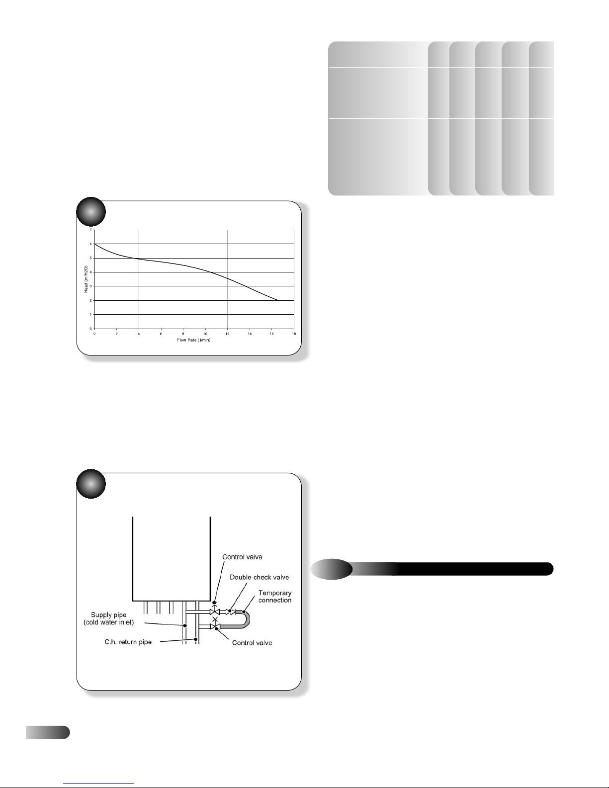
d) The available pump head for the appliance is given in Fig. 6.
e) If thermostatic radiator valves are fitted, a radiator must be
fitted with two lock shield valves, to enable correct operation of
the pump-overrun facility.
f) The following paragraphs outline the specifications of the
items fitted to the appliance.
PUMP – The available pump head shown in Fig. 6 is that in
excess of the appliance hydraulic resistance, i.e. that available
for the system.
EXPANSION VESSEL – The integral expansion vessel is pre-
charged to a pressure of between 0.5 and 1.0 bar. This should
be checked before the water system is filled. Details below show
the water system volume that is acceptable for this vessel. If the
system water volume is larger then an additional vessel must be
fitted to the system. BS 5449 and BS 6798 give further details
regarding expansion vessel sizing and sealed systems.
Expansion Vessel Requirements
Vessel charge and
bar 0.5 0.75 1.0 1.5
initial system pressure
Total water content of system
using 8 L (1.54 gal) capacity
L96847350
expansion vessel supplied
with appliance.
For systems having a larger
capacity multiply the total system
capacity in litres (gallons) by
0.0833 0.093 0.109 0.156
these factors to obtain the total
minimum expansion vessel
capacity required in litres.
PRESSURE GAUGE – A pressure gauge is situated on the
appliance control panel.
PRESSURE RELIEF VALVE – A pressure relief valve set to 3 bar
(43.5 psi) is supplied with the appliance; however it will start to
open at approximately 2.7 bar. It should not be used to flush the
system.
FILLING LOOP - This boiler is not fitted with a filling loop. Any
filling loop being fitted should comply with the water supply
(water fittings) regulations 1999 Section 24.
A filling loop should be fitted as shown in Fig. 7.
WATER TREATMENT, CLEANSING AND FLUSHING THE
HEATING SYSTEM
NOTE:
British Standard BS7593: 1992 stresses the importance of
cleansing and flushing of the system to ensure it continues to run
efficiently with the minimum of maintenance necessary. We fully
support this professional approach and recommend that the
system is cleansed with an effective chemical cleanser and
protected long term with a suitable inhibitor. Such products are
available from Fernox and Sentinel.
CONTROLS. As a minimum it is recommended that a room
thermostat be installed to control the appliance. Thermostatic
radiator valves may be fitted to the system; however they must not
be fitted in the room where the room thermostat is fitted. There
must be at least one radiator installed with lockshield valves that
should not be closed. Further guidance can be obtained from the
Domestic Heating and Hot Water Guide to the building
regulations.
7
6
7
7
3.8
DOMESTIC HOT WATER SYSTEM
a) Check that the mains water pressure is sufficient (as stated in 2.2
"Performance Data" – min 0.3 bar) to produce the required DHW
flow rate, but does not exceed the maximum DHW pressure (10 bar).
If necessary, a pressure-reducing valve must be fitted to the mains
supply before the DHW inlet connection.
b) The final 600 mm (24 in) of the mains supply pipe to the boiler
must be copper.
c) Avoid long DHW pipe runs and several hot water draw off points.
d) Insulate the hot water pipes if accessible to minimise the heat
losses within the pipes to keep the water hot longer.
 Loading...