

Maxnet MNDC, MNAC-110CM, MNAC-110, MNAC-220CM, MNRPS Operation Manual
...
D3.1 /
®
®
CCAP
Com
pliant
Pat. #s U.S. 6,842,348; 7,043,236;
Cdn. 2,404,840; 2,404,844
MNAC/MNDC Modular Power Supply
Installation & Operation Manual
™

Although every effort has been taken to ensure the accuracy of this document it may be necessary, without notice, to make amendments or correct omissions.
Specications subject to change without notice.
SignalOn® Series, MAXNET®, HFC Enhance®, PCI Filters®, Q-Series® & FiberLinx® are registered trademarks of ATX in the United States and/or other countries. SMACSM is a
service mark of ATX in the United States and/or other countries. Products or features contained herein may be covered by one or more U.S. or foreign patents. Other non-ATX
product and company names in this manual are the property of their respective companies.

TABLE OF CONTENTS
Page
1. PRODUCT DESCRIPTION ........................................................................................................................ 1-1
1.1. Technical Specications .................................................................................................................... 1-1
1.2. Functional Diagrams.......................................................................................................................... 1-2
2. INSTALLATION .........................................................................................................................................2-1
2.1. Product Inspection ............................................................................................................................. 2-1
2.2. Module Installation into the Active MAXNET® Chassis ...................................................................... 2-1
2.3. DC Redundant Powering of Active MAXNET® Chassis ..................................................................... 2-2
2.4. Module Power Requirements ............................................................................................................ 2-2
2.5. LED Indicator ..................................................................................................................................... 2-2
2.6. Voltage Monitor..................................................................................................................................2-2
3. MAINTENANCE & TROUBLESHOOTING ................................................................................................ 3-1
3.1. Maintenance ...................................................................................................................................... 3-1
3.2. Troubleshooting ................................................................................................................................. 3-1
4. SERVICE & SUPPORT ..............................................................................................................................4-1
4.1. Contact ATX Networks ....................................................................................................................... 4-1
4.2. Warranty Information ......................................................................................................................... 4-1
4.3. Safety ................................................................................................................................................ 4-1
i

Index of Figures & Tables
Figures
#1 MNDC Power Supply Functional Diagram ................................................................... 1-2
#2 MNAC-110 Power Supply Functional Diagram ............................................................. 1-2
#3 MNAC-220 Power Supply Functional Diagram ............................................................ 1-2
#4 MNAC-110CM Power Supply with Current Monitoring Functional Diagram ................. 1-2
#5 MNAC-220CM Power Supply with Current Monitoring Functional Diagram ................. 1-2
#6 MNRPS Remote Power Supply Functional Diagram .................................................... 1-2
#7 MNRPS(CM) Remote Power Supply with Current Monitoring Functional Diagram ..... 1-2
#8 MNAC Front & Rear Panel ........................................................................................... 2-2
#9 MNDC Front & Rear Panel ........................................................................................... 2-2
#10 MNRPS Front & Rear Panel ......................................................................................... 2-2
Tables
#1 Ordering Information ..................................................................................................... 1-1
#2 Technical Specications ...............................................................................................1-1
#3 Rear Terminal Block Assignment ..................................................................................2-1
#4 Module Power Requirements ....................................................................................... 2-2
ii
CHAPTER 1: PRODUCT DESCRIPTION
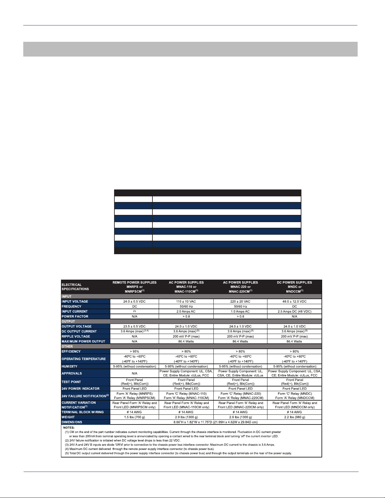
Part Number Description
MNDC -48 VDC to 24V, 3.6A True Load Sharing Redundant Power Supply
MNDCCM -48 VDC to 24V, 3.6A Power Supply with Current Monitor
PRODUCT DESCRIPTION
1. Product Description
The MNAC and MNDC are modular power supplies that supply the required +24 VDC to the MAXNET Active Chassis
backplane. This allows any MAXNET active module (AMP’s, RF Switch) to be installed in any remaining active chassis slot
to receive power. Both MNAC and MNDC have 24 VDC redundant powering capabilities, although only the MNDC provides
true load sharing. Installing two power supply modules into the chassis will maintain power to the backplane in the event that
one of them fails. Both the MNAC and the MNDC include a 24 VDC rear terminal block connection for the remote chassis
powering options. They are connected to the Active MAXNET Chassis through a hot-swapping backplane. The MNAC and
MNDC modules feature front panel LED power indication and +24 VDC backplane voltage monitor connections.
In addition to the standard powering modules, an optional current monitoring function is available in both the MNAC and
MNDC to provide remote indication (via the rear terminal block) of current uctuations caused by an active module failure.
The MNRPS is a module that supplies power to an Active MAXNET Chassis backplane from a remote 24 VDC source. It
features front panel LED power indication and +24 VDC backplane voltage monitor connections.
Please refer to the web page for up-to-date specications – atxnetworks.com
MNRPS 24V, 3.6A Remote Powering Unit
MNRPSCM 24V, 3.6A Remote Powering Unit with Current Monitoring
MNAC-110 110 VAC to 24V, 3.6A Diode or'd Redundant Power Supply
MNAC-110CM 110 VAC to 24V, 3.6A Power Supply with Current Monitor
MNAC-220 220 VAC to 24V, 3.6A Diode or'd Available (Consult ATX)
MNAC-220CM 220 VAC to 24V DC, 3.6A Power Supply with Current Monitor
Dimensions
1.1. TechnicalSpecications
8.66”H x 1.82”W x 11.75”D (21.99H x 4.62W x 29.84D cm)
Table #1: Ordering Information
Table#2:TechnicalSpecications
MAXNET® – MNAC/MNDC Modular Power Supply – Installation & Operation Manual 1-1
 Loading...